EP3755625B1 - Trennbare mehrteilige rahmenanordnung - Google Patents
Trennbare mehrteilige rahmenanordnung Download PDFInfo
- Publication number
- EP3755625B1 EP3755625B1 EP18738416.9A EP18738416A EP3755625B1 EP 3755625 B1 EP3755625 B1 EP 3755625B1 EP 18738416 A EP18738416 A EP 18738416A EP 3755625 B1 EP3755625 B1 EP 3755625B1
- Authority
- EP
- European Patent Office
- Prior art keywords
- spreader
- spreader portion
- aft
- lateral member
- coupler
- Prior art date
- Legal status (The legal status is an assumption and is not a legal conclusion. Google has not performed a legal analysis and makes no representation as to the accuracy of the status listed.)
- Active
Links
Images

Classifications
-
- B—PERFORMING OPERATIONS; TRANSPORTING
- B64—AIRCRAFT; AVIATION; COSMONAUTICS
- B64D—EQUIPMENT FOR FITTING IN OR TO AIRCRAFT; FLIGHT SUITS; PARACHUTES; ARRANGEMENT OR MOUNTING OF POWER PLANTS OR PROPULSION TRANSMISSIONS IN AIRCRAFT
- B64D11/00—Passenger or crew accommodation; Flight-deck installations not otherwise provided for
- B64D11/06—Arrangements of seats, or adaptations or details specially adapted for aircraft seats
- B64D11/0639—Arrangements of seats, or adaptations or details specially adapted for aircraft seats with features for adjustment or converting of seats
- B64D11/064—Adjustable inclination or position of seats
-
- B—PERFORMING OPERATIONS; TRANSPORTING
- B64—AIRCRAFT; AVIATION; COSMONAUTICS
- B64D—EQUIPMENT FOR FITTING IN OR TO AIRCRAFT; FLIGHT SUITS; PARACHUTES; ARRANGEMENT OR MOUNTING OF POWER PLANTS OR PROPULSION TRANSMISSIONS IN AIRCRAFT
- B64D11/00—Passenger or crew accommodation; Flight-deck installations not otherwise provided for
- B64D11/06—Arrangements of seats, or adaptations or details specially adapted for aircraft seats
- B64D11/0648—Lower frame constructions
-
- B—PERFORMING OPERATIONS; TRANSPORTING
- B64—AIRCRAFT; AVIATION; COSMONAUTICS
- B64D—EQUIPMENT FOR FITTING IN OR TO AIRCRAFT; FLIGHT SUITS; PARACHUTES; ARRANGEMENT OR MOUNTING OF POWER PLANTS OR PROPULSION TRANSMISSIONS IN AIRCRAFT
- B64D11/00—Passenger or crew accommodation; Flight-deck installations not otherwise provided for
- B64D11/06—Arrangements of seats, or adaptations or details specially adapted for aircraft seats
- B64D11/0693—Width modification of seat assemblies, e.g. for class modification
-
- B—PERFORMING OPERATIONS; TRANSPORTING
- B60—VEHICLES IN GENERAL
- B60R—VEHICLES, VEHICLE FITTINGS, OR VEHICLE PARTS, NOT OTHERWISE PROVIDED FOR
- B60R11/00—Arrangements for holding or mounting articles, not otherwise provided for
- B60R2011/0001—Arrangements for holding or mounting articles, not otherwise provided for characterised by position
- B60R2011/0003—Arrangements for holding or mounting articles, not otherwise provided for characterised by position inside the vehicle
- B60R2011/0012—Seats or parts thereof
- B60R2011/0014—Arm-rests
Definitions
- the field of the invention relates to separable multiple-piece frame assemblies for passenger seats in aircraft or the like.
- Passenger seats and particularly vehicle or aircraft passenger seats, are designed based on numerous factors including, for example, ensuring passenger safety for various loading conditions, minimizing weight, simplifying manufacturing, reducing cost, facilitating installation, simplifying shipping, among other factors.
- Conventional seats are typically designed for two to four occupants and use a framework arrangement with a frame assembly between adjacent seating positions along the lateral length of the seat and a plurality of support members that extend laterally and connect to each of the plurality of frame assemblies. Based on the cabin width of some vehicles (e.g., aircraft), in some cases, to optimize available space, it may be desirable to utilize a seat with five or more seating positions in the lateral direction of the seat.
- typical seats are designed with a maximum of four seating positions in the lateral direction because increasing the lateral dimension (beyond that of a four seating position seat) yields a seat that is impractical to ship, too large to manipulate into the vehicle, and is otherwise unworkable for varied reasons.
- Document US 5727845 describes an aircraft passenger seating unit providing seats for two or more passengers abreast which is convertible to provide different widths of seats by moving seat parts laterally with respect to one another between two configurations.
- the seats are defined by an end armrest at each side of the unit and by a pair of intermediate armrests between adjacent seats.
- a separable multiple-piece frame assembly according to claim 1 is provided.
- the plurality of attachments comprise at least one of fasteners and clamps.
- the forward coupler in certain embodiments, comprises: a hollow cylindrical member that is disposed within the forward lateral member; and a fastener for securing the forward coupler relative to the first spreader portion passes through a full diameter of the forward coupler and a full diameter of the forward lateral member.
- the first spreader portion comprises a seat pan portion and a seat back portion; and the second spreader portion comprises a seat pan portion and a seat back portion.
- the plurality of attachments comprise: at least two seat pan fasteners attaching the seat pan portion of the first spreader portion to the seat pan portion of the second spreader portion; and at least two seat back fasteners attaching the seat back portion of the first spreader portion to the seat back portion of the second spreader portion.
- the at least two seat pan fasteners comprise at least one of (i) a fastener located under an interface with a forward lateral member and (ii) a fastener located under an interface with an aft lateral member.
- a method according to claim 7 is provided.
- the method comprises: attaching a forward coupler to at least one of the first spreader portion and the second spreader portion such that, in an attached configuration, the forward coupler extends between (i) an interface of the first portion of the forward lateral member and the first spreader portion and (ii) an interface of the second portion of the forward lateral member and the second spreader portion; and attaching an aft coupler to at least one of the first spreader portion and the second spreader portion such that, in the attached configuration, the aft coupler extends between (i) an interface of the first portion of the aft lateral member and the first spreader portion and (ii) an interface of the second portion of the aft lateral member and the second spreader portion.
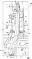
- Figs. 1-5 illustrate embodiments of separable multiple-piece frame assemblies 100 for passenger seats in vehicles such as an aircraft at a location where the seat would typically include a continuous portion that is not separable.
- the separable multiple-piece frame assembly 100 may include a first spreader portion 101 and a second spreader portion 201.
- Conventional seats include continuous lateral members that extend the full lateral length of the seat.
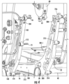
- a seat that incorporates the separable multiple-piece frame assembly 100 may include a forward lateral member separated into a first portion 31 and a second portion 32.
- the separable multiple-piece frame assembly 100 may also include an aft lateral member separated into a first portion 41 and a second portion 42.
- the lateral members 31, 32, 41, 42 attach to spreader members (including, for example, the separable multiple-piece frame assembly 100) and leg assemblies (not shown) that attach to a floor and/or substructure of the vehicle.
- forces due to passenger(s) in the seat result in loads that are transferred through the seat to at least one of the spreader members, before being transferred to at least one of lateral members, before eventually being transferred into at least one of the leg assemblies (and subsequently into the floor and/or substructure of the vehicle).
- Each of the spreader members includes (i) a seat pan portion that extends between a forward portion and an aft portion and (ii) a seat back portion that extends between the aft portion and an upper portion.
- the first spreader portion 101 includes (i) a seat pan portion that extends between a forward portion 102 and an aft portion 103 and (ii) a seat back portion that extends between the aft portion 103 and an upper portion 104.
- the second spreader portion 201 includes (i) a seat pan portion that extends between a forward portion 202 and an aft portion 203 and (ii) a seat back portion that extends between the aft portion 203 and an upper portion 204.
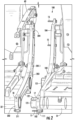
- the separable multiple-piece frame assembly 100 is shown in an attached configuration in Fig. 1 and in an detached configuration in Figs. 2-5 .
- first spreader portion 101 and the second spreader portion 201 are in face-to-face contact and are securely attached to one another.
- the inner face 101.1 of the first spreader portion 101 and the inner face 201.1 of the second spreader portion 201 are in contact with one another.
- the interface with the forward lateral member may include a cylindrical opening (in one or both of the first spreader portion 101 and the second spreader portion 201) with dimensions corresponding to the outer diameter of the forward lateral member.
- the interface with the aft lateral member may include a cylindrical opening (in one or both of the first spreader portion 101 and the second spreader portion 201) with dimensions corresponding to the outer diameter of the aft lateral member.
- At least one separable multiple-piece frame assembly 100 is located within a seat designed for five or more seating positions in the lateral direction. In some cases, the at least one separable multiple-piece frame assembly 100 separates the seat into multiple sections that each have four or fewer seating positions. For example, a separable multiple-piece frame assembly 100 can be used to separate an eight seating position seat into two sections that each have four seating positions. A separable multiple-piece frame assembly 100 can be used to separate a five seating position seat into two sections that have two and three seating positions.
- the separable multiple-piece frame assembly 100 may include a seat belt anchor that includes a first portion 51 attached to the aft portion 103 of the first spreader portion 101 and a second portion 52 attached to the aft portion 203 of the second spreader portion 201.
- the separable multiple-piece frame assembly 100 may also include an armrest assembly 60 that is attached to at least one of (i) the upper portion 104 of the first spreader portion 101 and (ii) the upper portion 204 of the second spreader portion 201.
- conventional seats are not separable at the location of the spreader member.
- conventional seats include a single spreader member, but the separable multiple-piece frame assembly 100 replaces a single spreader with the first spreader portion 101 and the second spreader portion 201 with a corresponding break in the lateral members (31/32 and 41/42), as described above.
- the single spreader member would be required to remain attached to one of the two sides leaving the second side unstable with nothing to support the cantilevered portions of the lateral members.
- the separable multiple-piece frame assembly 100 may include provisions for a plurality of attachments where the attachments may include at least one of fasteners, clamps, or any other appropriate mechanism for releasably attaching the first spreader portion 101 and the second spreader portion 201.
- the attachment(s) between the first spreader portion 101 and the second spreader portion 201 are configured such that the first spreader portion 101 and the second spreader portion 201 can be easily detached from one another for shipping, transport to a location for installation, or any other appropriate.
- the attachment(s) between the first spreader portion 101 and the second spreader portion 201 are configured such that the first spreader portion 101 and the second spreader portion 201 can be securely attached to one another to withstand appropriate loading conditions such that (once assembled at the separable multiple-piece frame assembly 100) the seat functions in the same manner as a conventional seat with a single spreader and continuous lateral members.
- the separable multiple-piece frame assembly 100 may include six fasteners for attaching the first spreader portion 101 and the second spreader portion 201.
- the separable multiple-piece frame assembly 100 may include any number of fasteners for attaching the first spreader portion 101 and the second spreader portion 201 (including fewer than or more than six fasteners).
- the separable multiple-piece frame assembly 100 may be configured to include two fasteners in the seat pan portion and two fasteners in the seat back portion (four total fasteners).
- a first fastener 11 attaches the front fastener portion 111 of the first spreader portion 101 and the front fastener portion 211 of the second spreader portion 201 ( see Figs.
- a second fastener 12 attaches the seat pan fastener portion 112 of the first spreader portion 101 and the seat pan fastener portion 212 of the second spreader portion 201 ( see Fig. 5 ).
- a third fastener 13 attaches the aft fastener portion 113 of the first spreader portion 101 and the aft fastener portion 213 of the second spreader portion 201 ( see Figs. 3 and 5 ).
- a fourth fastener 14 attaches the lower fastener portion 114 of the first spreader portion 101 and the lower fastener portion 214 of the second spreader portion 201 ( see Figs. 3 and 4 ).
- a fifth fastener 15 attaches the seat back fastener portion 115 of the first spreader portion 101 and the seat back fastener portion 215 of the second spreader portion 201 ( see Figs. 3 and 4 ).
- a sixth fastener 16 attaches the upper fastener portion 116 of the first spreader portion 101 and the upper fastener portion 216 of the second spreader portion 201 ( see Figs. 3 and 4 ).
- the fasteners 11-16 are illustrated such that the axial direction of each fastener is parallel to a lateral direction of the seat (e.g. , normal to a butt line plane of the vehicle, assuming the seat faces a fore/aft direction). However, the fasteners may be arranged in other orientations based on the appropriate attachments for the first spreader portion 101 and the second spreader portion 201.
- the front fastener portion 111 may be located in the forward portion 102 of the first spreader portion 101 ( see Figs. 1 , 2 , and 5 ). In some embodiments, the front fastener portion 111 is located directly underneath the interface between (i) the first spreader portion 101 and (ii) the first portion 31 of the forward lateral member. Similarly, the front fastener portion 211 may be located in the forward portion 202 of the second spreader portion 201. In some embodiments, the front fastener portion 211 is located directly underneath the interface between (i) the second spreader portion 201 and (ii) the second portion 32 of the forward lateral member.
- the seat pan fastener portion 112 may be located in the seat pan portion of the first spreader portion 101. In some embodiments, the seat pan fastener portion 112 is located approximately halfway between (i) the first portion 31 of the forward lateral member and (ii) the first portion 41 of the aft lateral member. Similarly, the seat pan fastener portion 212 may be located in the seat pan portion of the second spreader portion 201. In some embodiments, the seat pan fastener portion 212 is located approximately halfway between (i) the second portion 32 of the forward lateral member and (ii) the second portion 42 of the aft lateral member.
- the aft fastener portion 113 may be located in the aft portion 103 of the first spreader portion 101 ( see Figs. 3 and 5 ). In some embodiments, the aft fastener portion 113 is located directly underneath the interface between (i) the first spreader portion 101 and (ii) the first portion 41 of the aft lateral member. Similarly, the aft fastener portion 213 may be located in the aft portion 203 of the second spreader portion 201. In some embodiments, the aft fastener portion 213 is located directly underneath the interface between (i) the second spreader portion 201 and (ii) the second portion 42 of the aft lateral member.
- the lower fastener portion 114 may be located on an aft side of the aft portion 103 of the first spreader portion 101. In some embodiments, the lower fastener portion 114 is located directly aft of the interface between (i) the first spreader portion 101 and (ii) the first portion 41 of the aft lateral member. Similarly, the lower fastener portion 214 may be located on an aft side of the aft portion 203 of the second spreader portion 201. In some embodiments, the lower fastener portion 214 is located directly aft of the interface between (i) the second spreader portion 201 and (ii) the second portion 42 of the aft lateral member.
- the seat back fastener portion 115 may be located in the seat back portion of the first spreader portion 101 ( see Figs. 3 and 4 ). In some embodiments, the seat back fastener portion 115 is located approximately halfway between (i) the aft portion 103 of the first spreader portion 101 and (ii) the upper portion 104 of the first spreader portion 101. Similarly, the seat back fastener portion 215 may be located in the seat back portion of the second spreader portion 201. In some embodiments, the seat back fastener portion 215 is located approximately halfway between (i) the aft portion 203 of the second spreader portion 201 and (ii) the upper portion 204 of the second spreader portion 201.
- the upper fastener portion 116 may be located in the upper portion 104 of the first spreader portion 101. In some embodiments, the upper fastener portion 116 is located directly aft of the interface between (i) the first spreader portion 101 and (ii) the armrest assembly 60. Similarly, the upper fastener portion 216 may be located in the upper portion 204 of the second spreader portion 201. In some embodiments, the upper fastener portion 216 is located directly aft of the interface between (i) the second spreader portion 201 and (ii) the armrest assembly 60.
- the separable multiple-piece frame assembly 100 may include a forward coupler 121.
- the separable multiple-piece frame assembly 100 may also include a aft coupler 131 for attaching and aligning the first spreader portion 101, the second spreader portion 201, the first portion 41 of the aft lateral member, and the second portion 42 of the aft lateral member.
- the forward coupler 121 is shown attached to the first spreader portion 101, the forward coupler 121 may be attached to the second spreader portion 201. In some embodiments, as shown in Figs.
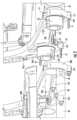
- the forward coupler 121 is a hollow cylindrical member attached to the first spreader portion 101 such that the forward coupler 121 is disposed within the first portion 31 of the forward lateral member and fastener 17 passes through the entire diameter of the forward coupler 121 and the entire diameter of the first portion 31 of the forward lateral member ( i.e ., the forward coupler 121 and the first portion 31 may each include holes corresponding to the fastener 17).
- the forward coupler 121 may include slots 122 such that the forward coupler 121 can be attached to the second spreader portion 201 such that the forward coupler 121 is inserted into the second portion 32 of the forward lateral member (without interfering with fastener 18). In the attached configuration (see Fig. 1 ), fastener 18 passes through the entire diameter of the forward coupler 121 and the entire diameter of the second portion 32 of the forward lateral member ( i.e ., the second portion 32 may include holes corresponding to the fastener 18).
- the couplers 121 and 131 in addition to facilitating attachment and alignment as described above, increase strength and the ability to transfer loads (e.g ., shear, bending, axial) through the separable multiple-piece frame assembly 100.
- the lateral members (which are continuous along the lateral length of conventional seats) play a significant role for transferring load due to the passenger of the seat through the structure of the seat and into the floor and/or substructure of the vehicle.
- the couplers 121 and 131 are designed with tight tolerances to engage the respective inner surfaces of the appropriate lateral members.
- the couplers 121, 131 are fixed to the lateral members with at least one fastener (e.g ., fasteners 17, 19).
- fasteners 17, 19 e.g ., fasteners 17, 19
- the couplers 121, 131 may be configured with fixed attachment to fasteners at each end thereof.
- the separable multiple-piece frame assembly 100 includes provisions (e.g ., portions 111-116, 211-216) for a plurality of fasteners (e.g.
- the couplers 121, 131 combine with the provisions for attaching the first spreader portion 101 and the second spreader portion 201 to maximize structural efficiency of the separable multiple-piece frame assembly 100.
- the aft coupler 131 is shown attached to the first spreader portion 101, the aft coupler 131 may be attached to the second spreader portion 201.
- the aft coupler 131 is a hollow cylindrical member attached to the first spreader portion 101 such that the aft coupler 131 is disposed within the first portion 41 of the aft lateral member and fastener 19 passes through the entire diameter of the aft coupler 131 and the entire diameter of the first portion 41 of the aft lateral member ( i.e ., the aft coupler 131 and the first portion 41 may each include holes corresponding to the fastener 19).
- the aft coupler 131 may include slots 132 such that the aft coupler 131 can be attached to the second spreader portion 201 such that the aft coupler 131 is inserted into the second portion 42 of the aft lateral member (without interfering with fastener 20).
- fastener 20 passes through the entire diameter of the aft coupler 131 and the entire diameter of the second portion 42 of the aft lateral member ( i.e ., the second portion 42 may include holes corresponding to the fastener 20).
- the armrest assembly 60 includes a fitting 61 that is sandwiched between upper portion 104 (of the first spreader portion 101) and upper portion 204 (of the second spreader portion 201).
- fastener 16 passes through upper portion 104, fitting 61, and upper portion 204.
- the fitting 61 may also include at least one fastener for attaching to at least one of the upper portion 104 and the upper portion 204.
- the upper portion 104 and/or the upper portion 204 may include a recessed area that approximately corresponds to the shape of fitting 61.
- the upper portion 104 and the upper portion 204 may include different recesses (e.g ., one may include a recess and one may include little or no recess).
- a method of assembling a seat that incorporates the separable multiple-piece frame assembly 100 may include attaching both the first spreader portion 101 and the second spreader portion 201 to the appropriate portions of the forward and aft lateral members.
- the first spreader portion 101 may be attached to (i) the first portion 31 of the forward lateral member using fastener 17 at forward portion 102 and to (ii) the first portion 41 of the aft lateral member using fastener 19 at aft portion 103.
- the second spreader portion 201 may be attached to (i) the second portion 32 of the forward lateral member using fastener 18 at forward portion 202 and to (ii) the second portion 42 of the aft lateral member using fastener 20 at aft portion 203.
- the assembly may include inserting forward coupler 121 into the first portion 31 of the forward lateral member before inserting fastener 17 through aligned holes in the forward portion 102, the forward coupler 121, and the first portion 31 of the forward lateral member.
- the assembly may also include inserting aft coupler 131 into the first portion 41 of the aft lateral member before inserting fastener 19 through aligned holes in the aft portion 103, the aft coupler 131, and the first portion 41 of the aft lateral member.
- the assembly before attaching the first spreader portion 101 and the second spreader portion 201 to one another, the assembly may include attaching the armrest assembly 60 to one of the first spreader portion 101 and the second spreader portion 201.
- Fig. 2 shows the armrest assembly 60 attached to the second spreader portion 201, but the armrest assembly 60 may be attached to the first spreader portion 101.
- the assembly of the seat may also include aligning the first spreader portion 101 and the second spreader portion 201 such that the forward coupler 121 is aligned with the corresponding hole of the forward portion 202 and the aft coupler 131 is aligned with the corresponding hole of the aft portion 203.
- the forward coupler 121 includes slots 122 that correspond to the fastener 18 and the aft coupler 131 includes slots 132 that correspond to the fastener 20.
- the assembly may include aligning slots 122 of the forward coupler 121 with fastener 18 of the second spreader portion 201 and aligning slots 132 of the aft coupler 131 with fastener 20 of the second spreader portion 201.
- the assembly may include attaching the first spreader portion 101 and the second spreader portion 201 such that the inner face 101.1 of the first spreader portion 101 and the inner face 201.1 of the second spreader portion 201 are in contact with one another such that a plurality of fasteners (e.g ., fasteners 11-16) attach the respective fastener portions (which described above).
- a plurality of fasteners e.g ., fasteners 11-16
- the components of the separable multiple-piece frame assembly 100 may be formed of materials including, but not limited to, aluminum, steel, titanium, carbon composite, graphite composite, polyester, nylon, plastic, thermoplastic, other fabric materials, stainless steel, other plastic or polymer materials, other metallic materials, other composite materials, or other similar materials. Moreover, the components of the separable multiple-piece frame assembly 100 may be attached to one another via suitable fasteners, which include, but are not limited to, screws, bolts, rivets or other mechanical or chemical fasteners.
Landscapes
- Engineering & Computer Science (AREA)
- Aviation & Aerospace Engineering (AREA)
- Seats For Vehicles (AREA)
- Chair Legs, Seat Parts, And Backrests (AREA)
Claims (8)
- Trennbare Verbundrahmenanordnung (100) für einen Passagiersitz eines Fahrzeugs, wobei die trennbare Verbundrahmenanordnung (100) umfasst:einen ersten Spreizerabschnitt (101) mit einer Innenfläche;einen zweiten Spreizerabschnitt (201) mit einer Innenfläche;eine Mehrzahl von Verbindungselementen (11 bis 16) zum lösbaren Verbinden des ersten Spreizerabschnitts (101) und des zweiten Spreizerabschnitts (201); und wobeidie trennbare Verbundrahmenanordnung (100) weiterhin umfasst:eine Verbindungskonfiguration, wobei die Innenfläche des ersten Spreizerabschnitts (101) und die Innenfläche des zweiten Spreizerabschnitts (201) miteinander in Kontakt stehen; undeine Armlehnenanordnung (60) mit einem Beschlag (61), der in der Verbindungskonfiguration zwischen dem ersten Spreizerabschnitt (101) und dem zweiten Spreizerabschnitt (201) eingeklemmt ist, wobeiein erster Abschnitt (31) eines Vorderseitenelements sich vom ersten Spreizerabschnitt (101) in eine entgegengesetzte Richtung zur Innenfläche (201.1) des ersten Spreizerabschnitts erstreckt; undein zweiter Abschnitt (32) des vorderen Seitenelements sich vom zweiten Spreizerabschnitt (201) in eine entgegengesetzte Richtung zur Innenfläche (101.1) des zweiten Spreizerabschnitts erstreckt,ein erster Abschnitt (41) eines Rückseitenelements sich vom ersten Spreizerabschnitt (101) in eine entgegengesetzte Richtung zur Innenfläche des ersten Spreizerabschnitts erstreckt; undein zweiter Abschnitt (42) des hinteren Seitenelements sich vom zweiten Spreizerabschnitt (201) in eine entgegengesetzte Richtung zur Innenfläche des zweiten Spreizerabschnitts erstreckt,eine vordere Kopplungsvorrichtung (121), wobei in der Verbindungskonfiguration sich die vordere Kopplungsvorrichtung (121) zwischen (i) einer Schnittstelle des ersten Abschnitts (31) des vorderen Seitenelements und dem ersten Spreizerabschnitt (101) und (ii) einer Schnittstelle des zweiten Abschnitts (32) des vorderen Seitenelements und des zweiten Spreizerabschnitts erstreckt; undeine hintere Kopplungsvorrichtung (131), wobei in der Verbindungskonfiguration sich die hintere Kopplungsvorrichtung (131) zwischen (i) einer Schnittstelle des ersten Abschnitts (41) des hinteren Seitenelements und dem ersten Spreizerabschnitt (101) und (ii) einer Schnittstelle zwischen dem zweiten Abschnitt (42) des hinteren Seitenelements und dem zweiten Spreizerabschnitt (201) erstreckt.
- Trennbare Verbundrahmenanordnung nach Anspruch 1, wobei die Mehrzahl von Verbindungselementen (11 bis 16) mindestens eines von Befestigungselementen und Klemmen umfassen.
- Trennbare Verbundrahmenanordnung nach Anspruch 1, wobei die vordere Kopplungsvorrichtung umfasst:ein hohles zylindrisches Element, das innerhalb des vorderen Seitenelements angeordnet ist; undein Befestigungselement zum Fixieren der vorderen Kopplungsvorrichtung relativ zum ersten Spreizerabschnitt (101), der sich durch den gesamten Durchmesser der vorderen Kopplungsvorrichtung und den gesamten Durchmesser des vorderen Seitenelements erstreckt.
- Trennbare Verbundrahmenanordnung nach einem der Ansprüche 1 bis 3, wobeider erste Spreizerabschnitt (101) einen Sitzplattenabschnitt und einen Sitzlehnenabschnitt umfasst; endder zweite Spreizerabschnitt (201) einen Sitzplattenabschnitt und einen Sitzlehnenabschnitt umfasst.
- Trennbare Verbundrahmenanordnung nach Anspruch 4, wobei die Mehrzahl von Verbindungselementen umfassen:mindestens zwei Sitzplattenbefestigungselementen, die den Sitzplattenabschnitt des ersten Spreizerabschnitts (101) mit dem Sitzplattenabschnitt des zweiten Spreizerabschnitts verbinden; Undmindestens zwei Rückenlehnenbefestigungselementen, die den Rückenlehnenabschnitt des ersten Spreizerabschnitts (101) mit dem Rückenlehnenabschnitt des zweiten Spreizerabschnitts (202) verbinden.
- Trennbare Verbundrahmenanordnung nach Anspruch 5, wobei die mindestens zwei Sitzplattentbefestigungselementen mindestens eine von (i) einem Befestigungselement unter einer Schnittstelle mit einem vorderen Seitenelement und (ii) einem Befestigungselement unter einer Schnittstelle mit einem hinteren Seitenelement umfassen.
- Verfahren zum Zusammenbau eines Passagiersitzes mit den folgenden Schritten:Bereitstellen einer trennbaren Verbundrahmenanordnung (100) nach einem der vorhergehenden Ansprüche, umfassend einen ersten Spreizerabschnitt (101) mit einer Innenfläche und einen zweiten Spreizerabschnitt (201) mit einer Innenfläche;Verbinden eines ersten Abschnitts (31) eines vorderen Seitenelements mit dem ersten Spreizerabschnitt;Verbinden eines zweiten Abschnitts (32) des vorderen Seitenelements mit dem zweiten Spreizerabschnitt;Verbinden eines ersten Abschnitts (41) eines hinteren Seitenelements mit dem ersten Spreizerabschnitt;Verbinden eines zweiten Abschnitts (42) des hinteren Seitenelements mit dem zweiten Spreizerabschnitt;Verbinden einer Armlehnenanordnung mit einem Beschlag indem der Beschlag zwischen dem ersten Spreizerabschnitt (101) und dem zweiten Spreizerabschnitt eingeklemmt wird; undVerbinden des ersten Spreizerabschnitts (101) und des zweiten Spreizerabschnitts (201) so, dass die Innenfläche des ersten Spreizerabschnitts (101) und die Innenfläche des zweiten Spreizerabschnitts (201) miteinander in Kontakt stehen und den Beschlag der Einzelarmlehne einklemmen.
- Verfahren nach Anspruch 7, weiterhin umfassend:Verbinden einer vorderen Kopplungsvorrichtung mit mindestens einem von dem ersten Spreizerabschnitt (101) und dem zweiten Spreizerabschnitt (201), so dass sich die vordere Kopplungsvorrichtung in einer Verbindungskonfiguration zwischen (i) einer Schnittstelle des ersten Abschnitts (31) des vorderen Seitenelements und des ersten Spreizerabschnitts (101) und (ii) einer Schnittstelle des zweiten Abschnitts (32) des vorderen Seitenelements und des zweiten Spreizerabschnitts erstreckt; undVerbinden einer hinteren Kopplungsvorrichtung mit einem von dem ersten Spreizerabschnitt (101) und dem zweiten Spreizerabschnitt (201), so dass sich die hintere Kopplungsvorrichtung in der Verbindungskonfiguration zwischen (i) einer Schnittstelle des ersten Abschnitts (41)) des hinteren Seitenelements und des ersten Spreizerabschnitts (101) und (ii) eine Schnittstelle des zweiten Abschnitts (42) des hinteren Seitenelements und des zweiten Spreizerabschnitts erstreckt.
Applications Claiming Priority (2)
| Application Number | Priority Date | Filing Date | Title |
|---|---|---|---|
| US201862633986P | 2018-02-22 | 2018-02-22 | |
| PCT/US2018/037726 WO2019164540A1 (en) | 2018-02-22 | 2018-06-15 | Separable multiple-piece frame assembly |
Publications (2)
| Publication Number | Publication Date |
|---|---|
| EP3755625A1 EP3755625A1 (de) | 2020-12-30 |
| EP3755625B1 true EP3755625B1 (de) | 2024-07-24 |
Family
ID=62846252
Family Applications (1)
| Application Number | Title | Priority Date | Filing Date |
|---|---|---|---|
| EP18738416.9A Active EP3755625B1 (de) | 2018-02-22 | 2018-06-15 | Trennbare mehrteilige rahmenanordnung |
Country Status (3)
| Country | Link |
|---|---|
| US (1) | US11383845B2 (de) |
| EP (1) | EP3755625B1 (de) |
| WO (1) | WO2019164540A1 (de) |
Families Citing this family (3)
| Publication number | Priority date | Publication date | Assignee | Title |
|---|---|---|---|---|
| WO2019074495A1 (en) * | 2017-10-11 | 2019-04-18 | Zodiac Seats Us Llc | CENTRAL ARMATURE ASSEMBLY IN TWO PARTS |
| US11623751B2 (en) * | 2021-09-03 | 2023-04-11 | Safran Seats Usa Llc | Spreader with open slot for passenger seat |
| US11505323B1 (en) * | 2021-09-03 | 2022-11-22 | Safran Seats Usa Llc | Connector for a tube assembly in a passenger seat |
Family Cites Families (13)
| Publication number | Priority date | Publication date | Assignee | Title |
|---|---|---|---|---|
| US5104065A (en) * | 1990-02-20 | 1992-04-14 | The Boeing Company | Readily convertible aircraft passenger seats |
| US5409186A (en) * | 1993-03-05 | 1995-04-25 | Eldec Corporation | Unitary seat support with integrated electronics |
| GB2280363B (en) * | 1993-07-29 | 1997-08-06 | Flight Equip & Eng | Armrest arrangements in convertible aircraft passenger seating |
| US6644738B2 (en) * | 2001-11-21 | 2003-11-11 | B E Aerospace, Inc. | Aircraft passenger seat frame construction |
| US20040099766A1 (en) * | 2002-11-27 | 2004-05-27 | Pratt John H. | Aircraft passenger seat with seat back control array |
| DE102009020199B4 (de) * | 2008-05-07 | 2022-06-09 | Zim Aircraft Seating Gmbh | Bausatz füt Sitzreihen in Flugzeugen |
| DE102008062113B4 (de) * | 2008-12-16 | 2020-01-23 | Zim Gmbh | Skelett für eine Fluggastsitzreihe |
| WO2014058399A1 (en) * | 2012-10-08 | 2014-04-17 | Assan Hani̇l Otomoti̇v Sanayi̇ Ve Ti̇caret Anoni̇m Şi̇rketi̇ | Modular spreaders and seatleg embodiment for chassis components of plane seats |
| EP2767470B1 (de) * | 2013-02-19 | 2019-09-18 | MIRUS Aircraft Seating Ltd. | Sitzteil für eine leichte Flugzeugpassagiersitzanordnung |
| EP3478580B1 (de) * | 2015-02-11 | 2021-10-20 | MIRUS Aircraft Seating Ltd. | Leichte flugzeugpassagiersitzanordnung |
| US10569881B2 (en) * | 2016-10-18 | 2020-02-25 | Molon Labe, Llc | Staggered aircraft seat assembly |
| DE102018006514A1 (de) * | 2018-08-17 | 2020-02-20 | Airbus Operations Gmbh | Sitzgruppenanordnung für eine Passagierkabine eines Flugzeuges |
| US10953777B1 (en) * | 2019-08-30 | 2021-03-23 | The Boeing Company | Extendable armrest assemblies for passenger vehicle seating |
-
2018
- 2018-06-15 WO PCT/US2018/037726 patent/WO2019164540A1/en not_active Ceased
- 2018-06-15 EP EP18738416.9A patent/EP3755625B1/de active Active
- 2018-06-15 US US16/970,940 patent/US11383845B2/en active Active
Also Published As
| Publication number | Publication date |
|---|---|
| US11383845B2 (en) | 2022-07-12 |
| US20200391869A1 (en) | 2020-12-17 |
| WO2019164540A1 (en) | 2019-08-29 |
| EP3755625A1 (de) | 2020-12-30 |
Similar Documents
| Publication | Publication Date | Title |
|---|---|---|
| US7338013B2 (en) | Floor for aircraft | |
| US8931847B2 (en) | Passenger seating assemblies and aspects thereof | |
| US7717519B2 (en) | Composite seat back structure for a lightweight aircraft seat assembly | |
| US8550564B1 (en) | Composite seat pan structure for a lightweight aircraft seat assembly | |
| US7191982B2 (en) | Floor for aircraft | |
| EP3694778B1 (de) | Zweiteilige mittelrahmenanordnung | |
| EP3755625B1 (de) | Trennbare mehrteilige rahmenanordnung | |
| US9126670B2 (en) | Panel assembly and method of making the same | |
| EP3152114B1 (de) | Faserverbund-hybrid strukturbauteil | |
| US20200247546A1 (en) | Seat assemblies, such as for use in aircraft, and associated systems and methods | |
| US12280698B2 (en) | Structural shroud assembly for passenger seat | |
| US20060049310A1 (en) | Overhead rest assembly | |
| EP3231703B1 (de) | Fachwerkstruktur | |
| JP7687856B2 (ja) | 荷重軽減のための滑り継ぎ手 | |
| US11117502B2 (en) | Variable section bench for seat | |
| EP4015385B1 (de) | Flugzeugpassagiersitzreihe mit flugbegleitersitz |
Legal Events
| Date | Code | Title | Description |
|---|---|---|---|
| STAA | Information on the status of an ep patent application or granted ep patent |
Free format text: STATUS: UNKNOWN |
|
| STAA | Information on the status of an ep patent application or granted ep patent |
Free format text: STATUS: THE INTERNATIONAL PUBLICATION HAS BEEN MADE |
|
| PUAI | Public reference made under article 153(3) epc to a published international application that has entered the european phase |
Free format text: ORIGINAL CODE: 0009012 |
|
| STAA | Information on the status of an ep patent application or granted ep patent |
Free format text: STATUS: REQUEST FOR EXAMINATION WAS MADE |
|
| 17P | Request for examination filed |
Effective date: 20200820 |
|
| AK | Designated contracting states |
Kind code of ref document: A1 Designated state(s): AL AT BE BG CH CY CZ DE DK EE ES FI FR GB GR HR HU IE IS IT LI LT LU LV MC MK MT NL NO PL PT RO RS SE SI SK SM TR |
|
| AX | Request for extension of the european patent |
Extension state: BA ME |
|
| DAV | Request for validation of the european patent (deleted) | ||
| DAX | Request for extension of the european patent (deleted) | ||
| STAA | Information on the status of an ep patent application or granted ep patent |
Free format text: STATUS: EXAMINATION IS IN PROGRESS |
|
| 17Q | First examination report despatched |
Effective date: 20220303 |
|
| GRAP | Despatch of communication of intention to grant a patent |
Free format text: ORIGINAL CODE: EPIDOSNIGR1 |
|
| STAA | Information on the status of an ep patent application or granted ep patent |
Free format text: STATUS: GRANT OF PATENT IS INTENDED |
|
| INTG | Intention to grant announced |
Effective date: 20240214 |
|
| GRAS | Grant fee paid |
Free format text: ORIGINAL CODE: EPIDOSNIGR3 |
|
| GRAA | (expected) grant |
Free format text: ORIGINAL CODE: 0009210 |
|
| STAA | Information on the status of an ep patent application or granted ep patent |
Free format text: STATUS: THE PATENT HAS BEEN GRANTED |
|
| AK | Designated contracting states |
Kind code of ref document: B1 Designated state(s): AL AT BE BG CH CY CZ DE DK EE ES FI FR GB GR HR HU IE IS IT LI LT LU LV MC MK MT NL NO PL PT RO RS SE SI SK SM TR |
|
| REG | Reference to a national code |
Ref country code: GB Ref legal event code: FG4D |
|
| REG | Reference to a national code |
Ref country code: CH Ref legal event code: EP |
|
| REG | Reference to a national code |
Ref country code: DE Ref legal event code: R096 Ref document number: 602018072171 Country of ref document: DE |
|
| REG | Reference to a national code |
Ref country code: IE Ref legal event code: FG4D |
|
| REG | Reference to a national code |
Ref country code: LT Ref legal event code: MG9D |
|
| REG | Reference to a national code |
Ref country code: NL Ref legal event code: MP Effective date: 20240724 |
|
| PG25 | Lapsed in a contracting state [announced via postgrant information from national office to epo] |
Ref country code: PT Free format text: LAPSE BECAUSE OF FAILURE TO SUBMIT A TRANSLATION OF THE DESCRIPTION OR TO PAY THE FEE WITHIN THE PRESCRIBED TIME-LIMIT Effective date: 20241125 |
|
| REG | Reference to a national code |
Ref country code: AT Ref legal event code: MK05 Ref document number: 1706092 Country of ref document: AT Kind code of ref document: T Effective date: 20240724 |
|
| PG25 | Lapsed in a contracting state [announced via postgrant information from national office to epo] |
Ref country code: NL Free format text: LAPSE BECAUSE OF FAILURE TO SUBMIT A TRANSLATION OF THE DESCRIPTION OR TO PAY THE FEE WITHIN THE PRESCRIBED TIME-LIMIT Effective date: 20240724 |
|
| PG25 | Lapsed in a contracting state [announced via postgrant information from national office to epo] |
Ref country code: PT Free format text: LAPSE BECAUSE OF FAILURE TO SUBMIT A TRANSLATION OF THE DESCRIPTION OR TO PAY THE FEE WITHIN THE PRESCRIBED TIME-LIMIT Effective date: 20241125 Ref country code: NL Free format text: LAPSE BECAUSE OF FAILURE TO SUBMIT A TRANSLATION OF THE DESCRIPTION OR TO PAY THE FEE WITHIN THE PRESCRIBED TIME-LIMIT Effective date: 20240724 |
|
| PG25 | Lapsed in a contracting state [announced via postgrant information from national office to epo] |
Ref country code: NO Free format text: LAPSE BECAUSE OF FAILURE TO SUBMIT A TRANSLATION OF THE DESCRIPTION OR TO PAY THE FEE WITHIN THE PRESCRIBED TIME-LIMIT Effective date: 20241024 |
|
| PG25 | Lapsed in a contracting state [announced via postgrant information from national office to epo] |
Ref country code: GR Free format text: LAPSE BECAUSE OF FAILURE TO SUBMIT A TRANSLATION OF THE DESCRIPTION OR TO PAY THE FEE WITHIN THE PRESCRIBED TIME-LIMIT Effective date: 20241025 Ref country code: FI Free format text: LAPSE BECAUSE OF FAILURE TO SUBMIT A TRANSLATION OF THE DESCRIPTION OR TO PAY THE FEE WITHIN THE PRESCRIBED TIME-LIMIT Effective date: 20240724 Ref country code: PL Free format text: LAPSE BECAUSE OF FAILURE TO SUBMIT A TRANSLATION OF THE DESCRIPTION OR TO PAY THE FEE WITHIN THE PRESCRIBED TIME-LIMIT Effective date: 20240724 |
|
| PG25 | Lapsed in a contracting state [announced via postgrant information from national office to epo] |
Ref country code: BG Free format text: LAPSE BECAUSE OF FAILURE TO SUBMIT A TRANSLATION OF THE DESCRIPTION OR TO PAY THE FEE WITHIN THE PRESCRIBED TIME-LIMIT Effective date: 20240724 |
|
| PG25 | Lapsed in a contracting state [announced via postgrant information from national office to epo] |
Ref country code: LV Free format text: LAPSE BECAUSE OF FAILURE TO SUBMIT A TRANSLATION OF THE DESCRIPTION OR TO PAY THE FEE WITHIN THE PRESCRIBED TIME-LIMIT Effective date: 20240724 |
|
| PG25 | Lapsed in a contracting state [announced via postgrant information from national office to epo] |
Ref country code: IS Free format text: LAPSE BECAUSE OF FAILURE TO SUBMIT A TRANSLATION OF THE DESCRIPTION OR TO PAY THE FEE WITHIN THE PRESCRIBED TIME-LIMIT Effective date: 20241124 Ref country code: AT Free format text: LAPSE BECAUSE OF FAILURE TO SUBMIT A TRANSLATION OF THE DESCRIPTION OR TO PAY THE FEE WITHIN THE PRESCRIBED TIME-LIMIT Effective date: 20240724 |
|
| PG25 | Lapsed in a contracting state [announced via postgrant information from national office to epo] |
Ref country code: HR Free format text: LAPSE BECAUSE OF FAILURE TO SUBMIT A TRANSLATION OF THE DESCRIPTION OR TO PAY THE FEE WITHIN THE PRESCRIBED TIME-LIMIT Effective date: 20240724 |
|
| PG25 | Lapsed in a contracting state [announced via postgrant information from national office to epo] |
Ref country code: RS Free format text: LAPSE BECAUSE OF FAILURE TO SUBMIT A TRANSLATION OF THE DESCRIPTION OR TO PAY THE FEE WITHIN THE PRESCRIBED TIME-LIMIT Effective date: 20241024 Ref country code: ES Free format text: LAPSE BECAUSE OF FAILURE TO SUBMIT A TRANSLATION OF THE DESCRIPTION OR TO PAY THE FEE WITHIN THE PRESCRIBED TIME-LIMIT Effective date: 20240724 |
|
| PG25 | Lapsed in a contracting state [announced via postgrant information from national office to epo] |
Ref country code: RS Free format text: LAPSE BECAUSE OF FAILURE TO SUBMIT A TRANSLATION OF THE DESCRIPTION OR TO PAY THE FEE WITHIN THE PRESCRIBED TIME-LIMIT Effective date: 20241024 Ref country code: PL Free format text: LAPSE BECAUSE OF FAILURE TO SUBMIT A TRANSLATION OF THE DESCRIPTION OR TO PAY THE FEE WITHIN THE PRESCRIBED TIME-LIMIT Effective date: 20240724 Ref country code: NO Free format text: LAPSE BECAUSE OF FAILURE TO SUBMIT A TRANSLATION OF THE DESCRIPTION OR TO PAY THE FEE WITHIN THE PRESCRIBED TIME-LIMIT Effective date: 20241024 Ref country code: LV Free format text: LAPSE BECAUSE OF FAILURE TO SUBMIT A TRANSLATION OF THE DESCRIPTION OR TO PAY THE FEE WITHIN THE PRESCRIBED TIME-LIMIT Effective date: 20240724 Ref country code: IS Free format text: LAPSE BECAUSE OF FAILURE TO SUBMIT A TRANSLATION OF THE DESCRIPTION OR TO PAY THE FEE WITHIN THE PRESCRIBED TIME-LIMIT Effective date: 20241124 Ref country code: HR Free format text: LAPSE BECAUSE OF FAILURE TO SUBMIT A TRANSLATION OF THE DESCRIPTION OR TO PAY THE FEE WITHIN THE PRESCRIBED TIME-LIMIT Effective date: 20240724 Ref country code: GR Free format text: LAPSE BECAUSE OF FAILURE TO SUBMIT A TRANSLATION OF THE DESCRIPTION OR TO PAY THE FEE WITHIN THE PRESCRIBED TIME-LIMIT Effective date: 20241025 Ref country code: FI Free format text: LAPSE BECAUSE OF FAILURE TO SUBMIT A TRANSLATION OF THE DESCRIPTION OR TO PAY THE FEE WITHIN THE PRESCRIBED TIME-LIMIT Effective date: 20240724 Ref country code: ES Free format text: LAPSE BECAUSE OF FAILURE TO SUBMIT A TRANSLATION OF THE DESCRIPTION OR TO PAY THE FEE WITHIN THE PRESCRIBED TIME-LIMIT Effective date: 20240724 Ref country code: BG Free format text: LAPSE BECAUSE OF FAILURE TO SUBMIT A TRANSLATION OF THE DESCRIPTION OR TO PAY THE FEE WITHIN THE PRESCRIBED TIME-LIMIT Effective date: 20240724 Ref country code: AT Free format text: LAPSE BECAUSE OF FAILURE TO SUBMIT A TRANSLATION OF THE DESCRIPTION OR TO PAY THE FEE WITHIN THE PRESCRIBED TIME-LIMIT Effective date: 20240724 |
|
| PG25 | Lapsed in a contracting state [announced via postgrant information from national office to epo] |
Ref country code: SM Free format text: LAPSE BECAUSE OF FAILURE TO SUBMIT A TRANSLATION OF THE DESCRIPTION OR TO PAY THE FEE WITHIN THE PRESCRIBED TIME-LIMIT Effective date: 20240724 Ref country code: RO Free format text: LAPSE BECAUSE OF FAILURE TO SUBMIT A TRANSLATION OF THE DESCRIPTION OR TO PAY THE FEE WITHIN THE PRESCRIBED TIME-LIMIT Effective date: 20240724 Ref country code: DK Free format text: LAPSE BECAUSE OF FAILURE TO SUBMIT A TRANSLATION OF THE DESCRIPTION OR TO PAY THE FEE WITHIN THE PRESCRIBED TIME-LIMIT Effective date: 20240724 |
|
| PG25 | Lapsed in a contracting state [announced via postgrant information from national office to epo] |
Ref country code: EE Free format text: LAPSE BECAUSE OF FAILURE TO SUBMIT A TRANSLATION OF THE DESCRIPTION OR TO PAY THE FEE WITHIN THE PRESCRIBED TIME-LIMIT Effective date: 20240724 |
|
| PG25 | Lapsed in a contracting state [announced via postgrant information from national office to epo] |
Ref country code: CZ Free format text: LAPSE BECAUSE OF FAILURE TO SUBMIT A TRANSLATION OF THE DESCRIPTION OR TO PAY THE FEE WITHIN THE PRESCRIBED TIME-LIMIT Effective date: 20240724 |
|
| REG | Reference to a national code |
Ref country code: DE Ref legal event code: R097 Ref document number: 602018072171 Country of ref document: DE |
|
| PG25 | Lapsed in a contracting state [announced via postgrant information from national office to epo] |
Ref country code: IT Free format text: LAPSE BECAUSE OF FAILURE TO SUBMIT A TRANSLATION OF THE DESCRIPTION OR TO PAY THE FEE WITHIN THE PRESCRIBED TIME-LIMIT Effective date: 20240724 Ref country code: SK Free format text: LAPSE BECAUSE OF FAILURE TO SUBMIT A TRANSLATION OF THE DESCRIPTION OR TO PAY THE FEE WITHIN THE PRESCRIBED TIME-LIMIT Effective date: 20240724 |
|
| PLBE | No opposition filed within time limit |
Free format text: ORIGINAL CODE: 0009261 |
|
| STAA | Information on the status of an ep patent application or granted ep patent |
Free format text: STATUS: NO OPPOSITION FILED WITHIN TIME LIMIT |
|
| 26N | No opposition filed |
Effective date: 20250425 |
|
| PGFP | Annual fee paid to national office [announced via postgrant information from national office to epo] |
Ref country code: DE Payment date: 20250618 Year of fee payment: 8 |
|
| PGFP | Annual fee paid to national office [announced via postgrant information from national office to epo] |
Ref country code: GB Payment date: 20250625 Year of fee payment: 8 |
|
| PGFP | Annual fee paid to national office [announced via postgrant information from national office to epo] |
Ref country code: FR Payment date: 20250623 Year of fee payment: 8 |
|
| PG25 | Lapsed in a contracting state [announced via postgrant information from national office to epo] |
Ref country code: SE Free format text: LAPSE BECAUSE OF FAILURE TO SUBMIT A TRANSLATION OF THE DESCRIPTION OR TO PAY THE FEE WITHIN THE PRESCRIBED TIME-LIMIT Effective date: 20240724 |
|
| REG | Reference to a national code |
Ref country code: CH Ref legal event code: H13 Free format text: ST27 STATUS EVENT CODE: U-0-0-H10-H13 (AS PROVIDED BY THE NATIONAL OFFICE) Effective date: 20260127 |
|
| PG25 | Lapsed in a contracting state [announced via postgrant information from national office to epo] |
Ref country code: MC Free format text: LAPSE BECAUSE OF FAILURE TO SUBMIT A TRANSLATION OF THE DESCRIPTION OR TO PAY THE FEE WITHIN THE PRESCRIBED TIME-LIMIT Effective date: 20240724 |
|
| PG25 | Lapsed in a contracting state [announced via postgrant information from national office to epo] |
Ref country code: LU Free format text: LAPSE BECAUSE OF NON-PAYMENT OF DUE FEES Effective date: 20250615 |
|
| REG | Reference to a national code |
Ref country code: BE Ref legal event code: MM Effective date: 20250630 |