EP4157656B1 - Elektrische mobile kühleinheit - Google Patents
Elektrische mobile kühleinheit Download PDFInfo
- Publication number
- EP4157656B1 EP4157656B1 EP21727346.5A EP21727346A EP4157656B1 EP 4157656 B1 EP4157656 B1 EP 4157656B1 EP 21727346 A EP21727346 A EP 21727346A EP 4157656 B1 EP4157656 B1 EP 4157656B1
- Authority
- EP
- European Patent Office
- Prior art keywords
- batteries
- battery
- power
- energy
- journey
- Prior art date
- Legal status (The legal status is an assumption and is not a legal conclusion. Google has not performed a legal analysis and makes no representation as to the accuracy of the status listed.)
- Active
Links
Images


Classifications
-
- B—PERFORMING OPERATIONS; TRANSPORTING
- B60—VEHICLES IN GENERAL
- B60R—VEHICLES, VEHICLE FITTINGS, OR VEHICLE PARTS, NOT OTHERWISE PROVIDED FOR
- B60R16/00—Electric or fluid circuits specially adapted for vehicles and not otherwise provided for; Arrangement of elements of electric or fluid circuits specially adapted for vehicles and not otherwise provided for
- B60R16/02—Electric or fluid circuits specially adapted for vehicles and not otherwise provided for; Arrangement of elements of electric or fluid circuits specially adapted for vehicles and not otherwise provided for electric constitutive elements
- B60R16/04—Arrangement of batteries
-
- F—MECHANICAL ENGINEERING; LIGHTING; HEATING; WEAPONS; BLASTING
- F25—REFRIGERATION OR COOLING; COMBINED HEATING AND REFRIGERATION SYSTEMS; HEAT PUMP SYSTEMS; MANUFACTURE OR STORAGE OF ICE; LIQUEFACTION SOLIDIFICATION OF GASES
- F25D—REFRIGERATORS; COLD ROOMS; ICE-BOXES; COOLING OR FREEZING APPARATUS NOT OTHERWISE PROVIDED FOR
- F25D11/00—Self-contained movable devices, e.g. domestic refrigerators
- F25D11/003—Transport containers
-
- B—PERFORMING OPERATIONS; TRANSPORTING
- B60—VEHICLES IN GENERAL
- B60H—ARRANGEMENTS OF HEATING, COOLING, VENTILATING OR OTHER AIR-TREATING DEVICES SPECIALLY ADAPTED FOR PASSENGER OR GOODS SPACES OF VEHICLES
- B60H1/00—Heating, cooling or ventilating devices
- B60H1/00007—Combined heating, ventilating, or cooling devices
- B60H1/00014—Combined heating, ventilating, or cooling devices for load cargos on load transporting vehicles
-
- B—PERFORMING OPERATIONS; TRANSPORTING
- B60—VEHICLES IN GENERAL
- B60H—ARRANGEMENTS OF HEATING, COOLING, VENTILATING OR OTHER AIR-TREATING DEVICES SPECIALLY ADAPTED FOR PASSENGER OR GOODS SPACES OF VEHICLES
- B60H1/00—Heating, cooling or ventilating devices
- B60H1/00421—Driving arrangements for parts of a vehicle air-conditioning
- B60H1/00428—Driving arrangements for parts of a vehicle air-conditioning electric
-
- B—PERFORMING OPERATIONS; TRANSPORTING
- B60—VEHICLES IN GENERAL
- B60H—ARRANGEMENTS OF HEATING, COOLING, VENTILATING OR OTHER AIR-TREATING DEVICES SPECIALLY ADAPTED FOR PASSENGER OR GOODS SPACES OF VEHICLES
- B60H1/00—Heating, cooling or ventilating devices
- B60H1/00642—Control systems or circuits; Control members or indication devices for heating, cooling or ventilating devices
- B60H1/00735—Control systems or circuits characterised by their input, i.e. by the detection, measurement or calculation of particular conditions, e.g. signal treatment, dynamic models
- B60H1/00764—Control systems or circuits characterised by their input, i.e. by the detection, measurement or calculation of particular conditions, e.g. signal treatment, dynamic models the input being a vehicle driving condition, e.g. speed
- B60H1/00771—Control systems or circuits characterised by their input, i.e. by the detection, measurement or calculation of particular conditions, e.g. signal treatment, dynamic models the input being a vehicle driving condition, e.g. speed the input being a vehicle position or surrounding, e.g. GPS-based position or tunnel
-
- B—PERFORMING OPERATIONS; TRANSPORTING
- B60—VEHICLES IN GENERAL
- B60H—ARRANGEMENTS OF HEATING, COOLING, VENTILATING OR OTHER AIR-TREATING DEVICES SPECIALLY ADAPTED FOR PASSENGER OR GOODS SPACES OF VEHICLES
- B60H1/00—Heating, cooling or ventilating devices
- B60H1/32—Cooling devices
- B60H1/3204—Cooling devices using compression
- B60H1/3232—Cooling devices using compression particularly adapted for load transporting vehicles
-
- B—PERFORMING OPERATIONS; TRANSPORTING
- B60—VEHICLES IN GENERAL
- B60L—PROPULSION OF ELECTRICALLY-PROPELLED VEHICLES; SUPPLYING ELECTRIC POWER FOR AUXILIARY EQUIPMENT OF ELECTRICALLY-PROPELLED VEHICLES; ELECTRODYNAMIC BRAKE SYSTEMS FOR VEHICLES IN GENERAL; MAGNETIC SUSPENSION OR LEVITATION FOR VEHICLES; MONITORING OPERATING VARIABLES OF ELECTRICALLY-PROPELLED VEHICLES; ELECTRIC SAFETY DEVICES FOR ELECTRICALLY-PROPELLED VEHICLES
- B60L1/00—Supplying electric power to auxiliary equipment of vehicles
- B60L1/02—Supplying electric power to auxiliary equipment of vehicles to electric heating circuits
-
- B—PERFORMING OPERATIONS; TRANSPORTING
- B60—VEHICLES IN GENERAL
- B60L—PROPULSION OF ELECTRICALLY-PROPELLED VEHICLES; SUPPLYING ELECTRIC POWER FOR AUXILIARY EQUIPMENT OF ELECTRICALLY-PROPELLED VEHICLES; ELECTRODYNAMIC BRAKE SYSTEMS FOR VEHICLES IN GENERAL; MAGNETIC SUSPENSION OR LEVITATION FOR VEHICLES; MONITORING OPERATING VARIABLES OF ELECTRICALLY-PROPELLED VEHICLES; ELECTRIC SAFETY DEVICES FOR ELECTRICALLY-PROPELLED VEHICLES
- B60L53/00—Methods of charging batteries, specially adapted for electric vehicles; Charging stations or on-board charging equipment therefor; Exchange of energy storage elements in electric vehicles
- B60L53/80—Exchanging energy storage elements, e.g. removable batteries
-
- B—PERFORMING OPERATIONS; TRANSPORTING
- B60—VEHICLES IN GENERAL
- B60L—PROPULSION OF ELECTRICALLY-PROPELLED VEHICLES; SUPPLYING ELECTRIC POWER FOR AUXILIARY EQUIPMENT OF ELECTRICALLY-PROPELLED VEHICLES; ELECTRODYNAMIC BRAKE SYSTEMS FOR VEHICLES IN GENERAL; MAGNETIC SUSPENSION OR LEVITATION FOR VEHICLES; MONITORING OPERATING VARIABLES OF ELECTRICALLY-PROPELLED VEHICLES; ELECTRIC SAFETY DEVICES FOR ELECTRICALLY-PROPELLED VEHICLES
- B60L58/00—Methods or circuit arrangements for monitoring or controlling batteries or fuel cells, specially adapted for electric vehicles
- B60L58/10—Methods or circuit arrangements for monitoring or controlling batteries or fuel cells, specially adapted for electric vehicles for monitoring or controlling batteries
- B60L58/12—Methods or circuit arrangements for monitoring or controlling batteries or fuel cells, specially adapted for electric vehicles for monitoring or controlling batteries responding to state of charge [SoC]
- B60L58/13—Maintaining the SoC within a determined range
-
- B—PERFORMING OPERATIONS; TRANSPORTING
- B60—VEHICLES IN GENERAL
- B60L—PROPULSION OF ELECTRICALLY-PROPELLED VEHICLES; SUPPLYING ELECTRIC POWER FOR AUXILIARY EQUIPMENT OF ELECTRICALLY-PROPELLED VEHICLES; ELECTRODYNAMIC BRAKE SYSTEMS FOR VEHICLES IN GENERAL; MAGNETIC SUSPENSION OR LEVITATION FOR VEHICLES; MONITORING OPERATING VARIABLES OF ELECTRICALLY-PROPELLED VEHICLES; ELECTRIC SAFETY DEVICES FOR ELECTRICALLY-PROPELLED VEHICLES
- B60L58/00—Methods or circuit arrangements for monitoring or controlling batteries or fuel cells, specially adapted for electric vehicles
- B60L58/10—Methods or circuit arrangements for monitoring or controlling batteries or fuel cells, specially adapted for electric vehicles for monitoring or controlling batteries
- B60L58/18—Methods or circuit arrangements for monitoring or controlling batteries or fuel cells, specially adapted for electric vehicles for monitoring or controlling batteries of two or more battery modules
- B60L58/21—Methods or circuit arrangements for monitoring or controlling batteries or fuel cells, specially adapted for electric vehicles for monitoring or controlling batteries of two or more battery modules having the same nominal voltage
-
- B—PERFORMING OPERATIONS; TRANSPORTING
- B60—VEHICLES IN GENERAL
- B60L—PROPULSION OF ELECTRICALLY-PROPELLED VEHICLES; SUPPLYING ELECTRIC POWER FOR AUXILIARY EQUIPMENT OF ELECTRICALLY-PROPELLED VEHICLES; ELECTRODYNAMIC BRAKE SYSTEMS FOR VEHICLES IN GENERAL; MAGNETIC SUSPENSION OR LEVITATION FOR VEHICLES; MONITORING OPERATING VARIABLES OF ELECTRICALLY-PROPELLED VEHICLES; ELECTRIC SAFETY DEVICES FOR ELECTRICALLY-PROPELLED VEHICLES
- B60L58/00—Methods or circuit arrangements for monitoring or controlling batteries or fuel cells, specially adapted for electric vehicles
- B60L58/10—Methods or circuit arrangements for monitoring or controlling batteries or fuel cells, specially adapted for electric vehicles for monitoring or controlling batteries
- B60L58/18—Methods or circuit arrangements for monitoring or controlling batteries or fuel cells, specially adapted for electric vehicles for monitoring or controlling batteries of two or more battery modules
- B60L58/22—Balancing the charge of battery modules
-
- B—PERFORMING OPERATIONS; TRANSPORTING
- B60—VEHICLES IN GENERAL
- B60P—VEHICLES ADAPTED FOR LOAD TRANSPORTATION OR TO TRANSPORT, TO CARRY, OR TO COMPRISE SPECIAL LOADS OR OBJECTS
- B60P3/00—Vehicles adapted to transport, to carry or to comprise special loads or objects
- B60P3/20—Refrigerated goods vehicles
-
- F—MECHANICAL ENGINEERING; LIGHTING; HEATING; WEAPONS; BLASTING
- F25—REFRIGERATION OR COOLING; COMBINED HEATING AND REFRIGERATION SYSTEMS; HEAT PUMP SYSTEMS; MANUFACTURE OR STORAGE OF ICE; LIQUEFACTION SOLIDIFICATION OF GASES
- F25B—REFRIGERATION MACHINES, PLANTS OR SYSTEMS; COMBINED HEATING AND REFRIGERATION SYSTEMS; HEAT PUMP SYSTEMS
- F25B27/00—Machines, plants or systems, using particular sources of energy
-
- F—MECHANICAL ENGINEERING; LIGHTING; HEATING; WEAPONS; BLASTING
- F25—REFRIGERATION OR COOLING; COMBINED HEATING AND REFRIGERATION SYSTEMS; HEAT PUMP SYSTEMS; MANUFACTURE OR STORAGE OF ICE; LIQUEFACTION SOLIDIFICATION OF GASES
- F25D—REFRIGERATORS; COLD ROOMS; ICE-BOXES; COOLING OR FREEZING APPARATUS NOT OTHERWISE PROVIDED FOR
- F25D29/00—Arrangement or mounting of control or safety devices
- F25D29/003—Arrangement or mounting of control or safety devices for movable devices
-
- B—PERFORMING OPERATIONS; TRANSPORTING
- B60—VEHICLES IN GENERAL
- B60L—PROPULSION OF ELECTRICALLY-PROPELLED VEHICLES; SUPPLYING ELECTRIC POWER FOR AUXILIARY EQUIPMENT OF ELECTRICALLY-PROPELLED VEHICLES; ELECTRODYNAMIC BRAKE SYSTEMS FOR VEHICLES IN GENERAL; MAGNETIC SUSPENSION OR LEVITATION FOR VEHICLES; MONITORING OPERATING VARIABLES OF ELECTRICALLY-PROPELLED VEHICLES; ELECTRIC SAFETY DEVICES FOR ELECTRICALLY-PROPELLED VEHICLES
- B60L2200/00—Type of vehicles
- B60L2200/28—Trailers
-
- B—PERFORMING OPERATIONS; TRANSPORTING
- B60—VEHICLES IN GENERAL
- B60L—PROPULSION OF ELECTRICALLY-PROPELLED VEHICLES; SUPPLYING ELECTRIC POWER FOR AUXILIARY EQUIPMENT OF ELECTRICALLY-PROPELLED VEHICLES; ELECTRODYNAMIC BRAKE SYSTEMS FOR VEHICLES IN GENERAL; MAGNETIC SUSPENSION OR LEVITATION FOR VEHICLES; MONITORING OPERATING VARIABLES OF ELECTRICALLY-PROPELLED VEHICLES; ELECTRIC SAFETY DEVICES FOR ELECTRICALLY-PROPELLED VEHICLES
- B60L2200/00—Type of vehicles
- B60L2200/36—Vehicles designed to transport cargo, e.g. trucks
-
- B—PERFORMING OPERATIONS; TRANSPORTING
- B60—VEHICLES IN GENERAL
- B60L—PROPULSION OF ELECTRICALLY-PROPELLED VEHICLES; SUPPLYING ELECTRIC POWER FOR AUXILIARY EQUIPMENT OF ELECTRICALLY-PROPELLED VEHICLES; ELECTRODYNAMIC BRAKE SYSTEMS FOR VEHICLES IN GENERAL; MAGNETIC SUSPENSION OR LEVITATION FOR VEHICLES; MONITORING OPERATING VARIABLES OF ELECTRICALLY-PROPELLED VEHICLES; ELECTRIC SAFETY DEVICES FOR ELECTRICALLY-PROPELLED VEHICLES
- B60L2240/00—Control parameters of input or output; Target parameters
- B60L2240/10—Vehicle control parameters
- B60L2240/34—Cabin temperature
-
- B—PERFORMING OPERATIONS; TRANSPORTING
- B60—VEHICLES IN GENERAL
- B60L—PROPULSION OF ELECTRICALLY-PROPELLED VEHICLES; SUPPLYING ELECTRIC POWER FOR AUXILIARY EQUIPMENT OF ELECTRICALLY-PROPELLED VEHICLES; ELECTRODYNAMIC BRAKE SYSTEMS FOR VEHICLES IN GENERAL; MAGNETIC SUSPENSION OR LEVITATION FOR VEHICLES; MONITORING OPERATING VARIABLES OF ELECTRICALLY-PROPELLED VEHICLES; ELECTRIC SAFETY DEVICES FOR ELECTRICALLY-PROPELLED VEHICLES
- B60L2240/00—Control parameters of input or output; Target parameters
- B60L2240/10—Vehicle control parameters
- B60L2240/36—Temperature of vehicle components or parts
-
- B—PERFORMING OPERATIONS; TRANSPORTING
- B60—VEHICLES IN GENERAL
- B60L—PROPULSION OF ELECTRICALLY-PROPELLED VEHICLES; SUPPLYING ELECTRIC POWER FOR AUXILIARY EQUIPMENT OF ELECTRICALLY-PROPELLED VEHICLES; ELECTRODYNAMIC BRAKE SYSTEMS FOR VEHICLES IN GENERAL; MAGNETIC SUSPENSION OR LEVITATION FOR VEHICLES; MONITORING OPERATING VARIABLES OF ELECTRICALLY-PROPELLED VEHICLES; ELECTRIC SAFETY DEVICES FOR ELECTRICALLY-PROPELLED VEHICLES
- B60L2240/00—Control parameters of input or output; Target parameters
- B60L2240/60—Navigation input
- B60L2240/66—Ambient conditions
- B60L2240/662—Temperature
-
- B—PERFORMING OPERATIONS; TRANSPORTING
- B60—VEHICLES IN GENERAL
- B60L—PROPULSION OF ELECTRICALLY-PROPELLED VEHICLES; SUPPLYING ELECTRIC POWER FOR AUXILIARY EQUIPMENT OF ELECTRICALLY-PROPELLED VEHICLES; ELECTRODYNAMIC BRAKE SYSTEMS FOR VEHICLES IN GENERAL; MAGNETIC SUSPENSION OR LEVITATION FOR VEHICLES; MONITORING OPERATING VARIABLES OF ELECTRICALLY-PROPELLED VEHICLES; ELECTRIC SAFETY DEVICES FOR ELECTRICALLY-PROPELLED VEHICLES
- B60L2260/00—Operating Modes
- B60L2260/40—Control modes
- B60L2260/46—Control modes by self learning
-
- Y—GENERAL TAGGING OF NEW TECHNOLOGICAL DEVELOPMENTS; GENERAL TAGGING OF CROSS-SECTIONAL TECHNOLOGIES SPANNING OVER SEVERAL SECTIONS OF THE IPC; TECHNICAL SUBJECTS COVERED BY FORMER USPC CROSS-REFERENCE ART COLLECTIONS [XRACs] AND DIGESTS
- Y02—TECHNOLOGIES OR APPLICATIONS FOR MITIGATION OR ADAPTATION AGAINST CLIMATE CHANGE
- Y02T—CLIMATE CHANGE MITIGATION TECHNOLOGIES RELATED TO TRANSPORTATION
- Y02T10/00—Road transport of goods or passengers
- Y02T10/60—Other road transportation technologies with climate change mitigation effect
- Y02T10/70—Energy storage systems for electromobility, e.g. batteries
-
- Y—GENERAL TAGGING OF NEW TECHNOLOGICAL DEVELOPMENTS; GENERAL TAGGING OF CROSS-SECTIONAL TECHNOLOGIES SPANNING OVER SEVERAL SECTIONS OF THE IPC; TECHNICAL SUBJECTS COVERED BY FORMER USPC CROSS-REFERENCE ART COLLECTIONS [XRACs] AND DIGESTS
- Y02—TECHNOLOGIES OR APPLICATIONS FOR MITIGATION OR ADAPTATION AGAINST CLIMATE CHANGE
- Y02T—CLIMATE CHANGE MITIGATION TECHNOLOGIES RELATED TO TRANSPORTATION
- Y02T10/00—Road transport of goods or passengers
- Y02T10/60—Other road transportation technologies with climate change mitigation effect
- Y02T10/7072—Electromobility specific charging systems or methods for batteries, ultracapacitors, supercapacitors or double-layer capacitors
-
- Y—GENERAL TAGGING OF NEW TECHNOLOGICAL DEVELOPMENTS; GENERAL TAGGING OF CROSS-SECTIONAL TECHNOLOGIES SPANNING OVER SEVERAL SECTIONS OF THE IPC; TECHNICAL SUBJECTS COVERED BY FORMER USPC CROSS-REFERENCE ART COLLECTIONS [XRACs] AND DIGESTS
- Y02—TECHNOLOGIES OR APPLICATIONS FOR MITIGATION OR ADAPTATION AGAINST CLIMATE CHANGE
- Y02T—CLIMATE CHANGE MITIGATION TECHNOLOGIES RELATED TO TRANSPORTATION
- Y02T10/00—Road transport of goods or passengers
- Y02T10/60—Other road transportation technologies with climate change mitigation effect
- Y02T10/72—Electric energy management in electromobility
-
- Y—GENERAL TAGGING OF NEW TECHNOLOGICAL DEVELOPMENTS; GENERAL TAGGING OF CROSS-SECTIONAL TECHNOLOGIES SPANNING OVER SEVERAL SECTIONS OF THE IPC; TECHNICAL SUBJECTS COVERED BY FORMER USPC CROSS-REFERENCE ART COLLECTIONS [XRACs] AND DIGESTS
- Y02—TECHNOLOGIES OR APPLICATIONS FOR MITIGATION OR ADAPTATION AGAINST CLIMATE CHANGE
- Y02T—CLIMATE CHANGE MITIGATION TECHNOLOGIES RELATED TO TRANSPORTATION
- Y02T10/00—Road transport of goods or passengers
- Y02T10/80—Technologies aiming to reduce greenhouse gasses emissions common to all road transportation technologies
- Y02T10/88—Optimized components or subsystems, e.g. lighting, actively controlled glasses
-
- Y—GENERAL TAGGING OF NEW TECHNOLOGICAL DEVELOPMENTS; GENERAL TAGGING OF CROSS-SECTIONAL TECHNOLOGIES SPANNING OVER SEVERAL SECTIONS OF THE IPC; TECHNICAL SUBJECTS COVERED BY FORMER USPC CROSS-REFERENCE ART COLLECTIONS [XRACs] AND DIGESTS
- Y02—TECHNOLOGIES OR APPLICATIONS FOR MITIGATION OR ADAPTATION AGAINST CLIMATE CHANGE
- Y02T—CLIMATE CHANGE MITIGATION TECHNOLOGIES RELATED TO TRANSPORTATION
- Y02T90/00—Enabling technologies or technologies with a potential or indirect contribution to GHG emissions mitigation
- Y02T90/10—Technologies relating to charging of electric vehicles
- Y02T90/16—Information or communication technologies improving the operation of electric vehicles
Definitions
- the present invention relates to electric mobile refrigeration units, and related software, systems and methods for deploying and managing such units.
- the capacity chosen for the refrigeration unit is highly dependent on the size of the trailer and the commodity that will be hauled.
- the refrigeration unit's capacity can range from less than 5kW to more than 15kW.
- a TRU's capacity is generally sized 50% larger than required to allow rapid temperature pull-down when the trailer is first loaded. Without this additional pull-down capacity, trailers would have to be precooled.
- TRUs are diesel driven, particularly when used with trailers. These typically use a small diesel engine to mechanically drive a compressor and power fans required for air distribution within the trailer. The period that the unit can operate on a payload of fuel depends on a number of variables such as ambient conditions, trailer design, and load requirements. Such units are well established in the industry. Nonetheless, diesel-powered TRUs have a number of drawbacks including noise and exhaust emissions. This is a particular problem, as the engine must be designed to have the power capacity to meet the pull-down requirements, i.e. chilling the interior and the contents down to the desired set point temperature, which is more power than is typically required during normal operation on the road to maintain that temperature. It is difficult to optimise a single engine to suit all possible cooling requirements. Due to these drawbacks, these units are facing a number of operational restrictions, especially during deliveries in large cities. Regulations such as ULEZ mean fleet operators need a clean, efficient solution.
- direct-drive Another technology is called “direct-drive", where the diesel engine of the tractor unit is also used to power the compressor of the refrigeration unit.
- the tractor unit engine is typically cleaner and more efficient than the small separate diesel engines used in TRUs.
- a hydraulic motor or electric motor may be used to couple power from the tractor engine to the compressor.
- hybrid diesel-electric units and other alternative technologies that incorporate electric power.
- Many hybrid units supplement the primary diesel engine with additional electric motors that allow the diesel engine to be switched off when the unit is plugged into grid-based electricity (shore power). This is referred to as “standby” operation.
- the electric motor is typically sufficient to maintain the desired set point cooling temperature when in standby operation, but does not have sufficient capacity to pull down the temperature to the desired set point.
- the diesel engine and the electric motor are mechanically coupled to the compressor "in parallel” via a belt or clutch mechanism that can selectively engage either power source as required.
- the diesel engine is used to produce AC power via an alternator/generator which is connected "in series” with an AC motor which drives the compressor.
- the AC motor can be connected to the electricity grid for standby operation.
- the AC motor driving the compressor can be supplied by shore power as well as by AC power generated by the tractor diesel engine.
- Such units where there is no separate diesel engine and the compressor is driven only by electrical power, are sometimes called eTRUs (electric TRUs).
- eTRU electric TRUs
- nomenclature is not entirely consistent across the industry, and the term "eTRU" can also be used to refer to units where the compressor is only driven electrically, i.e. via an AC motor, via either shore power or via a diesel engine, but without any mechanical coupling of the diesel engine to the compressor, and/or where the units have sufficient power to meet pull down requirements when operating on either power source.
- EP2528759B1 describes a "series" hybrid TRU arrangement which additionally has solar/battery storage providing power to the compressor via an AC bus.
- the diesel engine provides the main source of AC power via an alternator/generator to power the AC motor driving the compressor.
- a power management system also provides AC power converted from solar panels or a storage battery via an inverter, which can supplement or supplant the diesel engine power.
- an AC bus is created with power from either the diesel engine or the power management system.
- a charger is also connected to the AC bus, such that the battery can be charged from power generated by the diesel engine.
- US9440525B1 describes a "parallel" hybrid TRU arrangement which additionally has solar/battery storage providing power via a DC bus.
- the diesel engine is mechanically coupled to the compressor in the usual way for parallel designs.
- the solar panels and battery also provide power to the DC bus.
- An inverter on the bus then converts this to AC power to power the AC motor to drive the compressor.
- the diesel engine also powers a generator which provides DC power to a DC bus for recharging the batteries.
- a model is generated for each refrigeration unit, as performance may vary according to characteristics of the trailer, e.g. size of trailer, refrigeration system performance, effectiveness of insulation, etc, as well as the input parameters specific to the journey.
- the modelling comprises tracking movement of all TRUs across the fleet so as to determine the current status of the units and predicting future status of the units including energy consumption by the refrigeration units, energy generation by the solar units and energy flows around the system.
- a logistics company delivers milk at 5 degrees C to a supermarket on a 4 hour round trip in Scotland. This might take 3 battery modules. At a later point, they may contract to deliver ice cream in Malaga over a 12 hour round trip. This would clearly take more energy to provide the necessary refrigeration. The company can thus purchase more storage as and when needed for the fleet.
- the batteries may be moved using a mechanism which can align with both the on-vehicle racking system and static charging station so this operation can be performed with ease by a single operative.
- the fixed battery or batteries in contrast may be mounted in a different part of the mobile refrigeration unit, for instance in the housing of the main unit itself, where they are less accessible to operators in normal use and may require dismantling the unit to access the batteries.
- a CANbus link by which they can coordinate activity with other devices, e.g. other battery packs, chargers, the system controller.
- the system controller can control when the battery packs are connected to the bus, e.g. for delivering power to power consuming devices, e.g. the compressor, and drawing power for recharging.
- the DC bus may be a high current busbar and part of a power distribution unit (PDU), for instance provided within the TRU main body, also containing switched/non-switched connections, and a CAN to I/O interface circuit to switch the other contactors in the DC PDU.
- PDU power distribution unit
- each battery management system is configured to sense the voltage level of its battery and communicate with the battery management systems of the other batteries to manage the connection of the battery to the DC bus via its contactor such that the batteries with dissimilar voltages are not connected to the DC bus at the same time.
- This for instance allows the system to control which batteries are connected to the bus, and hence to each other, simultaneously, and hence manage the differing voltages in the batteries arising through having different States of Charge, by selectively connecting only individual batteries or batteries with similar voltages to avoid some batteries with higher voltages feeding current into other batteries with lower voltages.
- This may comprise selectively switching between batteries in turn via their contactors so a single battery supplies power to the DC bus at any time.
- the controller may selectively switch in one or more additional batteries once the voltages of one or more batteries already connected to the DC bus have equalised with the additional batteries such that the additional batteries and already connected batteries are then connected in parallel.
- additional batteries As batteries discharge, their voltages drop and other batteries, which initially have a lower state of charge and thus lower voltage, can safely be connected to the DC bus in parallel with the existing batteries as the voltages equalise.
- the unit comprises at least one solar panel, and optionally plural solar panels, for mounting to the trailer or vehicle, the power management system being arranged to receive DC power from the solar panel(s) for powering the compressor and charging the batteries.
- the solar panel(s) may be arranged to charge at least one battery of the refrigeration unit.
- the roof of the trailer or vehicle may be covered with solar panel(s) providing energy to charge the on-vehicle batteries and run the refrigeration system or feed back to the tractor unit to reduce fuel consumption, or to provide energy to the electricity grid when parked at the depot.
- the solar panel(s) may be connected to the DC bus, e.g. via charge controllers, to distribute power to the batteries and/or compressor and/or grid connector.
- the preferred refrigeration unit is thus a so-called "prosumer", i.e. both a consumer (via the refrigeration system) and producer (via solar) of electrical power.
- the solar panel (or each panel) may be connected to the power management system via a Maximum Power Point Tracker charge controller preferably including a bock-boost converter arranged to convert DC power from the solar panel to an appropriate voltage for charging the batteries.
- a Maximum Power Point Tracker charge controller preferably including a bock-boost converter arranged to convert DC power from the solar panel to an appropriate voltage for charging the batteries.
- the unit may also have a connector for connecting to a local or national electricity grid, wherein electric power from the solar panel or battery may be selectively exported to the connected electricity grid and/or the battery may be selectively charged from the connected electricity grid - either a local grid (i.e. behind the meter at the operator's depot) or the wider national grid.
- the connector may receive single phase or 3 phase power from the grid and a single directional or bi-directional charger may be provided for each phase or a 3 phase charger may be provided for charging the batteries.
- the batteries may be charged at a static charging station in situ in the refrigeration unit connected to the grid or via a battery swapping station where the battery is swapped out of the refrigeration unit.
- the static charging station is constantly connected to the grid (AC) to charge the batteries or to release surplus energy to the grid for demand side response, grid balancing or other grid connectivity.
- AC grid
- Both the on-vehicle fixed battery and the series of swappable batteries are connected to the power management system to convert electricity supply to the refrigeration system from DC to AC.
- the unit may be arranged to export energy to and/or from the tractor unit.
- Energy charging/export to/from tractor unit may be as beneficial as grid export/charging.
- excess power on the electrical system may be exported to the tractor unit, e.g. where a hybrid unit, to reduce diesel emissions, unloading the alternator, etc.
- Supplementary power may be imported from the tractor unit from the alternator and/or via axle re-generation (from the tractor or trailer).
- the mobile refrigeration units are primarily described in relation to refrigeration units for vehicles and trailers to cool the payload, i.e. so-called "TRUs - Transport Refrigeration Units", but other embodiments may relate to other mobile cooling/refrigeration solutions, such as air-conditioning units for transportation, etc.
- Trailers may include semi-trailers for tractor units, "reefer” units, refrigerated shipping containers, etc.
- the preferred embodiments achieve adequate and adaptive range, cost-competitiveness in equipment cost, zero emissions, and quieter operation.
- the preferred embodiments have various advantages.
- one advantage relates to limited power grid supply when charging.
- a fleet of electrical TRUs may require more electrical power than the local power grid can supply.
- the power grid may be unable to meet the demand.
- the battery swapping scheme of the preferred embodiments solves this problem by allowing slow charging of batteries in the charging station followed by swapping into the refrigeration unit for rapid deployment.
- further batteries are charging in readiness.
- the overall system therefore typically comprises more batteries than may be expected to be in use in TRUs at any one time.
- a battery charger converts an AC power input to a DC power output.
- the cost is highly dependent of the power rating.
- On-board chargers are cheaper than stationary fast-chargers but provide less power. It is not economically viable to provide a high quantity of fast chargers for a fleet, so slow on-board chargers are needed, and they can cause long charge durations.
- the cost of the battery makes up a large proportion of the cost of an eTRU.
- the size is determined by the worst-case scenario (long journey, high ambient temperature, etc).
- the worst-case scenario occurs infrequently, and so battery overcapacity is carried on most journeys causing the battery to be large and expensive.
- the unit may be arranged to monitor its usage, and comprising communication means to stream the usage data to a remote software platform, the usage data comprising one or more of: start time of journey; duration of journey; temperature set point; weather during journey; number, times and/or duration of delivery drops; payload mass and/or type; location data; energy usage; and actual temperature profile.
- the data may be used to model the performance of the refrigeration unit, i.e. the energy needed to achieve the temperature profile, given the other input parameters, so that predictions of energy use for future journeys can be made by inputting the appropriate input variables for the future journey.
- the data can also give real time feedback to operators of the system or the driver of the vehicle, and/or directly make adjustments to the refrigeration cycle.
- Energy usage may be any one or more of production, consumption and/or storage of electrical energy in the unit, i.e. solar energy, battery energy flows, energy consumed by the refrigeration unit, etc.
- Weather conditions may include ambient temperature and/or expected solar. These can be correlated with the times of the journey to estimate the amount of solar energy that will be generated and amount of energy to maintain the set point temperature. Payload mass and/or type affects the amount of cooling required to reach the set point.
- the unit is arranged to receive control signals from a remote software platform for charging the batteries and/or exporting power from the batteries and/or the solar panel to the electricity grid when connected.
- This may be the main power grid network, or the local grid, e.g. to supply power from the solar panel(s) or batteries of one trailer to another connected to he same local grid.
- the unit may include an uninterruptable power supply battery, separate from the batteries powering the refrigeration unit, to power the system controller to control charging of the fixed and swappable batteries.
- an uninterruptable power supply battery separate from the batteries powering the refrigeration unit, to power the system controller to control charging of the fixed and swappable batteries.
- the purpose of this is that the operator can always communicate with the TRU remotely, and it can for instance always monitor the solar energy available and thereby collect as much energy as possible. Thus, where the trailer is idle for a period of time, the controller may still monitor and manage the process of charging the fixed and swappable batteries from available PV.
- the unit comprises plural compressors in parallel, the controller being arranged to cumulatively engage the compressors in pulling down the temperature of the interior to a set point such that the power required remains within the power capability of the power management system.
- the power management system is arranged to deliver AC power to the compressor and the unit further comprising a variable speed drive for driving the compressor, such that the frequency of the AC power is modulated to adjust the power draw and limit the power draw to below the power management systems safe limit.
- the power distribution unit 60 may also have contactors for selectively supplying current to the fans and other components.
- a Human Machine Interface comprising a display and input means, e.g. a touch screen 80, connected with the system controller 75, e.g. by WiFi, by which an operator can locally see the status of the TRU and provide input/control.
- a display and input means e.g. a touch screen 80
- WiFi Wireless Fidelity
- Possibly inputs are one or more of:
- the system controller 75 can also be controlled directly from the cloud by the software 120, so settings can also be adjusted remotely.
- the system controller 75, gateway 76, and HMI 80 may be powered by an uninterruptable power supply (UPS) 81 which is a battery, separate from the fixed and swappable batteries and typically smaller. This is useful, for instance, where the trailer is parked up without any load and with partially charged batteries, the sun starts shining, and the contactors to the fixed or swappable batteries must be closed to allow charging with solar power or export to the grid.
- the controller is therefore "always on” and can be controlled remotely from anywhere via the cloud platform to monitor the available solar energy and if sufficient, turn on battery charging or export of energy to the grid.
- the UPS battery typically has sufficient capacity to power the controller for 24 to 48 hours, and is recharged automatically when there is power on the DC bus.
- the system 5 uses telematics and instrumentation specific for monitoring, including but not limited to, the electrical system 45 and refrigeration system 29 performance. Air temperature inside the trailer is automatically streamed and recorded and used to warn the driver and the fleet operator if temperatures move outside the desired range. All data is stored in the cloud and is used to teach a machine learning algorithm to create a digital twin of each TRU/trailer. The digital twin is subsequently stored in the cloud and is used to provide future energy prediction for each TRU/trailer and across the fleet.
- the system 5 comprises a fleet of trailers 12 and TRUs 14, and optionally at least one centralised static charging location, which in this example is a battery swapping station 100, e.g. located at the depot.
- the system 5 preferably uses plural batteries per TRU, the number and initial charge of which are configured by the software 120, here an IoT software platform running in the cloud 78 in conjunction with a machine learning algorithm that produces and updates digital twins. This enables the batteries 20, 50 to be small compared with prior art schemes, as the storage capacity can be adapted per journey.
- the software 120 manages batteries for the fleet of trailers and controls and monitors charging of the batteries at the charging location 100.
- the battery swapping station is adapted to receive the removable batteries 22 when removed from the trailer for charging under the control/monitoring of the software.
- batteries 22 may be charged in situ under the control/monitoring of the software 120 by connecting the TRUs 14 to the local electricity system via their connectors 62.
- the removable batteries may be swapped directly between the trailers in the fleet rather than via a battery swapping station.
- the static charging station is constantly connected to the grid (AC) 150 to charge the batteries via a charger, or to release surplus energy to the grid for demand side response, grid balancing or other grid connectivity.
- This is preferably a bi-directional charger (converts AC to DC one way, and inverts DC to AC the other way) as energy flows both ways.
- Such converters are known as "V2G” and "grid-tie” in other applications.
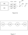
- FIG. 7 shows the main process carried out by the software.
- the software first predicts 710 the battery capacity for the journey.
- the software takes as input data representing a) the logistics schedule for the fleet, namely the desired temperature setting or profile for the goods being transported, the time and duration of the journey, the payload mass and/or type (i.e. a measure of how much is to be transported), and the number of delivery drops, b) the weather forecast and the hours of daylight of the journey, and c) the initial state of charge of the battery.
- the itinerary for the journey is obtained from the operator's logistics software, but could be manually entered by the operator; the weather information is obtained from an online source; and the battery charge information is determined from the swapping station and or system controller 75 of the TRU 10 depending on the current location of the battery.
- the software 120 looks at the TRUs available and selects the one which best matches the requirements for the journey.
- the software predicts the battery capacity, i.e. energy, required to complete the journey for the best match according to the input parameters, in particular the logistics schedule and weather forecast. It will be appreciated that weather conditions and expected hours of daylight during the journey will influence how much energy is generated via solar during the journey. Ambient air temperature will affect the cooling required. The number of stops for unloading affects loss of cooling, which requires additional energy from the system to compensate for.
- step 720 the software determines how many batteries are required for the journey and how much they need to be charged, taking into account the initial charge of the batteries and expected charging until the trailer must leave. Based on this, the closest match will then be charged according to the predicted energy requirement and/or the operator is instructed to swap, add or remove batteries to adapt the number of batteries if required and allow the operator to vary the on-vehicle battery capacity.
- the closest match needs another battery, the operator is instructed to add it. If the closest match has too many batteries on-board they may be removed as they can provide revenue via demand-side-response if they are left in the charging station at the depot. If there is time to charge 20kWh but only 10kWh is needed, the 10kWh may be sold to the national grid or used to charge another TRU in the fleet. Effectively, this means that the TRUs need not leave the depot with redundant battery capacity. Redundant battery capacity is better left at the depot to be used by another TRU or for demand-side-response.
- step 730 the batteries removed from a TRU 10 are moved to the charging station for offline charging or to another trailer.
- the software controls the charging of batteries in the battery swapping/charging station and/or in situ in connected TRUs.
- step 740 the trailer and TRU embarks with its adapted battery capacity.
- Figure 6a shows a fleet of trailers 12/TRUs 10 with various statuses being managed by the software platform 120.
- Figure 6a shows a TRU 10a with excess energy capacity being sold to the grid, a TRU 10b that requires additional batteries and charging via grid 150 and/or solar to reach the predicted energy capacity, a TRU 10c that will depart soon which has the required number of batteries and is disconnected from the swapping station and is undergoing final solar charging, a TRU 10d arriving back at the depot having finished a journey, and a TRU 10e departing the depot on a journey.
- Various batteries are shown in the battery swapping station 100 charging.
- FIG. 6b shows a method of energy prediction in more detail.
- a "digital twin" 610 is constructed to model each TRU 10 in the fleet.
- a digital twin is a digital representation that simulates virtually a real-life object, process or system.
- the digital twin comprises data in the form of physics-based mechanisms and models, relating to in particular the refrigerant cycle, heat loss from the trailer, etc; material properties and definitions of the system, such as characteristics of the trailer 12 and refrigeration system 29.
- the virtual representation of the twinned physical asset enables understanding of the behaviour of the physical object under various circumstances and in a variety of environmental conditions, so that its behaviour in the future can be predicted.
- each TRU 10 key usage metrics are continuously streamed from each TRU 10 to the cloud software 120.
- Data collected is linked to individual TRUs as each TRU will perform slightly differently from another. For instance, there may be different insulation thicknesses in different trailers, and/or damaged insulation on one trailer and not on another. There may be a TRU with a faulty/less efficient refrigeration cycle than another. A solar panel on one TRU may be damaged or dirty.
- the digital twin is created for each TRU in the fleet, or at least different types of TRU/trailers if those in the fleet can be sub-divided into categories.
- This streamed usage data creates historical data 620 of the performance of a TRU 10, i.e. the "response” of the system in terms of energy usage and temperature profile achieved, based on the "stimuli" to the system, i.e. the input data to the system as described above, i.e. the start time and duration of the trip, the desired temperature set-point, the prevailing weather conditions, the number, times, and durations of delivery drops, the payload capacity/utilisation, the location during the journey.
- This historical data is used to train the Digital Twin model via machine learning algorithms 640.
- the trained digital twin represents the digital behaviour blueprint of an individual TRU capturing the real-life response caused by indefinite combinations of stimuli at any given point in time.
- Figure 6c shows in more detail the digital twin models 610 being used to predict energy usage for a TRU 10 and across the fleet 10a..10n.
- the software 120 continuously monitors the present state 650 of the individual TRUs 10. This includes GPS location and battery state of charge.
- the present state provides a first input to the model 610.
- Future stimuli 655 are also input into the model 610, including the logistics schedule, i.e. when the TRUs must depart, number of deliveries, set-point temperature, time and duration of trip; and the weather forecast, i.e. to estimate ambient temperatures and solar energy available for the PV panels.
- the software can predict the energy required for a particular TRU to make the scheduled journey.
- the data that is used to create the digital twin 610 using machine learning 640 which is then used to make predictions 660 for a specific TRU/ journeyney and to manage the batteries across the fleet.
- the model predicts 660 (i) how long it takes to pull down, (ii) how much energy is needed to pull down, (iii) how much energy is needed for a specific journey, which is used to generate one or more actions 670 to adjust the battery capacity and/or charging required.
- "Pull down" usually takes place ahead of loading goods, either starting at the depot or on the way to the first pickup. So by predicting how long it takes to pull-down the software 120 can match when the trailer 12 needs to be ready for the goods. This minimises the time when the empty trailer is cooled to the required temperature ahead of the first pickup. The temperature may be preferentially pulled down whilst connected to the grid so less battery charging/capacity is needed.
- FIG. 4 shows typical temperature profile over time when operating a TRU 10.
- the TRU "pulls down" temperature inside the trailer 12 from ambient temperature 410 to a desired set point temperature 420 as required by the goods when being transported.
- the refrigerant is dense and so the pressure of the refrigerant is high.
- compressors 32 require a lot of power, especially during start-up, due to the high inrush currents.
- For a typical set point of 5 degrees C or -20 degrees C pull down from ambient temperature, say 20 degrees C, may take 30 minutes or more. Once the set point is reached, smaller energy output is required to keep the trailer at the desired temperature, depending again on ambient temperature and effectiveness of insulation of the trailer and resultant heat ingress.
- the amount of energy required over time for a particular journey is predicted using the energy prediction software 120 using the digital twin. It can be seen that the (in this example 10kWh) fixed battery 505 is sufficient for pulldown and maintaining the setpoint for an initial period of time 510.
- the adaptive battery capacity provided by the swappable batteries 515 is selected to provide sufficient energy to fulfil the total journey requirements, i.e. to move the line 515 along the axis such that the total battery capacity is adapted to the total journey time and requirements.
- the digital twin models 610 provide energy prediction 660 for the fleet. This comprises both what energy is available in the fleet (how much, where and when), and what energy is needed in the fleet (how much, where and when). Decisions are made by the software to balance the requirements, taking into account also the cost of electricity 680 and the potential profit from feeding energy back into the grid 150.
- various actions are taken by the energy prediction software 120 based on the balancing calculation.
- instructions can be issued to an operator to vary the number of swappable batteries 22 on the on-vehicle battery rack 20, based on expected consumption and hence the energy storage capacity.
- Unused batteries 22 are moved to the charging station 100 or other trailers 12 in the depot for offline charging under the control of the software so as to be ready for other upcoming journeys and/or participation in DSR services, i.e. the modification of consumer demand for energy and/or selling energy back to the national grid based on signals received from a utility company.
- the software controls charging and discharging of the connected batteries.
- the software platform 120 and charging station 100 has the capacity to manage a fleet of TRUs. This provides the ability for multiple TRUs to communicate with each other and share energy through battery swapping and vehicle to grid (V2G) technology.
- V2G Vehicle-to-grid
- plug-in electric vehicles such as battery electric vehicles (BEV), plug-in hybrids (PHEV) or hydrogen fuel cell electric vehicles (FCEV)
- BEV battery electric vehicles
- PHEV plug-in hybrids
- FCEV hydrogen fuel cell electric vehicles
- the power distribution unit 60 in each TRU and/or the power management system in the battery swapping station may be connected to the local AC grid, and thence to the grid 150, to charge the batteries or to provide V2G functionality, i.e. via an on-board or off-board bidirectional charger.
- a smart energy meter is mounted on the on-vehicle electrical circuit and the static charging station electrical circuit to monitor energy usage from the refrigeration system and supply energy usage information to a server.
- Plural TRUs may be connected together to become a "micro grid” and may be controlled through the software platform that uses energy prediction to instruct TRUs to either share energy (from solar or their batteries) with other TRUs (directly and/or via the battery swapping station), or charge their own battery depending on (i) photovoltaic power production (ii) grid electricity cost (iii) grid capacity, (v) demand from other TRUs or (vi) logistics schedule.
- variable speed drive 70 is used under the control of the system controller 75 to modify the frequency of the AC power supplied from the inverter part of the power management system from the battery system 22,50 and/or solar panel system 16 to the AC motor of the compressor 32 at start up so that the power applied by the motor gradually ramps up during start up, keeping the power requirement within the safe capabilities of the motor controller.
- the compressor is a reciprocating type.
- FIG. 8 there is an initial single compressor 32a and one or more additional compressors 32b,32c may be added in parallel to the initial compressor.
- the compressor is a scroll type.
- the controller 75 (not specifically shown in Figure 8 ) is arranged to turn on one compressor 32a, and once the suction pressure as measured by a sensor 44 has dropped sufficiently, the next compressor 32b can be engaged, once the suction pressure has dropped further, the next compressor 32c can be engaged, and so on.
- the electrical system 60 may be designed for a capacity of 10kW 518 with perhaps a maximum peak capacity of 12kW for short bursts.
- a first compressor is engaged at start up for approx. 10 minutes 520 requiring 5kW from the inverter consuming 0.8kWh, staying well within the inverter capacity.
- a second compressor 32b is engaged.
- the combined compressors operate for 10 minutes 540 requiring 7.5kW from the inverter consuming 1.3kWh, staying within the inverter capacity.
- a third compressor 32c is engaged.
- the combined compressors 32a,b,c operate for approx. 10 minutes 560 requiring approx. 10kW from the inverter consuming 1.7kWh, staying at or around the inverter capacity.
- compressors can be disengaged and a single compressor 32a is operated for periods of time to maintain the set point temperature.
- the system of plural compressors reduces inrush start-up current and provides capacity modulation.
Landscapes
- Engineering & Computer Science (AREA)
- Mechanical Engineering (AREA)
- Physics & Mathematics (AREA)
- Thermal Sciences (AREA)
- Power Engineering (AREA)
- Transportation (AREA)
- Life Sciences & Earth Sciences (AREA)
- Sustainable Development (AREA)
- Sustainable Energy (AREA)
- General Engineering & Computer Science (AREA)
- Remote Sensing (AREA)
- Radar, Positioning & Navigation (AREA)
- Chemical & Material Sciences (AREA)
- Combustion & Propulsion (AREA)
- Health & Medical Sciences (AREA)
- Public Health (AREA)
- Charge And Discharge Circuits For Batteries Or The Like (AREA)
Claims (15)
- Computerprogramm (120) zum Verwalten des Energiebedarfs mobiler Kühleinheiten (10), wobei die Kühleinheiten im Einsatz an einem Anhänger oder Fahrzeug (12) angebracht sind, um einen Innenraum davon während einer Fahrt zu kühlen, und durch eine oder mehrere wiederaufladbare Batterien (22) und optional ein oder mehrere Solarpaneele (16) mit Energie versorgt werden, wobei das Computerprogramm prozessorlesbare Anweisungen umfasst, die bewirken, wenn sie von dem Prozessor ausgeführt werden, dass der Computer:mindestens einen Fahrplan für eine bevorstehende Fahrt der Kühleinheit und eine Soll-Temperatur, die von der Kühleinheit zur Kühlung des Innenraums für diese Fahrt erreicht und aufrechterhalten werden soll, empfängt;den Energiebedarf zum Erreichen der Soll-Temperatur für die Fahrt modelliert und einen Batterieladezustand für die eine oder mehrere Batterien bestimmt, um diese Energie bereitzustellen, wobei das Computerprogramm dazu eingerichtet ist, historische Nutzungsdaten von Kühleinheiten während der Fahrten zu empfangen, wobei die Daten den einen oder die mehreren Parameter und Daten enthalten, die die von den Kühleinheiten erreichte Ist-Temperatur und den Energieverbrauch der Kühleinheiten angeben, wobei diese Daten verwendet werden, um digitale Zwillingsmodelle der Leistung der jeweiligen einzelnen Kühleinheiten über Algorithmen des maschinellen Lernens zu trainieren, und wobei das Modell für die bestimmte Kühleinheit, die die bevorstehende Fahrt unternimmt, bei der Bestimmung des Batterieladezustands verwendet wird; undentsprechend der Bestimmung ein Steuersignal an die Kühleinheit ausgibt, um zu bewirken, dass die erforderlichen Batterien auf den erforderlichen Stand aufgeladen werden.
- Computerprogramm nach Anspruch 1, wobei die Eingaben in das Modell, auf dessen Grundlage die Vorhersage des Energiebedarfs vorgenommen wird, einen oder mehrere der Parameter enthalten:gewünschter Temperatur-Sollwert;erwartete Wetterbedingungen während der Fahrt;Startzeit der Fahrt;Dauer der Fahrt;Anzahl, Zeiten und/oder Dauer der Auslieferungen;Nutzlastmasse und/oder -typ;und die Bestimmung die weitere Eingabe des Anfangsladezustands der Batterien berücksichtigt.
- Computerprogramm nach Anspruch 1, wobei das Computerprogramm mehrere digitale Zwillinge umfasst, die die erforderliche Energie und die verfügbare Energie über mehrere Kühleinheiten in einer Flotte von Anhängern oder Fahrzeugen hinweg modellieren, wobei das Computerprogramm dazu eingerichtet ist, Steuersignale auszugeben, um das Laden der Batterien über die gesamten Flotte hinweg zu optimieren.
- Computerprogramm nach Anspruch 3, wobei das Computerprogramm dazu eingerichtet ist, Steuersignale auszugeben, um den Export von überschüssiger elektrischer Energie von einer wiederaufladbaren Batterie oder einem Solarpaneel einer TRU in das nationale Stromnetz oder zu einer anderen wiederaufladbaren Batterie in einer anderen TRU, die am lokalen Stromnetz auflädt, zu bewirken.
- Computerprogramm nach Anspruch 4, wobei das Computerprogramm die Energie, die überschüssig ist, entsprechend den Kosten für Netzstrom bestimmt.
- Computerprogramm nach einem der Ansprüche 3 bis 5, wobei die Modellierung die Verfolgung der Bewegung aller TRUs über die gesamte Flotte hinweg umfasst, um den aktuellen Status der Einheiten zu bestimmen und den zukünftigen Status der Einheiten, einschließlich des Energieverbrauchs der Kühleinheiten, der Energieerzeugung durch die Solareinheiten und der Energieflüsse rund um das System vorherzusagen.
- Computerprogramm nach einem der Ansprüche 1 bis 6, wobei die Solarenergie bevorzugt gegenüber der Energie aus dem Stromnetz zum Aufladen der Batterien verwendet wird.
- Computerprogramm nach Anspruch 2, wobei das Computerprogramm über eine Schnittstelle mit einem Logistikprogramm, um die Fahrpläne für die Fahrten zu erhalten, und/oder mit einer Online-Quelle für Wetterinformationen verbunden ist.
- System (5) zum Aufladen von wiederaufladbaren Batterien (22) zur Energieversorgung von mobilen Kühleinheiten (10), wobei das System umfasst:Kühleinheiten, die eine oder mehrere wiederaufladbare Batterien zur Energieversorgung der Kühleinheiten umfasst, die im Einsatz an einem Anhänger oder Fahrzeug angebracht sind, um einen Innenraum davon während einer Fahrt zu kühlen;ein Computerprogramm (120) auf einem von den Kühleinheiten entfernt liegenden Server (89) nach einem der Ansprüche 1 bis 8;Mittel zum Kommunizieren zwischen dem entfernt liegenden Server und den Kühleinheiten.
- Kühleinheit (10) zum Kühlen des Innenraums eines Anhängers oder Fahrzeugs (12), wobei die Einheit umfasst:ein Kühlsystem (29) zur Montage an dem Anhänger oder Fahrzeug, mit einem Kompressor (32), einem Verdampfer (30), einem Kondensator (34), einem Expansionsventil (36) und einer Steuerung, das derart eingerichtet ist, dass die Aktivierung des Kompressors bewirkt, dass Kühlmittel zirkuliert und Wärme aus dem Innenraum über den Verdampfer abführt und Wärme über den Kondensator an die Umgebung abstrahlt;ein Batterie-Ablagegestell (20), in dem mehrere wiederaufladbare Batterien (22) so aufgenommen sind, dass sie in das Ablagegestell ein- und aus diesem heraus auswechselbar sind, damit die Batteriekapazität an eine bestimmte Fahrt angepasst werden kann; undein Energieverwaltungssystem (60), das dazu eingerichtet ist, Gleichstrom von den mehreren Batterien zu empfangen und Strom an den Kompressor zu liefern, wobei jede der mehreren wiederaufladbaren Batterien über einen Schütz (51) selektiv mit einem Gleichstrombus (52) des Energieverwaltungssystems elektrisch verbunden werden kann, um Strom zu liefern oder Strom zum Wiederaufladen der Batterie zu entnehmen, derart, dass Batterien mit unterschiedlichen Spannungen nicht parallel geschaltet werden;ein drahtloses Gateway (76), das dazu eingerichtet ist, Steuersignale von einer entfernten Softwareplattform zum Aufladen der Batterien gemäß einem Computerprogramm nach Anspruch 1 zu empfangen; undeine Steuerung (75), die dazu eingerichtet ist, das Kühlsystem zu steuern, um den Innenraum auf eine vorbestimmte Temperatur zu kühlen.
- Einheit nach Anspruch 10, wobei die austauschbare Batterie elektrisch mit einem Steckverbinder des Energieverwaltungssystems steckbar ist, wenn sie in dem Gestell aufgenommen ist.
- Einheit nach einem der Ansprüche 10 oder 11, umfassend mindestens ein Solarpaneel (16) zur Montage an dem Anhänger oder Fahrzeug, wobei das Energieverwaltungssystem dazu eingerichtet ist, Gleichstrom von dem Solarpaneel zu empfangen, um den Kompressor mit Energie zu versorgen und die Batterien aufzuladen.
- Einheit nach einem der Ansprüche 10 bis 12, wobei die Einheit einen Steckverbinder (62) zum Anschließen an ein lokales oder nationales Stromnetz aufweist, wobei elektrische Energie von dem Solarpaneel oder der Batterie selektiv in das angeschlossene Stromnetz exportiert werden kann und/oder die Batterie selektiv von dem angeschlossenen Stromnetz aufgeladen werden kann.
- Einheit nach einem der Ansprüche 10 bis 13, wobei die Einheit dazu eingerichtet ist, Energie zu und/oder von der Zugmaschine zu exportieren.
- Einheit nach einem der Ansprüche 10 bis 14, die dazu angeordnet ist, Nutzungsdaten der Einheit zu überwachen, und Kommunikationsmittel umfasst, um die Daten an eine entfernt liegende Softwareplattform zu streamen, wobei die Nutzungsdaten eines oder mehrere umfassen von:Startzeit der Fahrt;Dauer der Fahrt;Temperatursollwert;Wetter während der Fahrt;Anzahl, Zeiten und/oder Dauer von Auslieferungen;Nutzlastmasse und/oder -typ;Standortdaten;Energieverbrauch; undIst-Temperaturprofil.
Applications Claiming Priority (2)
| Application Number | Priority Date | Filing Date | Title |
|---|---|---|---|
| GBGB2008254.1A GB202008254D0 (en) | 2020-06-02 | 2020-06-02 | Electric mobile refrigeration unit |
| PCT/EP2021/062825 WO2021244832A1 (en) | 2020-06-02 | 2021-05-14 | Electric mobile refrigeration unit |
Publications (4)
| Publication Number | Publication Date |
|---|---|
| EP4157656A1 EP4157656A1 (de) | 2023-04-05 |
| EP4157656C0 EP4157656C0 (de) | 2025-04-02 |
| EP4157656B1 true EP4157656B1 (de) | 2025-04-02 |
| EP4157656B8 EP4157656B8 (de) | 2025-05-07 |
Family
ID=71526480
Family Applications (1)
| Application Number | Title | Priority Date | Filing Date |
|---|---|---|---|
| EP21727346.5A Active EP4157656B8 (de) | 2020-06-02 | 2021-05-14 | Elektrische mobile kühleinheit |
Country Status (4)
| Country | Link |
|---|---|
| US (1) | US20230174008A1 (de) |
| EP (1) | EP4157656B8 (de) |
| GB (2) | GB202008254D0 (de) |
| WO (1) | WO2021244832A1 (de) |
Families Citing this family (25)
| Publication number | Priority date | Publication date | Assignee | Title |
|---|---|---|---|---|
| US11554633B2 (en) * | 2020-08-20 | 2023-01-17 | Thermo King Llc | Closed loop feedback control and diagnostics of a transport climate control system |
| US20220166220A1 (en) * | 2020-11-20 | 2022-05-26 | Power Edison LLC. | Electrical energy supply method |
| US20220289067A1 (en) * | 2020-12-29 | 2022-09-15 | Feyijimi Adegbohun | Universal battery pack, electric vehicle powertrain design and battery swapping network with battery health management |
| GB2609196B (en) * | 2021-07-21 | 2023-07-26 | Sunswap Ltd | Determining battery or solar panel capacity for an electric refrigeration unit |
| GB2617531B (en) * | 2021-09-03 | 2025-01-08 | Sunswap Ltd | Electrical transport refrigeration unit |
| CN116653821A (zh) * | 2022-02-28 | 2023-08-29 | 开利公司 | 具有直流电源的运输制冷系统 |
| EP4238788A3 (de) * | 2022-03-01 | 2024-03-27 | Carrier Corporation | Transportkühleinheiten für primäre und zusätzliche anwendungen |
| CN116691286A (zh) * | 2022-03-01 | 2023-09-05 | 开利公司 | 运输制冷单元的主动调整 |
| US20230278651A1 (en) * | 2022-03-04 | 2023-09-07 | Cummins Inc. | Trailer for electric truck |
| EP4273005A1 (de) * | 2022-05-05 | 2023-11-08 | Schmitz Cargobull AG | Nutzfahrzeuganhänger mit einem bordnetz |
| US12157347B2 (en) | 2022-05-31 | 2024-12-03 | Thermo King Llc | Time-based pulldown and pullup using trajectory tracking and box parameter learning |
| US20240042861A1 (en) * | 2022-08-05 | 2024-02-08 | Briggs & Stratton, Llc | Outdoor power equipment charging trailer |
| EP4321355A1 (de) * | 2022-08-08 | 2024-02-14 | Thermo King LLC | Gerät mit einem photovoltaischen system |
| EP4340152A3 (de) * | 2022-09-16 | 2024-04-10 | Carrier Corporation | System und verfahren zum betrieb eines antriebs mit variabler frequenz unter verwendung einer wechselstromquelle in einer transportkühleinheit |
| EP4626718A1 (de) * | 2022-11-29 | 2025-10-08 | BITZER Electronics A/S | Transportkühlsystem |
| US20240181916A1 (en) * | 2022-12-02 | 2024-06-06 | Carrier Corporation | METHOD AND SYSTEM FOR MANAGING POWER SUPPLY DURING CHARGINGOPERATION OF BEVs |
| US20240248667A1 (en) * | 2023-01-24 | 2024-07-25 | Displace, Inc. | Modular self-aware battery-powered wireless display devices |
| GB2629752B (en) * | 2023-02-17 | 2025-05-07 | Sunswap Ltd | Rechargeable battery pack |
| DE102023108120A1 (de) * | 2023-03-30 | 2024-10-02 | Ford Global Technologies, Llc | System zum Versorgen eines Lieferfahrzeugs mit elektrischer Energie, Betriebsverfahren, Computerprogrammprodukt und computerlesbarer Datenträger |
| GB2629798B (en) * | 2023-05-10 | 2025-06-04 | Sunswap Ltd | Transport refrigeration unit |
| EP4525140A3 (de) * | 2023-09-07 | 2025-10-22 | Greenworks (Jiangsu) Co., Ltd. | Batterieträgervorrichtung |
| EP4582284A1 (de) * | 2024-01-02 | 2025-07-09 | Carrier Corporation | Stromversorgungssystem und verfahren zur optimierung der stromversorgung einer elektrifizierten transportkühleinheit (e-tru) |
| US20250368056A1 (en) * | 2024-06-04 | 2025-12-04 | EV Eco Rental SRL | Battery and battery switching system for electric vehicles |
| US20260003007A1 (en) * | 2024-06-27 | 2026-01-01 | Nivalis Energy Systems LLC | State of charge limitation for increasing battery life |
| US20260061952A1 (en) * | 2024-08-30 | 2026-03-05 | Thermo King Llc | Electric power integrated climate control unit, and transport climate control system thereof |
Citations (13)
| Publication number | Priority date | Publication date | Assignee | Title |
|---|---|---|---|---|
| WO2008128416A1 (en) | 2007-04-19 | 2008-10-30 | The Chinese University Of Hong Kong | Energy management for hybrid electric vehicles |
| US20110156652A1 (en) | 2009-12-31 | 2011-06-30 | Kishiyama Clay H | State of charge range |
| US8013571B2 (en) | 2008-09-19 | 2011-09-06 | Better Place GmbH | Battery exchange station |
| US20110225105A1 (en) | 2010-10-21 | 2011-09-15 | Ford Global Technologies, Llc | Method and system for monitoring an energy storage system for a vehicle for trip planning |
| EP2528759B1 (de) | 2010-01-29 | 2014-11-05 | Carrier Corporation | Solarstromgetriebenes transportkühlsystem, transportkühleinheiten und verfahren dafür |
| US20150239365A1 (en) | 2014-02-25 | 2015-08-27 | Elwha Llc | System and method for predictive control of an energy storage system for a vehicle |
| WO2015138194A1 (en) | 2014-03-10 | 2015-09-17 | Max Moskowitz | Vehicular accessory |
| US20150321570A1 (en) | 2014-05-08 | 2015-11-12 | Honda Motor Co., Ltd. | Electric vehicle charging control system |
| US20160117759A1 (en) | 2011-04-22 | 2016-04-28 | Angel A. Penilla | Systems providing Electric Vehicles with Access to Exchangeable Batteries from Available Battery Carriers |
| EP3066743B1 (de) | 2013-11-04 | 2017-12-20 | QUALCOMM Incorporated | Intelligentes kontextbasiertes batterieladen |
| WO2017218910A2 (en) | 2016-06-17 | 2017-12-21 | Carrier Corporation | Battery system for refrigerated transport container |
| EP3536552A1 (de) | 2018-03-06 | 2019-09-11 | Carrier Corporation | Interaktive auslösungsplanungsanwendung für eine transportkühleinheit mit einer energiespeichervorrichtung |
| WO2019243524A1 (en) | 2018-06-22 | 2019-12-26 | Moixa Energy Holdings Limited | Systems for machine learning, optimising and managing local multi-asset flexibility of distributed energy storage resources |
Family Cites Families (29)
| Publication number | Priority date | Publication date | Assignee | Title |
|---|---|---|---|---|
| US5349535A (en) * | 1992-10-20 | 1994-09-20 | Digicomp Research Corporation | Battery condition monitoring and recording system for electric vehicles |
| JP3502220B2 (ja) * | 1996-06-12 | 2004-03-02 | サンデン株式会社 | 車載用保冷庫 |
| US6223546B1 (en) | 1999-04-21 | 2001-05-01 | Robert A. Chopko | Electrically powered transport refrigeration unit |
| US8863540B2 (en) * | 2006-11-15 | 2014-10-21 | Crosspoint Solutions, Llc | HVAC system controlled by a battery management system |
| US20110114398A1 (en) * | 2009-11-17 | 2011-05-19 | Bianco James S | Battery Power System for Plug In Hybrid Tractor Trailers |
| JP2012175791A (ja) * | 2011-02-21 | 2012-09-10 | Denso Corp | 電力供給システム |
| US9440525B1 (en) | 2011-03-17 | 2016-09-13 | Kathleen K. Baty | Solar powered assisted trailer cooling system |
| US8935933B1 (en) | 2011-07-14 | 2015-01-20 | Ronald Koelsch | Battery operated transfer refrigeration unit |
| JP5967516B2 (ja) * | 2011-11-22 | 2016-08-10 | パナソニックIpマネジメント株式会社 | 電力管理装置、電力管理プログラム、及び、電力分配システム |
| CN104661842A (zh) | 2012-09-20 | 2015-05-27 | 冷王公司 | 电动运输制冷系统 |
| KR101462575B1 (ko) * | 2013-02-18 | 2014-11-17 | 주식회사 엘지엠 | 냉동차량용 냉각장치 |
| KR101462576B1 (ko) * | 2013-02-18 | 2014-11-17 | 주식회사 엘지엠 | 냉동차량용 냉각장치 |
| CN104670036B (zh) * | 2013-11-28 | 2021-08-06 | 松下电器(美国)知识产权公司 | 信息输出方法以及信息输出系统 |
| GB2513944B (en) * | 2014-01-29 | 2015-04-08 | Perpetual V2G Systems Ltd | Improvements in and relating to a vehicular refrigerator system |
| US20170043671A1 (en) * | 2014-02-13 | 2017-02-16 | Charge Peak Ltd. | Control system for electric vehicle service network |
| WO2017095838A1 (en) * | 2015-12-01 | 2017-06-08 | Carrier Corporation | Autonomous transport cooling system |
| US9630614B1 (en) * | 2016-01-28 | 2017-04-25 | Miq Llc | Modular power plants for machines |
| DE102017102064A1 (de) * | 2016-08-29 | 2018-03-01 | Erhardt GmbH Fahrzeug und Teile | Elektro-lastwagen |
| EP3738189A1 (de) * | 2018-01-12 | 2020-11-18 | Carrier Corporation | Architektur und verfahren für batterieladegerät mit doppelter ausgangsspannung und ladeverwaltung für eine transportkühleinheit |
| US11550299B2 (en) * | 2020-02-03 | 2023-01-10 | Strong Force TX Portfolio 2018, LLC | Automated robotic process selection and configuration |
| US11022451B2 (en) * | 2018-11-01 | 2021-06-01 | Thermo King Corporation | Methods and systems for generation and utilization of supplemental stored energy for use in transport climate control |
| US12072193B2 (en) * | 2018-12-31 | 2024-08-27 | Thermo King Llc | Methods and systems for notifying and mitigating a suboptimal event occurring in a transport climate control system |
| US11993131B2 (en) * | 2018-12-31 | 2024-05-28 | Thermo King Llc | Methods and systems for providing feedback for a transport climate control system |
| EP3906175A1 (de) * | 2018-12-31 | 2021-11-10 | Thermo King Corporation | Verfahren und systeme zur bereitstellung von prädiktiver energieverbrauchsrückkopplung zur speisung eines transportklimaregelungssystems unter verwendung externer daten |
| EP3906173B1 (de) * | 2018-12-31 | 2024-05-22 | Thermo King LLC | Verfahren und systemen mit feedback eines prädiktiven abgeschätzten energieverbrauch es zur steuerung eines klimaaggregates für eine transportvorrichtung |
| US11436567B2 (en) * | 2019-01-18 | 2022-09-06 | Johnson Controls Tyco IP Holdings LLP | Conference room management system |
| US12128788B2 (en) * | 2019-03-31 | 2024-10-29 | Ruichen Zhao | Systems and applications based on modular battery packs |
| US10807493B1 (en) * | 2019-07-30 | 2020-10-20 | Goodwyn George Reeves | Vehicle battery pack and battery exchange system |
| US20210125129A1 (en) * | 2019-10-29 | 2021-04-29 | Martha Patricia Vega | Methods and system for generating at least one utility fingerprint associated with at least one premises |
-
2020
- 2020-06-02 GB GBGB2008254.1A patent/GB202008254D0/en not_active Ceased
-
2021
- 2021-05-14 US US17/924,756 patent/US20230174008A1/en active Pending
- 2021-05-14 WO PCT/EP2021/062825 patent/WO2021244832A1/en not_active Ceased
- 2021-05-14 GB GB2106893.7A patent/GB2595970B/en active Active
- 2021-05-14 EP EP21727346.5A patent/EP4157656B8/de active Active
Patent Citations (13)
| Publication number | Priority date | Publication date | Assignee | Title |
|---|---|---|---|---|
| WO2008128416A1 (en) | 2007-04-19 | 2008-10-30 | The Chinese University Of Hong Kong | Energy management for hybrid electric vehicles |
| US8013571B2 (en) | 2008-09-19 | 2011-09-06 | Better Place GmbH | Battery exchange station |
| US20110156652A1 (en) | 2009-12-31 | 2011-06-30 | Kishiyama Clay H | State of charge range |
| EP2528759B1 (de) | 2010-01-29 | 2014-11-05 | Carrier Corporation | Solarstromgetriebenes transportkühlsystem, transportkühleinheiten und verfahren dafür |
| US20110225105A1 (en) | 2010-10-21 | 2011-09-15 | Ford Global Technologies, Llc | Method and system for monitoring an energy storage system for a vehicle for trip planning |
| US20160117759A1 (en) | 2011-04-22 | 2016-04-28 | Angel A. Penilla | Systems providing Electric Vehicles with Access to Exchangeable Batteries from Available Battery Carriers |
| EP3066743B1 (de) | 2013-11-04 | 2017-12-20 | QUALCOMM Incorporated | Intelligentes kontextbasiertes batterieladen |
| US20150239365A1 (en) | 2014-02-25 | 2015-08-27 | Elwha Llc | System and method for predictive control of an energy storage system for a vehicle |
| WO2015138194A1 (en) | 2014-03-10 | 2015-09-17 | Max Moskowitz | Vehicular accessory |
| US20150321570A1 (en) | 2014-05-08 | 2015-11-12 | Honda Motor Co., Ltd. | Electric vehicle charging control system |
| WO2017218910A2 (en) | 2016-06-17 | 2017-12-21 | Carrier Corporation | Battery system for refrigerated transport container |
| EP3536552A1 (de) | 2018-03-06 | 2019-09-11 | Carrier Corporation | Interaktive auslösungsplanungsanwendung für eine transportkühleinheit mit einer energiespeichervorrichtung |
| WO2019243524A1 (en) | 2018-06-22 | 2019-12-26 | Moixa Energy Holdings Limited | Systems for machine learning, optimising and managing local multi-asset flexibility of distributed energy storage resources |
Non-Patent Citations (5)
| Title |
|---|
| ANONYMOUS: "The Gemini Principles", CENTRE FOR DIGITAL BUILT BRITAIN, 1 January 2018 (2018-01-01), XP093357186, Retrieved from the Internet <URL:https://www.cdbb.cam.ac.uk/system/files/documents/TheGeminiPrinciples.pdf> DOI: 10.17863/CAM.32260 |
| DAVID W CEARLEY, BURKE BRIAN, SEARLE SAMANTHA, WALKER MIKE J: "Top 10 Strategic Technology Trends for 2018", GARTNERTRENDS, 3 October 2017 (2017-10-03), pages 1 - 24, XP055557762, Retrieved from the Internet <URL:http://brilliantdude.com/solves/content/GartnerTrends2018.pdf> |
| JAENSCH FLORIAN; CSISZAR AKOS; SCHEIFELE CHRISTIAN; VERL ALEXANDER: "Digital Twins of Manufacturing Systems as a Base for Machine Learning", 2018 25TH INTERNATIONAL CONFERENCE ON MECHATRONICS AND MACHINE VISION IN PRACTICE (M2VIP), IEEE, 20 November 2018 (2018-11-20), pages 1 - 6, XP033492751, DOI: 10.1109/M2VIP.2018.8600844 |
| MANYIKA JAMES, MICHAEL CHUI, JACQUES BUGHIN, RICHARD DOBBS, PETER BISSON, ALEX MARRS: "Disruptive technologies: Advances that will transform life, business, and the global economy", MCKINSEY GLOBAL INSTITUTE REPORT, MCKINSEY GLOBAL INSTITUTE, 1 May 2013 (2013-05-01), pages 1 - 176, XP093352489, Retrieved from the Internet <URL:https://www.mckinsey.com/~/media/mckinsey/business%20functions/mckinsey%20digital/our%20insights/disruptive%20technologies/mgi_disruptive_technologies_full_report_may2013.pdf> |
| MIN QINGFEI; LU YANGGUANG; LIU ZHIYONG; SU CHAO; WANG BO: "Machine Learning based Digital Twin Framework for Production Optimization in Petrochemical Industry", INTERNATIONAL JOURNAL OF INFORMATION MANAGEMENT., ELSEVIER SCIENCE LTD., GB, vol. 49, 31 May 2019 (2019-05-31), GB , pages 502 - 519, XP085857481, ISSN: 0268-4012, DOI: 10.1016/j.ijinfomgt.2019.05.020 |
Also Published As
| Publication number | Publication date |
|---|---|
| US20230174008A1 (en) | 2023-06-08 |
| EP4157656C0 (de) | 2025-04-02 |
| GB2595970B (en) | 2022-07-06 |
| GB202008254D0 (en) | 2020-07-15 |
| GB202106893D0 (en) | 2021-06-30 |
| GB2595970A (en) | 2021-12-15 |
| EP4157656A1 (de) | 2023-04-05 |
| WO2021244832A1 (en) | 2021-12-09 |
| EP4157656B8 (de) | 2025-05-07 |
Similar Documents
| Publication | Publication Date | Title |
|---|---|---|
| EP4157656B1 (de) | Elektrische mobile kühleinheit | |
| US12233683B2 (en) | Optimized power distribution to transport climate control systems amongst one or more electric supply equipment stations | |
| US20220289067A1 (en) | Universal battery pack, electric vehicle powertrain design and battery swapping network with battery health management | |
| US10240847B1 (en) | Efficient electric trailer refrigeration system | |
| US12011968B2 (en) | Interface system for connecting a vehicle and a transport climate control system | |
| AU2020302940A1 (en) | Modular electric battery-powered systems and methods | |
| US11712943B2 (en) | System and method for managing power and efficiently sourcing a variable voltage for a transport climate control system | |
| WO2010002644A1 (en) | Intelligent power management system | |
| CN103476613A (zh) | 半电动移动制冷系统 | |
| EP3571074B1 (de) | Gleichstromarchitektur einer transportkühleinheit (tru) | |
| US12367447B2 (en) | Determining battery or solar panel capacity for an electric refrigeration unit | |
| US20240313540A1 (en) | Prioritized power delivery for facilitating transport climate control | |
| EP4219199B1 (de) | Stromsystem für eine transportkühleinheit | |
| EP3820018A1 (de) | Adaptive steuerung eines transportklimaregelungssystems basierend auf der verfügbaren energie | |
| EP4341109A1 (de) | Kohlenstofffreie emission und hocheffizientes intelligentes wasserstoffbetriebenes kühlsystem für transportzwecke | |
| EP4496177A2 (de) | Adaptive ladungssteuerung für transportklimasteuerungsanwendungen | |
| KR20230076157A (ko) | 고전압 구동배터리로 구동되는 콜드체인 냉동장치를 가진 전기트럭의 제어 방법 | |
| EP4613517A1 (de) | Transportkühleinheit mit modularen leistungsmodulen | |
| KR102555950B1 (ko) | 대형 트럭용 냉각 시스템 |
Legal Events
| Date | Code | Title | Description |
|---|---|---|---|
| STAA | Information on the status of an ep patent application or granted ep patent |
Free format text: STATUS: UNKNOWN |
|
| STAA | Information on the status of an ep patent application or granted ep patent |
Free format text: STATUS: THE INTERNATIONAL PUBLICATION HAS BEEN MADE |
|
| PUAI | Public reference made under article 153(3) epc to a published international application that has entered the european phase |
Free format text: ORIGINAL CODE: 0009012 |
|
| STAA | Information on the status of an ep patent application or granted ep patent |
Free format text: STATUS: REQUEST FOR EXAMINATION WAS MADE |
|
| 17P | Request for examination filed |
Effective date: 20221109 |
|
| AK | Designated contracting states |
Kind code of ref document: A1 Designated state(s): AL AT BE BG CH CY CZ DE DK EE ES FI FR GB GR HR HU IE IS IT LI LT LU LV MC MK MT NL NO PL PT RO RS SE SI SK SM TR |
|
| RAP3 | Party data changed (applicant data changed or rights of an application transferred) |
Owner name: SUNSWAP LTD. |
|
| DAV | Request for validation of the european patent (deleted) | ||
| DAX | Request for extension of the european patent (deleted) | ||
| STAA | Information on the status of an ep patent application or granted ep patent |
Free format text: STATUS: EXAMINATION IS IN PROGRESS |
|
| 17Q | First examination report despatched |
Effective date: 20240424 |
|
| RIC1 | Information provided on ipc code assigned before grant |
Ipc: B60L 58/21 20190101ALI20240816BHEP Ipc: B60L 53/80 20190101ALI20240816BHEP Ipc: F25D 29/00 20060101ALI20240816BHEP Ipc: F25B 27/00 20060101ALI20240816BHEP Ipc: B60L 58/22 20190101ALI20240816BHEP Ipc: B60L 58/13 20190101ALI20240816BHEP Ipc: B60L 1/02 20060101ALI20240816BHEP Ipc: B60H 1/32 20060101ALI20240816BHEP Ipc: B60H 1/00 20060101AFI20240816BHEP |
|
| GRAP | Despatch of communication of intention to grant a patent |
Free format text: ORIGINAL CODE: EPIDOSNIGR1 |
|
| STAA | Information on the status of an ep patent application or granted ep patent |
Free format text: STATUS: GRANT OF PATENT IS INTENDED |
|
| INTG | Intention to grant announced |
Effective date: 20241021 |
|
| GRAS | Grant fee paid |
Free format text: ORIGINAL CODE: EPIDOSNIGR3 |
|
| GRAA | (expected) grant |
Free format text: ORIGINAL CODE: 0009210 |
|
| STAA | Information on the status of an ep patent application or granted ep patent |
Free format text: STATUS: THE PATENT HAS BEEN GRANTED |
|
| AK | Designated contracting states |
Kind code of ref document: B1 Designated state(s): AL AT BE BG CH CY CZ DE DK EE ES FI FR GB GR HR HU IE IS IT LI LT LU LV MC MK MT NL NO PL PT RO RS SE SI SK SM TR |
|
| REG | Reference to a national code |
Ref country code: GB Ref legal event code: FG4D |
|
| REG | Reference to a national code |
Ref country code: CH Ref legal event code: PK Free format text: BERICHTIGUNG B8 Ref country code: CH Ref legal event code: EP |
|
| RBV | Designated contracting states (corrected) |
Designated state(s): AL AT BE BG CH CY CZ DE DK EE ES FI FR GR HR HU IE IS IT LI LT LU LV MC MK MT NL NO PL PT RO RS SE SI SK SM TR |
|
| REG | Reference to a national code |
Ref country code: IE Ref legal event code: FG4D |
|
| REG | Reference to a national code |
Ref country code: DE Ref legal event code: R096 Ref document number: 602021028519 Country of ref document: DE |
|
| U01 | Request for unitary effect filed |
Effective date: 20250404 |
|
| U07 | Unitary effect registered |
Designated state(s): AT BE BG DE DK EE FI FR IT LT LU LV MT NL PT RO SE SI Effective date: 20250411 |
|
| U20 | Renewal fee for the european patent with unitary effect paid |
Year of fee payment: 5 Effective date: 20250514 |
|
| PG25 | Lapsed in a contracting state [announced via postgrant information from national office to epo] |
Ref country code: ES Free format text: LAPSE BECAUSE OF FAILURE TO SUBMIT A TRANSLATION OF THE DESCRIPTION OR TO PAY THE FEE WITHIN THE PRESCRIBED TIME-LIMIT Effective date: 20250402 |
|
| PG25 | Lapsed in a contracting state [announced via postgrant information from national office to epo] |
Ref country code: NO Free format text: LAPSE BECAUSE OF FAILURE TO SUBMIT A TRANSLATION OF THE DESCRIPTION OR TO PAY THE FEE WITHIN THE PRESCRIBED TIME-LIMIT Effective date: 20250702 Ref country code: GR Free format text: LAPSE BECAUSE OF FAILURE TO SUBMIT A TRANSLATION OF THE DESCRIPTION OR TO PAY THE FEE WITHIN THE PRESCRIBED TIME-LIMIT Effective date: 20250703 |
|
| PG25 | Lapsed in a contracting state [announced via postgrant information from national office to epo] |
Ref country code: PL Free format text: LAPSE BECAUSE OF FAILURE TO SUBMIT A TRANSLATION OF THE DESCRIPTION OR TO PAY THE FEE WITHIN THE PRESCRIBED TIME-LIMIT Effective date: 20250402 |
|
| PG25 | Lapsed in a contracting state [announced via postgrant information from national office to epo] |
Ref country code: HR Free format text: LAPSE BECAUSE OF FAILURE TO SUBMIT A TRANSLATION OF THE DESCRIPTION OR TO PAY THE FEE WITHIN THE PRESCRIBED TIME-LIMIT Effective date: 20250402 |
|
| PG25 | Lapsed in a contracting state [announced via postgrant information from national office to epo] |
Ref country code: RS Free format text: LAPSE BECAUSE OF FAILURE TO SUBMIT A TRANSLATION OF THE DESCRIPTION OR TO PAY THE FEE WITHIN THE PRESCRIBED TIME-LIMIT Effective date: 20250702 |
|
| PG25 | Lapsed in a contracting state [announced via postgrant information from national office to epo] |
Ref country code: IS Free format text: LAPSE BECAUSE OF FAILURE TO SUBMIT A TRANSLATION OF THE DESCRIPTION OR TO PAY THE FEE WITHIN THE PRESCRIBED TIME-LIMIT Effective date: 20250802 |
|
| REG | Reference to a national code |
Ref country code: CH Ref legal event code: H13 Free format text: ST27 STATUS EVENT CODE: U-0-0-H10-H13 (AS PROVIDED BY THE NATIONAL OFFICE) Effective date: 20251223 |
|
| PLAZ | Examination of admissibility of opposition: despatch of communication + time limit |
Free format text: ORIGINAL CODE: EPIDOSNOPE2 |
|
| PLBI | Opposition filed |
Free format text: ORIGINAL CODE: 0009260 |
|
| PG25 | Lapsed in a contracting state [announced via postgrant information from national office to epo] |
Ref country code: SM Free format text: LAPSE BECAUSE OF FAILURE TO SUBMIT A TRANSLATION OF THE DESCRIPTION OR TO PAY THE FEE WITHIN THE PRESCRIBED TIME-LIMIT Effective date: 20250402 |
|
| REG | Reference to a national code |
Ref country code: CH Ref legal event code: L11 Free format text: ST27 STATUS EVENT CODE: U-0-0-L10-L11 (AS PROVIDED BY THE NATIONAL OFFICE) Effective date: 20260114 |
|
| PG25 | Lapsed in a contracting state [announced via postgrant information from national office to epo] |
Ref country code: CH Free format text: LAPSE BECAUSE OF NON-PAYMENT OF DUE FEES Effective date: 20250531 |
|
| PG25 | Lapsed in a contracting state [announced via postgrant information from national office to epo] |
Ref country code: CZ Free format text: LAPSE BECAUSE OF FAILURE TO SUBMIT A TRANSLATION OF THE DESCRIPTION OR TO PAY THE FEE WITHIN THE PRESCRIBED TIME-LIMIT Effective date: 20250402 |
|
| PLBA | Examination of admissibility of opposition: reply received |
Free format text: ORIGINAL CODE: EPIDOSNOPE4 |
|
| PLAB | Opposition data, opponent's data or that of the opponent's representative modified |
Free format text: ORIGINAL CODE: 0009299OPPO |
|
| PLAX | Notice of opposition and request to file observation + time limit sent |
Free format text: ORIGINAL CODE: EPIDOSNOBS2 |
|
| PG25 | Lapsed in a contracting state [announced via postgrant information from national office to epo] |
Ref country code: SK Free format text: LAPSE BECAUSE OF FAILURE TO SUBMIT A TRANSLATION OF THE DESCRIPTION OR TO PAY THE FEE WITHIN THE PRESCRIBED TIME-LIMIT Effective date: 20250402 |
|
| REG | Reference to a national code |
Ref country code: CH Ref legal event code: L10 Free format text: ST27 STATUS EVENT CODE: U-0-0-L10-L00 (AS PROVIDED BY THE NATIONAL OFFICE) Effective date: 20260128 |
|
| PG25 | Lapsed in a contracting state [announced via postgrant information from national office to epo] |
Ref country code: MC Free format text: LAPSE BECAUSE OF FAILURE TO SUBMIT A TRANSLATION OF THE DESCRIPTION OR TO PAY THE FEE WITHIN THE PRESCRIBED TIME-LIMIT Effective date: 20250402 |
|
| 26 | Opposition filed |
Opponent name: ACAPO ONSAGERS AS Effective date: 20260102 |
|
| R26 | Opposition filed (corrected) |
Opponent name: ACAPO ONSAGERS AS Effective date: 20260102 |