EP4582284A1 - Stromversorgungssystem und verfahren zur optimierung der stromversorgung einer elektrifizierten transportkühleinheit (e-tru) - Google Patents
Stromversorgungssystem und verfahren zur optimierung der stromversorgung einer elektrifizierten transportkühleinheit (e-tru) Download PDFInfo
- Publication number
- EP4582284A1 EP4582284A1 EP24220809.8A EP24220809A EP4582284A1 EP 4582284 A1 EP4582284 A1 EP 4582284A1 EP 24220809 A EP24220809 A EP 24220809A EP 4582284 A1 EP4582284 A1 EP 4582284A1
- Authority
- EP
- European Patent Office
- Prior art keywords
- tru
- power
- electric vehicle
- axle generator
- energy storage
- Prior art date
- Legal status (The legal status is an assumption and is not a legal conclusion. Google has not performed a legal analysis and makes no representation as to the accuracy of the status listed.)
- Pending
Links
Images


Classifications
-
- B—PERFORMING OPERATIONS; TRANSPORTING
- B60—VEHICLES IN GENERAL
- B60L—PROPULSION OF ELECTRICALLY-PROPELLED VEHICLES; SUPPLYING ELECTRIC POWER FOR AUXILIARY EQUIPMENT OF ELECTRICALLY-PROPELLED VEHICLES; ELECTRODYNAMIC BRAKE SYSTEMS FOR VEHICLES IN GENERAL; MAGNETIC SUSPENSION OR LEVITATION FOR VEHICLES; MONITORING OPERATING VARIABLES OF ELECTRICALLY-PROPELLED VEHICLES; ELECTRIC SAFETY DEVICES FOR ELECTRICALLY-PROPELLED VEHICLES
- B60L1/00—Supplying electric power to auxiliary equipment of vehicles
- B60L1/003—Supplying electric power to auxiliary equipment of vehicles to auxiliary motors, e.g. for pumps, compressors
-
- B—PERFORMING OPERATIONS; TRANSPORTING
- B60—VEHICLES IN GENERAL
- B60L—PROPULSION OF ELECTRICALLY-PROPELLED VEHICLES; SUPPLYING ELECTRIC POWER FOR AUXILIARY EQUIPMENT OF ELECTRICALLY-PROPELLED VEHICLES; ELECTRODYNAMIC BRAKE SYSTEMS FOR VEHICLES IN GENERAL; MAGNETIC SUSPENSION OR LEVITATION FOR VEHICLES; MONITORING OPERATING VARIABLES OF ELECTRICALLY-PROPELLED VEHICLES; ELECTRIC SAFETY DEVICES FOR ELECTRICALLY-PROPELLED VEHICLES
- B60L1/00—Supplying electric power to auxiliary equipment of vehicles
-
- B—PERFORMING OPERATIONS; TRANSPORTING
- B60—VEHICLES IN GENERAL
- B60H—ARRANGEMENTS OF HEATING, COOLING, VENTILATING OR OTHER AIR-TREATING DEVICES SPECIALLY ADAPTED FOR PASSENGER OR GOODS SPACES OF VEHICLES
- B60H1/00—Heating, cooling or ventilating devices
- B60H1/00007—Combined heating, ventilating, or cooling devices
- B60H1/00014—Combined heating, ventilating, or cooling devices for load cargos on load transporting vehicles
-
- B—PERFORMING OPERATIONS; TRANSPORTING
- B60—VEHICLES IN GENERAL
- B60H—ARRANGEMENTS OF HEATING, COOLING, VENTILATING OR OTHER AIR-TREATING DEVICES SPECIALLY ADAPTED FOR PASSENGER OR GOODS SPACES OF VEHICLES
- B60H1/00—Heating, cooling or ventilating devices
- B60H1/00357—Air-conditioning arrangements specially adapted for particular vehicles
- B60H1/00385—Air-conditioning arrangements specially adapted for particular vehicles for vehicles having an electrical drive, e.g. hybrid or fuel cell
-
- B—PERFORMING OPERATIONS; TRANSPORTING
- B60—VEHICLES IN GENERAL
- B60H—ARRANGEMENTS OF HEATING, COOLING, VENTILATING OR OTHER AIR-TREATING DEVICES SPECIALLY ADAPTED FOR PASSENGER OR GOODS SPACES OF VEHICLES
- B60H1/00—Heating, cooling or ventilating devices
- B60H1/00421—Driving arrangements for parts of a vehicle air-conditioning
- B60H1/00428—Driving arrangements for parts of a vehicle air-conditioning electric
-
- B—PERFORMING OPERATIONS; TRANSPORTING
- B60—VEHICLES IN GENERAL
- B60H—ARRANGEMENTS OF HEATING, COOLING, VENTILATING OR OTHER AIR-TREATING DEVICES SPECIALLY ADAPTED FOR PASSENGER OR GOODS SPACES OF VEHICLES
- B60H1/00—Heating, cooling or ventilating devices
- B60H1/32—Cooling devices
- B60H1/3204—Cooling devices using compression
- B60H1/3232—Cooling devices using compression particularly adapted for load transporting vehicles
-
- B—PERFORMING OPERATIONS; TRANSPORTING
- B60—VEHICLES IN GENERAL
- B60L—PROPULSION OF ELECTRICALLY-PROPELLED VEHICLES; SUPPLYING ELECTRIC POWER FOR AUXILIARY EQUIPMENT OF ELECTRICALLY-PROPELLED VEHICLES; ELECTRODYNAMIC BRAKE SYSTEMS FOR VEHICLES IN GENERAL; MAGNETIC SUSPENSION OR LEVITATION FOR VEHICLES; MONITORING OPERATING VARIABLES OF ELECTRICALLY-PROPELLED VEHICLES; ELECTRIC SAFETY DEVICES FOR ELECTRICALLY-PROPELLED VEHICLES
- B60L50/00—Electric propulsion with power supplied within the vehicle
- B60L50/50—Electric propulsion with power supplied within the vehicle using propulsion power supplied by batteries or fuel cells
- B60L50/60—Electric propulsion with power supplied within the vehicle using propulsion power supplied by batteries or fuel cells using power supplied by batteries
- B60L50/61—Electric propulsion with power supplied within the vehicle using propulsion power supplied by batteries or fuel cells using power supplied by batteries by batteries charged by engine-driven generators, e.g. series hybrid electric vehicles
-
- B—PERFORMING OPERATIONS; TRANSPORTING
- B60—VEHICLES IN GENERAL
- B60L—PROPULSION OF ELECTRICALLY-PROPELLED VEHICLES; SUPPLYING ELECTRIC POWER FOR AUXILIARY EQUIPMENT OF ELECTRICALLY-PROPELLED VEHICLES; ELECTRODYNAMIC BRAKE SYSTEMS FOR VEHICLES IN GENERAL; MAGNETIC SUSPENSION OR LEVITATION FOR VEHICLES; MONITORING OPERATING VARIABLES OF ELECTRICALLY-PROPELLED VEHICLES; ELECTRIC SAFETY DEVICES FOR ELECTRICALLY-PROPELLED VEHICLES
- B60L58/00—Methods or circuit arrangements for monitoring or controlling batteries or fuel cells, specially adapted for electric vehicles
- B60L58/10—Methods or circuit arrangements for monitoring or controlling batteries or fuel cells, specially adapted for electric vehicles for monitoring or controlling batteries
- B60L58/12—Methods or circuit arrangements for monitoring or controlling batteries or fuel cells, specially adapted for electric vehicles for monitoring or controlling batteries responding to state of charge [SoC]
- B60L58/13—Maintaining the SoC within a determined range
-
- B—PERFORMING OPERATIONS; TRANSPORTING
- B60—VEHICLES IN GENERAL
- B60P—VEHICLES ADAPTED FOR LOAD TRANSPORTATION OR TO TRANSPORT, TO CARRY, OR TO COMPRISE SPECIAL LOADS OR OBJECTS
- B60P3/00—Vehicles adapted to transport, to carry or to comprise special loads or objects
- B60P3/20—Refrigerated goods vehicles
-
- H—ELECTRICITY
- H02—GENERATION; CONVERSION OR DISTRIBUTION OF ELECTRIC POWER
- H02J—ELECTRIC POWER NETWORKS; CIRCUIT ARRANGEMENTS OR SYSTEMS FOR SUPPLYING OR DISTRIBUTING ELECTRIC POWER; SYSTEMS FOR STORING ELECTRIC ENERGY
- H02J7/00—Circuit arrangements for charging or discharging batteries or for supplying loads from batteries
- H02J7/14—Circuit arrangements for charging or discharging batteries or for supplying loads from batteries for charging batteries from dynamo-electric generators driven at varying speed, e.g. on vehicle
- H02J7/1415—Circuit arrangements for charging or discharging batteries or for supplying loads from batteries for charging batteries from dynamo-electric generators driven at varying speed, e.g. on vehicle with a generator driven by a prime mover other than the motor of a vehicle
-
- H—ELECTRICITY
- H02—GENERATION; CONVERSION OR DISTRIBUTION OF ELECTRIC POWER
- H02J—ELECTRIC POWER NETWORKS; CIRCUIT ARRANGEMENTS OR SYSTEMS FOR SUPPLYING OR DISTRIBUTING ELECTRIC POWER; SYSTEMS FOR STORING ELECTRIC ENERGY
- H02J7/00—Circuit arrangements for charging or discharging batteries or for supplying loads from batteries
- H02J7/14—Circuit arrangements for charging or discharging batteries or for supplying loads from batteries for charging batteries from dynamo-electric generators driven at varying speed, e.g. on vehicle
- H02J7/1446—Circuit arrangements for charging or discharging batteries or for supplying loads from batteries for charging batteries from dynamo-electric generators driven at varying speed, e.g. on vehicle in response to parameters of a vehicle
-
- H—ELECTRICITY
- H02—GENERATION; CONVERSION OR DISTRIBUTION OF ELECTRIC POWER
- H02J—ELECTRIC POWER NETWORKS; CIRCUIT ARRANGEMENTS OR SYSTEMS FOR SUPPLYING OR DISTRIBUTING ELECTRIC POWER; SYSTEMS FOR STORING ELECTRIC ENERGY
- H02J7/00—Circuit arrangements for charging or discharging batteries or for supplying loads from batteries
- H02J7/80—Circuit arrangements for charging or discharging batteries or for supplying loads from batteries including monitoring or indicating arrangements
- H02J7/82—Control of state of charge [SOC]
-
- B—PERFORMING OPERATIONS; TRANSPORTING
- B60—VEHICLES IN GENERAL
- B60L—PROPULSION OF ELECTRICALLY-PROPELLED VEHICLES; SUPPLYING ELECTRIC POWER FOR AUXILIARY EQUIPMENT OF ELECTRICALLY-PROPELLED VEHICLES; ELECTRODYNAMIC BRAKE SYSTEMS FOR VEHICLES IN GENERAL; MAGNETIC SUSPENSION OR LEVITATION FOR VEHICLES; MONITORING OPERATING VARIABLES OF ELECTRICALLY-PROPELLED VEHICLES; ELECTRIC SAFETY DEVICES FOR ELECTRICALLY-PROPELLED VEHICLES
- B60L2200/00—Type of vehicles
- B60L2200/28—Trailers
-
- B—PERFORMING OPERATIONS; TRANSPORTING
- B60—VEHICLES IN GENERAL
- B60L—PROPULSION OF ELECTRICALLY-PROPELLED VEHICLES; SUPPLYING ELECTRIC POWER FOR AUXILIARY EQUIPMENT OF ELECTRICALLY-PROPELLED VEHICLES; ELECTRODYNAMIC BRAKE SYSTEMS FOR VEHICLES IN GENERAL; MAGNETIC SUSPENSION OR LEVITATION FOR VEHICLES; MONITORING OPERATING VARIABLES OF ELECTRICALLY-PROPELLED VEHICLES; ELECTRIC SAFETY DEVICES FOR ELECTRICALLY-PROPELLED VEHICLES
- B60L2200/00—Type of vehicles
- B60L2200/36—Vehicles designed to transport cargo, e.g. trucks
-
- B—PERFORMING OPERATIONS; TRANSPORTING
- B60—VEHICLES IN GENERAL
- B60L—PROPULSION OF ELECTRICALLY-PROPELLED VEHICLES; SUPPLYING ELECTRIC POWER FOR AUXILIARY EQUIPMENT OF ELECTRICALLY-PROPELLED VEHICLES; ELECTRODYNAMIC BRAKE SYSTEMS FOR VEHICLES IN GENERAL; MAGNETIC SUSPENSION OR LEVITATION FOR VEHICLES; MONITORING OPERATING VARIABLES OF ELECTRICALLY-PROPELLED VEHICLES; ELECTRIC SAFETY DEVICES FOR ELECTRICALLY-PROPELLED VEHICLES
- B60L2240/00—Control parameters of input or output; Target parameters
- B60L2240/60—Navigation input
- B60L2240/62—Vehicle position
-
- B—PERFORMING OPERATIONS; TRANSPORTING
- B60—VEHICLES IN GENERAL
- B60L—PROPULSION OF ELECTRICALLY-PROPELLED VEHICLES; SUPPLYING ELECTRIC POWER FOR AUXILIARY EQUIPMENT OF ELECTRICALLY-PROPELLED VEHICLES; ELECTRODYNAMIC BRAKE SYSTEMS FOR VEHICLES IN GENERAL; MAGNETIC SUSPENSION OR LEVITATION FOR VEHICLES; MONITORING OPERATING VARIABLES OF ELECTRICALLY-PROPELLED VEHICLES; ELECTRIC SAFETY DEVICES FOR ELECTRICALLY-PROPELLED VEHICLES
- B60L2260/00—Operating Modes
- B60L2260/40—Control modes
- B60L2260/50—Control modes by future state prediction
- B60L2260/52—Control modes by future state prediction drive range estimation, e.g. of estimation of available travel distance
-
- B—PERFORMING OPERATIONS; TRANSPORTING
- B60—VEHICLES IN GENERAL
- B60L—PROPULSION OF ELECTRICALLY-PROPELLED VEHICLES; SUPPLYING ELECTRIC POWER FOR AUXILIARY EQUIPMENT OF ELECTRICALLY-PROPELLED VEHICLES; ELECTRODYNAMIC BRAKE SYSTEMS FOR VEHICLES IN GENERAL; MAGNETIC SUSPENSION OR LEVITATION FOR VEHICLES; MONITORING OPERATING VARIABLES OF ELECTRICALLY-PROPELLED VEHICLES; ELECTRIC SAFETY DEVICES FOR ELECTRICALLY-PROPELLED VEHICLES
- B60L2260/00—Operating Modes
- B60L2260/40—Control modes
- B60L2260/50—Control modes by future state prediction
- B60L2260/54—Energy consumption estimation
Definitions
- the invention relates to electric vehicles having an Electrified Transport Refrigeration Unit (E-TRU), and more specifically to a power system for such an electric vehicle and a method for optimizing power supply to the E-TRU of the electric vehicle.
- E-TRU Electrified Transport Refrigeration Unit
- Vehicles such as Light Commercial Vehicles (LCVs) or Heavy Commercial Vehicles
- LUVs Light Commercial Vehicles
- Heavy Commercial Vehicles are generally deployed for transporting cargo via sea, rail, or road networks.
- Such vehicles usually include a cargo container for storing cargo to be transported.
- a refrigeration unit may be deployed to such cargo container of the vehicle.
- the refrigeration unit provides desired environmental parameters, such as temperature, pressure, humidity, and other conditions to the cargo container.
- Such refrigeration unit is either powered by an electric power source, a fuel-based power source, or a combination thereof. Further, the fuel-based power source is usually also used to charge the electric power source and power the refrigeration unit.
- the fuel-based power source charges the electric power source to keep the SoC thereof close or equal to 100%. For instance, whenever the SoC of the electric power source drops below 100%, the fuel-based power source is used to maintain the SoC at 100%. Therefore, such a charging strategy results in limited utilization of the electric power source or green energy from the electric power source to supply power to the refrigeration unit. Also, charging the electric power source whenever the SoC drops below 100% may increase the overall fuel consumption and might be undesirable from the perspective of fuel emissions.
- the route information includes at least one of information retrieved from a Geographical Information System (GIS), information associated with driver behavior, and information retrieved from a sensing system associated with the electric vehicle. Then, the charge management system predicts a power requirement of at least the E-TRU based on the accessed route information. Finally, the charge management system controls the axle generator in at least one of an engaged mode and a disengaged mode based on the monitored SoC and the predicted power requirement of at least the E-TRU.
- GIS Geographical Information System
- controlling the axle generator includes determining whether the monitored SOC is greater than a configurable threshold level and controlling the axle generator in the disengaged mode if the monitored SOC is determined to be greater than the configurable threshold level.
- controlling the axle generator includes determining whether the monitored SOC equals a configurable threshold level and controlling the axle generator in the engaged mode if the monitored SOC is determined to be equal to or lower than the configurable threshold level.
- the charge management system comprises a battery management controller and an E-TRU controller in communication with each other and an electronic drive controller configured to control the axle generator.
- the power requirement of the electric vehicle and the E-TRU are supplied by the energy storage unit.
- controlling the axle generator includes determining whether the monitored SOC equals a configurable threshold level and controlling the axle generator in the engaged mode if the monitored SOC is determined to be equal to or lower than the configurable threshold level.
- the charge management system includes a battery management controller and an E-TRU controller in communication with each other and an electronic drive controller configured to control the axle generator.
- the information retrieved from the sensing system comprises information associated with detection of at least one of an acceleration condition, a de-acceleration condition, a coasting condition, and a braking condition, and an idling condition of the electric vehicle.
- the information associated with driver behavior is stored for different driver profiles in a memory unit.
- the information associated with driver behaviour is modified based on the information retrieved from the sensing system.
- unit used herein may imply a unit including, for example, one of hardware, software, and firmware or a combination of two or more of them.
- the “unit” may be interchangeably used with a term such as logic, a logical block, a component, a circuit, and the like.
- the “unit” may be a minimum system component for performing one or more functions or may be a part thereof.
- the electrified E-TRUs 101 are powered using fuel-cell (FC)-battery hybrid systems that are a better alternative.
- FC fuel-cell
- PMS power management strategy
- FIG. 1A illustrates a perspective view of the electric vehicle 106 having the Electrified Transport Refrigeration Unit (E-TRU) 101, according to one or more embodiments of the invention.
- the electric vehicle 106 may be embodied as a fuel-cell based electric vehicle 106 which may be part of a powertrain or a drive system of such electric vehicle 106.
- the electric vehicle 106 may be embodied as an electric vehicle 106 having electric motors to provide propulsive force for traversing such electric vehicle 106.
- the electric vehicle 106 may be embodied as a hybrid vehicle having a combination of a fuel-cell and one or more electric motors.
- the electric vehicle 106 may include an operator's cabin 107, a container 108, the E-TRU 101, and the power system 100.
- the operator's cabin 107 may be located at a front of the electric vehicle 106 and coupled to the container 108.
- the container 108 may be pulled by the electric vehicle 106. It is understood that embodiments described herein may be applied to shipping containers that are shipped by rail, sea, air, or any other suitable container, thus the electric vehicle 106 may be a truck, train, boat, airplane, helicopter, etc.
- the container 108 may be coupled to the electric vehicle 106 and is thus pulled or propelled to desired destinations.
- the electric vehicle 106 may be used to transport and distribute cargo, such as perishable goods and environmentally sensitive goods, herein referred to as perishable goods.
- the perishable goods may include, but are not limited to, fruits, vegetables, grains, beans, nuts, eggs, dairy, seed, flowers, meat, poultry, fish, ice, blood, pharmaceuticals, and any other suitable cargo requiring cold chain transport.
- the E-TRU 101 may include, but is not limited to, a compressor, an electric compressor motor, a condenser that may be air cooled, a condenser fan assembly, a receiver, a filter dryer, a heat exchanger, an expansion valve, an evaporator, an evaporator fan assembly, a suction modulation valve, and controller that may include a computer-based processor (e.g., microprocessor).
- the E-TRU 101 may be in communication with the power system 100 of the electric vehicle 106.
- the power system 100 may be configured to supply power for operating the E-TRU 101 or at least the subcomponents of the E-TRU 101.
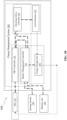
- Figure 1B illustrates a block diagram of the power system 100 deployed in the electric vehicle 106, according to one or more embodiments of the invention.
- the power system 100 for optimizing power supply to the Electrified Transportation Refrigeration Unit (E-TRU) 101 of the electric vehicle 106 includes the energy storage unit 102, the axle generator 103, and a charge management system 104.
- the energy storage unit 102 is configured to supply power to the E-TRU 101.
- a single energy storage unit 102 may be configured to supply power to both the electric vehicle 106 and the E-TRU 101.
- the energy storage unit 102 can be separate for the electric vehicle 106 and the E-TRU 101, for example, one energy storage unit 102 for the electric vehicle 106 and another energy storage unit 102 for powering the E-TRU 101.
- the axle generator 103 may be embodied as an Alternate Current (AC) generator configured to convert the rotational energy into the AC power.
- the axle generator 103 may be asynchronous or synchronous.
- an inverter may be in communication with the axle generator 103 and configured to receive the AC power from the axle generator 103.
- the inverter may be configured to convert the AC power into the Direct Current (DC) power.
- the inverter may include, but is not limited to, a voltage control function, a current control function, and a frequency converter.
- the axle generator 103 may be embodied as a DC generator, without departing from the scope of the invention as set out in the appended claims.
- the charge management system 104 is in communication with the E-TRU 101, the energy storage unit 102, and the axle generator 103.
- the charge management system 104 includes a battery management controller 122 and an E-TRU controller 124 in communication with each other and an electronic drive controller 126 configured to control the axle generator 103.
- the charge management system 104 or more particularly, the battery management controller 122, is configured to monitor a State of Charge (SoC) of the energy storage unit 102.
- SoC State of Charge
- the charge management system 104 accesses route information associated with the electric vehicle 106.
- the route information includes at least one of information retrieved from a Geographical Information System (GIS), information associated with driver behavior, and information retrieved from a sensing system 120 associated with the electric vehicle 106.
- GIS information may be retrieved from a database that contains representations of geographic phenomena, modeling their geometry (location and shape), and their properties or attributes.
- the GIS database may be stored in a variety of forms, such as a collection of separate data files or a single spatially enabled relational database.
- GIS information uses space-time location as the key index variable for all other information. Just as a relational database containing text or numbers can relate many different tables using common key index variables, GIS can relate otherwise unrelated information by using location as the key index variable.
- the key is the location and/or extent in space-time.
- Any variable that can be located spatially, and increasingly also temporally, can be referenced using a GIS.
- Locations or extents in Earth space-time may be recorded as dates/times of occurrence, and x, y, and z coordinates representing, longitude, latitude, and elevation, respectively.
- These GIS coordinates may represent other quantified systems of temporo-spatial reference (for example, highway mile-marker, surveyor benchmark, building address, street intersection, entrance gate, etc.).
- Units applied to recorded temporal-spatial data can vary widely (even when using the same data, see map projections), but all Earth-based spatial-temporal location and extent references should, ideally, be relatable to one another and ultimately to a "real" physical location or extent in space-time.
- mapping references raster images and vector.
- Points, lines, and polygons represent vector data of mapped location attribute references.
- a new hybrid method of storing data is that of identifying point clouds, which combine three-dimensional points with RGB information at each point, returning a "3D color image”.
- the route information may be stored in a memory unit 128.
- the driver of the electric vehicle 106 may select a route from a current location to a destination where the driver wishes to reach.
- the charge management system 104 may retrieve the route information from the memory unit 128 which is deployed as a part of the charge management system 104 or deployed in a remote server.
- the route information includes information regarding the elevation along different sections of the route, the number of turns or hairpin bends, the traffic information, the number of designated stops, etc.
- the information associated with driver behaviour is also stored for different driver profiles in the memory unit 128. The information associated with driver behavior may be determined in real time based on input signals from the sensing system 120.
- the reference driver behaviour is learned using instantaneous and/or historical route information retrieved from the memory unit 128 using an AI-dedicated processor such as a neural processing unit (NPU).
- the one or a plurality of processors control the processing of the input data in accordance with a predefined operating rule or artificial intelligence (AI) model stored in the non-volatile memory and the volatile memory.
- the predefined operating rule or artificial intelligence model is provided through training or learning.
- the sensing system 120 includes a plurality of sensors, such as, but not limited to, temperature sensors configured to detect a temperature within the E-TRU 101, speed sensors configured to detect a speed of the electric vehicle 106, etc. Moreover, the sensing system 120 may include sensors configured to detect vehicle speed, clutch switch, brake switch, cruise control, accelerator pedal position, engine speed and generate input signals that are transmitted to the battery management controller 122. In one or more embodiments according to the invention, the information retrieved from the sensing system 120 comprises information associated with detection of at least one of an acceleration condition, a de-acceleration condition, a coasting condition, and a braking condition, and an idling condition of the electric vehicle 106.
- the information retrieved from the sensing system 120 comprises information associated with detection of at least one of an acceleration condition, a de-acceleration condition, a coasting condition, and a braking condition, and an idling condition of the electric vehicle 106.
- the one or a plurality of processors control the processing of the input data in accordance with a predefined operating rule or artificial intelligence (AI) model stored in the non-volatile memory and the volatile memory.
- the predefined operating rule or artificial intelligence model is provided through training or learning.
- the method 200 includes predicting, via the charge management system 104, a power requirement of at least the E-TRU 101 based on the accessed route information.
- the method 200 includes the step of controlling, via the charge management system 104, the axle generator 103 in at least one of the engaged mode and the disengaged mode based on the monitored SoC and the predicted power requirement of at least the E-TRU 101.
- the power system 100 and method 200 provide an improved energy management by leveraging the GIS information, information from the sensing system 120, and driver behaviour information to improve the utilization of the energy storage unit 102 thereby increasing the efficiency of the E-TRU 101, optimizing energy consumption, and increasing life of the overall system.
- Optimal consumption of the energy storage unit 102 and the axle generator 103 is achieved which increases the efficiency of the E-TRU 101. Therefore, the power system 100 and method 200 disclosed herein, help in optimizing energy, improving reliability, and increasing efficiency throughout the refrigerated transport sector.
Landscapes
- Engineering & Computer Science (AREA)
- Power Engineering (AREA)
- Mechanical Engineering (AREA)
- Physics & Mathematics (AREA)
- Thermal Sciences (AREA)
- Transportation (AREA)
- Life Sciences & Earth Sciences (AREA)
- Sustainable Development (AREA)
- Sustainable Energy (AREA)
- Health & Medical Sciences (AREA)
- Public Health (AREA)
- Electric Propulsion And Braking For Vehicles (AREA)
Applications Claiming Priority (1)
| Application Number | Priority Date | Filing Date | Title |
|---|---|---|---|
| US202463616989P | 2024-01-02 | 2024-01-02 |
Publications (1)
| Publication Number | Publication Date |
|---|---|
| EP4582284A1 true EP4582284A1 (de) | 2025-07-09 |
Family
ID=93925344
Family Applications (1)
| Application Number | Title | Priority Date | Filing Date |
|---|---|---|---|
| EP24220809.8A Pending EP4582284A1 (de) | 2024-01-02 | 2024-12-17 | Stromversorgungssystem und verfahren zur optimierung der stromversorgung einer elektrifizierten transportkühleinheit (e-tru) |
Country Status (3)
| Country | Link |
|---|---|
| US (1) | US20250214442A1 (de) |
| EP (1) | EP4582284A1 (de) |
| CN (1) | CN120245722A (de) |
Families Citing this family (1)
| Publication number | Priority date | Publication date | Assignee | Title |
|---|---|---|---|---|
| US20250112491A1 (en) * | 2023-09-29 | 2025-04-03 | Carrier Corporation | Power system for transportation refrigeration unit and method for controlling power thereof |
Citations (3)
| Publication number | Priority date | Publication date | Assignee | Title |
|---|---|---|---|---|
| US20210213805A1 (en) * | 2018-09-28 | 2021-07-15 | Carrier Corporation | Transportation refrigeration unit with external dc generator power source |
| US20230243314A1 (en) * | 2022-01-28 | 2023-08-03 | Carrier Corporation | Power system for a transport refrigeration unit |
| US20230278392A1 (en) * | 2022-03-01 | 2023-09-07 | Carrier Corporation | Proactive adjustment of transport refrigeration units |
Family Cites Families (4)
| Publication number | Priority date | Publication date | Assignee | Title |
|---|---|---|---|---|
| GB202008254D0 (en) * | 2020-06-02 | 2020-07-15 | Sunswap Ltd | Electric mobile refrigeration unit |
| US11840157B2 (en) * | 2021-07-19 | 2023-12-12 | Rivian Ip Holdings, Llc | Charge time estimation |
| EP4321355A1 (de) * | 2022-08-08 | 2024-02-14 | Thermo King LLC | Gerät mit einem photovoltaischen system |
| EP4325682A1 (de) * | 2022-08-17 | 2024-02-21 | Thermo King LLC | Vorrichtung mit einem wechselrichter |
-
2024
- 2024-12-17 EP EP24220809.8A patent/EP4582284A1/de active Pending
- 2024-12-19 US US18/987,153 patent/US20250214442A1/en active Pending
-
2025
- 2025-01-02 CN CN202510001841.2A patent/CN120245722A/zh active Pending
Patent Citations (3)
| Publication number | Priority date | Publication date | Assignee | Title |
|---|---|---|---|---|
| US20210213805A1 (en) * | 2018-09-28 | 2021-07-15 | Carrier Corporation | Transportation refrigeration unit with external dc generator power source |
| US20230243314A1 (en) * | 2022-01-28 | 2023-08-03 | Carrier Corporation | Power system for a transport refrigeration unit |
| US20230278392A1 (en) * | 2022-03-01 | 2023-09-07 | Carrier Corporation | Proactive adjustment of transport refrigeration units |
Also Published As
| Publication number | Publication date |
|---|---|
| US20250214442A1 (en) | 2025-07-03 |
| CN120245722A (zh) | 2025-07-04 |
Similar Documents
| Publication | Publication Date | Title |
|---|---|---|
| US10787165B2 (en) | Hybrid vehicle and method of changing operation mode for the same | |
| Zhang et al. | Role of terrain preview in energy management of hybrid electric vehicles | |
| WO2022007689A1 (zh) | 车辆的充电提醒方法、设备、程序、存储介质及车辆 | |
| CN118597091B (zh) | 新能源车辆能量智能管理方法、系统及相关设备 | |
| US20110309926A1 (en) | Method and system for determining a route for efficient energy consumption | |
| JP6898714B2 (ja) | 電気トラックの走行ルート選定システム、電気トラックの走行ルート選定方法 | |
| US12497013B2 (en) | Electronic mechanical braking method and electronic mechanical braking apparatus | |
| JP2018017671A (ja) | 電気トラックの走行ルート選定システム、電気トラックの走行ルート選定方法 | |
| WO2024103702A1 (zh) | 一种预见性能量管理方法、装置、电子设备及存储介质 | |
| US20130166116A1 (en) | Method and system for power management in a hybrid electric vehicle | |
| EP4582284A1 (de) | Stromversorgungssystem und verfahren zur optimierung der stromversorgung einer elektrifizierten transportkühleinheit (e-tru) | |
| EP4381244A1 (de) | Verfahren und systeme zur vorhersage eines energieverbrauchs eines fahrzeugs für seine fahrt entlang einer definierten route und zur weglenkung | |
| WO2021249421A1 (zh) | 驾驶模式控制方法、装置、设备、程序和介质 | |
| EP4215875B1 (de) | Verarbeitungseinheit und verfahren zum ermöglichen einer zuverlässigen reichweitenschätzung für ein fahrzeug entlang einer route | |
| CN110936947A (zh) | 一种混合动力汽车的控制方法、装置、设备及介质 | |
| JP6936827B2 (ja) | 電気トラックの走行ルート選定システム、電気トラックの走行ルート選定方法 | |
| US20190302877A1 (en) | Method of controlling a vehicle to adjust perception system energy usage | |
| US12385758B2 (en) | Location-synchronous averaging of connected vehicle data | |
| CN116022123B (zh) | 节能控制方法、装置及电子设备 | |
| JP2018025401A (ja) | 電気トラックの走行ルート選定システム、電気トラックの走行ルート選定方法 | |
| US20250162420A1 (en) | System and method for managing power supplied to atransportation refrigeration unit (tru) | |
| US20260072445A1 (en) | Control systems for autonomous vehicle deployment and vehicle cooling priority | |
| EP4530114A1 (de) | Stromversorgungssystem für transportkühleinheit und verfahren zur steuerung von dessen leistung | |
| US20160140780A1 (en) | System and method of calculating distance to empty of eco-friendly vehicle | |
| CN119283721B (zh) | 车辆里程预测方法、车辆里程预测装置、车辆和存储介质 |
Legal Events
| Date | Code | Title | Description |
|---|---|---|---|
| PUAI | Public reference made under article 153(3) epc to a published international application that has entered the european phase |
Free format text: ORIGINAL CODE: 0009012 |
|
| STAA | Information on the status of an ep patent application or granted ep patent |
Free format text: STATUS: THE APPLICATION HAS BEEN PUBLISHED |
|
| AK | Designated contracting states |
Kind code of ref document: A1 Designated state(s): AL AT BE BG CH CY CZ DE DK EE ES FI FR GB GR HR HU IE IS IT LI LT LU LV MC ME MK MT NL NO PL PT RO RS SE SI SK SM TR |
|
| STAA | Information on the status of an ep patent application or granted ep patent |
Free format text: STATUS: REQUEST FOR EXAMINATION WAS MADE |
|
| 17P | Request for examination filed |
Effective date: 20260108 |