EP4157610B1 - Verfahren zur herstellung eines behälters mit einer vorgegebenen form aus folienmaterial - Google Patents
Verfahren zur herstellung eines behälters mit einer vorgegebenen form aus folienmaterial Download PDFInfo
- Publication number
- EP4157610B1 EP4157610B1 EP21730652.1A EP21730652A EP4157610B1 EP 4157610 B1 EP4157610 B1 EP 4157610B1 EP 21730652 A EP21730652 A EP 21730652A EP 4157610 B1 EP4157610 B1 EP 4157610B1
- Authority
- EP
- European Patent Office
- Prior art keywords
- forming
- sheet
- reference axis
- container
- along
- Prior art date
- Legal status (The legal status is an assumption and is not a legal conclusion. Google has not performed a legal analysis and makes no representation as to the accuracy of the status listed.)
- Active
Links
Images


Classifications
-
- B—PERFORMING OPERATIONS; TRANSPORTING
- B29—WORKING OF PLASTICS; WORKING OF SUBSTANCES IN A PLASTIC STATE IN GENERAL
- B29C—SHAPING OR JOINING OF PLASTICS; SHAPING OF MATERIAL IN A PLASTIC STATE, NOT OTHERWISE PROVIDED FOR; AFTER-TREATMENT OF THE SHAPED PRODUCTS, e.g. REPAIRING
- B29C51/00—Shaping by thermoforming, i.e. shaping sheets or sheet like preforms after heating, e.g. shaping sheets in matched moulds or by deep-drawing; Apparatus therefor
- B29C51/04—Combined thermoforming and prestretching, e.g. biaxial stretching
-
- B—PERFORMING OPERATIONS; TRANSPORTING
- B29—WORKING OF PLASTICS; WORKING OF SUBSTANCES IN A PLASTIC STATE IN GENERAL
- B29C—SHAPING OR JOINING OF PLASTICS; SHAPING OF MATERIAL IN A PLASTIC STATE, NOT OTHERWISE PROVIDED FOR; AFTER-TREATMENT OF THE SHAPED PRODUCTS, e.g. REPAIRING
- B29C49/00—Blow-moulding, i.e. blowing a preform or parison to a desired shape within a mould; Apparatus therefor
- B29C49/42—Component parts, details or accessories; Auxiliary operations
- B29C49/4242—Means for deforming the parison prior to the blowing operation
- B29C49/4244—Means for deforming the parison prior to the blowing operation during or after laying preform into the final mould
- B29C49/42454—The mould opening plane being vertical
-
- B—PERFORMING OPERATIONS; TRANSPORTING
- B29—WORKING OF PLASTICS; WORKING OF SUBSTANCES IN A PLASTIC STATE IN GENERAL
- B29C—SHAPING OR JOINING OF PLASTICS; SHAPING OF MATERIAL IN A PLASTIC STATE, NOT OTHERWISE PROVIDED FOR; AFTER-TREATMENT OF THE SHAPED PRODUCTS, e.g. REPAIRING
- B29C49/00—Blow-moulding, i.e. blowing a preform or parison to a desired shape within a mould; Apparatus therefor
- B29C49/42—Component parts, details or accessories; Auxiliary operations
- B29C49/48—Moulds
- B29C49/4802—Moulds with means for locally compressing part(s) of the parison in the main blowing cavity
-
- B—PERFORMING OPERATIONS; TRANSPORTING
- B31—MAKING ARTICLES OF PAPER, CARDBOARD OR MATERIAL WORKED IN A MANNER ANALOGOUS TO PAPER; WORKING PAPER, CARDBOARD OR MATERIAL WORKED IN A MANNER ANALOGOUS TO PAPER
- B31B—MAKING CONTAINERS OF PAPER, CARDBOARD OR MATERIAL WORKED IN A MANNER ANALOGOUS TO PAPER
- B31B50/00—Making rigid or semi-rigid containers, e.g. boxes or cartons
- B31B50/59—Shaping sheet material under pressure
- B31B50/592—Shaping sheet material under pressure using punches or dies
-
- D—TEXTILES; PAPER
- D21—PAPER-MAKING; PRODUCTION OF CELLULOSE
- D21J—FIBREBOARD; MANUFACTURE OF ARTICLES FROM CELLULOSIC FIBROUS SUSPENSIONS OR FROM PAPIER-MACHE
- D21J5/00—Manufacture of hollow articles by transferring sheets, produced from fibres suspensions or papier-mâché by suction on wire-net moulds, to couch-moulds
-
- B—PERFORMING OPERATIONS; TRANSPORTING
- B29—WORKING OF PLASTICS; WORKING OF SUBSTANCES IN A PLASTIC STATE IN GENERAL
- B29C—SHAPING OR JOINING OF PLASTICS; SHAPING OF MATERIAL IN A PLASTIC STATE, NOT OTHERWISE PROVIDED FOR; AFTER-TREATMENT OF THE SHAPED PRODUCTS, e.g. REPAIRING
- B29C2791/00—Shaping characteristics in general
- B29C2791/001—Shaping in several steps
-
- B—PERFORMING OPERATIONS; TRANSPORTING
- B29—WORKING OF PLASTICS; WORKING OF SUBSTANCES IN A PLASTIC STATE IN GENERAL
- B29C—SHAPING OR JOINING OF PLASTICS; SHAPING OF MATERIAL IN A PLASTIC STATE, NOT OTHERWISE PROVIDED FOR; AFTER-TREATMENT OF THE SHAPED PRODUCTS, e.g. REPAIRING
- B29C2791/00—Shaping characteristics in general
- B29C2791/004—Shaping under special conditions
- B29C2791/007—Using fluid under pressure
-
- B—PERFORMING OPERATIONS; TRANSPORTING
- B29—WORKING OF PLASTICS; WORKING OF SUBSTANCES IN A PLASTIC STATE IN GENERAL
- B29K—INDEXING SCHEME ASSOCIATED WITH SUBCLASSES B29B, B29C OR B29D, RELATING TO MOULDING MATERIALS OR TO MATERIALS FOR MOULDS, REINFORCEMENTS, FILLERS OR PREFORMED PARTS, e.g. INSERTS
- B29K2305/00—Use of metals, their alloys or their compounds, as reinforcement
- B29K2305/02—Aluminium
-
- B—PERFORMING OPERATIONS; TRANSPORTING
- B29—WORKING OF PLASTICS; WORKING OF SUBSTANCES IN A PLASTIC STATE IN GENERAL
- B29K—INDEXING SCHEME ASSOCIATED WITH SUBCLASSES B29B, B29C OR B29D, RELATING TO MOULDING MATERIALS OR TO MATERIALS FOR MOULDS, REINFORCEMENTS, FILLERS OR PREFORMED PARTS, e.g. INSERTS
- B29K2311/00—Use of natural products or their composites, not provided for in groups B29K2201/00 - B29K2309/00, as reinforcement
- B29K2311/12—Paper, e.g. cardboard
-
- B—PERFORMING OPERATIONS; TRANSPORTING
- B29—WORKING OF PLASTICS; WORKING OF SUBSTANCES IN A PLASTIC STATE IN GENERAL
- B29L—INDEXING SCHEME ASSOCIATED WITH SUBCLASS B29C, RELATING TO PARTICULAR ARTICLES
- B29L2031/00—Other particular articles
- B29L2031/712—Containers; Packaging elements or accessories, Packages
- B29L2031/7132—Bowls, Cups, Glasses
-
- B—PERFORMING OPERATIONS; TRANSPORTING
- B31—MAKING ARTICLES OF PAPER, CARDBOARD OR MATERIAL WORKED IN A MANNER ANALOGOUS TO PAPER; WORKING PAPER, CARDBOARD OR MATERIAL WORKED IN A MANNER ANALOGOUS TO PAPER
- B31B—MAKING CONTAINERS OF PAPER, CARDBOARD OR MATERIAL WORKED IN A MANNER ANALOGOUS TO PAPER
- B31B2110/00—Shape of rigid or semi-rigid containers
- B31B2110/20—Shape of rigid or semi-rigid containers having a curved cross section, e.g. circular
Definitions
- the present invention regards a process for obtaining a container of a given shape from sheet material, of the type comprising the steps of:
- the process in question is a process of hot forming of the sheet constituting the starting material, where, first, the forming device operates to provide a substantial deformation of the sheet in order to obtain a blank of the container, and then gas under pressure is blown into the forming cavity to model the blank so that it will assume the final shape of the container.
- a problem that arises with complex shapes of the type referred to regards the capacity to guarantee that the sheet will be deformed at the same time preventing any excessive thinning-out in each of the various portions of the container formed, which would render the container subject to lack of structural homogeneity such as to vitiate the mechanical and physical characteristics thereof.
- the object of present invention is to provide a solution that will be improved as compared to the prior art, in particular one that will make it possible to use less material, i.e., a sheet of small thickness, for production of the container.
- the solution described herein regards a process for obtaining a container of a given shape starting from sheet material.
- the type of material used may be of a thermoformable or deformable type, for example plastic resins, paper, polymeric material, aluminium, etc., alone or in combination.
- the solution described herein refers to the field of containers made of polymeric material.
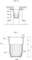
- FIGS. 1A-1E and 2 illustrate an example of application of the solution described herein to obtain a container, designated as a whole by the reference number 100, which has a given height H and extends along the dimension of height, identifying a first portion 100A and a second portion 100B that have a different shape and different dimensions.
- the portion 100A which is located closer to the mouth 100' of the container, has a roughly cylindrical conformation and extends for a height H1.
- the portion 100B which terminates on the bottom of the container, has a smaller cross section with undulated profile and with dimensions that vary along the height H. More in particular, the portion 100B comprises a first stretch 100B' with substantially constant cross section, and a second stretch 100B" with cross section decreasing downwards. As a whole, the portion 100B extends for a height H2.
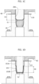
- the step of insertion of the sheet 110 into the forming cavity 20A by the forming device 40 envisages at least two distinct steps ( Figures 1C and 1D ).
- the sheet 110 is pushed by a first operating surface S1 of a forming member, which approximates, as regards dimensions, the section of the portion 100A of the container, and is inserted into the forming cavity 20A for a stretch substantially corresponding to the height H1 of the portion 100A ( Figure 1C ).
- the sheet 110 is pushed by a second operating surface S2 of a forming member, smaller than the surface S1, which approximates, as regards dimensions, the smaller section of the portion 100B of the container, and is further inserted into the forming cavity 20A for a stretch substantially corresponding to the height H2 of the portion 100B ( Figure 1D ).
- the surfaces S1 and S2 operate on the sheet coming completely into contact therewith.
- the container blank 101 obtained has two portions distinct from one another 101A, 101B, which reproduce, in a rough and approximate way, the portions 100A, 100B of the container.
- the next step of the process which envisages blowing gas under pressure into the forming cavity, completes forming of the sheet 110 urging it against the entire inner surface of the forming cavity 20A so that it assumes the exact same shape thereof, which corresponds to the shape of the container 100 ( Figure 1E ) .
- the step of preliminary forming of the sheet by the forming device 40 may also envisage a number of steps greater than two, on the basis of the shape of the container to be obtained; the step in question may for example envisage three or four steps, and use of a corresponding number of operating surfaces, of dimensions progressively decreasing from one step to the next, as described above.
- the present applicant has been able to verify that execution, in the two (or more) distinct steps referred to, of the step of forming of the sheet by the forming device 40 makes it possible to improve the degree of homogeneity of the structure of the container 100.
- the differences of thickness in the different points of the container are considerably smaller than those that can be found in containers obtained via conventional forming processes.
- the present applicant has in any case reason to believe that the effect found of a greater homogeneity of the structure of the container can be put down to the fact that the division of the process of deformation of the sheet into two (or more) distinct steps, of which the first step is carried out via an operating surface S1 greater than that of the second step (and that of the further steps, if these are envisaged), makes it possible to distribute the sheet material, in terms of thickness, in a more uniform way between the top and bottom portions of the container formed. In this way, formation, in the container, of portions that are considerably thinner and weaker or more brittle than others is prevented.
- the greater degree of homogeneity of the structure of the container obtained evidently constitutes an improvement of the quality of the container itself and moreover affords a prolongation of the shelf life of the end product.
- the process described herein hence leads to benefits in terms of saving of material, reduction in the production costs, and reduction of the environmental impact of the containers obtained. Moreover, the process described herein makes it possible to use new materials that cannot be used with conventional processes and to provide shapes that up to now have been difficult to obtain with current systems.
- the process described herein can be used for providing containers of any shape so that the shape of the container is not to be understood as in any way limiting the inventive solution disclosed herein.
- the shapes, dimensions, and dimensional ratios of the two surfaces S1 and S2 may be selected according to the specific applications.
- the process described herein may envisage preheating of the sheet to be formed or else cold execution of the steps of forming the sheet, this according to the type of material (thermoformable or deformable) constituting the sheet and/or the shape of the container to be obtained.
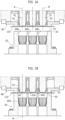
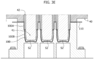
- FIGS 3A-3E these illustrate in greater detail the forming means of the forming device 40 and modes of operation thereof according to a preferred embodiment of the solution described herein.
- the process may in any case envisage the use of forming means different from the ones illustrated hereinafter.
- the forming device 40 comprises a first forming member 41 and a second forming member 42, which are mounted inside one another in a telescopic way and are prearranged for co-operating with the forming cavity 20A of the mould 20.
- the example illustrated in the figures regards an application in which the mould 20 is provided with a plurality of forming cavities 20A and, likewise, the forming device 40 is provided with a corresponding number of pairs of forming members 41, 42 designed to co-operate with the plurality of cavities 20A.
- the two members 41, 42 are mobile along the reference axis R, both fixedly and according to a relative motion, for carrying out the two distinct steps illustrated above of the step of forming the sheet via the device 40.
- the two members 41, 42 move into a condition where the ends 41A, 42A thereof are substantially aligned to form as a whole the first operating surface S1 mentioned above ( Figure 3B ).
- the end 42A of the outer member 42 has a substantially conical conformation and, in the condition mentioned, sets itself in a position slightly set back with respect to the end 41A of the forming member 41, so as to constitute an ideal prolongation of the chamfered perimetral edge of the end 41A.
- the effective area, which is important for the action discussed herein, of the operating surface S1 is represented by its projection in a plane orthogonal to the reference axis R.
- the two members 41, 42 approach the sheet 110, which is gripped between a top surface 23 of the mould 20 and a bottom surface 43 of the forming device 40 and push it by way of the operating surface S1 into the forming cavity 20A, for a first stretch of length substantially corresponding to the height H1 ( Figure 3C ).
- the portion 101A of the container blank 101 is thus formed on the sheet 110.
- the forming member 41 alone performs a further movement along the reference axis R, for a stretch of length substantially corresponding to the height H2 until it reaches the bottom of the forming cavity 20A ( Figure 3D ). During this movement of the member 41, the member 42 remains stationary in the position reached at the end of the first step.
- Movement of the member 41 enables extraction thereof from the outer member 42, and the member 41 thus performs, by itself, an action of thrust on the sheet 110 through its end 41A, which defines the operating surface S2 referred to above for the second step.
- the operating surface S2 evidently has an effective area, with respect to an action of thrust along the reference axis R, that is smaller than that of the surface S1, being defined by just the inner member 41.
- the action of the member 41 enables formation of the portion 101B of the container blank 101 and corresponds to the second step of the forming process.
- the blowing step can in any case also be started during the first movement of the two forming bodies 41, 42 or else during the second movement of just the forming body 41, this according to the specific applications.
- This step can be performed according to conventional modalities, so that further details are not provided herein.
- the two forming members 41, 42 are associated to a driving system that is able to activate the two members simultaneously or separately as illustrated above.
- the driving system mentioned may comprise two independent driving devices, each for governing one of the two forming members 41, 42.
- the process described herein may envisage forming means different from the ones illustrated above.
- two forming members coupled together and co-operating in the way illustrated above
- two independent forming members one of which defines the operating surface S1 and the other the operating surface S2.
- the mutual arrangement of the two members 41 and 42 may vary according to the specific applications, in particular according to the particular shapes of the containers to be obtained.
- the two members 41 and 42 could be arranged simply alongside one another and not mounted inside one another.
- the forming device 40 comprises a thermalconditioning system (heating or cooling means), associated to one or both of the forming members 41, 42, to keep the corresponding ends 41A, 42A at pre-set temperatures.
- This system may, for example, include an electrical resistance and a thermostat for controlling electrical supply to the resistance.
- a preferred application of the process described herein regards production of containers in aseptic environment.
Landscapes
- Engineering & Computer Science (AREA)
- Mechanical Engineering (AREA)
- Manufacturing & Machinery (AREA)
- Blow-Moulding Or Thermoforming Of Plastics Or The Like (AREA)
- Making Paper Articles (AREA)
- Cartons (AREA)
Claims (8)
- Verfahren zum Herstellen eines Behälters (100) mit einer vorgegebenen Form aus einem Plattenmaterial, das die folgenden Schritte umfasst:- Vorsehen einer Platte (110);- Vorsehen einer Form (20) mit einem Formungshohlraum (20A), der eine Bezugsachse (R) definiert und eine Form hat, die der vorgegebenen Form des Behälters (100) entspricht;- Positionieren der Platte (110) über dem Formungshohlraum (20A)- Vorsehen einer Formungsvorrichtung (40) mit Formungsmitteln (41, 42), die auf der Seite der Platte angeordnet sind, die dem Formungshohlraum gegenüberliegt, und Betätigen der Formungsmittel zum Einbringen der Platte (110) in den Formungshohlraum (20A), um sie zu verformen, bis ein Behälterrohling (101) erhalten wird, der eine Form aufweist, die der vorgegebenen Form nahekommt; und- Einblasen eines Gases unter Druck in den Formungshohlraum (20A), um den Behälterrohling (101) zu verformen, bis der Behälter (100) mit der vorgegebenen Form erhalten wird;wobei der Schritt des Einbringens der Platte (110) in den Formungshohlraum Folgendes umfasst:- In-Kontakt-Bringen einer ersten Arbeitsfläche (S1) eines Formungselements (41, 42) mit der Platte und Drücken der Platte (110) mittels der ersten Arbeitsfläche (S1) in den Formungshohlraum (20A) für eine erste Strecke (H1) entlang der Referenzachse (R); und- ferner Drücken der Platte (110) mittels einer zweiten Arbeitsfläche (S2) eines Formungselements (41, 42), die kleiner ist als die erste Fläche (S1), in den Formungshohlraum (20A) für eine zweite Strecke (H2) entlang der Referenzachse (R), dadurch gekennzeichnet, dassdie Formungsvorrichtung (40) ein erstes Formungselement (41) und ein zweites Formungselement (42) umfasst, die entlang der Referenzachse (R) getrennt oder gleichzeitig angetrieben werden können,wobei das Verfahren Folgendes umfasst:- Einstellen des ersten und des zweiten Formungselements (41, 42) im Wesentlichen in ein und dieselbe Position entlang der Referenzachse (R), sodass sie zusammen die erste Arbeitsfläche (S1) definieren;- Zuführen des ersten und zweiten Formungselements (41, 42) in diesem Zustand in einer fixierten Weise in Bezug zueinander entlang der Referenzachse (R) für die erste Strecke (H1); und- Halten des ersten Formungselements (42) stationär und weiter Vorschieben des zweiten Formungselements (41) entlang der Referenzachse (R) für die zweite Strecke (H2), wobei ein Ende (41A) des zweiten Elements die zweite Arbeitsfläche (S2) definiert.
- Verfahren nach Anspruch 1, wobei in der Formungsvorrichtung (40):- das erste und das zweite Formungselement (41, 42) teleskopartig ineinander montiert sind; und- das erste Formungselement (42) eine röhrenförmige Gestalt und das zweite Formungselement (41) eine zylindrische Gestalt aufweist, wobei die entsprechenden Achsen des ersten und des zweiten Elements (41, 42) mit der Bezugsachse ausgerichtet sind; wobei das Verfahren Folgendes umfasst:- Positionieren entsprechender Enden (41A, 42A) des ersten und zweiten Formungselements (41, 42), die dem Formungshohlraum (20A) zugewandt sind, im Wesentlichen in ein und derselben Position entlang der Referenzachse (R), um die erste Arbeitsfläche (S1) zu bilden,- Vorschieben des ersten und zweiten Formungselements (41, 42) in diesem Zustand entlang der Referenzachse (R) in einer fixierten Weise in Bezug zueinander für die erste Strecke (H1); und- Halten des ersten Formungselements (42) stationär und Vorschieben des zweiten Formungselements (41) weiter entlang der Referenzachse (R) für die zweite Strecke (H2), um das zweite Formungselement (41) dazu zu bringen, aus dem ersten Formungselement (42) herauszuragen.
- Verfahren nach Anspruch 1 oder 2, welches Einblasen von Gas in den Formungshohlraum (20A) in einem Zustand umfasst, in dem das erste Formungselement (42) am Ende der ersten Strecke (H1) positioniert ist und das zweite Formungselement (41) am Ende der zweiten Strecke (H2) positioniert ist; und/oder Einblasen von Gas in den Formungshohlraum (20A) während der Bewegung des ersten und zweiten Formungselements (42, 41) entlang der ersten Strecke (Hl); und/oder
Einblasen von Gas in den Formungshohlraum (20A) während der Bewegung des zweiten Formungselements (41) entlang der zweiten Strecke (H2). - Verfahren nach einem der vorhergehenden Ansprüche, das Folgendes umfasst:- Vorsehen eines ersten Abschnitts (101A) des Behälterrohlings (101) durch die erste Arbeitsfläche (S1), der sich entlang der ersten Strecke (H1) erstreckt und einen Querschnitt aufweist, der durch die erste Arbeitsfläche (S1) bestimmt wird; und- Vorsehen eines zweiten Abschnitts (101B) des Behälterrohlings (101) durch die zweite Arbeitsfläche (S2), der sich entlang der zweiten Strecke (H2) erstreckt und einen Querschnitt aufweist, der durch die zweite Arbeitsfläche (S2) bestimmt ist,wobei der Querschnitt quer zu der Referenzachse (R) des ersten Abschnitts (101A) größer ist als der Querschnitt des zweiten Abschnitts (101B).
- Verfahren nach einem der vorhergehenden Ansprüche, wobei entlang der Referenzachse (R) eine gegebene Höhe des Behälters (100) bestimmt wird, die zwischen seinem Öffnungsrand (100') und seinem Boden liegt, und wobei an dem Behälter (100) entlang der Referenzachse (R) ein erster Abschnitt (100A) und ein zweiter Abschnitt (100B) bestimmt werden, die voneinander verschieden sind, wobei der erste Abschnitt (100A) einen Querschnitt quer zur Referenzachse (R) aufweist, der größer ist als der Querschnitt des zweiten Abschnitts (100B).
- Verfahren nach einem der vorhergehenden Ansprüche, wobei die Platte aus einem thermoformbaren oder verformbaren Material, vorzugsweise aus Kunststoffharzen, Papier, Polymermaterial, Aluminium usw., allein oder in Kombination hergestellt werden kann.
- Verfahren nach einem der vorhergehenden Ansprüche, wobei die Platte vor den Formungsschritten erwärmt wird.
- Verfahren nach einem der Ansprüche 1 bis 3, wobei die Formungsvorrichtung (40) ein Wärmekonditionierungssystem umfasst, um die ersten Formungselemente (41) und/oder das zweite Formungselement (42) auf einer voreingestellten Temperatur zu halten.
Applications Claiming Priority (2)
| Application Number | Priority Date | Filing Date | Title |
|---|---|---|---|
| IT102020000012772A IT202000012772A1 (it) | 2020-05-28 | 2020-05-28 | Procedimento per realizzare un contenitore di una data forma da materiale in foglio |
| PCT/IB2021/054002 WO2021240280A1 (en) | 2020-05-28 | 2021-05-11 | Process for making a container of a given shape from sheet material |
Publications (2)
| Publication Number | Publication Date |
|---|---|
| EP4157610A1 EP4157610A1 (de) | 2023-04-05 |
| EP4157610B1 true EP4157610B1 (de) | 2024-11-27 |
Family
ID=72087055
Family Applications (1)
| Application Number | Title | Priority Date | Filing Date |
|---|---|---|---|
| EP21730652.1A Active EP4157610B1 (de) | 2020-05-28 | 2021-05-11 | Verfahren zur herstellung eines behälters mit einer vorgegebenen form aus folienmaterial |
Country Status (5)
| Country | Link |
|---|---|
| US (1) | US12491674B2 (de) |
| EP (1) | EP4157610B1 (de) |
| CA (1) | CA3179996A1 (de) |
| IT (1) | IT202000012772A1 (de) |
| WO (1) | WO2021240280A1 (de) |
Families Citing this family (1)
| Publication number | Priority date | Publication date | Assignee | Title |
|---|---|---|---|---|
| DE102024119499A1 (de) * | 2024-07-09 | 2026-01-15 | Krones Aktiengesellschaft | Vorrichtung und Verfahren zur Vorbehandlung von Verpackungszuschnitten sowie Verpackungsvorrichtung zur Herstellung von Verpackungseinheiten |
Family Cites Families (6)
| Publication number | Priority date | Publication date | Assignee | Title |
|---|---|---|---|---|
| US5366685A (en) * | 1989-07-18 | 1994-11-22 | Idemitsu Petrochemical Co., Ltd. | Process of molding thermoplastic sheet by plug assist vacuum forming |
| JPH05253965A (ja) * | 1991-09-19 | 1993-10-05 | Toppan Printing Co Ltd | 多層薄肉容器及びその容器の製造方法 |
| DE20319528U1 (de) * | 2003-12-16 | 2004-03-04 | Marbach Werkzeugbau Gmbh | Thermoformwerkzeug |
| ITMO20040034A1 (it) * | 2004-02-16 | 2004-05-16 | Benco Pack Spa | Formatura di contenitori |
| KR101588155B1 (ko) * | 2013-01-09 | 2016-01-22 | 신닛테츠스미킨 카부시키카이샤 | 프레스 성형 방법 |
| ITUB20153650A1 (it) * | 2015-09-28 | 2017-03-28 | Aroma System Srl | Macchina per termoformatura e metodo di termoformatura |
-
2020
- 2020-05-28 IT IT102020000012772A patent/IT202000012772A1/it unknown
-
2021
- 2021-05-11 WO PCT/IB2021/054002 patent/WO2021240280A1/en not_active Ceased
- 2021-05-11 EP EP21730652.1A patent/EP4157610B1/de active Active
- 2021-05-11 CA CA3179996A patent/CA3179996A1/en active Pending
- 2021-05-11 US US17/927,489 patent/US12491674B2/en active Active
Also Published As
| Publication number | Publication date |
|---|---|
| WO2021240280A1 (en) | 2021-12-02 |
| US12491674B2 (en) | 2025-12-09 |
| CA3179996A1 (en) | 2021-12-02 |
| EP4157610A1 (de) | 2023-04-05 |
| US20230202092A1 (en) | 2023-06-29 |
| IT202000012772A1 (it) | 2021-11-28 |
Similar Documents
| Publication | Publication Date | Title |
|---|---|---|
| US6442988B1 (en) | Methods of spin forming initially cylindrical containers and the like | |
| CA2947446C (en) | Blow moulded container and manufacture thereof | |
| NL8102600A (nl) | Buisvormig uitgangsvoorwerp, alsmede werkwijze en inrichting voor de vervaardiging daarvan. | |
| EP3224018B1 (de) | Verfahren und vorrichtung zur herstellung eines kunststoffbehälters mit gewelltem rand | |
| CN114212971B (zh) | 一种玻璃瓶的吹制方法 | |
| US12491674B2 (en) | Process for making a container of a given shape from sheet material | |
| GB2067952A (en) | Moulding an article from a parison of plastics material | |
| CN107107452A (zh) | 生产热成型产品的方法、用于执行该方法的安装装置和机器 | |
| EP0072832A1 (de) | Herstellung von hohlkörpern durch streckformen einer kunststoffolie | |
| US10076867B2 (en) | Method and device for the production of an optimized bottom contour on preforms | |
| CN114309428A (zh) | 一种大型曲拐曲颈锻造工艺 | |
| CN112496221A (zh) | 一种铝合金件锻压工艺 | |
| EP3037392A2 (de) | Glasprodukt mit geformtem stiel sowie verfahren und vorrichtung zu dessen herstellung | |
| US4243401A (en) | Apparatus for producing double-walled heat insulating containers | |
| JPS62152718A (ja) | 圧力吸収パネルを備えた合成樹脂製瓶の成形方法と装置 | |
| US3375551A (en) | Apparatus for making an open-end container having a curled rim | |
| US20110086749A1 (en) | Manufacturing machine for plastic containers | |
| CN103201187B (zh) | 用于制造包括凹槽的制品的方法,以及制品 | |
| JP6200930B2 (ja) | 一次成形品の二次成形方法及び二次成形装置 | |
| JP2017024193A (ja) | ブロー成形装置、ブロー成形品およびブロー成形方法 | |
| TWI763949B (zh) | 彎曲成形模具 | |
| JP2914521B2 (ja) | 2軸延伸ブロー成形方法 | |
| JPH051730B2 (de) | ||
| RU2473423C2 (ru) | Способ изготовления металлополимерного или биполимерного изделия | |
| JP2019151123A (ja) | ブロー成形法により製造されたプラスチックボトル |
Legal Events
| Date | Code | Title | Description |
|---|---|---|---|
| STAA | Information on the status of an ep patent application or granted ep patent |
Free format text: STATUS: UNKNOWN |
|
| STAA | Information on the status of an ep patent application or granted ep patent |
Free format text: STATUS: THE INTERNATIONAL PUBLICATION HAS BEEN MADE |
|
| PUAI | Public reference made under article 153(3) epc to a published international application that has entered the european phase |
Free format text: ORIGINAL CODE: 0009012 |
|
| STAA | Information on the status of an ep patent application or granted ep patent |
Free format text: STATUS: REQUEST FOR EXAMINATION WAS MADE |
|
| 17P | Request for examination filed |
Effective date: 20221121 |
|
| AK | Designated contracting states |
Kind code of ref document: A1 Designated state(s): AL AT BE BG CH CY CZ DE DK EE ES FI FR GB GR HR HU IE IS IT LI LT LU LV MC MK MT NL NO PL PT RO RS SE SI SK SM TR |
|
| DAV | Request for validation of the european patent (deleted) | ||
| DAX | Request for extension of the european patent (deleted) | ||
| GRAP | Despatch of communication of intention to grant a patent |
Free format text: ORIGINAL CODE: EPIDOSNIGR1 |
|
| STAA | Information on the status of an ep patent application or granted ep patent |
Free format text: STATUS: GRANT OF PATENT IS INTENDED |
|
| RIC1 | Information provided on ipc code assigned before grant |
Ipc: B21J 5/00 20060101ALI20240605BHEP Ipc: B29C 51/04 20060101AFI20240605BHEP |
|
| INTG | Intention to grant announced |
Effective date: 20240621 |
|
| GRAS | Grant fee paid |
Free format text: ORIGINAL CODE: EPIDOSNIGR3 |
|
| GRAA | (expected) grant |
Free format text: ORIGINAL CODE: 0009210 |
|
| STAA | Information on the status of an ep patent application or granted ep patent |
Free format text: STATUS: THE PATENT HAS BEEN GRANTED |
|
| AK | Designated contracting states |
Kind code of ref document: B1 Designated state(s): AL AT BE BG CH CY CZ DE DK EE ES FI FR GB GR HR HU IE IS IT LI LT LU LV MC MK MT NL NO PL PT RO RS SE SI SK SM TR |
|
| REG | Reference to a national code |
Ref country code: GB Ref legal event code: FG4D |
|
| REG | Reference to a national code |
Ref country code: CH Ref legal event code: EP |
|
| P01 | Opt-out of the competence of the unified patent court (upc) registered |
Free format text: CASE NUMBER: APP_60893/2024 Effective date: 20241113 |
|
| REG | Reference to a national code |
Ref country code: IE Ref legal event code: FG4D |
|
| REG | Reference to a national code |
Ref country code: DE Ref legal event code: R096 Ref document number: 602021022450 Country of ref document: DE |
|
| REG | Reference to a national code |
Ref country code: LT Ref legal event code: MG9D |
|
| REG | Reference to a national code |
Ref country code: NL Ref legal event code: MP Effective date: 20241127 |
|
| PG25 | Lapsed in a contracting state [announced via postgrant information from national office to epo] |
Ref country code: IS Free format text: LAPSE BECAUSE OF FAILURE TO SUBMIT A TRANSLATION OF THE DESCRIPTION OR TO PAY THE FEE WITHIN THE PRESCRIBED TIME-LIMIT Effective date: 20250327 Ref country code: HR Free format text: LAPSE BECAUSE OF FAILURE TO SUBMIT A TRANSLATION OF THE DESCRIPTION OR TO PAY THE FEE WITHIN THE PRESCRIBED TIME-LIMIT Effective date: 20241127 Ref country code: PT Free format text: LAPSE BECAUSE OF FAILURE TO SUBMIT A TRANSLATION OF THE DESCRIPTION OR TO PAY THE FEE WITHIN THE PRESCRIBED TIME-LIMIT Effective date: 20250327 |
|
| PG25 | Lapsed in a contracting state [announced via postgrant information from national office to epo] |
Ref country code: FI Free format text: LAPSE BECAUSE OF FAILURE TO SUBMIT A TRANSLATION OF THE DESCRIPTION OR TO PAY THE FEE WITHIN THE PRESCRIBED TIME-LIMIT Effective date: 20241127 Ref country code: NL Free format text: LAPSE BECAUSE OF FAILURE TO SUBMIT A TRANSLATION OF THE DESCRIPTION OR TO PAY THE FEE WITHIN THE PRESCRIBED TIME-LIMIT Effective date: 20241127 |
|
| PG25 | Lapsed in a contracting state [announced via postgrant information from national office to epo] |
Ref country code: BG Free format text: LAPSE BECAUSE OF FAILURE TO SUBMIT A TRANSLATION OF THE DESCRIPTION OR TO PAY THE FEE WITHIN THE PRESCRIBED TIME-LIMIT Effective date: 20241127 |
|
| PG25 | Lapsed in a contracting state [announced via postgrant information from national office to epo] |
Ref country code: ES Free format text: LAPSE BECAUSE OF FAILURE TO SUBMIT A TRANSLATION OF THE DESCRIPTION OR TO PAY THE FEE WITHIN THE PRESCRIBED TIME-LIMIT Effective date: 20241127 |
|
| PG25 | Lapsed in a contracting state [announced via postgrant information from national office to epo] |
Ref country code: NO Free format text: LAPSE BECAUSE OF FAILURE TO SUBMIT A TRANSLATION OF THE DESCRIPTION OR TO PAY THE FEE WITHIN THE PRESCRIBED TIME-LIMIT Effective date: 20250227 |
|
| PG25 | Lapsed in a contracting state [announced via postgrant information from national office to epo] |
Ref country code: GR Free format text: LAPSE BECAUSE OF FAILURE TO SUBMIT A TRANSLATION OF THE DESCRIPTION OR TO PAY THE FEE WITHIN THE PRESCRIBED TIME-LIMIT Effective date: 20250228 Ref country code: LV Free format text: LAPSE BECAUSE OF FAILURE TO SUBMIT A TRANSLATION OF THE DESCRIPTION OR TO PAY THE FEE WITHIN THE PRESCRIBED TIME-LIMIT Effective date: 20241127 |
|
| PG25 | Lapsed in a contracting state [announced via postgrant information from national office to epo] |
Ref country code: PL Free format text: LAPSE BECAUSE OF FAILURE TO SUBMIT A TRANSLATION OF THE DESCRIPTION OR TO PAY THE FEE WITHIN THE PRESCRIBED TIME-LIMIT Effective date: 20241127 |
|
| PG25 | Lapsed in a contracting state [announced via postgrant information from national office to epo] |
Ref country code: RS Free format text: LAPSE BECAUSE OF FAILURE TO SUBMIT A TRANSLATION OF THE DESCRIPTION OR TO PAY THE FEE WITHIN THE PRESCRIBED TIME-LIMIT Effective date: 20250227 |
|
| PG25 | Lapsed in a contracting state [announced via postgrant information from national office to epo] |
Ref country code: SM Free format text: LAPSE BECAUSE OF FAILURE TO SUBMIT A TRANSLATION OF THE DESCRIPTION OR TO PAY THE FEE WITHIN THE PRESCRIBED TIME-LIMIT Effective date: 20241127 |
|
| PG25 | Lapsed in a contracting state [announced via postgrant information from national office to epo] |
Ref country code: DK Free format text: LAPSE BECAUSE OF FAILURE TO SUBMIT A TRANSLATION OF THE DESCRIPTION OR TO PAY THE FEE WITHIN THE PRESCRIBED TIME-LIMIT Effective date: 20241127 |
|
| PG25 | Lapsed in a contracting state [announced via postgrant information from national office to epo] |
Ref country code: EE Free format text: LAPSE BECAUSE OF FAILURE TO SUBMIT A TRANSLATION OF THE DESCRIPTION OR TO PAY THE FEE WITHIN THE PRESCRIBED TIME-LIMIT Effective date: 20241127 |
|
| PG25 | Lapsed in a contracting state [announced via postgrant information from national office to epo] |
Ref country code: RO Free format text: LAPSE BECAUSE OF FAILURE TO SUBMIT A TRANSLATION OF THE DESCRIPTION OR TO PAY THE FEE WITHIN THE PRESCRIBED TIME-LIMIT Effective date: 20241127 |
|
| PG25 | Lapsed in a contracting state [announced via postgrant information from national office to epo] |
Ref country code: SK Free format text: LAPSE BECAUSE OF FAILURE TO SUBMIT A TRANSLATION OF THE DESCRIPTION OR TO PAY THE FEE WITHIN THE PRESCRIBED TIME-LIMIT Effective date: 20241127 |
|
| PG25 | Lapsed in a contracting state [announced via postgrant information from national office to epo] |
Ref country code: CZ Free format text: LAPSE BECAUSE OF FAILURE TO SUBMIT A TRANSLATION OF THE DESCRIPTION OR TO PAY THE FEE WITHIN THE PRESCRIBED TIME-LIMIT Effective date: 20241127 |
|
| REG | Reference to a national code |
Ref country code: DE Ref legal event code: R097 Ref document number: 602021022450 Country of ref document: DE |
|
| PG25 | Lapsed in a contracting state [announced via postgrant information from national office to epo] |
Ref country code: SE Free format text: LAPSE BECAUSE OF FAILURE TO SUBMIT A TRANSLATION OF THE DESCRIPTION OR TO PAY THE FEE WITHIN THE PRESCRIBED TIME-LIMIT Effective date: 20241127 |
|
| PLBE | No opposition filed within time limit |
Free format text: ORIGINAL CODE: 0009261 |
|
| STAA | Information on the status of an ep patent application or granted ep patent |
Free format text: STATUS: NO OPPOSITION FILED WITHIN TIME LIMIT |
|
| REG | Reference to a national code |
Ref country code: CH Ref legal event code: L10 Free format text: ST27 STATUS EVENT CODE: U-0-0-L10-L00 (AS PROVIDED BY THE NATIONAL OFFICE) Effective date: 20251008 |
|
| 26N | No opposition filed |
Effective date: 20250828 |
|
| REG | Reference to a national code |
Ref country code: CH Ref legal event code: H13 Free format text: ST27 STATUS EVENT CODE: U-0-0-H10-H13 (AS PROVIDED BY THE NATIONAL OFFICE) Effective date: 20251223 |
|
| PG25 | Lapsed in a contracting state [announced via postgrant information from national office to epo] |
Ref country code: LU Free format text: LAPSE BECAUSE OF NON-PAYMENT OF DUE FEES Effective date: 20250511 |
|
| PG25 | Lapsed in a contracting state [announced via postgrant information from national office to epo] |
Ref country code: CH Free format text: LAPSE BECAUSE OF NON-PAYMENT OF DUE FEES Effective date: 20250531 |
|
| GBPC | Gb: european patent ceased through non-payment of renewal fee |
Effective date: 20250511 |
|
| REG | Reference to a national code |
Ref country code: BE Ref legal event code: MM Effective date: 20250531 |
|
| PG25 | Lapsed in a contracting state [announced via postgrant information from national office to epo] |
Ref country code: MC Free format text: LAPSE BECAUSE OF FAILURE TO SUBMIT A TRANSLATION OF THE DESCRIPTION OR TO PAY THE FEE WITHIN THE PRESCRIBED TIME-LIMIT Effective date: 20241127 |
|
| PG25 | Lapsed in a contracting state [announced via postgrant information from national office to epo] |
Ref country code: GB Free format text: LAPSE BECAUSE OF NON-PAYMENT OF DUE FEES Effective date: 20250511 |
|
| PG25 | Lapsed in a contracting state [announced via postgrant information from national office to epo] |
Ref country code: IE Free format text: LAPSE BECAUSE OF NON-PAYMENT OF DUE FEES Effective date: 20250511 |
|
| PG25 | Lapsed in a contracting state [announced via postgrant information from national office to epo] |
Ref country code: BE Free format text: LAPSE BECAUSE OF NON-PAYMENT OF DUE FEES Effective date: 20250531 |
|
| REG | Reference to a national code |
Ref country code: AT Ref legal event code: UEP Ref document number: 1745322 Country of ref document: AT Kind code of ref document: T Effective date: 20241127 |
|
| PG25 | Lapsed in a contracting state [announced via postgrant information from national office to epo] |
Ref country code: LT Free format text: LAPSE BECAUSE OF FAILURE TO SUBMIT A TRANSLATION OF THE DESCRIPTION OR TO PAY THE FEE WITHIN THE PRESCRIBED TIME-LIMIT Effective date: 20241127 |
|
| PGFP | Annual fee paid to national office [announced via postgrant information from national office to epo] |
Ref country code: IT Payment date: 20260504 Year of fee payment: 6 |
|
| PGFP | Annual fee paid to national office [announced via postgrant information from national office to epo] |
Ref country code: DE Payment date: 20260522 Year of fee payment: 6 |
|
| PGFP | Annual fee paid to national office [announced via postgrant information from national office to epo] |
Ref country code: AT Payment date: 20260519 Year of fee payment: 6 |
|
| PGFP | Annual fee paid to national office [announced via postgrant information from national office to epo] |
Ref country code: FR Payment date: 20260521 Year of fee payment: 6 |
|
| PG25 | Lapsed in a contracting state [announced via postgrant information from national office to epo] |
Ref country code: CY Free format text: LAPSE BECAUSE OF FAILURE TO SUBMIT A TRANSLATION OF THE DESCRIPTION OR TO PAY THE FEE WITHIN THE PRESCRIBED TIME-LIMIT Effective date: 20241127 |