EP4157424B1 - Mikronadelapplikator - Google Patents
Mikronadelapplikator Download PDFInfo
- Publication number
- EP4157424B1 EP4157424B1 EP21734425.8A EP21734425A EP4157424B1 EP 4157424 B1 EP4157424 B1 EP 4157424B1 EP 21734425 A EP21734425 A EP 21734425A EP 4157424 B1 EP4157424 B1 EP 4157424B1
- Authority
- EP
- European Patent Office
- Prior art keywords
- motor
- fluid product
- air
- applicator according
- microneedles
- Prior art date
- Legal status (The legal status is an assumption and is not a legal conclusion. Google has not performed a legal analysis and makes no representation as to the accuracy of the status listed.)
- Active
Links
Images



Classifications
-
- A—HUMAN NECESSITIES
- A61—MEDICAL OR VETERINARY SCIENCE; HYGIENE
- A61M—DEVICES FOR INTRODUCING MEDIA INTO, OR ONTO, THE BODY; DEVICES FOR TRANSDUCING BODY MEDIA OR FOR TAKING MEDIA FROM THE BODY; DEVICES FOR PRODUCING OR ENDING SLEEP OR STUPOR
- A61M37/00—Other apparatus for introducing media into the body; Percutany, i.e. introducing medicines into the body by diffusion through the skin
- A61M37/0015—Other apparatus for introducing media into the body; Percutany, i.e. introducing medicines into the body by diffusion through the skin by using microneedles
-
- A—HUMAN NECESSITIES
- A61—MEDICAL OR VETERINARY SCIENCE; HYGIENE
- A61M—DEVICES FOR INTRODUCING MEDIA INTO, OR ONTO, THE BODY; DEVICES FOR TRANSDUCING BODY MEDIA OR FOR TAKING MEDIA FROM THE BODY; DEVICES FOR PRODUCING OR ENDING SLEEP OR STUPOR
- A61M37/00—Other apparatus for introducing media into the body; Percutany, i.e. introducing medicines into the body by diffusion through the skin
- A61M2037/0007—Other apparatus for introducing media into the body; Percutany, i.e. introducing medicines into the body by diffusion through the skin having means for enhancing the permeation of substances through the epidermis, e.g. using suction or depression, electric or magnetic fields, sound waves or chemical agents
-
- A—HUMAN NECESSITIES
- A61—MEDICAL OR VETERINARY SCIENCE; HYGIENE
- A61M—DEVICES FOR INTRODUCING MEDIA INTO, OR ONTO, THE BODY; DEVICES FOR TRANSDUCING BODY MEDIA OR FOR TAKING MEDIA FROM THE BODY; DEVICES FOR PRODUCING OR ENDING SLEEP OR STUPOR
- A61M37/00—Other apparatus for introducing media into the body; Percutany, i.e. introducing medicines into the body by diffusion through the skin
- A61M37/0015—Other apparatus for introducing media into the body; Percutany, i.e. introducing medicines into the body by diffusion through the skin by using microneedles
- A61M2037/0023—Drug applicators using microneedles
Definitions
- the present invention relates to a microneedle applicator for applying a fluid product to the skin and making it penetrate the skin.
- the field of application of the invention is that of cosmetics, and not that of tattooing.
- the goal is to penetrate a cosmetic product into the skin, not to color the skin.
- this type of cosmetic applicator comprises an application face provided with at least one fluid product outlet and several micro-needles.
- An electric motor is used to vibrate the microneedles, alone or with the application face.
- a fluid reservoir is connected to the fluid outlet.
- the reservoir may or may not be integrated into the applicator. When it is integrated, the question then arises of its filling or replacement.
- the applicator may be removable or include a window or cap to access the reservoir.
- an actuator member is also provided to convey the fluid product from the fluid product reservoir to the fluid product outlet.
- This actuating member is often the one which also controls the motor, which then has a dual function, namely to make the micro-needles vibrate and to convey the fluid product from the reservoir to the application face.
- US 6,558,361 B1 describes an applicator for fluid transport with microneedles. The use of a vibrating motor to deliver a substance is mentioned there.
- the aim of the present invention is to provide a dual-function motor-driven applicator, the reservoir of which is easily replaceable, while providing a simple, efficient and robust connection between the motor and the reservoir. Handling the applicator, and in particular replacing the tank, must not lead to accidental damage to this motor/tank connection.
- the second module can be considered as a cartridge or a refill that is replaced, while the first module with its motor is retained.
- the reservoir has a variable volume, the actuation of the motor acting on the reservoir without mechanical transmission of force to cause a reduction in volume of the reservoir of fluid product, so that part of its contents is discharged towards the outlet of the fluid. fluid product.
- the actuation of the motor acting on the reservoir without mechanical transmission of force to cause a reduction in volume of the reservoir of fluid product, so that part of its contents is discharged towards the outlet of the fluid. fluid product.
- the first module may include an air pump.
- the fluid product reservoir may comprise a movable wall which is also part of an air chamber supplied with pressurized air from the air pump.
- the air chamber is formed jointly by the two modules connected in a sealed manner.
- the transmission can therefore be hydraulic, as opposed to mechanical. It is air under pressure in the air chamber which will push and move the movable wall of the tank, which can for example be in the form of a pushing piston or a flexible pocket. The trick is to form this air chamber between the two modules, so that there is no part or mechanical transmission member which is accessible and therefore damaged, when the two modules are separated from one another. the other. All you have to do is create a seal between the two modules to form the inner tube.
- the air pump may comprise a pump chamber provided with an air inlet valve and an air outlet valve connected to the air chamber, the variation in volume of the pump chamber being advantageously provided by a bellows.
- the bellows can be replaced by a piston sliding in a barrel.
- the air inlet valve can be driven axially back and forth by the motor.
- the motor can comprise an axial shaft driven in rotation, a system for transforming rotary movement into axial being mounted on the rotating shaft.
- the air pump can comprise a piston movable axially back and forth under the action of the motor, this piston forming a seat for the air inlet valve, a support for a bellows and transmission means to drive the microneedles of the second module into vibration.
- a purely rotary movement is transformed into a back-and-forth vibratory movement to activate an air pump which sends air under pressure into an air chamber common to the two modules, of which a movable wall also forms a part. of a variable volume tank.
- the first module can comprise means for neutralizing the air pump to prevent it from supplying the air chamber with pressurized air, advantageously by blocking its air inlet valve in open position.
- the first module may comprise means for adjusting the depth of penetration of the microneedles, acting advantageously on the axial position of the motor in the first module.
- the first module may comprise clutch/disengage means for engaging/disengaging the transmission of vibrations generated by the motor to the micro-needles.
- the air pump can be neutralized when the microneedles are engaged with the motor.
- the air pump can supply the inner tube with pressurized air when the microneedles are disengaged from the motor.
- the application face is fixed and the microneedles are mounted on a needle holder driven back and forth by the motor.
- the microneedles are mounted on a needle holder which extends around the reservoir of fluid product.
- the invention as defined in the claims lies in designing the applicator in two separable modules. This makes it possible to create an air chamber in them, which will serve as a means of transmitting force, without a mechanical or physical organ, since it is the air under pressure which will act on the tank.
- the applicator of the invention is purely cosmetic, or even dermatological, excluding tattooing. It combines two means of treatment, namely the distribution of a cosmetic product, which can be a cream, an ointment, a lotion, a serum, etc., and the perforation of the epidermis, or even the dermis, without touching the skin. hypodermis, using microneedles.
- the cosmetic product is applied before, at the same time and/or possibly after the perforation.
- the applicator of the invention is rather for domestic use, in the sense that the user of the applicator will use it on himself. However, it can be used professionally.
- the applicator of the invention comprises two distinct modules, namely a first module M and a second module C, which can be connected and disconnected simply and quickly, by the user himself, for example using both hands by applying a torque and/or a push/pull between the two modules.
- the applicator has a general configuration in the shape of a pen with a longitudinal axis the index finger resting on the applicator.
- the first module M comprises an external shell M8 of substantially cylindrical shape.
- the M8 shell is open at its upper end and closed at its lower end.
- the M8 hull includes an M86 side window, which can be extended vertically to accommodate an M67 nipple, as will be seen below.
- the outer shell 8, at the level of its side window M86, is surrounded by a selector M7, which is in the form of a rotating ring, which the user can rotate, as will be seen below.
- the first module M contains a motor M2, which is preferably an electric motor. It can be a small rotary motor which drives an M21 shaft in rotation on itself. We can also provide an electromagnet motor, a linear motor or a piezoelectric.
- the M2 motor is powered by a battery (not shown) and controlled by electronics (not shown), which will manage the rotation speed of the M21 shaft, the sequences and activation times of the motor, etc.
- An external activation button (not shown) allows the user to turn on the applicator.
- the free end of the M21 shaft is capped with an M3 wobble cap, which forms an M31 angled head. The rotation of the shaft M21 causes this inclined head M31 to rotate on itself, thus describing a rotating wobbly movement.
- the motor M2 and the oscillating cap M3 are mounted on a mobile carriage M6, which is movable along the longitudinal axis X.
- the carriage mobile M6 includes a basket M62 which receives the motor M2 and a pin M67, which passes through the side window M86 of the external shell M8 and enters a cam path M76 formed by the selector M7.
- the cam path M76 is inclined, so that the rotation of the selector M7 around the shell M8 has the effect of moving the pin M67 axially, due to the fact that it is trapped in the elongated side window M86.
- the carriage M6, with its motor M2 and its cap M3 is moved axially inside the external shell M8. The function of this axial movement will be described below.
- the M6 mobile cart is however optional.
- the first module M also includes a transmission piston M4 which moves axially back and forth.
- the piston M4 forms an inclined lower surface M41 which engages with the inclined head M31 of the wobble cap M3.
- the piston M4 is locked in rotation, so that the inclined surface M41 remains static in rotation, while the inclined head M31 is rotated by the motor M2. It follows that the piston M4 is driven in axial movement, due to the vacillating contact between the inclined head M31 and the inclined surface M41.
- the M4 piston forms an M40 inlet conduit and an M42 seat for an air inlet valve Vi. This M42 valve is surrounded by an M43 bellows support.
- the piston M4 also includes transmission means M44, which can be in the form of several (between 2 and 6) lugs or axial rods defining free contact ends M45.
- the M44 transmission means can slide in contact with the internal wall of the M8 external shell.
- the first module M also includes a ferrule M5 which defines part of an air chamber Ca.
- the ferrule M5 comprises a cylinder M51 which can be covered internally by a sealing sheath M52.
- the M5 ferrule forms an M53 outlet duct and an M54 seat for an air outlet valve Vo.
- the ferrule also includes an M55 bellows support.
- the M5 ferrule is held fixedly in the M8 outer shell by an M56 cuff.
- the M5 ferrule can be used to block the M4 transmission piston from rotating.
- the contact ends M55 of the transmission means M44 of the piston M4 can for example pass through windows of the shroud M5 around the cylinder M51.
- the first module M integrates an air pump P, which is defined between the transmission piston M4 and the ferrule M5.
- the air pump P includes a bellows B which is tightly mounted on the two bellows supports M43 and M55.
- a pump chamber Cp is thus defined. It is supplied upstream by air passing through the M40 air inlet duct and controlled by the Vi air inlet valve.
- the compressed air during the crushing of bellows B is discharged through the air outlet duct M53 which is controlled by the outlet valve Vo.
- the crushing of bellows B results from the axial movement of the piston M4 relative to the shroud M5, which remains static.
- the bellows B is thus successively crushed and stretched by the back and forth movement of the piston M4, which is subjected to the vacillating rotation of the cap M3 driven by the shaft M21 of the motor M2.
- pressurized air is distributed by the air pump P in the air chamber Ca.
- Actuation of the selector M7 has the effect of moving axially the motor M2, its cap M3 as well as the piston M4, which varies the volume of the pump chamber Cp and extends or retracts the contact ends M45.
- the second module or cartridge C does not contain any electrical or electronic organ or component: we can say that it is passive and therefore inexpensive.
- This second module C integrates a fluid product reservoir R which contains a fluid product, preferably cosmetic, which advantageously has a high viscosity: it can be a gel, a cream, an ointment, an oil, etc.
- the reservoir has variable volume: this means that its useful volume decreases as fluid product is extracted from it.
- the fluid product therefore remains out of contact with the air.
- the tank comprises a movable wall on which a force can be exerted to put the fluid contained in the tank under pressure and push a part towards the outside.
- the movable wall therefore serves as a means of pressurizing the tank, unlike a movable wall which moves in response to a depression generated in the tank.
- the movable wall of the tank is also part of the air chamber Ca, defined previously.
- the movable wall is a pusher piston R4 which slides in a sealed manner in a sliding barrel R1, which defines at its lower end a sealing sleeve R2, intended to come into place. sealed socket in the sealing sheath M52 of the ferrule M5, so as to constitute the air chamber Ca.
- the barrel R1 comprises several venting ribs R3 at its upper end to create a leak path when the pushing piston R4 will arrive at their level. We thus avoid creating excessive overpressure in the air chamber Ca.
- the barrel R1 is formed by a body C1 which also forms an external fairing C2 which envelops the barrel R1 by defining between them spaces of reception.
- a return spring S is housed in the lower space; its upper end is fixedly connected to the body C1, while its lower end is free and can therefore move axially by compressing the spring.
- the lower end of the spring S is connected to transmission means N2, which can be in the form of several (between 2 and 6) lugs or axial rods which can slide between the barrel R1 and the fairing C2.
- These transmission means N2 are an integral part of a needle holder N which also forms a support face N1 provided with several micro-needles NO. Their number can vary from 5 to 100. Their thickness can vary from 0.05 to 0.5 mm. Their length can vary from 0.1 to 0.7 mm. These values are given for purely indicative purposes.
- the support face N1 is located axially above the tank R, on the right side of the figures. It is understood that the micro-needles NO can move axially upwards against the elastic force exerted by the return spring S. In the rest position, the support face N1 abuts against the top of the reservoir.
- the reservoir R occupies a central or axial position, while the transmission means N2 extend around and along the reservoir R.
- the second module or cartridge C also includes an application tip A, which is fixedly mounted at the top of the barrel R1, which forms a mounting chimney R5 for this purpose.
- the application tip A forms an outlet channel A1 which defines a fluid product outlet O which opens at an application face AO.
- the two modules M and C are two distinct entities, which can be connected axially with a relative displacement indicated by the arrow visible between them.
- the sealing sleeve R2 penetrates the sheath M52 creating a tight contact between it: the air chamber Ca is thus constituted.
- the lower edge of the C2 fairing comes into abutment or latching contact with the M5 ferrule: a stable connection is thus established.
- the applicator is then in the rest mounted state shown on the figures 1 and 2 , with the M7 selector in the low position.
- the M3 wobble cap is in an angular position that corresponds to the bottom dead center of the M4 transmission piston's stroke.
- the support face N1 With its NO microneedles, is then in the maximum low position. It can be noted on the figures 1 and 2 that the support face N1 is offset axially downwards relative to the application face AO.
- the pump chamber Cp is in maximum volume state.
- the contact ends M45 of the transmission means M44 of the piston M4 are in contact with the lower end of the return spring S, which is connected to the transmission means N2 of the needle holder N.
- the applicator of figures 1 and 2 was actuated: its motor M2 made a half-turn, which had the effect of rotating the wobbly cap M3 which pushed the transmission piston M4 to its maximum high position.
- the axial movement of the M4 piston has two distinct, but simultaneous, effects.
- the first effect is to transmit the force exerted by the motor M2 through the oscillating cap M3, which transforms a rotation into axial movement, directly to the needle holder N, so that the micro-needles NO begin to vibrate axially.
- the second effect is to activate the air pump P, which will send air under pressure into the air chamber Ca, which will push the pushing piston R4 into the barrel R1 to deliver fluid product onto the face d AO application.
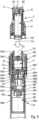
- FIG 4a shows the applicator when the support face N1 is in its most extended position and the pump chamber in its minimum volume state.
- the selector M7 was actuated: the pin M67 of the carriage M6 was driven upwards under the constraint of the cam path M76.
- the M2 motor, its M3 cap and the M4 transmission piston have been moved axially upwards.
- Bellows B has been slightly crushed, so that the maximum useful volume of the pump chamber Cp has decreased slightly.
- the transmission piston M4 has moved the needle holder N, so that the support face N1 is higher than on the figures 1 and 2 : it is substantially or exactly at the same level as the application face AO, while the transmission piston M4 is in the low position.
- the applicator of the figure 4b was turned half a turn.
- the pump chamber Cp is in its minimum volume state and the support face N1 is in the maximum extended position. We see that it is higher than on the figure 4a .
- the fluid product is distributed at the level of the applicator face by pressurizing the air chamber Ca and moving the pusher piston R4, while the NO microneedles will penetrate deeper into the skin due to their advanced position or extent.
- the M7 selector therefore acts on the penetration depth of the NO microneedles.
- the user can adjust this depth themselves according to different parameters, such as the nature of the skin, its suppleness, the nature of the fluid product, the desired result, etc.
- the applicator is always made in two separate separable modules.
- the second module or cartridge C may be similar or identical to that of the first embodiment. And will therefore not be described.
- the motor M2, the oscillating cap M3, the shroud M5, the air outlet valve Vo and the external shell M8 may be similar or identical to those of the first embodiment. Even the M7' selector can be the same, but with a different function.
- the M4 transmission piston of the first embodiment has been replaced by a two-piece M4' transmission piston, namely a lower part M4a and an upper part M4b.
- the carriage M6 of the first embodiment has been replaced by a carriage M6' in two pieces, namely a basket M6a and a valve actuator M6b.
- the lower part M4a of the transmission piston M4' forms the inclined surface M41 which engages with the inclined head of the wobble cap M3.
- the upper part M4b is fixedly mounted on the lower part M4a and forms an inlet conduit M40, a seat M42 for an air inlet valve Vi', a bellows support M43 and transmission means M44 defining ends free from M45 contact, just as in the first embodiment.
- the basket M6a of the carriage M6' forms a housing M62 for the motor M2, its wobbly cap M3, the lower part M4a of the transmission piston M4' and also the lower portion of the upper part M4b.
- the M6b flap actuator is mounted with limited sliding in the M6a basket. It includes an M67 pin engaged in the M76 cam path of the M7' selector, as well as an M64 push finger which extends below the air inlet valve Vi'.
- the valve Vi' comprises a lower heel V6 which is intended to come into contact with the thrust finger M64 to detach the valve Vi' from its seat M42, as will be seen below.
- the basket M6a forms an elongated opening M68 and the valve actuator M6b comprises an M69 pin engaged in the elongated opening M68, so as to be able to move axially over a limited stroke.
- FIG 6a is similar to the figure 4a :
- the selector M7' is in the low position and the motor M2 has turned half a turn, so that the piston M4' is in the maximum high position.
- the pump P was actuated and pressurized air was injected into the air chamber Ca to push the pusher piston R4 and deliver fluid product onto the application face AO.
- the needle holder N remains static, given that the contact ends M45 are out of contact with the needle holder N, even in the high position of the piston M4'.
- the spring abuts on the ferrule M5.
- the applicator is in a configuration in which it only distributes fluid product: the air pump operates normally, while the NO microneedles remain static or inactive. The user can therefore use the applicator without micro-perforation.
- the selector M7' was actuated: the pin M67 of the carriage M6' was driven upwards under the constraint of the cam path M76.
- the M2 motor, its M3 cap and the M4 transmission piston have been moved axially upwards.
- the M45 contact end of the M4 transmission piston is now in contact with the lower end of the return spring S.
- the needle holder N has been moved upwards, so that the support face N1 is now substantially or exactly at the same level as the application face AO, while the transmission piston M4' is in the low position relative to the wobbly cap M3.
- the M64 thrust finger has detached the air inlet valve Vi' from its seat, so that it can no longer fulfill its selective sealing function during overpressure phases in the pump chamber. Cp.
- the movement of the finger thrust M64 relative to the piston M4' is possible, because the valve actuator M6b moves over a small limited axial stroke relative to the basket M6a.
- the applicator of the figure 6b was turned half a turn.
- the cap M3 and the piston M4' have been moved upwards, compressing the spring S and moving the needle holder N.
- the support face N1 is higher than on the figure 6b and that the microneedles NO protrude relative to the application face AO.
- the air pump P did not send air under pressure into the air chamber Ca.
- its inlet valve Vi' is detached from its seat M42, so that the pump chamber Cp cannot be put under pressure.
- the air which enters through the inlet valve Vi' leaves again as soon as the bellows B is crushed.
- the applicator is in a configuration in which it does not distribute fluid product: only the remaining NO microneedles are active. The user can therefore use the applicator without dispensing fluid product.
- the M7' selector acts as a means of permutation allowing you to move from fluid product distribution to micro-perforation, without ever being able to implement both simultaneously.
Landscapes
- Health & Medical Sciences (AREA)
- Engineering & Computer Science (AREA)
- Life Sciences & Earth Sciences (AREA)
- Animal Behavior & Ethology (AREA)
- Anesthesiology (AREA)
- Biomedical Technology (AREA)
- Heart & Thoracic Surgery (AREA)
- Hematology (AREA)
- Dermatology (AREA)
- Medical Informatics (AREA)
- General Health & Medical Sciences (AREA)
- Public Health (AREA)
- Veterinary Medicine (AREA)
- Media Introduction/Drainage Providing Device (AREA)
- Coating Apparatus (AREA)
- Containers And Packaging Bodies Having A Special Means To Remove Contents (AREA)
- Infusion, Injection, And Reservoir Apparatuses (AREA)
Claims (16)
- Applikator mit Mikronadeln zum Auftragen eines Fluidprodukts auf die Haut und zum Eindringen des Fluidprodukts in die Haut, wobei der Applikator eine Längsachse X definiert und umfasst:- eine Applikationsfläche (PO), die mit zumindest einem Fluidproduktauslass (O) versehen ist,- mehrere Mikronadeln (NO),- ein Fluidproduktreservoir (R), das mit dem Fluidproduktauslass (O) verbunden ist,- einen Motor (M2), um die Mikronadeln (NO) in Schwingung zu versetzen und das Fluidprodukt aus dem Fluidproduktreservoir (R) zum Fluidproduktauslass (O) zu leiten,dadurch gekennzeichnet, dass er zwei separate Module (M ; M', C) umfasst, die axial lösbar miteinander verbunden sind, nämlich:- ein erstes Modul (M; M'), das den Motor (M2) und Zubehörteile zum Betreiben des Motors (M2) aufnimmt, und- ein zweites Modul (C), das das Fluidproduktreservoir (R) aufnimmt, die Applikationsfläche (AO) bildet und die Mikronadeln (NO) abstützt.
- Applikator nach Anspruch 1,
wobei das Fluidproduktreservoir (R) ein variables Volumen hat, wobei die Betätigung des Motors (M2) ohne mechanische Kraftübertragung auf das Fluidproduktreservoir (R) einwirkt, um eine Volumenverringerung des Fluidproduktreservoirs (R) zu bewirken, so dass ein Teil seines Inhalts zum Fluidproduktauslass (O) verdrängt wird. - Applikator nach Anspruch 2,
wobei das erste Modul (M; M') eine Luftpumpe (P) umfasst. - Applikator nach Anspruch 3,
wobei das Fluidproduktreservoir (R) eine bewegliche Wand (R4) umfasst, die auch Teil einer Luftkammer (Ca) ist, die mit Druckluft aus der Luftpumpe versorgt wird. - Applikator nach Anspruch 4,
wobei die Luftkammer (Ca) gemeinsam von den beiden abgedichtet angeschlossenen Modulen (M; M', C) gebildet wird. - Applikator nach Anspruch 5,
wobei die Luftpumpe (P) eine Pumpenkammer (Cp) mit einem Lufteinlassventil (Vi; Vi') und einem mit der Luftkammer (Ca) verbundenen Luftauslassventil (Vo) umfasst, wobei die Volumenänderung der Pumpenkammer (Cp) vorteilhafterweise über einen Balg (B) sichergestellt wird. - Applikator nach Anspruch 6,
wobei das Lufteinlassventil (Vi; Vi') durch den Motor (M2) axial hin- und herbewegt wird. - Applikator nach einem der vorhergehenden Ansprüche,
wobei der Motor (M2) eine drehend angetriebene Axialwelle (M21) umfasst, wobei ein System zur Umwandlung von Dreh- in Axialbewegung (M3) an der Drehwelle (M21) angebracht ist. - Applikator nach Anspruch 6,
wobei das erste Modul (M') Abstellmittel (M64) zum Abstellen der Luftpumpe (P) umfasst, um sie daran zu hindern, die Luftkammer (Ca) mit Druckluft zu versorgen, vorteilhafterweise durch Sichern ihres Lufteinlassventils (Vi') in der offenen Position. - Applikator nach einem der vorhergehenden Ansprüche,
wobei das erste Modul (M) Einstellmittel (M6, M7) zum Einstellen der Eindringtiefe der Mikronadeln (NO) umfasst, die vorteilhaft auf die axiale Stellung des Motors (M2) im ersten Modul (M) einwirken. - Applikator nach einem der vorhergehenden Ansprüche,
wobei das erste Modul (M') Zuschalt-/Abschaltmittel (M6', M7') zum Zuschalten/Abschalten der Übertragung der durch den Motor (M2) erzeugten Schwingungen auf die Mikronadeln (NO) umfasst. - Applikator nach Anspruch 9 und 11,
wobei die Luftpumpe (P) abgestellt ist, wenn die Mikronadeln (NO) mit dem Motor (M2) gekoppelt sind. - Applikator nach Anspruch 9 und 11,
wobei die Luftpumpe (P) die Luftkammer (Ca) mit Druckluft versorgt, wenn die Mikronadeln (NO) vom Motor (M2) abgekoppelt sind. - Applikator nach einem der vorhergehenden Ansprüche,
wobei die Applikationsfläche (AO) feststehend ist und die Mikronadeln (NO) an einem Nadelhalter (N) gelagert sind, der vom Motor (M2) hin- und herbewegt wird. - Applikator nach einem der vorhergehenden Ansprüche,
wobei die Mikronadeln (NO) an einem Nadelhalter (N) gelagert sind, der sich um das Fluidproduktreservoir (R) herum erstreckt. - Applikator nach Anspruch 6,
wobei das erste Modul (M; M') einen Kolben (M4; M4') umfasst, der unter der Wirkung des Motors (M2) axial hin- und herbewegt werden kann, wobei dieser Kolben (M4; M4') einen Sitz (M42) für das Lufteinlassventil (Vi; Vi') bildet, sowie eine Halterung (M43) für einen Balg (B) und Übertragungsmittel (M44), um die Mikronadeln (NO) des zweiten Moduls (C) in Schwingung zu versetzen.
Applications Claiming Priority (2)
| Application Number | Priority Date | Filing Date | Title |
|---|---|---|---|
| FR2005784A FR3110855B1 (fr) | 2020-06-02 | 2020-06-02 | Applicateur à micro-aiguilles |
| PCT/FR2021/050988 WO2021245346A1 (fr) | 2020-06-02 | 2021-06-01 | Applicateur a micro-aiguilles |
Publications (2)
| Publication Number | Publication Date |
|---|---|
| EP4157424A1 EP4157424A1 (de) | 2023-04-05 |
| EP4157424B1 true EP4157424B1 (de) | 2024-08-07 |
Family
ID=72885640
Family Applications (1)
| Application Number | Title | Priority Date | Filing Date |
|---|---|---|---|
| EP21734425.8A Active EP4157424B1 (de) | 2020-06-02 | 2021-06-01 | Mikronadelapplikator |
Country Status (8)
| Country | Link |
|---|---|
| US (1) | US20230293870A1 (de) |
| EP (1) | EP4157424B1 (de) |
| JP (1) | JP7685527B2 (de) |
| KR (1) | KR20230017317A (de) |
| CN (1) | CN115697460A (de) |
| ES (1) | ES2993085T3 (de) |
| FR (1) | FR3110855B1 (de) |
| WO (1) | WO2021245346A1 (de) |
Families Citing this family (2)
| Publication number | Priority date | Publication date | Assignee | Title |
|---|---|---|---|---|
| CN115089866B (zh) * | 2022-08-23 | 2022-12-13 | 江西汉氏医学发展有限公司 | 一种外泌体应用于医美的面部种植装置 |
| FR3161860A1 (fr) | 2024-05-03 | 2025-11-07 | Aptar France Sas | Applicateur à micro-aiguilles |
Family Cites Families (13)
| Publication number | Priority date | Publication date | Assignee | Title |
|---|---|---|---|---|
| US4596565A (en) * | 1985-02-14 | 1986-06-24 | Ruderian Max J | Salve applicator |
| US6256533B1 (en) * | 1999-06-09 | 2001-07-03 | The Procter & Gamble Company | Apparatus and method for using an intracutaneous microneedle array |
| US6558361B1 (en) * | 2000-03-09 | 2003-05-06 | Nanopass Ltd. | Systems and methods for the transport of fluids through a biological barrier and production techniques for such systems |
| JP2004121327A (ja) * | 2002-09-30 | 2004-04-22 | Keitouuwai Project:Kk | トリートメントプローブ |
| US8609041B2 (en) * | 2007-08-06 | 2013-12-17 | Samir Mitragotri | Apparatus for solubilizing tissue |
| US9173994B2 (en) * | 2010-08-20 | 2015-11-03 | Purdue Research Foundation | Touch-actuated micropump for transdermal drug delivery and method of use |
| US8776626B2 (en) * | 2010-10-07 | 2014-07-15 | Brian F. Abbott | Pneumatic motor for oscillatory motion |
| JP2017513683A (ja) * | 2014-04-21 | 2017-06-01 | チャン, フランクリン, ジェイ.CHANG, Franklin, J. | 経皮送達の装置と方法 |
| WO2016049732A1 (en) * | 2014-10-03 | 2016-04-07 | Academie Beaute Perform'art Inc. | Apparatus and method for skin treatment |
| CN105268037B (zh) * | 2015-11-16 | 2018-02-13 | 秦皇岛市第一医院 | 一种体表负压施治装置 |
| BR102015028826B1 (pt) * | 2015-11-17 | 2022-07-12 | Augusto Darwin Moreira De Araújo Lima | Aperfeiçoamento introduzido em aplicador automático de injeção |
| KR101980736B1 (ko) * | 2017-06-15 | 2019-05-21 | 정혜영 | 갈바닉 마이크로 니들 피부미용기기 |
| US10773016B2 (en) * | 2017-12-31 | 2020-09-15 | Lydia G You | Implantable micro bubble pump for drug delivery and biomedical applications |
-
2020
- 2020-06-02 FR FR2005784A patent/FR3110855B1/fr active Active
-
2021
- 2021-06-01 US US18/007,654 patent/US20230293870A1/en active Pending
- 2021-06-01 ES ES21734425T patent/ES2993085T3/es active Active
- 2021-06-01 KR KR1020227046333A patent/KR20230017317A/ko active Pending
- 2021-06-01 JP JP2022574507A patent/JP7685527B2/ja active Active
- 2021-06-01 CN CN202180040115.1A patent/CN115697460A/zh active Pending
- 2021-06-01 WO PCT/FR2021/050988 patent/WO2021245346A1/fr not_active Ceased
- 2021-06-01 EP EP21734425.8A patent/EP4157424B1/de active Active
Also Published As
| Publication number | Publication date |
|---|---|
| EP4157424A1 (de) | 2023-04-05 |
| ES2993085T3 (en) | 2024-12-20 |
| US20230293870A1 (en) | 2023-09-21 |
| JP7685527B2 (ja) | 2025-05-29 |
| FR3110855B1 (fr) | 2022-09-02 |
| FR3110855A1 (fr) | 2021-12-03 |
| JP2023529850A (ja) | 2023-07-12 |
| KR20230017317A (ko) | 2023-02-03 |
| WO2021245346A1 (fr) | 2021-12-09 |
| CN115697460A (zh) | 2023-02-03 |
Similar Documents
| Publication | Publication Date | Title |
|---|---|---|
| EP1728494B1 (de) | Massage- und / oder Spendervorrichtung | |
| EP1169938B1 (de) | Vorrichtung zum Aufbewahren und Auftragen eines kosmetischen Produkts | |
| EP2614748B1 (de) | Vorrichtung zum Verpacken und Auftragen | |
| CA2410915C (fr) | Ensemble de conditionnement et d'application d'un produit | |
| EP4157424B1 (de) | Mikronadelapplikator | |
| EP1932500B1 (de) | Hautmassagevorrichtung | |
| FR2936412A1 (fr) | Dispositif de massage,en particulier du cuir chevelu | |
| FR2908019A1 (fr) | Dispositifs et procedes de distribution sous pression de produits dans des distributeurs cosmetiques | |
| FR2810858A1 (fr) | Embout de distribution comportant deux parties assemblees et un revetement de flocage | |
| FR2908753A1 (fr) | Dispositif pour delivrer automatiquement des doses successives de produit | |
| EP1626813A2 (de) | Ausgabevorrichtung für fluide produkte und verfahren zur montage einer solchen ausgabevorrichtung | |
| EP1728495B1 (de) | Massage- und / oder Spendervorrichtung | |
| EP4291281B1 (de) | Mikronadelapplikator | |
| FR2892276A1 (fr) | Distributeur applicateur d'un produit, typiquement un produit cosmetique | |
| EP3694656A1 (de) | Flüssigproduktspender | |
| FR2951918A1 (fr) | Applicateur comportant une liaison permettant d'incliner la surface d'application | |
| EP4157425B1 (de) | Mikronadelapplikator | |
| FR3142673A1 (fr) | Module de distribution pour un appareil destiné à l’application d’un produit colorant et appareil utilisant un tel module | |
| FR2984287A1 (fr) | Dispositif de conditionnement et de distribution d'un melange de produits | |
| EP0922405B1 (de) | Spender für kosmetische Produkte zum Schminken | |
| FR2889692A1 (fr) | Dispositif de distribution d'un produit fluide | |
| EP1652447A1 (de) | Epilationsgerät mit einer Vorrichtung zur Hautbehandlung | |
| FR3104392A1 (fr) | Recharge de produit cosmétique, destinée à être montée de manière amovible dans une frette d’habillage, ensemble de chargement, nécessaire, dispositif et procédé de montage associé | |
| FR3021510A1 (fr) | Applicateur de produit cosmetique a pointe feutre | |
| FR2889691A1 (fr) | Dispositif de distribution d'un produit fluide sous forme de goutte |
Legal Events
| Date | Code | Title | Description |
|---|---|---|---|
| STAA | Information on the status of an ep patent application or granted ep patent |
Free format text: STATUS: UNKNOWN |
|
| STAA | Information on the status of an ep patent application or granted ep patent |
Free format text: STATUS: THE INTERNATIONAL PUBLICATION HAS BEEN MADE |
|
| PUAI | Public reference made under article 153(3) epc to a published international application that has entered the european phase |
Free format text: ORIGINAL CODE: 0009012 |
|
| STAA | Information on the status of an ep patent application or granted ep patent |
Free format text: STATUS: REQUEST FOR EXAMINATION WAS MADE |
|
| 17P | Request for examination filed |
Effective date: 20221228 |
|
| AK | Designated contracting states |
Kind code of ref document: A1 Designated state(s): AL AT BE BG CH CY CZ DE DK EE ES FI FR GB GR HR HU IE IS IT LI LT LU LV MC MK MT NL NO PL PT RO RS SE SI SK SM TR |
|
| DAV | Request for validation of the european patent (deleted) | ||
| DAX | Request for extension of the european patent (deleted) | ||
| GRAP | Despatch of communication of intention to grant a patent |
Free format text: ORIGINAL CODE: EPIDOSNIGR1 |
|
| STAA | Information on the status of an ep patent application or granted ep patent |
Free format text: STATUS: GRANT OF PATENT IS INTENDED |
|
| INTG | Intention to grant announced |
Effective date: 20240208 |
|
| P01 | Opt-out of the competence of the unified patent court (upc) registered |
Effective date: 20240318 |
|
| GRAS | Grant fee paid |
Free format text: ORIGINAL CODE: EPIDOSNIGR3 |
|
| GRAA | (expected) grant |
Free format text: ORIGINAL CODE: 0009210 |
|
| STAA | Information on the status of an ep patent application or granted ep patent |
Free format text: STATUS: THE PATENT HAS BEEN GRANTED |
|
| AK | Designated contracting states |
Kind code of ref document: B1 Designated state(s): AL AT BE BG CH CY CZ DE DK EE ES FI FR GB GR HR HU IE IS IT LI LT LU LV MC MK MT NL NO PL PT RO RS SE SI SK SM TR |
|
| REG | Reference to a national code |
Ref country code: GB Ref legal event code: FG4D Free format text: NOT ENGLISH |
|
| REG | Reference to a national code |
Ref country code: CH Ref legal event code: EP |
|
| REG | Reference to a national code |
Ref country code: IE Ref legal event code: FG4D Free format text: LANGUAGE OF EP DOCUMENT: FRENCH |
|
| REG | Reference to a national code |
Ref country code: DE Ref legal event code: R096 Ref document number: 602021016868 Country of ref document: DE |
|
| REG | Reference to a national code |
Ref country code: LT Ref legal event code: MG9D |
|
| REG | Reference to a national code |
Ref country code: NL Ref legal event code: MP Effective date: 20240807 |
|
| REG | Reference to a national code |
Ref country code: ES Ref legal event code: FG2A Ref document number: 2993085 Country of ref document: ES Kind code of ref document: T3 Effective date: 20241220 |
|
| PG25 | Lapsed in a contracting state [announced via postgrant information from national office to epo] |
Ref country code: NO Free format text: LAPSE BECAUSE OF FAILURE TO SUBMIT A TRANSLATION OF THE DESCRIPTION OR TO PAY THE FEE WITHIN THE PRESCRIBED TIME-LIMIT Effective date: 20241107 |
|
| REG | Reference to a national code |
Ref country code: AT Ref legal event code: MK05 Ref document number: 1710278 Country of ref document: AT Kind code of ref document: T Effective date: 20240807 |
|
| PG25 | Lapsed in a contracting state [announced via postgrant information from national office to epo] |
Ref country code: GR Free format text: LAPSE BECAUSE OF FAILURE TO SUBMIT A TRANSLATION OF THE DESCRIPTION OR TO PAY THE FEE WITHIN THE PRESCRIBED TIME-LIMIT Effective date: 20241108 Ref country code: NL Free format text: LAPSE BECAUSE OF FAILURE TO SUBMIT A TRANSLATION OF THE DESCRIPTION OR TO PAY THE FEE WITHIN THE PRESCRIBED TIME-LIMIT Effective date: 20240807 Ref country code: FI Free format text: LAPSE BECAUSE OF FAILURE TO SUBMIT A TRANSLATION OF THE DESCRIPTION OR TO PAY THE FEE WITHIN THE PRESCRIBED TIME-LIMIT Effective date: 20240807 Ref country code: PT Free format text: LAPSE BECAUSE OF FAILURE TO SUBMIT A TRANSLATION OF THE DESCRIPTION OR TO PAY THE FEE WITHIN THE PRESCRIBED TIME-LIMIT Effective date: 20241209 Ref country code: PL Free format text: LAPSE BECAUSE OF FAILURE TO SUBMIT A TRANSLATION OF THE DESCRIPTION OR TO PAY THE FEE WITHIN THE PRESCRIBED TIME-LIMIT Effective date: 20240807 |
|
| PG25 | Lapsed in a contracting state [announced via postgrant information from national office to epo] |
Ref country code: BG Free format text: LAPSE BECAUSE OF FAILURE TO SUBMIT A TRANSLATION OF THE DESCRIPTION OR TO PAY THE FEE WITHIN THE PRESCRIBED TIME-LIMIT Effective date: 20240807 |
|
| PG25 | Lapsed in a contracting state [announced via postgrant information from national office to epo] |
Ref country code: LV Free format text: LAPSE BECAUSE OF FAILURE TO SUBMIT A TRANSLATION OF THE DESCRIPTION OR TO PAY THE FEE WITHIN THE PRESCRIBED TIME-LIMIT Effective date: 20240807 |
|
| PG25 | Lapsed in a contracting state [announced via postgrant information from national office to epo] |
Ref country code: IS Free format text: LAPSE BECAUSE OF FAILURE TO SUBMIT A TRANSLATION OF THE DESCRIPTION OR TO PAY THE FEE WITHIN THE PRESCRIBED TIME-LIMIT Effective date: 20241207 Ref country code: AT Free format text: LAPSE BECAUSE OF FAILURE TO SUBMIT A TRANSLATION OF THE DESCRIPTION OR TO PAY THE FEE WITHIN THE PRESCRIBED TIME-LIMIT Effective date: 20240807 |
|
| PG25 | Lapsed in a contracting state [announced via postgrant information from national office to epo] |
Ref country code: HR Free format text: LAPSE BECAUSE OF FAILURE TO SUBMIT A TRANSLATION OF THE DESCRIPTION OR TO PAY THE FEE WITHIN THE PRESCRIBED TIME-LIMIT Effective date: 20240807 |
|
| PG25 | Lapsed in a contracting state [announced via postgrant information from national office to epo] |
Ref country code: RS Free format text: LAPSE BECAUSE OF FAILURE TO SUBMIT A TRANSLATION OF THE DESCRIPTION OR TO PAY THE FEE WITHIN THE PRESCRIBED TIME-LIMIT Effective date: 20241107 |
|
| PG25 | Lapsed in a contracting state [announced via postgrant information from national office to epo] |
Ref country code: RS Free format text: LAPSE BECAUSE OF FAILURE TO SUBMIT A TRANSLATION OF THE DESCRIPTION OR TO PAY THE FEE WITHIN THE PRESCRIBED TIME-LIMIT Effective date: 20241107 Ref country code: PT Free format text: LAPSE BECAUSE OF FAILURE TO SUBMIT A TRANSLATION OF THE DESCRIPTION OR TO PAY THE FEE WITHIN THE PRESCRIBED TIME-LIMIT Effective date: 20241209 Ref country code: PL Free format text: LAPSE BECAUSE OF FAILURE TO SUBMIT A TRANSLATION OF THE DESCRIPTION OR TO PAY THE FEE WITHIN THE PRESCRIBED TIME-LIMIT Effective date: 20240807 Ref country code: NO Free format text: LAPSE BECAUSE OF FAILURE TO SUBMIT A TRANSLATION OF THE DESCRIPTION OR TO PAY THE FEE WITHIN THE PRESCRIBED TIME-LIMIT Effective date: 20241107 Ref country code: NL Free format text: LAPSE BECAUSE OF FAILURE TO SUBMIT A TRANSLATION OF THE DESCRIPTION OR TO PAY THE FEE WITHIN THE PRESCRIBED TIME-LIMIT Effective date: 20240807 Ref country code: LV Free format text: LAPSE BECAUSE OF FAILURE TO SUBMIT A TRANSLATION OF THE DESCRIPTION OR TO PAY THE FEE WITHIN THE PRESCRIBED TIME-LIMIT Effective date: 20240807 Ref country code: IS Free format text: LAPSE BECAUSE OF FAILURE TO SUBMIT A TRANSLATION OF THE DESCRIPTION OR TO PAY THE FEE WITHIN THE PRESCRIBED TIME-LIMIT Effective date: 20241207 Ref country code: HR Free format text: LAPSE BECAUSE OF FAILURE TO SUBMIT A TRANSLATION OF THE DESCRIPTION OR TO PAY THE FEE WITHIN THE PRESCRIBED TIME-LIMIT Effective date: 20240807 Ref country code: GR Free format text: LAPSE BECAUSE OF FAILURE TO SUBMIT A TRANSLATION OF THE DESCRIPTION OR TO PAY THE FEE WITHIN THE PRESCRIBED TIME-LIMIT Effective date: 20241108 Ref country code: FI Free format text: LAPSE BECAUSE OF FAILURE TO SUBMIT A TRANSLATION OF THE DESCRIPTION OR TO PAY THE FEE WITHIN THE PRESCRIBED TIME-LIMIT Effective date: 20240807 Ref country code: BG Free format text: LAPSE BECAUSE OF FAILURE TO SUBMIT A TRANSLATION OF THE DESCRIPTION OR TO PAY THE FEE WITHIN THE PRESCRIBED TIME-LIMIT Effective date: 20240807 Ref country code: AT Free format text: LAPSE BECAUSE OF FAILURE TO SUBMIT A TRANSLATION OF THE DESCRIPTION OR TO PAY THE FEE WITHIN THE PRESCRIBED TIME-LIMIT Effective date: 20240807 |
|
| PG25 | Lapsed in a contracting state [announced via postgrant information from national office to epo] |
Ref country code: DK Free format text: LAPSE BECAUSE OF FAILURE TO SUBMIT A TRANSLATION OF THE DESCRIPTION OR TO PAY THE FEE WITHIN THE PRESCRIBED TIME-LIMIT Effective date: 20240807 Ref country code: SM Free format text: LAPSE BECAUSE OF FAILURE TO SUBMIT A TRANSLATION OF THE DESCRIPTION OR TO PAY THE FEE WITHIN THE PRESCRIBED TIME-LIMIT Effective date: 20240807 |
|
| PG25 | Lapsed in a contracting state [announced via postgrant information from national office to epo] |
Ref country code: EE Free format text: LAPSE BECAUSE OF FAILURE TO SUBMIT A TRANSLATION OF THE DESCRIPTION OR TO PAY THE FEE WITHIN THE PRESCRIBED TIME-LIMIT Effective date: 20240807 |
|
| PG25 | Lapsed in a contracting state [announced via postgrant information from national office to epo] |
Ref country code: CZ Free format text: LAPSE BECAUSE OF FAILURE TO SUBMIT A TRANSLATION OF THE DESCRIPTION OR TO PAY THE FEE WITHIN THE PRESCRIBED TIME-LIMIT Effective date: 20240807 |
|
| PG25 | Lapsed in a contracting state [announced via postgrant information from national office to epo] |
Ref country code: SK Free format text: LAPSE BECAUSE OF FAILURE TO SUBMIT A TRANSLATION OF THE DESCRIPTION OR TO PAY THE FEE WITHIN THE PRESCRIBED TIME-LIMIT Effective date: 20240807 |
|
| REG | Reference to a national code |
Ref country code: DE Ref legal event code: R097 Ref document number: 602021016868 Country of ref document: DE |
|
| PLBE | No opposition filed within time limit |
Free format text: ORIGINAL CODE: 0009261 |
|
| STAA | Information on the status of an ep patent application or granted ep patent |
Free format text: STATUS: NO OPPOSITION FILED WITHIN TIME LIMIT |
|
| PGFP | Annual fee paid to national office [announced via postgrant information from national office to epo] |
Ref country code: DE Payment date: 20250617 Year of fee payment: 5 |
|
| 26N | No opposition filed |
Effective date: 20250508 |
|
| PGFP | Annual fee paid to national office [announced via postgrant information from national office to epo] |
Ref country code: FR Payment date: 20250627 Year of fee payment: 5 |
|
| PG25 | Lapsed in a contracting state [announced via postgrant information from national office to epo] |
Ref country code: SE Free format text: LAPSE BECAUSE OF FAILURE TO SUBMIT A TRANSLATION OF THE DESCRIPTION OR TO PAY THE FEE WITHIN THE PRESCRIBED TIME-LIMIT Effective date: 20240807 |
|
| PGFP | Annual fee paid to national office [announced via postgrant information from national office to epo] |
Ref country code: ES Payment date: 20250710 Year of fee payment: 5 |
|
| REG | Reference to a national code |
Ref country code: CH Ref legal event code: H13 Free format text: ST27 STATUS EVENT CODE: U-0-0-H10-H13 (AS PROVIDED BY THE NATIONAL OFFICE) Effective date: 20260127 |
|
| PG25 | Lapsed in a contracting state [announced via postgrant information from national office to epo] |
Ref country code: MC Free format text: LAPSE BECAUSE OF FAILURE TO SUBMIT A TRANSLATION OF THE DESCRIPTION OR TO PAY THE FEE WITHIN THE PRESCRIBED TIME-LIMIT Effective date: 20240807 |
|
| PG25 | Lapsed in a contracting state [announced via postgrant information from national office to epo] |
Ref country code: LU Free format text: LAPSE BECAUSE OF NON-PAYMENT OF DUE FEES Effective date: 20250601 |
|
| GBPC | Gb: european patent ceased through non-payment of renewal fee |
Effective date: 20250601 |
|
| REG | Reference to a national code |
Ref country code: BE Ref legal event code: MM Effective date: 20250630 |
|
| PG25 | Lapsed in a contracting state [announced via postgrant information from national office to epo] |
Ref country code: GB Free format text: LAPSE BECAUSE OF NON-PAYMENT OF DUE FEES Effective date: 20250601 |
|
| PG25 | Lapsed in a contracting state [announced via postgrant information from national office to epo] |
Ref country code: IE Free format text: LAPSE BECAUSE OF NON-PAYMENT OF DUE FEES Effective date: 20250601 |
|
| PG25 | Lapsed in a contracting state [announced via postgrant information from national office to epo] |
Ref country code: BE Free format text: LAPSE BECAUSE OF NON-PAYMENT OF DUE FEES Effective date: 20250630 Ref country code: RO Free format text: LAPSE BECAUSE OF FAILURE TO SUBMIT A TRANSLATION OF THE DESCRIPTION OR TO PAY THE FEE WITHIN THE PRESCRIBED TIME-LIMIT Effective date: 20240807 Ref country code: IT Free format text: LAPSE BECAUSE OF NON-PAYMENT OF DUE FEES Effective date: 20250601 |
|
| PG25 | Lapsed in a contracting state [announced via postgrant information from national office to epo] |
Ref country code: CH Free format text: LAPSE BECAUSE OF NON-PAYMENT OF DUE FEES Effective date: 20250630 |