EP4156865A1 - Beleuchtungssystem, das mehrere lichtquellen aufweist, und steuerverfahren dafür - Google Patents
Beleuchtungssystem, das mehrere lichtquellen aufweist, und steuerverfahren dafür Download PDFInfo
- Publication number
- EP4156865A1 EP4156865A1 EP22158787.6A EP22158787A EP4156865A1 EP 4156865 A1 EP4156865 A1 EP 4156865A1 EP 22158787 A EP22158787 A EP 22158787A EP 4156865 A1 EP4156865 A1 EP 4156865A1
- Authority
- EP
- European Patent Office
- Prior art keywords
- light source
- module
- control module
- light
- malfunctions
- Prior art date
- Legal status (The legal status is an assumption and is not a legal conclusion. Google has not performed a legal analysis and makes no representation as to the accuracy of the status listed.)
- Granted
Links
Images


Classifications
-
- H—ELECTRICITY
- H05—ELECTRIC TECHNIQUES NOT OTHERWISE PROVIDED FOR
- H05B—ELECTRIC HEATING; ELECTRIC LIGHT SOURCES NOT OTHERWISE PROVIDED FOR; CIRCUIT ARRANGEMENTS FOR ELECTRIC LIGHT SOURCES, IN GENERAL
- H05B45/00—Circuit arrangements for operating light-emitting diodes [LED]
- H05B45/50—Circuit arrangements for operating light-emitting diodes [LED] responsive to malfunctions or undesirable behaviour of LEDs; responsive to LED life; Protective circuits
-
- H—ELECTRICITY
- H05—ELECTRIC TECHNIQUES NOT OTHERWISE PROVIDED FOR
- H05B—ELECTRIC HEATING; ELECTRIC LIGHT SOURCES NOT OTHERWISE PROVIDED FOR; CIRCUIT ARRANGEMENTS FOR ELECTRIC LIGHT SOURCES, IN GENERAL
- H05B47/00—Circuit arrangements for operating light sources in general, i.e. where the type of light source is not relevant
- H05B47/20—Responsive to malfunctions or to light source life; for protection
-
- H—ELECTRICITY
- H05—ELECTRIC TECHNIQUES NOT OTHERWISE PROVIDED FOR
- H05B—ELECTRIC HEATING; ELECTRIC LIGHT SOURCES NOT OTHERWISE PROVIDED FOR; CIRCUIT ARRANGEMENTS FOR ELECTRIC LIGHT SOURCES, IN GENERAL
- H05B47/00—Circuit arrangements for operating light sources in general, i.e. where the type of light source is not relevant
- H05B47/10—Controlling the light source
- H05B47/105—Controlling the light source in response to determined parameters
-
- H—ELECTRICITY
- H05—ELECTRIC TECHNIQUES NOT OTHERWISE PROVIDED FOR
- H05B—ELECTRIC HEATING; ELECTRIC LIGHT SOURCES NOT OTHERWISE PROVIDED FOR; CIRCUIT ARRANGEMENTS FOR ELECTRIC LIGHT SOURCES, IN GENERAL
- H05B47/00—Circuit arrangements for operating light sources in general, i.e. where the type of light source is not relevant
- H05B47/10—Controlling the light source
- H05B47/155—Coordinated control of two or more light sources
-
- H—ELECTRICITY
- H05—ELECTRIC TECHNIQUES NOT OTHERWISE PROVIDED FOR
- H05B—ELECTRIC HEATING; ELECTRIC LIGHT SOURCES NOT OTHERWISE PROVIDED FOR; CIRCUIT ARRANGEMENTS FOR ELECTRIC LIGHT SOURCES, IN GENERAL
- H05B47/00—Circuit arrangements for operating light sources in general, i.e. where the type of light source is not relevant
- H05B47/10—Controlling the light source
- H05B47/175—Controlling the light source by remote control
-
- H—ELECTRICITY
- H05—ELECTRIC TECHNIQUES NOT OTHERWISE PROVIDED FOR
- H05B—ELECTRIC HEATING; ELECTRIC LIGHT SOURCES NOT OTHERWISE PROVIDED FOR; CIRCUIT ARRANGEMENTS FOR ELECTRIC LIGHT SOURCES, IN GENERAL
- H05B47/00—Circuit arrangements for operating light sources in general, i.e. where the type of light source is not relevant
- H05B47/20—Responsive to malfunctions or to light source life; for protection
- H05B47/29—Circuits providing for substitution of the light source in case of its failure
-
- H—ELECTRICITY
- H05—ELECTRIC TECHNIQUES NOT OTHERWISE PROVIDED FOR
- H05B—ELECTRIC HEATING; ELECTRIC LIGHT SOURCES NOT OTHERWISE PROVIDED FOR; CIRCUIT ARRANGEMENTS FOR ELECTRIC LIGHT SOURCES, IN GENERAL
- H05B47/00—Circuit arrangements for operating light sources in general, i.e. where the type of light source is not relevant
- H05B47/10—Controlling the light source
- H05B47/105—Controlling the light source in response to determined parameters
- H05B47/14—Controlling the light source in response to determined parameters by determining electrical parameters of the light source
-
- Y—GENERAL TAGGING OF NEW TECHNOLOGICAL DEVELOPMENTS; GENERAL TAGGING OF CROSS-SECTIONAL TECHNOLOGIES SPANNING OVER SEVERAL SECTIONS OF THE IPC; TECHNICAL SUBJECTS COVERED BY FORMER USPC CROSS-REFERENCE ART COLLECTIONS [XRACs] AND DIGESTS
- Y02—TECHNOLOGIES OR APPLICATIONS FOR MITIGATION OR ADAPTATION AGAINST CLIMATE CHANGE
- Y02B—CLIMATE CHANGE MITIGATION TECHNOLOGIES RELATED TO BUILDINGS, e.g. HOUSING, HOUSE APPLIANCES OR RELATED END-USER APPLICATIONS
- Y02B20/00—Energy efficient lighting technologies, e.g. halogen lamps or gas discharge lamps
- Y02B20/40—Control techniques providing energy savings, e.g. smart controller or presence detection
Definitions
- the present invention relates to a lighting system, in particular to a lighting system having multiple light sources.
- the present invention further relates to the control method of the lighting system.
- LED lighting devices have many advantages, such as energy-saving, small size, high efficiency, etc. Thus, LED lighting devices have become the development trend in the future. However, currently available lighting devices have no a proper control mechanism. Therefore, once any one of the lighting devices of a lighting system malfunctions, the user should immediately replace this light device, which is very inconvenient in use.
- the present invention is related to a lighting system having multiple light sources.
- the lighting system includes a first light source and a second light source.
- the first light source includes a first control module, a second memory module, a first lighting-emitting module and a first detection module.
- the second light source includes a second control module.
- the first control module and the second control module turn off the first light source and the second light source respectively.
- the first control module reads a data of the first memory module of the first light source in order to determine whether the first light source malfunctions, and turns on the first light-emitting module when the first control module determines that the first light source does not malfunction.
- the first detection module keeps detecting whether the first light source malfunctions after the first light-emitting module is turned on.
- the second light source further includes a second light-emitting module.
- the first control module determines that the first light source malfunctions, the first control module transmits a turn-on signal to the second control module, such that the second control module turns on the second light-emitting module.
- the second light source further includes a second memory module and a second light-emitting module.
- the first detection module detects that the first light source malfunctions
- the first control module turns off the first light source, and transmits a first fault signal to the second control module and saves the first fault signal in the first memory module.
- the second control module receives the first fault signal
- the second control module turns on the second light-emitting module and saves the first fault signal in the second memory module.
- the second light source further includes a second detection module.
- the second detection module keeps detecting whether the second light source malfunctions after the second light-emitting module is turned on.
- the second control module turns off the second light source and saves a second fault signal in the second memory.
- the second light source further includes a second light-emitting module.
- the second control module detects that the first light source malfunctions and fails to receives a first fault signal transmitted by the first control module within a predetermined time period, the second control module turns on the second light-emitting module.
- the present invention is further related to a control method for a lighting system having multiple light sources.
- the control method includes the following steps: turning off a first light source and a second light source by the first control module of a first light source and the second control module of a second light source respectively when the first light source and the second light source are electrically connected to a power source; reading the data of the first memory module of the first light source by the first control module in order to determine whether the first light source malfunctions; turning on the first light-emitting module of the first light source by the first control module when the first control module determines that the first light source does not malfunction; and keeping detecting whether the first light source malfunctions by the first detection module of the first light source.
- the step of reading the data of the first memory module of the first light source by the first control module in order to determine whether the first light source malfunctions further includes the following step: transmitting a turn-on signal to the second control module by the first control module and turning on the second light-emitting module of the second light source by the second control module when the first control module determines that the first light source malfunctions.
- control method further includes the following steps: turning off the first light source, transmitting a first fault signal to the second control module and saving the first fault signal in the first memory module by the first control module when the first detection module detects that the first light source malfunctions; and turning on the second light-emitting module of the second light source and saving the first fault signal in the second memory module of the second light source by the second control module when the second control module receives the first fault signal.
- control method further includes the following step: keeping detecting whether the second light source malfunctions by the second detection module of the second light source; and turning off the second light source and saving a second fault signal in the second memory module by the second control module when the second detection module detects that the second light source malfunctions.
- control method further includes the following step: turning on the second light-emitting module of the second light source by the second control module when the second control module detects that the first light source malfunctions and fails to receive a first fault signal transmitted by the first control module within a predetermined time period.
- the lighting system having multiple light sources and the control method thereof in accordance with the present invention may include the following advantages:
- the lighting system having multiple light sources includes a first light source and a second light source; the first light source can serve as a main light source and the second light source can serve as a spare light source.
- the lighting system having multiple light sources can turn on the second light source when the first light source malfunctions, such that the lighting system can operate normally even if the first light source malfunctions, which is more convenient in use.
- the first light source and the second light source of the lighting system having multiple light sources can communicate with each other, and the lighting system can further provide a special switching mechanism and a special detection mechanism. Therefore, the lighting system can precisely detect whether the first light source malfunctions and turn on the second light source on time. Accordingly, the lighting system can achieve great reliability.
- the lighting system having multiple light sources can directly turn on the second light source via a special activation mechanism when the first light source malfunctions and cannot transmit signals.
- the lighting system can make sure that the second light source can be normally turned on when the first light source malfunctions, which can further enhance the reliability of the lighting system.
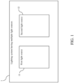
- FIG. 1 is a block diagram of a lighting system having multiple light sources in accordance with one embodiment of the present invention.
- FIG. 2 is a block diagram of a first light source of the lighting system having multiple light sources in accordance with one embodiment of the present invention.
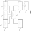
- FIG. 3 is a block diagram of a second light source of the lighting system having multiple light sources in accordance with one embodiment of the present invention.
- the lighting system 1 having multiple light sources includes a first light source 11 and a second light source 12.
- the first light source 11 may serve as the main light source and the second light source 12 may serve as a spare light source.
- the lighting system 1 is a lighting device having two light sources.
- the first light source 11 may be a lighting device and the second light source 12 may be another lighting device.
- the first light source 11 includes a first control module 111, a first memory module 112, a first detection module 113, a first driver module 114, a first light-emitting module 115, a first wireless communication module 116 and a first microwave module 117.
- the first control module 111 is connected to the first memory module 112, the first detection module 113, the first driver module 114, the first wireless communication module 116 and the first microwave module 117.
- the first driver module 114 is connected to the first light-emitting module 115.
- the first control module 111 may be a microcontroller (MCU), a central processing unit (CPU) or other similar components.
- the first memory module 112 may be an electrically-erasable programmable read-only memory (EEPROM), a flash memory or other similar components.
- the first detection module 113 may be various sensors/detectors capable of detecting voltage and/or current signals.
- the first wireless communication module 116 may be a Bluetooth communication module, a ZigBee communication module or other similar components.
- the first light-emitting module 115 may be a light-emitting diode (LED), a gas discharge lamp or other similar components.
- the first driver module 114 may be a driver matching the first light-emitting module 115 and able to drive the first driver module 114.
- the first microwave module 117 may be a microwave radar sensor or other similar components. The first microwave module 117 can detect whether an object enters the detecting range thereof, such that the first control module 111 can perform the corresponding operation.
- the circuit structure of the second light source 12 may be the same with that of the first light source 11.
- the second light source 12 includes a second control module 121, a second memory module 122, a second detection module 123, a second driver module 124, a second light-emitting module 125, a second wireless communication module 126 and a second microwave module 127.
- the second control module 121 is connected to the second memory module 122, the second detection module 123, the second driver module 124, the second wireless communication module 126 and the second microwave module 127.
- the functions of the above elements of the second light source 12 are the same with those of the elements of the first light source 11, so will not be described herein.
- the first control module 111 and the second control module 121 can communicate with each other via the first wireless communication module 116 and the second wireless communication module 126.
- the first light source 11 is connected to the main mechanical switch; besides, the first light source 11 is also connected to the second light source 12.
- the main mechanical switch is connected to a power source (power grid).
- the first control module 111 turns off the electronic switch configured to control the first light-emitting module 115 and transmits a control signal to the second control module 121.
- the second control module 121 turns off the electronic switch configured to control the second light-emitting module 125.
- the first control module 111 reads the data of the first memory module 112 in order to determine whether the first light source 11 malfunctions. When the first control module 111 determines that the first light source 11 does not malfunction, the first control module 111 turns on the first light-emitting module 115 via the first driver module 114 and transmits a control signal to the second control module 121. In the meanwhile, the second control module 121 turns off the auxiliary mechanical switch thereof connected to the power source so as to completely turn off the second light source 12.
- the first detection module 113 keeps detecting whether the first light source 11 malfunctions.
- the first detection module 113 can sample the voltage/current signals of the first light source 11 in order to detect whether any one of the faults of overheating, flickering, short circuit and open circuit in the first light source 11 occurs.
- the first control module 111 reads the data of the first memory module 112 and finds out the malfunctioning record, the first control module 111 transmits a turn-on signal to the second control module 121. Then, the second control module 121 turns on the second light-emitting module 125 (the auxiliary mechanical switch and the electronic switch configured to control the second light-emitting module 125 are simultaneously turned on).
- the lighting system 1 having multiple light sources can still operate normally.
- the first control module 111 turns off the first light source 11 (the electronic switch, configured to control the first light-emitting module 115, is turned off). Meanwhile, the first detection module 113 transmits a first fault signal to the second control module 121 and saves the first fault signal in the first memory module 112. Afterward, when the second control module 121 receives the first fault signal, the second control module 121 turns on the second light-emitting module 125 (the auxiliary mechanical switch and the electronic switch, configured to control the second light-emitting module 125, are turned on at the same time) and saves the first fault signal in the second memory module 122, such that the lighting system 1 having multiple light sources can still operate normally.
- the second control module 121 turns on the second light-emitting module 125 (the auxiliary mechanical switch and the electronic switch, configured to control the second light-emitting module 125, are turned on at the same time) and saves the first fault signal in the second memory module 122, such that the lighting system 1 having multiple light sources can still operate normally.
- the second detection module 123 when the second light source 12 is turned on, the second detection module 123 also keeps detecting whether the second light source 12 malfunctions.
- the second detection module 123 can sample the voltage/current signals of the second light source 12 in order to detect whether any one of the faults of overheating, flickering, short circuit and open circuit in the second light source 12 occurs.
- the second control module 121 turns off the second light source 12 (the electronic switch, configured to control the second light-emitting module 125, is turned off, or the above electronic switch and the auxiliary mechanical switch are turned off at the same time) and saves a second fault signal in the second memory module 122.
- the first detection module 113 detects that the first light source 11 malfunctions, the first light source 11 may be seriously damaged and cannot transmits any signals.
- the second control module 121 detects that the first light source 11 malfunctions and fails to receive the first fault signal transmitted by the first control module 111, the second control module 121 can directly turn on the second light-emitting module 125 of the second light source 12 (when the first detection module 113 detects that the first light source 11 malfunctions, the first control module 111 can turn on the auxiliary mechanical switch first via the communication function), such that the lighting system 1 having multiple light sources can still operate normally.
- the lighting system 1 having multiple light sources has the fist light source 11 and the second light source 12 to serve as the main light source and the spare light source respectively, so the lighting system 1 can turn on the second light source 12 when the first light source 11 malfunctions. Therefore, the lighting system 1 can be always in normal operation status, which is more convenient in use.
- the first light source 11 and the second light source 12 of the lighting system 1 can communicate with each other, and the lighting system 1 can further provide a special switching mechanism and a special error detection mechanism.
- the lighting system 1 can precisely detect that the first light source 11 malfunctions and turn on the second light source 12 on time, which can enhance the reliability of the lighting system 1.
- the lighting system 1 having multiple light sources can directly turn on the second light source 12 via a special activation mechanism when the first light source 11 is seriously damaged and cannot transmit any signals. Therefore, the lighting system 1 can make sure that the second light source 12 can be normally turned on when the first light source 11 malfunctions, which can further enhance the reliability of the lighting system 1.
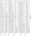
- FIG. 4 is a flow chart of a control method for the lighting system having multiple light sources in accordance with one embodiment of the present invention.
- the control method of the lighting system having multiple light sources in accordance with the embodiment of the present invention includes the following steps:
- Step S41 turning off a first light source and a second light source by the first control module of a first light source and the second control module of a second light source respectively when the first light source and the second light source are electrically connected to a power source.
- Step S42 reading the data of the first memory module of the first light source by the first control module in order to determine whether the first light source malfunctions.
- Step S43 turning on the first light-emitting module of the first light source by the first control module when the first control module determines that the first light source does not malfunction, or transmitting a turn-on signal to the second control module by the first control module and turning on the second light-emitting module of the second light source by the second control module when the first control module determines that the first light source malfunctions.
- Step S44 keeping detecting whether the first light source malfunctions by the first detection module of the first light source.
- Step S45 turning off the first light source, transmitting a first fault signal to the second control module and saving the first fault signal in the first memory module by the first control module when the first detection module detects that the first light source malfunctions, and turning on the second light-emitting module of the second light source and saving the first fault signal in the second memory module of the second light source by the second control module when the second control module receives the first fault signal.
- Step S46 turning off the second light source and saving a second fault signal in the second memory module by the second control module when the second detection module detects that the second light source malfunctions.
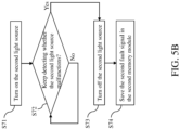
- FIG. 5A and FIG. 5B are a first flow chart and a second flow chart of a control method for a lighting system having multiple light sources in accordance with another embodiment of the present invention.
- This embodiment illustrates each of the steps of the control method, as follows:
- Step S51 connect the first light source and the second light source to the power source; then, the process proceeds to Step S52.
- Step S52 turn off the first light source and the second light source; then, the process proceeds to Step S53.
- the first control module of the first light source turns off the electronic switch configured to control the first light-emitting module thereof and transmits the control signal to the second control module of the second light source.
- Step S53 read the data of the first memory module; then, the process proceeds to Step S54.
- the first control module reads the data of the first memory module of the first light source.
- Step S54 determine whether the first light source malfunctions? If it does, the process proceeds to Step S71; if it does not, the process proceeds to Step S541. In this step, the first control module determines whether the first light source malfunctions according to the data of the first memory module.
- Step S541 turn on the first light source; then, the process proceeds to Step S542.
- the first control module turns on the first light-emitting module via the first driver module of the first light source.
- Step S542 turn off the second light source; then, the process proceeds to Step S543.
- the first control module transmits the control signal to the second control module and then the second control module turns off the auxiliary mechanical switch thereof connected to the power source so as to completely turn off the second light source.
- Step S543 keep detecting whether the first light source malfunctions? If it does, the process proceeds to Step S61; if it does not, the step is continuously repeated.
- the first detection module can sample the voltage/current signals of the first light source by the predetermined frequency in order to detect whether the first light source malfunctions.
- Step S61 turn off the first light source; then, the process proceeds to Step S611 or Strep S62.
- the first control module turns off the first light source (the electronic switch, configured to control the first light-emitting module, is turned off).
- Step S611 the second light source fails to receive the first fault signal transmitted by the first control module within the predetermined time period; then, the process proceeds to Step S71.
- the first detection module detects that the first light source malfunctions and the first light source cannot transmits any signals because of serious damage.
- the second control module detects that the first light source malfunctions and fails to receive the first fault signal transmitted by the first control module within the predetermined time period (e.g., 5 seconds). This predetermined time period can be adjusted according to actual requirements.
- Step S62 transmit the first fault signal and save the first fault signal in the first memory module; then, the process proceeds to Step S63.
- the first control module transmits the first fault signal to the second control module and saves the first fault signal in the first memory module.
- Step S63 receive the first fault signal and save the first fault signal in the second memory module; then, the process proceeds to Step S71.
- the first control module transmits the first fault signal to the second control module and the second control module saves the first fault signal in the second memory module thereof.
- Step S71 turn on the second light source; then, the process proceeds to Step S72.
- the second control module turns on the second light-emitting module thereof when receiving the first fault signal (the auxiliary mechanical switch and the electronic switch, configured to control the second light-emitting module, are turned on at the same time). In this way, the lighting system having multiple light sources can operate normally.
- Step S72 keep detecting whether the second light source malfunctions? If it does, the process proceeds to Step S73; if it does not, the step is continuously repeated.
- the second detection module can sample the voltage/current signals of the second light source by the predetermined frequency in order to detect whether the second light source malfunctions.
- Step S73 turn off the second light source; then, the process proceeds to Step S74.
- the second control module turns of the second light source (the electronic switch, configured to control the second light-emitting module, is turned off, or the above electronic switch and the auxiliary mechanical switch are turned off at the same time) when the second detection module detects that the second light source malfunctions.
- Step S74 save the second fault signal in the second memory module.
- the second control module generates the second fault signal and saves the second fault signal in the second memory module of the second light source.
- the lighting system having multiple light sources includes a first light source and a second light source; the first light source can serve as a main light source and the second light source can serve as a spare light source.
- the lighting system having multiple light sources can turn on the second light source when the first light source malfunctions, such that the lighting system can operate normally even if the first light source malfunctions, which is more convenient in use.
- the first light source and the second light source of the lighting system having multiple light sources can communicate with each other, and the lighting system can further provide a special switching mechanism and a special detection mechanism. Therefore, the lighting system can precisely detect whether the first light source malfunctions and turn on the second light source on time. Accordingly, the lighting system can achieve great reliability.
- the lighting system having multiple light sources can directly turn on the second light source via a special activation mechanism when the first light source malfunctions and cannot transmit signals.
- the lighting system can make sure that the second light source can be normally turned on when the first light source malfunctions, which can further enhance the reliability of the lighting system.
Landscapes
- Circuit Arrangement For Electric Light Sources In General (AREA)
Applications Claiming Priority (1)
| Application Number | Priority Date | Filing Date | Title |
|---|---|---|---|
| CN202111141895.7A CN113840428B (zh) | 2021-09-28 | 2021-09-28 | 多光源照明系统及其控制方法 |
Publications (3)
| Publication Number | Publication Date |
|---|---|
| EP4156865A1 true EP4156865A1 (de) | 2023-03-29 |
| EP4156865B1 EP4156865B1 (de) | 2025-10-08 |
| EP4156865C0 EP4156865C0 (de) | 2025-10-08 |
Family
ID=78970836
Family Applications (1)
| Application Number | Title | Priority Date | Filing Date |
|---|---|---|---|
| EP22158787.6A Active EP4156865B1 (de) | 2021-09-28 | 2022-02-25 | Beleuchtungssystem, das mehrere lichtquellen aufweist, und steuerverfahren dafür |
Country Status (4)
| Country | Link |
|---|---|
| US (1) | US11477875B1 (de) |
| EP (1) | EP4156865B1 (de) |
| JP (1) | JP7374439B2 (de) |
| CN (1) | CN113840428B (de) |
Families Citing this family (1)
| Publication number | Priority date | Publication date | Assignee | Title |
|---|---|---|---|---|
| CN116357927A (zh) * | 2023-04-17 | 2023-06-30 | 中国航空规划设计研究总院有限公司 | 一种双控式照明系统及其使用方法 |
Citations (2)
| Publication number | Priority date | Publication date | Assignee | Title |
|---|---|---|---|---|
| US4961028A (en) * | 1987-12-07 | 1990-10-02 | Hayashi Tokei Kogyo Kabushiki Kaisha | Lighting equipment |
| KR20160048407A (ko) * | 2014-10-24 | 2016-05-04 | 류황정 | 고장난 램프의 교체를 유보할 수 있는 조명 장치 및 이를 운용하는 방법 |
Family Cites Families (14)
| Publication number | Priority date | Publication date | Assignee | Title |
|---|---|---|---|---|
| JPH0566897U (ja) * | 1992-02-17 | 1993-09-03 | シー,イエー テイエー | 電球の断線故障を検知する自動開閉安全照明器 |
| US6285132B1 (en) * | 2000-04-21 | 2001-09-04 | Iota Engineering Co. | Emergency lighting test system and method |
| TW200721635A (en) * | 2005-11-18 | 2007-06-01 | Delta Electronics Inc | Parallel-type uninterruptible power supply system |
| US20080122366A1 (en) * | 2006-11-03 | 2008-05-29 | Zippy Technology Corp. | Backup architecture for backlight module |
| CA2791924A1 (en) * | 2010-03-01 | 2011-09-09 | Led Roadway Lighting Ltd. | Gps-based streetlight wireless command and control system |
| US9167646B2 (en) * | 2011-06-08 | 2015-10-20 | Atmel Corporation | Pulse width modulation fault mode for illuminating device drivers |
| JP6167455B2 (ja) * | 2013-07-23 | 2017-07-26 | パナソニックIpマネジメント株式会社 | Led駆動装置及び照明器具 |
| US9531280B2 (en) * | 2014-05-09 | 2016-12-27 | Avago Technologies General Ip (Singapore) Pte. Ltd. | Isolation device and system |
| WO2016104282A1 (ja) * | 2014-12-24 | 2016-06-30 | 株式会社小糸製作所 | 光源点灯回路、ターンシグナルランプ |
| JP6481935B2 (ja) * | 2015-03-10 | 2019-03-13 | パナソニックIpマネジメント株式会社 | センサ機器及びセンサネットワーク |
| JP7016038B2 (ja) * | 2017-07-26 | 2022-02-04 | パナソニックIpマネジメント株式会社 | 照明装置及び照明制御システム |
| CN109587883B (zh) * | 2018-12-20 | 2021-03-02 | 厦门赢科光电有限公司 | 一种发光二极管光源自适应的装置及系统 |
| US10827593B1 (en) * | 2020-03-17 | 2020-11-03 | Power Mos Electronics Limited | LED lighting system, LED device, and LED address writing method |
| US11064597B1 (en) * | 2020-10-22 | 2021-07-13 | Abl Ip Holding Llc | Power interruption bluetooth low energy mesh pairing |
-
2021
- 2021-09-28 CN CN202111141895.7A patent/CN113840428B/zh active Active
- 2021-11-08 JP JP2021182218A patent/JP7374439B2/ja active Active
- 2021-12-06 US US17/542,508 patent/US11477875B1/en active Active
-
2022
- 2022-02-25 EP EP22158787.6A patent/EP4156865B1/de active Active
Patent Citations (2)
| Publication number | Priority date | Publication date | Assignee | Title |
|---|---|---|---|---|
| US4961028A (en) * | 1987-12-07 | 1990-10-02 | Hayashi Tokei Kogyo Kabushiki Kaisha | Lighting equipment |
| KR20160048407A (ko) * | 2014-10-24 | 2016-05-04 | 류황정 | 고장난 램프의 교체를 유보할 수 있는 조명 장치 및 이를 운용하는 방법 |
Also Published As
| Publication number | Publication date |
|---|---|
| US11477875B1 (en) | 2022-10-18 |
| JP2023048955A (ja) | 2023-04-07 |
| CN113840428B (zh) | 2023-12-08 |
| EP4156865B1 (de) | 2025-10-08 |
| EP4156865C0 (de) | 2025-10-08 |
| CN113840428A (zh) | 2021-12-24 |
| JP7374439B2 (ja) | 2023-11-07 |
Similar Documents
| Publication | Publication Date | Title |
|---|---|---|
| US7777623B2 (en) | Wireless sensor system | |
| JP5185257B2 (ja) | 一体化された照明制御モジュールおよび電源スイッチ | |
| JP7113812B2 (ja) | 主電源及び補助電源から電力供給するための照明デバイス | |
| US7817024B2 (en) | Vehicle tire warning system | |
| US20100127642A1 (en) | Cluster control device of street lamp circuits | |
| JP2012507116A (ja) | 0〜10v/dali統合型の減光インタフェース回路 | |
| US20190235684A1 (en) | Light dimmer with touch-sensitive control | |
| CN109923011B (zh) | 开关电路及其故障检测方法以及控制装置 | |
| WO2008141343A1 (en) | Light fitting | |
| EP4156865A1 (de) | Beleuchtungssystem, das mehrere lichtquellen aufweist, und steuerverfahren dafür | |
| US8810158B2 (en) | Message controllable lamp | |
| EP3518201B1 (de) | Detektor, isolator, warnsystem und steuerungsverfahren | |
| CA2950632C (en) | Dual 0-10v/dali streetlighting controller | |
| WO2019180639A4 (en) | Failure detection circuit for hybrid turn signal lamps | |
| CN211509397U (zh) | 一种灯的灭与亮采集器 | |
| JP7497924B1 (ja) | スイッチング機構を備えた照明装置用電源供給システム | |
| US10236712B2 (en) | Dual-distribution lighting device for lighting systems | |
| US8604706B2 (en) | Lamp tube switch circuit | |
| CN205177357U (zh) | 一种防电源故障灯箱 | |
| CN112055440B (zh) | 具有定序功能的发光二极管灯串系统及定序方法 | |
| US12392806B2 (en) | Electronic device and controlling method thereof | |
| JP2022151234A (ja) | 状態検出装置 | |
| US12355259B2 (en) | Wireless charging device with NFC communication for multi-module coordination | |
| CN217496049U (zh) | 一种双路底盘控制板自动切换系统 | |
| JPS62174A (ja) | 電源システム及び付属品ユニット |
Legal Events
| Date | Code | Title | Description |
|---|---|---|---|
| PUAI | Public reference made under article 153(3) epc to a published international application that has entered the european phase |
Free format text: ORIGINAL CODE: 0009012 |
|
| STAA | Information on the status of an ep patent application or granted ep patent |
Free format text: STATUS: REQUEST FOR EXAMINATION WAS MADE |
|
| 17P | Request for examination filed |
Effective date: 20220624 |
|
| AK | Designated contracting states |
Kind code of ref document: A1 Designated state(s): AL AT BE BG CH CY CZ DE DK EE ES FI FR GB GR HR HU IE IS IT LI LT LU LV MC MK MT NL NO PL PT RO RS SE SI SK SM TR |
|
| RBV | Designated contracting states (corrected) |
Designated state(s): AL AT BE BG CH CY CZ DE DK EE ES FI FR GB GR HR HU IE IS IT LI LT LU LV MC MK MT NL NO PL PT RO RS SE SI SK SM TR |
|
| GRAP | Despatch of communication of intention to grant a patent |
Free format text: ORIGINAL CODE: EPIDOSNIGR1 |
|
| STAA | Information on the status of an ep patent application or granted ep patent |
Free format text: STATUS: GRANT OF PATENT IS INTENDED |
|
| INTG | Intention to grant announced |
Effective date: 20250507 |
|
| GRAS | Grant fee paid |
Free format text: ORIGINAL CODE: EPIDOSNIGR3 |
|
| GRAA | (expected) grant |
Free format text: ORIGINAL CODE: 0009210 |
|
| STAA | Information on the status of an ep patent application or granted ep patent |
Free format text: STATUS: THE PATENT HAS BEEN GRANTED |
|
| AK | Designated contracting states |
Kind code of ref document: B1 Designated state(s): AL AT BE BG CH CY CZ DE DK EE ES FI FR GB GR HR HU IE IS IT LI LT LU LV MC MK MT NL NO PL PT RO RS SE SI SK SM TR |
|
| REG | Reference to a national code |
Ref country code: GB Ref legal event code: FG4D Ref country code: CH Ref legal event code: F10 Free format text: ST27 STATUS EVENT CODE: U-0-0-F10-F00 (AS PROVIDED BY THE NATIONAL OFFICE) Effective date: 20251008 |
|
| REG | Reference to a national code |
Ref country code: DE Ref legal event code: R096 Ref document number: 602022022550 Country of ref document: DE |
|
| REG | Reference to a national code |
Ref country code: IE Ref legal event code: FG4D |
|
| U01 | Request for unitary effect filed |
Effective date: 20251110 |
|
| U07 | Unitary effect registered |
Designated state(s): AT BE BG DE DK EE FI FR IT LT LU LV MT NL PT RO SE SI Effective date: 20251114 |
|
| U20 | Renewal fee for the european patent with unitary effect paid |
Year of fee payment: 5 Effective date: 20260227 |
|
| PG25 | Lapsed in a contracting state [announced via postgrant information from national office to epo] |
Ref country code: ES Free format text: LAPSE BECAUSE OF FAILURE TO SUBMIT A TRANSLATION OF THE DESCRIPTION OR TO PAY THE FEE WITHIN THE PRESCRIBED TIME-LIMIT Effective date: 20251008 |
|
| PG25 | Lapsed in a contracting state [announced via postgrant information from national office to epo] |
Ref country code: NO Free format text: LAPSE BECAUSE OF FAILURE TO SUBMIT A TRANSLATION OF THE DESCRIPTION OR TO PAY THE FEE WITHIN THE PRESCRIBED TIME-LIMIT Effective date: 20260108 |
|
| PG25 | Lapsed in a contracting state [announced via postgrant information from national office to epo] |
Ref country code: HR Free format text: LAPSE BECAUSE OF FAILURE TO SUBMIT A TRANSLATION OF THE DESCRIPTION OR TO PAY THE FEE WITHIN THE PRESCRIBED TIME-LIMIT Effective date: 20251008 |
|
| PG25 | Lapsed in a contracting state [announced via postgrant information from national office to epo] |
Ref country code: RS Free format text: LAPSE BECAUSE OF FAILURE TO SUBMIT A TRANSLATION OF THE DESCRIPTION OR TO PAY THE FEE WITHIN THE PRESCRIBED TIME-LIMIT Effective date: 20260108 |
|
| PG25 | Lapsed in a contracting state [announced via postgrant information from national office to epo] |
Ref country code: IS Free format text: LAPSE BECAUSE OF FAILURE TO SUBMIT A TRANSLATION OF THE DESCRIPTION OR TO PAY THE FEE WITHIN THE PRESCRIBED TIME-LIMIT Effective date: 20260208 |
|
| PG25 | Lapsed in a contracting state [announced via postgrant information from national office to epo] |
Ref country code: PL Free format text: LAPSE BECAUSE OF FAILURE TO SUBMIT A TRANSLATION OF THE DESCRIPTION OR TO PAY THE FEE WITHIN THE PRESCRIBED TIME-LIMIT Effective date: 20251008 |