EP4156854B1 - Verfahren und vorrichtung zur auswahl einer relaisvorrichtung sowie vorrichtung und speichermedium - Google Patents
Verfahren und vorrichtung zur auswahl einer relaisvorrichtung sowie vorrichtung und speichermedium Download PDFInfo
- Publication number
- EP4156854B1 EP4156854B1 EP20955565.5A EP20955565A EP4156854B1 EP 4156854 B1 EP4156854 B1 EP 4156854B1 EP 20955565 A EP20955565 A EP 20955565A EP 4156854 B1 EP4156854 B1 EP 4156854B1
- Authority
- EP
- European Patent Office
- Prior art keywords
- relay
- mode
- relay mode
- message
- remote
- Prior art date
- Legal status (The legal status is an assumption and is not a legal conclusion. Google has not performed a legal analysis and makes no representation as to the accuracy of the status listed.)
- Active
Links
Images











Classifications
-
- H—ELECTRICITY
- H04—ELECTRIC COMMUNICATION TECHNIQUE
- H04W—WIRELESS COMMUNICATION NETWORKS
- H04W76/00—Connection management
- H04W76/10—Connection setup
- H04W76/14—Direct-mode setup
-
- H—ELECTRICITY
- H04—ELECTRIC COMMUNICATION TECHNIQUE
- H04W—WIRELESS COMMUNICATION NETWORKS
- H04W8/00—Network data management
- H04W8/005—Discovery of network devices, e.g. terminals
-
- H—ELECTRICITY
- H04—ELECTRIC COMMUNICATION TECHNIQUE
- H04W—WIRELESS COMMUNICATION NETWORKS
- H04W88/00—Devices specially adapted for wireless communication networks, e.g. terminals, base stations or access point devices
- H04W88/02—Terminal devices
- H04W88/04—Terminal devices adapted for relaying to or from another terminal or user
Definitions
- Embodiments of the present application relate to a field of communication technologies, and in particular, to methods and apparatuses for selecting a relay device.
- a 3rd Generation Partnership Project (3GPP) introduces the concept of relay communication in a Release 13 (R13) Proximity Service (ProSe) architecture.
- Relay communication refers to User Equipment (UE)-to-Network based on an Internet Protocol (IP) layer relay. That is to say, a Remote UE is accessed to a network by means of a Relay UE.
- the Relay UE assumes a function of the IP layer relay, to transmit data between the Remote UE and the network, so as to establish a communication connection between the Remote UE and the network.
- an access network device and a core network device are included in the network.
- the Relay UE sends data from the Remote UE to the access network device, and may further send the data to the core network device from the access network device.
- the access network device sends data from the core network device to the Relay UE, and then the Relay UE sends data from the access network device to the Remote UE.
- the Remote UE transmits data with the network, it is required to first determine a relay device used. Further discussion and research are needed on how to determine the relay device used. " 3rd Generation Partnership Project; Technical Specification Group Services and System Aspects; Study on Architecture Enhancements to ProSe UE-to-Network Relay (Release 15)", 3GPP STANDARD; TECHNICAL REPORT; 3GPP TR 23.733, vol. SA WG2, no.
- the Discovery Announcement message needs to indicate the supported Relay layer (i.e., layer 2, layer 3, both layers) by the eRelay-UE
- the Discovery Solicitation message needs to indicate the desired Relay layer (i.e., layer 2, layer 3, both layers) by the eRemote-UE.
- an embodiment of the present application provides a method for selecting a relay device. The method is provided as set forth in claim 1.
- an embodiment of the present application provides a method as set forth in claim 6.
- an embodiment of the present application provides an apparatus for selecting a relay device.
- the apparatus is provided as set forth in claim 9.
- an embodiment of the present application provides an apparatus as set forth in claim 14.
- a message from the relay device to the remote device is set to indicate a relay mode which can be provided by the relay device, so that the remote device can select a suitable relay device from among the at least one relay device according to relay modes which can be provided by the at least one relay device and the relay mode to which the remote device can adapt, so as to implement relay communication. Since the relay mode which can be provided by the suitable relay device matches the relay mode to which the remote device can adapt, unable relay communication due to the mismatch of the relay modes can be avoided, so that a relay communication process can be efficiently and stably realized.
- the relay device can be selected according to the relay mode which can be provided by the relay device and the relay mode to which the remote device can adapt. Therefore, the relay capabilities of different devices are taken into full consideration, and a selection mechanism of the relay device can be further improved.
- the network architecture and service scenarios described in the embodiments of the present application are for the purpose of describing the technical solutions of the embodiments of the present application more clearly, and do not constitute a limitation on the technical solutions provided in the embodiments of the present application.
- Those of ordinary skill in the art may learn that, with the evolution of the network architecture and the emergence of new service scenarios, the technical solutions provided in the embodiments of the present application are also applicable to similar technical problems.
- GSM Global System of Mobile Communication
- CDMA Code Division Multiple Access
- WCDMA Wideband Code Division Multiple Access
- GPRS General Packet Radio Service
- LTE Long Term Evolution
- FDD Frequency Division Duplex
- TDD Time Division Duplex
- UMTS Universal Mobile Telecommunication System
- WiMAX Worldwide Interoperability for Microwave Access
- 5GS 5th-Generation System
- NR New Radio
- NCIS Network Controlled Interactive Services
- NCIS are mainly used for applications such as Augmented Reality (AR)/Virtual Reality (VR), games and the like, and have high requirements for service quality such as rate, delay, packet loss rate, and high-speed coding and decoding. For example, for a VR game, the rate is required to reach 10 Gbps (switched bandwidth), and the packet loss rate cannot exceed 10E-4.
- a session established for the NCIS is an NCIS session.
- UEs in the same NCIS session may be considered to form an NCIS group, for example, team up in a game.
- the UEs in the NCIS group have the following possible communication modes, and may be used in combination.
- the UEs in a group may be from the same Public Land Mobile Network (PLMN), or may be from different PLMNs.
- PLMN Public Land Mobile Network
- the 3 UEs in PLMN 1 may communicate directly with each other at a PC5 interface by using the D2D technology, and communicate with the 2 UEs in PLMN 2 by using a network.
- an implementation of the NCIS is that the UEs communicate with the network by means of a Relay UE.
- FIG. 1 is a schematic diagram of a system architecture of a communication system according to an embodiment of the present application.
- the system architecture 100 may include a terminal device 10, an access network device 20 and a core network device 30.
- the terminal device 10 may be a UE, an access terminal, a subscriber unit, a subscriber station, a mobile station, a mobile platform, a remote station, a remote terminal, a mobile device, a wireless communication device, a subscriber agent, or a subscriber apparatus.
- the terminal device may further be a cellular phone, a cordless phone, a Session Initiation Protocol (SIP) phone, a Wireless Local Loop (WLL) station, a Personal Digital Assistant (PDA), a handheld device having a wireless communication function, a computing device or another processing device connected to a wireless modem, a vehicle device, a wearable device, a terminal in a 5GS, or a terminal in a future evolved PLMN, and the embodiments of the present application are not limited thereto.
- SIP Session Initiation Protocol
- WLL Wireless Local Loop
- PDA Personal Digital Assistant
- the access network device 20 is a device that is deployed in an access network so as to provide a wireless communication function for the terminal device.
- the access network device 20 may include various forms of macro base stations, micro base stations, relay stations, access points, and the like.
- the names of devices with functions of an access network device may be different.
- the device in the 5GS, the device is called gNodeB or gNB.
- the access network device In an Evolved Packet System (EPS), the access network device may be called Evolved NodeB (eNodeB).
- EPS Evolved Packet System
- the access network device may change.
- the above apparatus that provides the wireless communication function for the terminal device is collectively called the access network device.
- the core network device 30 may be a device that may provide functions such as session management, mobility relationship, policy management and security authentication for the terminal device.
- the core network device 30 may include a first core network device and a second core network device.
- the first core network device is responsible for the access management and mobility management of the terminal device
- the second core network device is responsible for the session management of the terminal device.
- the first core network device may be implemented as a Core Access and Mobility Management Function (AMF)
- the second core network device may be implemented as a Session Management Function (SMF).
- the first core network device may be implemented as a Mobility Management Entity (MME), and the second core network device may be implemented as a Serving Gateway (SGW).
- MME Mobility Management Entity
- SGW Serving Gateway
- the terminal device includes a remote terminal device 12 and a relay terminal device 14.
- Data transmission may be performed between the relay device 14 and the remote device 12, so as to establish a communication connection between the remote device 12 and the access network device 20 and the core network device 30.
- the relay device 14 sends data from the remote device 12 to the access network device 20, and the access network device 20 may further send the data to the core network device 30.
- the access network device 20 sends data from the core network device 30 to the relay device 14, and then the relay device 14 sends the data from the access network device 20 to the remote device 12.
- FIG. 2 is a schematic diagram of a system architecture of an EPS according to an embodiment of the present application. As shown in FIG. 2 , the system architecture may include the following network entities.
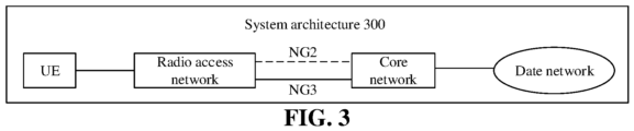
- FIG. 3 is a schematic diagram of a system architecture of a 5GS according to an embodiment of the present application.
- the system architecture 200 may include a UE, a Radio Access Network (RAN), a Core (core network) and a DN.
- the UE, RAN and Core are main components of the architecture.
- the UE, RAN and Core may be divided into a user plane and a control plane.
- the control plane is responsible for the management of a mobile network
- the user plane is responsible for the transmission of service data.
- an NG2 reference point is located between an RAN control plane and a Core control plane; an NG3 reference point is located between an RAN user plane and a Core user plane; and an NG6 reference point is located between the Core user plane and a data network.
- the RAN is similar to a base station in a conventional network, is deployed in a position close to the UE, provides a network access function for an authorized subscriber in a specific area, and can transmit the subscriber data using transmission tunnels with different qualities according to the level of the subscribers and the requirements of services.
- the RAN can manage and rationally use self-resources to provide an access service for the UE according to requirements, and forward the control signal and the subscriber data between the UE and the core network.
- the Core is responsible for maintaining the subscription data of the mobile network, managing network elements of the mobile network, and providing functions such as session management, mobility management, policy management, and security authentication for the UE.
- network access authentication is provided for the UE.
- a network resource is allocated for the UE.
- the network resource is updated for the UE.
- a fast recovery mechanism is provided for the UE.
- the network resource is released for the UE.
- a data routing function is provided for the UE, for example, forwarding uplink data to the DN, or receiving downlink data for UE from the DN and forwarding the data to the RAN, so as to send the data to the UE.
- the DN is a data network that provides a service for the subscriber.
- a client is located in the UE, and a server is located in the data network.
- the data network may be a private network such as a local area network, or may be an external network that is not controlled by operators, such as the Internet, or may be a proprietary network jointly deployed by the operators, for example, for configuring an IP Multimedia Core Network Subsystem (IMS) service.
- IMS IP Multimedia Core Network Subsystem
- FIG. 4 is a detailed architecture that is determined on the basis of FIG. 3 .
- the core network user plane includes a User Plane Function (UPF).
- the core network control plane includes an Authentication Server Function (AUSF), an AMF, an SMF, a Network Slice Selection Function (NSSF), a Network Exposure Function (NEF), a NF Repository Function (NRF), Unified Data Management (UDM), a Policy Control Function (PCF), and an Application Function (AF).
- AUSF Authentication Server Function
- AMF Access Management Function
- NEF Network Exposure Function
- NRF Network Exposure Function
- NRF Network Exposure Function
- NRF Network Exposure Function
- NRF Network Exposure Function
- NRF Network Exposure Function
- NRF Network Exposure Function
- NRF Network Exposure Function
- NRF Network Exposure Function
- NRF Network Exposure Function
- NRF Network Exposure Function
- NRF Network Exposure Function
- NRF Network Exposure Function
- NRF Network Exposure Function
- NRF Network Expo
- an N1 interface is a reference point between the UE and the AMF; an N2 interface is reference points of the RAN and the AMF, which is used to send an NAS message; an N3 interface is a reference point between the RAN and the UPF, which is used to transmit data of the user plane; N4 interface is a reference point between the SMF and the UPF, which is used to transmit information such as tunnel identification information and data caching indication information of N3 connection, and a downlink data notification message; and N6 interface is a reference point between the UPF and the DN, which is used to transmit the data of the user plane.
- the name of the interface between the network elements in FIG. 3 and FIG. 4 is only an example.
- the name of the interface in a specific implementation may be other names, and the embodiments of the present application are not specifically limited thereto.
- the name of each network element (such as SMF, AF, UPF, and the like) included in FIG. 3 and FIG. 4 is also only an example, and does not limit the function of the network element itself.
- the above network elements may also have other names, and the embodiments of the present application are not specifically limited thereto.
- part or all of the above network elements may use the terms in 5G, and may also use other names, which are uniformly described herein, and are not described below again.
- the names of the messages (or signaling) transmitted between the above network elements are only an example, and do not constitute any limitation on the functions of the messages.
- FIG. 5 is a schematic diagram of a relay communication system according to an embodiment of the present application.
- the relay communication system shown in FIG. 5 mainly includes three portions: a wireless subsystem portion, an Evolved Packet Core (EPC) portion and a near field communication service portion.
- EPC Evolved Packet Core
- the wireless subsystem portion which is the EUTRAN, includes one or more eNodeBs, which may further be called an access network device portion in the EPS.
- the EPC portion includes the HSS, the MME, the SGW, the PGW, and the like.
- the near field communication service portion which is a ProSe architecture portion, includes a ProSe Function (PF), a ProSe Application Server (PAS), a relay device (Relay UE), and a remote device (Remote UE).
- PF is used to authorize near field communication of the terminal device, provide discovery assistance between the terminal devices;
- PAS is used to provide specific near field communication service support;
- Relay UE is used to provide relay access support for the Remote UE; and Remote UE is used to access the network by means of the Relay UE, so as to obtain an Internet Protocol (IP) service.
- IP Internet Protocol
- ProSe Applications are installed in both the Relay UE and the Remote UE.
- the relay communication may use different relay modes.
- the relay communication includes a relay mode based on a Non-3rd Generation Partnership Project (3GPP) Inter Working Function (N3IWF) (or called “N3IWF-based relay”), and optionally, the relay communication may further include the following relay modes: a layer 3-based relay mode (or called “Layer-3 UE-to-Network Relays”), or a layer 2-based relay mode (or called “Layer 2 UE-to-Network Relays").
- 3GPP Non-3rd Generation Partnership Project
- N3IWF-based relay Inter Working Function
- the relay communication may further include the following relay modes: a layer 3-based relay mode (or called “Layer-3 UE-to-Network Relays"), or a layer 2-based relay mode (or called “Layer 2 UE-to-Network Relays”).
- the three relay modes are introduced and described respectively below.
- the layer 3-based relay mode is introduced and described.
- a ProSe 5G UE-to-Network Relay entity (hereinafter referred to as "relay device") provides a function for supporting a connection between the remote UE and the network.
- the relay device may not only be applied to a public safety service, but also to a commercial service (such as an interactive service).
- the UE has successfully established a PC5 connection with a ProSe UE-to-Network relay (hereinafter referred to as "relay"), it is considered that the UE is the remote UE for the relay.
- the remote UE may be located within NG-RAN coverage or outside the NG-RAN coverage.
- the remote UE may execute communication path selection between a direct Uu path and an indirect Uu path on the basis of link quality and a configured threshold (which is pre-configured or provided by NG-RAN). For example, if the Uu link quality exceeds a configured threshold, the direct Uu path is selected. Otherwise, the indirect Uu path is selected by executing discovery and selection of the relay.
- a configured threshold which is pre-configured or provided by NG-RAN.
- the relay should relay a unicast service between the remote UE and the network (Uplink (UL) and Downlink (DL)).
- the relay should provide a general function that may relay any IP, Ethernet or Unstructured traffic.
- the relay uses an IP-type PDU session toward 5GC.
- the relay may use an Ethernet-type PDU session or the IP-type PDU session toward the 5GC.
- the relay may use an unstructured-type PDU session or the IP-type PDU session (that is, IP encapsulation/decapsulation of the relay) toward the 5GC.
- an unstructured-type PDU session or the IP-type PDU session that is, IP encapsulation/decapsulation of the relay
- the type of traffic supported over the PC5 reference point is indicated by the relay using a corresponding Relay Service Code (RSC).
- the relay determines the PDU session type based on, such as, near field communication policies/parameters, a UE Routing Selection Policy (URSP) rule, and the RSC.
- URSP UE Routing Selection Policy
- the IP-type PDU session and the Ethernet-type PDU session may be used to support a plurality of remote UEs, and the unstructured-type PDU session may only use to support one remote UE.
- FIG. 7 exemplarily shows a protocol stack for Layer-3 UE-to-Network Relays according to an embodiment of the present application.
- the layer 2-based relay UE provides a forwarding function that may relay any type of traffic over a PC5 link.
- the layer 2-based relay UE provides a function for supporting a connection to 5GS for the remote UE. If UE is considered to be a remote UE if it has successfully established a PC5 link to the layer 2-based relay UE.
- the remote UE may be located within NG-RAN coverage or outside of the NG-RAN coverage.
- FIG. 8 is a protocol stack of a user plane related to a PDU session according to an embodiment of the present application, including a layer 2-based relay UE.
- a PDU layer corresponds to a PDU carried between the remote UE and the DN over the PDU session.
- two endpoints of a Packet Data Convergence Protocol (PDCP) link are the remote UE and gNB.
- the relay function is executed below the PDCP, which means that data security between the remote UE and the gNB can be ensured without exposing raw data at the relay device.
- PDCP Packet Data Convergence Protocol
- Adaptation layers in the relay UE and the gNB may differentiate Signaling Radio Bearers (SRB) and Data Radio Bearers (DRB) for a particular remote UE.
- the adaptation layers are also responsible for mapping PC5 traffic to one or more DRBs of Uu.
- RAN WG2 is responsible for the definition of the adaptation layer.
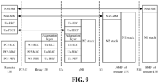
- FIG. 9 is a protocol stack of an NAS connection from a remote UE to NAS-MM and NAS-SM assemblies according to an embodiment of the present application.
- the NAS messages are transparently transferred between the remote UE and the gNB over the layer 2-based relay UE using:
- the role of the relay UE is to relay the PDUs from the signaling radio bearer without any modification.
- FIG. 10 is a schematic diagram of a solution supporting end-to-end security for remote UE traffic transmitted using Layer-3 UE-to-Network Relays according to an embodiment of the present application.
- the relay When access to the N3IWF is used, the relay should be able to relay control plane traffic (NAS) and user plane unicast traffic (UL and DL) between the remote UE and the network toward the N3IWF.
- NAS control plane traffic
- UL and DL user plane unicast traffic
- one-to-one direct communication is used between the remote UE and the relay, so as to achieve unicast traffic.
- the remote UE establishes a signaling IPsec tunnel with the N3IWF over relay access using an Internet Key Exchange (IKE) Protocol.
- IKE Internet Key Exchange
- the subsequent NAS message between the UE and the N3IWF is exchanged via signaling IPsec SA over a Transmission Control Protocol (TCP)/IP.
- TCP Transmission Control Protocol
- the protocol stacks for the control plane before an IPSec tunnel is established and after the IPSec tunnel is established are the same as the untrusted non-3GPP access protocol stack.
- the remote UE supports the NAS-MM (after registration), SMS and PDU session establishment/modification/release processes with the 5GC by transporting corresponding NAS signaling over the signaling IPsec tunnel established with the N3IWF.
- the remote UE sends/receives UP traffic over the relay PDU session established for the remote UE over PC5 relay path via child IPSec SA tunnel to the N3IWF.
- the PCF may provide corresponding URSP rule to assist the remote UE to identify a service that requires access to the N3IWF.
- the UPE and the N3IWF of the relay UE may be configured.
- the user plane protocol stack for layer 3-based relay access via the N3IWF is the same as the user plane protocol stack for untrusted non-3GPP access.
- the PDU session type used between the relay UE and the relay UE UPF is IP.
- the traffic that is transmitted in the PDU layer between the remote UE and the UPF (PDU session anchor) may be IP, Ethernet or unstructured.
- the NG-RAN does not have does not have any different treatment for the traffic of the remote UE with the N3IWF-based relay mode.
- the remote device needs to discover a relay device.
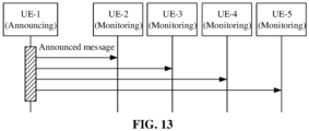
- the relay device can be discovered by the remote device by using a model A and a model B.
- the model A is shown in FIG. 13 , UE-1 announces a message, and the other UEs monitor the message that is announced by the UE-1.
- the message that is announced by the UE-1 is a discovery message.
- the discovery message may carry a device identification of the UE-1 and so on. If the other UEs monitor and receive the discovery message, it is known that the UE-1 may provide a relay service. That is to say, the UE-1 may be used as a relay device.
- the model B is shown in FIG. 14 .
- the UE-1 sends a solicitation message to other UEs, to request for acquiring the relay service.
- the other UEs may send response messages to the UE-1 if the relay service may be provided, so as to indicate that the UE-1 may provide a relay server.
- the device identification of the UE is included in the response message.
- the UE-1 sends solicitation messages to UE-2 to UE-5.
- the UE-2 and the UE-3 which can provide the relay services, may each send a response message to the UE-1.
- the response message sent by the UE-2 may carry the device identification of the UE-2.
- the response message sent by the UE-3 may carry the device identification of the UE-3.
- After the UE-1 receives the response messages it may be known that the UE-2 and the UE-3 can provide the relay services. That is to say, the UE-2 and the UE-3 may be used as the relay devices.
- an embodiment of the present application provides a method for selecting a relay device. The technical solutions of the present application are described below with reference to several embodiments.
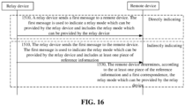
- FIG. 15 is a flowchart of a method for selecting a relay device according to an embodiment of the present application. The method may be applied to a communication system shown in FIG. 1 . The method includes the following operations (S1510 to S1520).
- a relay device sends a first message to a remote device.
- the first message is used to indicate a relay mode which can be provided by the relay device.
- a remote device needs to discover a relay device. It can be seen from the above description that, the relay device can be discovered by the remote device through a announce message (hereinafter referred to as “discovery message") from the relay device, or through the remote device sending a solicitation message and then receiving a response message (hereinafter referred to as "response message for a relay solicitation message").
- the remote device In order to cause the remote device to know relay modes which can be provided by respective relay devices, and facilitate the remote device to select an suitable relay device for relay communication, in the embodiments of the present application, in a process that the remote device discovers the relay device, the first message from the relay device to the remote device is used to indicate the relay mode which can be provided by the relay device.
- the first message is a discovery message or a response message for a relay solicitation message.
- the first message indicates the relay mode which can be provided by the relay device is not limited in the embodiments of the present application.
- the first message directly indicates the relay mode which can be provided by the relay device, so that the remote device may know the relay mode which can be provided by the relay device after receiving the first message.
- the first message indirectly indicates the relay mode which can be provided by the relay device.
- the first message includes information associated with the relay mode which can be provided by the relay device, so that the remote device may determine, according to the associated information, the relay mode which can be provided by the relay device after receiving the first message.
- the remote device selects a first relay device from among at least one relay device on the basis of a relay mode to which the remote device can adapt and a relay mode which can be provided by the at least one relay device.
- the first relay device is used for implementing a communication between the remote device and a network device; and the relay mode which can be provided by the first relay device matches the relay mode to which the remote device can adapt.
- the remote device discovers the relay device
- there is at least one relay device sending the first message to the remote device so that the remote device can know the relay mode which can be provided by the at least one relay device.
- the remote device selects the first relay device from among at least one relay device on the basis of the relay mode which can be provided by the at least one relay device and the relay mode to which the remote device can adapt.
- the first relay device is used to implement the communication between the remote device and the network device, that is to say, achieving relay communication.
- the type of the relay mode includes an N3IWF-based relay mode.
- the type of the relay mode further includes at least one of the following: a layer 3-based relay mode or a layer 2-based relay mode.
- the description of the three relay modes refer to the above method embodiments, and details are not described herein again.
- the type and number of the relay modes to which the remote device can adapt and the type and the number of the relay modes which can be provided by the relay device are not limited.
- there are two relay modes to which the remote device can adapt which respectively are the layer 3-based relay mode and the layer 2-based relay mode.
- There are also two relay modes which can be provided by the relay device which respectively are the layer 2-based relay mode and the N3IWF-based relay mode.
- the remote device may compare the relay mode which can be provided by the at least one relay device with the relay mode to which the relay device can adapt, and select, from the at least one relay device, a relay device, which is the first relay device, corresponding to the relay mode matching the relay mode to which the relay device can adapt.
- a specific manner of determining whether the relay modes match is not limited. Several manners of determining whether the relay modes match provided in the embodiments of the present application are exemplarily shown below.
- the remote device determines that the relay modes match if a relay mode which can be provided is the same as the relay mode to which the remote device can adapt. Therefore, the relay mode which can be provided by the first relay device is the same as the relay mode to which the remote device can adapt. For example, there are two relay modes to which the remote device can adapt, and the two relay modes respectively are the layer 3-based relay mode and the layer 2-based relay mode. Only if there are also two relay modes which can be provided by a certain relay device and the two relay modes respectively are the layer 3-based relay mode and the layer 2-based relay mode, the relay device can be selected for performing relay communication.
- the remote device determines that the relay modes match if the relay mode which can be provided includes the relay mode to which the remote device can adapt. Therefore, the relay mode which can be provided by the first relay device includes the relay mode to which the remote device can adapt. For example, there are two relay modes to which the remote device can adapt and the two relay modes respectively are the layer 3-based relay mode and the layer 2-based relay mode. If there are three relay modes which can be provided by a certain relay device and the three relay modes respectively are the layer 3-based relay mode, the layer 2-based relay mode and the N3IWF-based relay mode, the relay device can be selected for performing relay communication.
- the remote device determines that the relay modes match if the relay mode to which the remote device can adapt includes the relay mode which can be provided. Therefore, the relay mode to which the remote device can adapt includes the relay mode which can be provided by the first relay device. For example, there are three relay modes to which the remote device can adapt and the three relay modes respectively are the layer 3-based relay mode, the layer 2-based relay mode and the N3IWF-based relay mode. If there are two relay modes which can be provided by a certain relay device and the two relay modes respectively are the layer 3-based relay mode and the layer 2-based relay mode, the relay device can be selected for performing relay communication.
- the relay modes which can be provided by a certain relay device only partially match the relay modes to which the remote device can adapt, it may also be considered that the relay mode which can be provided by the relay device matches the relay mode to which the remote device can adapt.
- the two relay modes respectively are the layer 3-based relay mode and the layer 2-based relay mode.
- the relay modes which can be provided by a certain relay device and the two relay modes respectively are the layer 2-based relay mode and the N3IWF-based relay mode
- the relay modes which can be provided by the relay device and the relay modes to which the remote device can adapt include a same relay mode, that is, the layer 2-based relay mode, in this case, it may be determined that the relay mode which can be provided by the relay device matches the relay mode to which the remote device can adapt.
- the relay mode which can be provided by the first relay device matches the relay mode to which the remote device can adapt includes any one of the following: the relay mode which can be provided by the first relay device selected by the remote device is the same as the relay mode to which the remote device can adapt; the relay mode which can be provided by the first relay device selected by the remote device includes the relay mode to which the remote device can adapt; and the relay mode to which the remote device can adapt includes the relay mode which can be provided by the first relay device.
- a message from the relay device to the remote device is set to indicate the relay mode which can be provided by the relay device, so that the remote device can select a suitable relay device from among the at least one relay device according to the relay mode which can be provided by the at least one relay device and the relay mode to which the remote device can adapt, so as to implement relay communication. Since the relay mode which can be provided by the suitable relay device matches the relay mode to which the remote device can adapt, unable relay communication due to the mismatch of the relay modes can be avoided, so that a relay communication process can be efficiently and stably realized.
- the relay device can be selected according to the relay mode which can be provided by the relay device and the relay mode to which the remote device can adapt. Therefore, the relay capabilities of different devices are taken into full consideration, and a selection mechanism of the relay device can be further improved.
- the manner of how the first message indicates the relay mode which can be provided by the relay device is described below.
- the first message includes the relay mode which can be provided by the relay device.
- the relay mode which can be provided by the relay device may directly indicated by the relay device via the first message. That is, the relay mode which can be provided by the relay device may be included in the first message. Therefore, after receiving the first message, the remote device parses the first message to know the relay mode which can be provided by the relay device.
- the first message includes at least one piece of reference information.
- the remote device is required to determine the relay mode which can be provided by the relay device according to the at least one piece reference information included in the first message. Based on this, as shown in FIG. 16 , the above method further includes S1530 in which the remote device determines the relay mode which can be provided by the relay device according to the at least one piece of the reference information and a first correspondence.
- the first correspondence includes a correspondence between at least one piece of the reference information and a relay mode which can be provided by the relay device. According to at least one piece of the reference information, a relay mode corresponding to the reference information can be determined from the first correspondence, so that the determined relay mode can be determined as the relay mode which can be provided by the relay device.
- the manner of determining the first correspondence is not limited.
- the first correspondence is pre-configured in the remote device.
- the first correspondence is pre-configured in a Subscriber Identity Module (SIM) of the remote device.
- SIM Subscriber Identity Module
- the first correspondence is predefined over a communication protocol.
- the first correspondence is sent by a network device corresponding to the remote device to the remote device.
- the network device corresponding to the remote device includes a resident network device for the remote device (which is a network device corresponding to a network on which the remote device resides). Then, the resident network device may carry the first correspondence in a broadcasted system message.
- the network device corresponding to the remote device includes a register network device of the remote device (which is a network device corresponding to a network for registering the remote device). Then, the register network device may carry the first correspondence in a registration message.
- the relay mode which can be provided by the relay device when the relay mode which can be provided by the relay device is directly indicated by the relay device via the first message, that is, when the relay mode which can be provided by the relay device is directly included in the first message, the relay mode which can be provided by the relay device may also correspond to the at least one piece of reference information.
- the relay device determines, according to the at least one piece of reference information, the relay mode which can be provided by the relay device, and carries the relay mode in the first message and send it to the remote device.
- a relay mode which can be provided by the relay device is carried in a message that is sent from the relay device to the remote device, so that the purpose of directly indicating the relay mode which can be provided by the relay device can be achieved.
- reference information is carried by a message that is sent from the relay device to the remote device, so that the remote device may determine, according to the reference information, a relay mode which can be provided by the relay device. Therefore, the purpose of indirectly indicating the relay mode which can be provided by the relay device can be achieved.
- the at least one relay mode to which the remote device can adapt and the at least one relay mode which can be provided by the relay device are respectively described below.
- the at least one relay mode to which the remote device can adapt includes at least one of the following: a relay mode that is supported by the remote device, or a relay mode that is authorized by the remote device.
- the relay mode that is supported by the remote device includes at least one of the following: a relay mode that is supported on the basis of the PLMN, a relay mode that is supported on the basis of the registration area, or a relay mode that is supported on the basis of the RAT.
- the PLMN may be a PLMN where the remote device is currently located, and the relay mode that is supported on the basis of the PLMN may be a relay mode which may be supported by the remote device at the PLMN.
- PLMN 1 supports the layer 2-based relay mode
- PLMN 2 supports the layer 3-based relay mode.
- the remote device supports the layer 2-based relay mode at PLMN 1
- the remote device supports the layer 3-based relay mode at PLMN 2.
- the registration area is a registration area for the remote device, and the relay mode that is supported on the basis of the registration area may be a relay mode which may be supported by the remote device when registering in the registration area.
- the registration area 1 supports the layer 2-based relay mode
- the registration area 2 supports the layer 3-based relay mode.
- the remote device supports the layer 2-based relay mode when registering in the registration area 1
- the remote device supports the layer 3-based relay mode when registering in the registration area 2.
- the relay mode that is supported by the remote device includes relay modes that are supported on the basis of the PLMN and the registration area.
- the PLMN 1 supports the layer 2-based relay mode
- the registration area 1 supports the layer 2-based relay mode and the N3IWF-based relay mode.
- the remote device supports the layer 2-based relay mode when registering in the registration area 1 and being located at the PLMN 1, that is, a relay mode that is supported by both the registration area 1 and the PLMN 1.
- the remote device supports the layer 2-based relay mode and the N3IWF-based relay mode when registering in the registration area 1 and being located at the PLMN 1, that is, the remote device supports all relay modes that are supported by the registration area 1 and the PLMN 1.
- the relay mode that is authorized by the remote device includes at least one of the following: a relay mode that is authorized on the basis of the PLMN, a relay mode that is authorized on the basis of the registration area, or a relay mode that is authorized on the basis of the RAT.
- the PLMN may be a PLMN where the remote device is currently located, and the relay mode that is authorized on the basis of the PLMN may be a relay mode which may be authorized by the remote device at the PLMN.
- the layer 2-based relay mode is authorized by PLMN 1
- the layer 3-based relay mode is authorized by PLMN 2.
- the layer 2-based relay mode is authorized by the remote device at PLMN 1
- the layer 3-based relay mode is authorized by the remote device at PLMN 2.
- the registration area is a registration area for the remote device, and the relay mode that is authorized on the basis of the registration area may be a relay mode which may be authorized by the remote device when registering in the registration area.
- the layer 2-based relay mode is authorized by a registration area 1
- the layer 3-based relay mode is authorized by a registration area 2.
- the layer 2-based relay mode is authorized by the remote device when registering in the registration area 1
- the layer 3-based relay mode is authorized by the remote device when registering in the registration area 2.
- the RAT is a RAT corresponding to the remote device, and the relay mode that is authorized on the basis of the RAT may be a relay mode that may be authorized by the remote device when accessing the network over the RAT.
- the layer 2-based relay mode is authorized by the RAT 1
- the layer 3-based relay mode is authorized by the RAT 2.
- the layer 2-based relay mode is authorized by the remote device when accessing the network over the RAT 1
- the layer 3-based relay mode is authorized by the remote device when accessing the network over the RAT 2.
- the layer 2-based relay mode and the N3IWF-based relay mode are authorized by the remote device when registering in the registration area 1 and being located at the PLMN 1. That is to say, the remote device supports all relay modes that are authorized by the registration area 1 and the PLMN 1.
- the relay mode which can be provided by the relay device includes at least one of the following: a relay mode that is supported by the relay device, a relay mode that is authorized by the relay device, or a relay mode which can be provided by a network device corresponding to the relay device.
- the relay mode which can be provided by the relay device includes: a relay mode that is supported by the relay device, or a relay mode that is authorized by the relay device, or a relay mode which can be provided by a network device corresponding to the relay device, or a relay mode which is supported by the relay device and can be provided by the network device corresponding to the relay device, or a relay mode which is supported and authorized by the relay device, or a relay mode which is authorized by the relay device and can be provided by the network device corresponding to the relay device, or a relay mode which is supported and authorized by the relay device and can be provided by a network device corresponding to the relay device.
- the relay mode that is supported by the relay device includes at least one of the following: a relay mode that is supported on the basis of the PLMN, a relay mode that is supported on the basis of the registration area, or a relay mode that is supported on the basis of the RAT.
- the PLMN may be a PLMN where the relay device is currently located, and the relay mode that is supported on the basis of the PLMN may be a relay mode which may be supported by the relay device at the PLMN.
- PLMN 1 supports the layer 2-based relay mode
- PLMN 2 supports the layer 3-based relay mode.
- the relay device supports the layer 2-based relay mode at PLMN 1
- the relay device supports the layer 3-based relay mode at PLMN 2.
- the registration area is a registration area for the relay device, and the relay mode that is supported on the basis of the registration area may be a relay mode which may be supported by the relay device when registering in the registration area.
- the registration area 1 supports the layer 2-based relay mode
- the registration area 2 supports the layer 3-based relay mode.
- the relay device supports the layer 2-based relay mode when registering in the registration area 1
- the relay device supports the layer 3-based relay mode when registering in the registration area 2.
- the RAT is an RAT corresponding to the relay device, and the relay mode that is supported on the basis of the RAT may be a relay mode that may be supported by the relay device when accessing the network over the RAT.
- the RAT 1 supports the layer 2-based relay mode
- the RAT 2 supports the layer 3-based relay mode.
- the relay device supports the layer 2-based relay mode when accessing the network over the RAT 1
- the relay device supports the layer 3-based relay mode when accessing the network over the RAT 2.
- the relay mode that is supported by the relay device includes relay modes that are supported on the basis of the PLMN and the registration area.
- the PLMN 1 supports the layer 2-based relay mode
- the registration area 1 supports the layer 2-based relay mode and the N3IWF-based relay mode.
- the relay device supports the layer 2-based relay mode when registering in the registration area 1 and being located at the PLMN 1, that is, the relay mode that is supported by both the registration area 1 and the PLMN 1.
- the relay device supports the layer 2-based relay mode and the N3IWF-based relay mode when registering in the registration area 1 and being located at the PLMN 1. That is to say, the relay device supports all relay modes that are supported by the registration area 1 and the PLMN 1.
- the relay mode that is authorized by the relay device includes at least one of the following: a relay mode that is authorized on the basis of the PLMN, a relay mode that is authorized on the basis of the registration area, or a relay mode that is authorized on the basis of the RAT.
- the PLMN may be a PLMN where the relay device is currently located, and the relay mode that is authorized by the PLMN may be a relay mode which may be authorized by the relay device at the PLMN.
- the layer 2-based relay mode is authorized by PLMN 1
- the layer 3-based relay mode is authorized by PLMN 2.
- the layer 2-based relay mode is authorized by the relay device at PLMN 1
- the layer 3-based relay mode is authorized by the relay device at PLMN 2.
- the registration area is a registration area for the relay device, and the relay mode that is authorized on the basis of the registration area may be a relay mode which may be authorized by the relay device when registering in the registration area.
- the layer 2-based relay mode is authorized by the registration area 1
- the layer 3-based relay mode is authorized by the registration area 2.
- the layer 2-based relay mode is authorized by the relay device when registering in the registration area 1
- the layer 3-based relay mode is authorized by the relay device when registering in the registration area 2.
- the RAT is a RAT corresponding to the relay device, and the relay mode that is authorized on the basis of the RAT may be a relay mode that may be authorized by the relay device when accessing a network over the RAT.
- the layer 2-based relay mode is authorized by RAT 1
- the layer 3-based relay mode is authorized by the RAT 2.
- the layer 2-based relay mode is authorized by the relay device when accessing the network over the RAT 1
- the layer 3-based relay mode is authorized by the relay device when accessing the network over the RAT 2.
- the relay mode that is authorized by the relay device includes relay modes that are authorized on the basis of the PLMN and the registration area.
- the layer 2-based relay mode is authorized by the PLMN 1
- the layer 2-based relay mode and the N3IWF-based relay mode are authorized by the registration area 1.
- the layer 2-based relay mode is authorized by the relay device when registering in the registration area 1 and being located at the PLMN 1. That is, the relay device supports a relay mode that is supported by both the registration area 1 and the PLMN 1.
- the layer 2-based relay mode and the N3IWF-based relay mode are authorized by the relay device when registering in the registration area 1 and being located at the PLMN 1. That is to say, the relay device supports all relay modes that are authorized by the registration area 1 and the PLMN 1.
- the network device corresponding to the relay device includes at least one of the following: a resident network device for the relay device, or a register network device for the relay device.
- the resident network device for the relay device is a network device corresponding to a network on which the relay device is resided.
- the register network device for the relay device is a network device corresponding to a network for registering the relay device.
- a relay mode which can be provided by the resident network device for the relay device is carried in a system message broadcasted by the resident network device for the relay device. That is to say, the resident network device carries the relay mode which can be provided by the resident network device in the system message broadcasted by the resident network device.
- a relay mode which can be provided by the register network device for the relay device is carried in a registration message sent by the register network device. That is to say, the register network device carries the relay mode which can be provided by the register network device in the registration message.
- the method for selecting the relay device provided in the embodiments of the present application is described from the perspective of interaction between the remote device and the relay device.
- the steps executed by the remote device may be separately implemented as a method for selecting a relay device at the remote device side.
- the steps executed by the relay device may be separately implemented as a method for selecting a relay device at the relay device side.
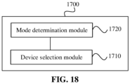
- FIG. 17 is a block diagram of an apparatus for selecting a relay device according to an embodiment of the present application.
- the apparatus has the function of implementing the above method examples on the remote device side, and the function may be implemented by means of hardware or by means of hardware executing corresponding software.
- the apparatus may be the remote device introduced above, or may be disposed in the remote device.
- the apparatus 1700 includes a device selection module 1710.
- the device selection module 1710 is configured to select a first relay device from among at least one relay device on the basis of a relay mode to which the remote device can adapt and a relay mode which can be provided by the at least one relay device.
- the first relay device is used for implementing a communication between the remote device and a network device.
- the relay mode which can be provided by the first relay device matches the relay mode to which the remote device can adapt.
- the relay mode which can be provided by the first relay device matches the relay mode to which the remote device can adapt in a manner including any one of the following: the relay mode which can be provided by the first relay device is the same as the relay mode to which the remote device can adapt; the relay mode which can be provided by the first relay device includes the relay mode to which the remote device can adapt; and the relay mode to which the remote device can adapt includes the relay mode which can be provided by the first relay device.
- the relay mode to which the remote device can adapt includes at least one of the following: a relay mode that is supported by the remote device, or a relay mode that is authorized by the remote device.
- the relay mode that is supported by the remote device includes at least one of the following: a relay mode that is supported on the basis of the PLMN, a relay mode that is supported on the basis of the registration area, or a relay mode that is supported on the basis of the RAT.
- the relay mode that is authorized by the remote device includes at least one of the following: a relay mode that is authorized on the basis of the PLMN, a relay mode that is authorized on the basis of the registration area, or a relay mode that is authorized on the basis of the RAT.
- the relay mode that is supported by the relay device includes at least one of the following: a relay mode that is supported on the basis of the PLMN, a relay mode that is supported on the basis of the registration area, or a relay mode that is supported on the basis of the RAT.
- the network device corresponding to the relay device includes the register network device for the relay device; and a relay mode which can be provided by the register network device for the relay device is carried in a registration message that is sent by the register network device for the relay device.
- the relay mode which can be provided by the relay device is carried in a first message.
- the first message is a discovery message or a response message for a relay solicitation message sent by the remote device.
- the relay mode which can be provided by the relay device corresponds to at least one piece of the following reference information: the PLMN, the RAT, the RSC, the DNN, or the network slice.
- the at least one piece of the reference information is carried in the first message.
- the first message is a discovery message or a response message for a relay solicitation message sent by the remote device.
- the apparatus 1700 further includes: a mode determination module 1720, configured to, determine, according to the at least one piece of the reference information and a first correspondence, the relay mode which can be provided by the relay device.
- the first correspondence includes a correspondence between at least one piece of the reference information and a relay mode which can be provided by the relay device.
- the first correspondence is pre-configured in the remote device.
- the type of the relay mode includes an N3IWF-based relay mode, and the type of the relay mode may further include at least one of the following: a layer 3-based relay mode or a layer 2-based relay mode.
- a message from the relay device to the remote device is set to indicate a relay mode which can be provided by the relay device, so that the remote device can select a suitable relay device from among at least one relay device according to relay modes which can be provided by the at least one relay device and a relay mode to which the remote device can adapt, so as to implement relay communication. Since a relay mode which can be provided by the suitable relay device matches the relay mode to which the remote device can adapt, unable relay communication due to the mismatch of the relay modes can be avoided, so that a relay communication process can be efficiently and stably realized.
- the relay device can be selected according to the relay mode which can be provided by the relay device and the relay mode to which the remote device can adapt. Therefore, the relay capabilities of different devices are taken into full consideration, and a selection mechanism of the relay device can be further improved.
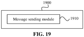
- FIG. 19 is a block diagram of an apparatus for selecting a relay device according to an embodiment of the present application.
- the apparatus has the function of implementing the above method examples on the relay device side, and the function may be implemented by means of hardware or by means of hardware executing corresponding software.
- the apparatus may be the relay device introduced above, or may be disposed in the relay device.
- the apparatus 1900 includes a message sending module 1910.
- the message sending module 1910 is configured to send a first message to a remote device.
- the first message is used to indicate a relay mode which can be provided by the relay device.
- the first message is a discovery message or a response message for a relay solicitation message sent by the remote device.
- the relay mode which can be provided by the relay device includes at least one of the following: a relay mode that is supported by the relay device, a relay mode that is authorized by the relay device, or a relay mode which is able to be provided by a network device corresponding to the relay device.
- the relay mode that is supported by the relay device includes at least one of the following: a relay mode that is supported on the basis of a PLMN, a relay mode that is supported on the basis of a registration area, or a relay mode that is supported on the basis of an RAT.
- the relay mode that is authorized by the relay device includes at least one of the following: a relay mode that is authorized on the basis of the PLMN, a relay mode that is authorized on the basis of the registration area, or a relay mode that is authorized on the basis of the RAT.
- the network device corresponding to the relay device includes at least one of the following: a resident network device for the relay device, or a register network device for the relay device.
- the network device corresponding to the relay device includes the resident network device for the relay device.
- a relay mode which can be provided by the resident network device for the relay device is carried in a system message that is announced by the resident network device for the relay device.
- the network device corresponding to the relay device includes the register network device for the relay device; and a relay mode which can be provided by the register network device for the relay device is carried in a registration message that is sent by the register network device for the relay device.
- the first message includes the relay mode which can be provided by the relay device.
- the first message includes at least one piece of reference information.
- a type of the relay mode includes an N3IWF-based relay mode, and the type of the relay mode may further include at least one of the following: a layer 3-based relay mode or a layer 2-based relay mode.
- a message from the relay device to the remote device is set to indicate a relay mode which can be provided by the relay device, so that the remote device can select a suitable relay device from among at least one relay device according to relay modes which can be provided by the at least one relay device and the relay mode to which the remote device can adapt, so as to implement relay communication. Since the relay mode which can be provided by the suitable relay device matches the relay mode to which the remote device can adapt, unable relay communication due to the mismatch of the relay modes can be avoided, so that a relay communication process can be efficiently and stably realized.
- the apparatus provided in the above embodiment implements functions of the apparatus, only the division of the above functional modules is used as an example for description.
- the above function can be allocated to and performed by different function modules according to actual requirements. That is to say, a content structure of the device is divided into different function modules, so as to perform all or part of the functions described above.
- FIG. 20 is a schematic structural diagram of a remote device 200 according to the present invention.
- the remote device may be configured to execute the method for selecting the relay device at the remote device side.
- the remote device 200 may include a processor 201 and a transceiver 202 connected to the processor 201.
- the processor 201 includes one or more processing cores.
- the processor 201 executes function applications and information processing by operating software programs and modules.
- the transceiver 202 includes a receiver and a transmitter.
- the transceiver 202 is a communication chip.
- the remote device 200 further includes a memory and a bus.
- the memory is connected to the processor via the bus.
- the memory may be configured to store a computer program.
- the processor is configured to execute the computer program, so as to implement steps in the above method embodiments that are executed by the remote device.
- the memory may be implemented by any type of volatile or non-volatile storage device or a combination thereof.
- the volatile or non-volatile storage device includes, but is not limited to, a Random-Access Memory (RAM), a Read-Only Memory (ROM), an Erasable Programmable Read-Only Memory (EPROM), an Electrically Erasable Programmable Read-Only Memory (EEPROM), a flash memory or other solid state storage technologies, a Compact Disc Read-Only Memory (CD-ROM), a Digital Video Disc (DVD), or other optical storage, tape cartridges, magnetic tape, disk storage or other magnetic storage devices.
- RAM Random-Access Memory
- ROM Read-Only Memory
- EPROM Erasable Programmable Read-Only Memory
- EEPROM Electrically Erasable Programmable Read-Only Memory
- flash memory or other solid state storage technologies
- CD-ROM Compact Disc Read-Only Memory
- DVD Digital Video Disc
- the processor 201 is configured to select a first relay device from among at least one relay device on the basis of a relay mode to which the remote device can adapt and a relay mode which can be provided by the at least one relay device.
- the first relay device is used for implementing a communication between the remote device and a network device.
- a relay mode which can be provided by the first relay device matches the relay mode to which the remote device can adapt.
- the relay mode to which the remote device can adapt includes at least one of the following: a relay mode that is supported by the remote device, or a relay mode that is authorized by the remote device.
- the relay mode which can be provided by the relay device includes at least one of the following: a relay mode that is supported by the relay device, a relay mode that is authorized by the relay device, or a relay mode which is able to be provided by a network device corresponding to the relay device.
- the network device corresponding to the relay device includes at least one of the following: a resident network device for the relay device, or a register network device for the relay device.
- the network device corresponding to the relay device includes the resident network device for the relay device.
- a relay mode which can be provided by the resident network device for the relay device is carried in a system message that is announced by the resident network device for the relay device.
- the network device corresponding to the relay device includes the register network device for the relay device; and a relay mode which can be provided by the register network device for the relay device is carried in a registration message that is sent by the register network device for the relay device.
- the relay mode which can be provided by the relay device is carried in a first message.
- the first message is a discovery message or a response message for a relay solicitation message sent by the remote device.
- the relay mode which can be provided by the relay device corresponds to at least one piece of the following reference information: the PLMN, the RAT, the RSC, the DNN, or the network slice.
- the at least one piece of the reference information is carried in the first message.
- the first message is a discovery message or a response message for a relay solicitation message sent by the remote device.
- the processor 201 is configured to determine, according to the at least one piece of the reference information and a first correspondence, the relay mode which can be provided by the relay device.
- the first correspondence includes a correspondence between at least one piece of the reference information and a relay mode which can be provided by the relay device.
- the first correspondence is pre-configured in the remote device.
- the type of the relay mode includes an N3IWF-based relay mode, and the type of the relay mode may further include at least one of the following: a layer 3-based relay mode or a layer 2-based relay mode.
- FIG. 21 is a schematic structural diagram of a relay device 210 according to the present invention.
- the relay device may be configured to execute the method for selecting the relay device at the relay device side.
- the relay device 210 may include a processor 211 and a transceiver 212 connected to the processor 211.
- the processor 211 includes one or more processing cores.
- the processor 211 executes function applications and information processing by operating software programs and modules.
- the transceiver 212 includes a receiver and a transmitter.
- the transceiver 212 is a communication chip.
- the relay device 210 further includes a memory and a bus.
- the memory is connected to the processor via the bus.
- the memory may be configured to store a computer program.
- the processor is configured to execute the computer program, so as to implement steps in the above method embodiments that are executed by the relay device.
- the transceiver 212 is configured to send a first message to a remote device.
- the first message is used to indicate a relay mode which can be provided by the relay device.
- the first message is a discovery message or a response message for a relay solicitation message sent by the remote device.
- the relay mode which can be provided by the relay device includes at least one of the following: a relay mode that is supported by the relay device, a relay mode that is authorized by the relay device, or a relay mode which is able to be provided by a network device corresponding to the relay device.
- the relay mode that is supported by the relay device includes at least one of the following: a relay mode that is supported on the basis of a PLMN, a relay mode that is supported on the basis of a registration area, or a relay mode that is supported on the basis of an RAT.
- the relay mode that is authorized by the relay device includes at least one of the following: a relay mode that is authorized on the basis of the PLMN, a relay mode that is authorized on the basis of the registration area, or a relay mode that is authorized on the basis of the RAT.
- the network device corresponding to the relay device includes at least one of the following: a resident network device for the relay device, or a register network device for the relay device.
- the network device corresponding to the relay device includes the resident network device for the relay device.
- a relay mode which can be provided by the resident network device for the relay device is carried in a system message that is announced by the resident network device for the relay device.
- the network device corresponding to the relay device includes the register network device for the relay device; and a relay mode which can be provided by the register network device for the relay device is carried in a registration message that is sent by the register network device for the relay device.
- the first message includes the relay mode which can be provided by the relay device.
- the relay mode which can be provided by the relay device corresponds to at least one piece of the following reference information: the PLMN, the RAT, an RSC, a DNN, or the network slice.
- the first message includes at least one piece of reference information.
- the type of the relay mode includes an N3IWF-based relay mode, and the type of the relay mode may further include at least one of the following: a layer 3-based relay mode or a layer 2-based relay mode.
- An embodiment not being part of the invention provides a computer-readable storage medium.
- the storage medium stores a computer program.
- the computer program is executed by a processor of a remote device, so as to implement the method for selecting the relay device at the remote device side as described above.
- An embodiment not being part of the invention further provides a computer-readable storage medium.
- the storage medium stores a computer program.
- the computer program is executed by a processor of a relay device, so as to implement the method for selecting the relay device at the relay device side as described above.
- An embodiment not being part of the invention further provides a chip.
- the storage medium stores a computer program.
- the computer program is executed by a processor of a relay device, so as to implement the method for selecting the relay device on the relay device side as described above.
- An embodiment not being part of the invention further provides a chip.
- the chip includes a programmable logic circuit and/or a program instruction. When the chip is operated on a relay device, the method for selecting the relay device at the relay device side as described above is implemented.
- An embodiment not being part of the invention further provides a computer program product.
- the computer program product is operated on a remote device, the method for selecting the relay device at the remote device side as described above is implemented.
- An embodiment not being part of the invention further provides a computer program product.
- the computer program product When the computer program product is operated on a relay device, the method for selecting the relay device at the relay device side as described above is implemented.
- the computer-readable medium includes a computer storage medium and a communication medium.
- the communication medium includes any media transmitting a computer program from one place to another place.
- the storage medium may be any available media capable of being stored by a general or special computer.
Landscapes
- Engineering & Computer Science (AREA)
- Computer Networks & Wireless Communication (AREA)
- Signal Processing (AREA)
- Databases & Information Systems (AREA)
- Mobile Radio Communication Systems (AREA)
- Data Exchanges In Wide-Area Networks (AREA)
Claims (15)
- Verfahren zum Auswählen einer Weiterleitungsvorrichtung, wobei das Verfahren durch eine entfernte Vorrichtung ausgeführt wird und Folgendes umfasst:Auswählen (1520) einer ersten Weiterleitungsvorrichtung aus mindestens einer Weiterleitungsvorrichtung anhand mindestens einer Weiterleitungsbetriebsart, an die sich die entfernte Vorrichtung anpassen kann, und mindestens einer Weiterleitungsbetriebsart, die durch die mindestens eine Weiterleitungsvorrichtung bereitgestellt werden kann, wobeidie erste Weiterleitungsvorrichtung verwendet wird, um eine Kommunikation zwischen der entfernten Vorrichtung und einer Netzvorrichtung einzurichten, und wobei mindestens eine Weiterleitungsbetriebsart, die durch die erste Weiterleitungsvorrichtung bereitgestellt werden kann, mit der mindestens einen Weiterleitungsbetriebsart übereinstimmt, an die sich die entfernte Vorrichtung anpassen kann, unddie mindestens eine Weiterleitungsbetriebsart, die durch die mindestens eine Weiterleitungsvorrichtung bereitgestellt werden kann, einem Abschnitt folgender Referenzinformationen entspricht: einem Weiterleitungsdienstcode, RSC, und wobei der Abschnitt der Referenzinformationen in einer ersten Nachricht übertragen wird, wobei die erste Nachricht durch die entfernte Vorrichtung von der mindestens einen Weiterleitungsvorrichtung empfangen wird (1510) und die erste Nachricht eine Auffindungsnachricht oder eine Antwortnachricht für eine Weiterleitungsanfragenachricht, die durch die entfernte Vorrichtung gesendet wird, ist, und das Verfahren ferner Folgendes umfasst:Bestimmen (1530) gemäß dem Abschnitt der Referenzinformationen und einer ersten Übereinstimmung der mindestens einen Weiterleitungsbetriebsart, die durch die mindestens eine Weiterleitungsvorrichtung bereitgestellt werden kann, wobeidie erste Übereinstimmung eine Übereinstimmung zwischen mindestens einem Abschnitt der Referenzinformationen und mindestens einer Weiterleitungsbetriebsart, die durch eine Weiterleitungsvorrichtung bereitgestellt werden kann, umfasst und die mindestens eine Weiterleitungsbetriebsart, die durch die mindestens eine Weiterleitungsvorrichtung bereitgestellt werden kann, eine Weiterleitungsbetriebsart umfasst, die auf einer Nicht-"3rd Generation Partnership Project, 3GPP, Inter Working Function", N3IWF, beruht.
- Verfahren nach Anspruch 1, wobei die mindestens eine Weiterleitungsbetriebsart, an die sich die entfernte Vorrichtung anpassen kann, mindestens eines des Folgenden umfasst:mindestens eine Weiterleitungsbetriebsart, die durch die entfernte Vorrichtung unterstützt wird, odermindestens eine Weiterleitungsbetriebsart, die durch die entfernte Vorrichtung autorisiert ist.
- Verfahren nach Anspruch 1 oder 2, wobei die mindestens eine Weiterleitungsbetriebsart, die durch die mindestens eine Weiterleitungsvorrichtung bereitgestellt werden kann, mindestens eines des Folgenden umfasst:mindestens eine Weiterleitungsbetriebsart, die durch die mindestens eine Weiterleitungsvorrichtung unterstützt wird;mindestens eine Weiterleitungsbetriebsart, die durch die mindestens eine Weiterleitungsvorrichtung autorisiert ist; odermindestens eine Weiterleitungsbetriebsart, die durch eine Netzvorrichtung bereitgestellt werden kann, die der mindestens einen Weiterleitungsvorrichtung entspricht.
- Verfahren nach Anspruch 1, wobei die erste Übereinstimmung in der entfernten Vorrichtung vorkonfiguriert ist.
- Verfahren nach einem der Ansprüche 1 bis 4, wobei die mindestens eine Weiterleitungsbetriebsart, die durch die mindestens eine Weiterleitungsvorrichtung bereitgestellt werden kann, ferner Folgendes umfasst:eine auf Schicht 3 beruhende Weiterleitungsbetriebsart; odereine auf Schicht 2 beruhende Weiterleitungsbetriebsart.
- Verfahren, das durch eine Weiterleitungsvorrichtung ausgeführt wird und Folgendes umfasst:Senden (1510) einer ersten Nachricht an eine entfernte Vorrichtung, wobei die erste Nachricht mindestens eine Weiterleitungsbetriebsart angibt, die durch die Weiterleitungsvorrichtung bereitgestellt werden kann und wobei die mindestens eine Weiterleitungsbetriebsart, die durch die Weiterleitungsvorrichtung bereitgestellt werden kann, einem Abschnitt folgender Referenzinformationen entspricht: einem Weiterleitungsdienstcode, RSC, wobei die erste Nachricht den Abschnitt der Referenzinformationen umfasst und wobei die mindestens eine Weiterleitungsbetriebsart, die durch die Weiterleitungsvorrichtung bereitgestellt werden kann, eine Weiterleitungsbetriebsart umfasst, die auf einer Nicht-"3rd Generation Partnership Project, 3GPP, Inter Working Function", N3IWF, beruht, unddie erste Nachricht eine Auffindungsnachricht oder eine Antwortnachricht für eine Weiterleitungsanfragenachricht, die durch die entfernte Vorrichtung gesendet wird, ist.
- Verfahren nach Anspruch 6, wobei die mindestens eine Weiterleitungsbetriebsart, die durch die Weiterleitungsvorrichtung bereitgestellt werden kann, mindestens eines des Folgenden umfasst:mindestens eine Weiterleitungsbetriebsart, die durch die Weiterleitungsvorrichtung unterstützt wird;mindestens eine Weiterleitungsbetriebsart, die durch die Weiterleitungsvorrichtung autorisiert ist; odermindestens eine Weiterleitungsbetriebsart, die durch eine Netzvorrichtung bereitgestellt werden kann, die der Weiterleitungsvorrichtung entspricht.
- Verfahren nach Anspruch 6 oder 7, wobei die mindestens eine Weiterleitungsbetriebsart, die durch die Weiterleitungsvorrichtung bereitgestellt werden kann, ferner Folgendes umfasst:eine auf Schicht 3 beruhende Weiterleitungsbetriebsart; odereine auf Schicht 2 beruhende Weiterleitungsbetriebsart.
- Vorrichtung (1700) zum Auswählen einer Weiterleitungsvorrichtung, wobei die Vorrichtung in einer entfernten Vorrichtung angeordnet ist und Folgendes umfasst:ein Vorrichtungsauswahlmodul (1710), das konfiguriert ist, eine erste Weiterleitungsvorrichtung aus mindestens einer Weiterleitungsvorrichtung anhand mindestens einer Weiterleitungsbetriebsart, an die sich die entfernte Vorrichtung anpassen kann, und mindestens einer Weiterleitungsbetriebsart, die durch die mindestens eine Weiterleitungsvorrichtung bereitgestellt werden kann, auszuwählen, wobeidie erste Weiterleitungsvorrichtung verwendet wird, um eine Kommunikation zwischen der entfernten Vorrichtung und einer Netzvorrichtung zu implementieren und wobei mindestens eine Weiterleitungsbetriebsart, die durch die erste Weiterleitungsvorrichtung bereitgestellt werden kann, mit der mindestens einen Weiterleitungsbetriebsart übereinstimmt, an die sich die entfernte Vorrichtung anpassen kann, unddie mindestens eine Weiterleitungsbetriebsart, die durch die mindestens eine Weiterleitungsvorrichtung bereitgestellt werden kann, einem Abschnitt folgender Referenzinformationen entspricht: einem Weiterleitungsdienstcode, RSC, wobei der Abschnitt der Referenzinformationen in einer ersten Nachricht übertragen wird, wobei die erste Nachricht durch die entfernte Vorrichtung von der mindestens einen Weiterleitungsvorrichtung empfangen wird und die erste Nachricht eine Auffindungsnachricht oder eine Antwortnachricht für eine Weiterleitungsanfragenachricht, die durch die entfernte Vorrichtung gesendet wird, ist, und die Vorrichtung ferner Folgendes umfasst:ein Betriebsartbestimmungsmodul (1720), das konfiguriert ist, gemäß dem Abschnitt der Referenzinformationen und einer ersten Übereinstimmung die mindestens eine Weiterleitungsbetriebsart, die durch die mindestens eine Weiterleitungsvorrichtung bereitgestellt werden kann, zu bestimmen, wobeidie erste Übereinstimmung eine Übereinstimmung zwischen mindestens einem Abschnitt der Referenzinformationen und mindestens einer Weiterleitungsbetriebsart umfasst, die durch eine Weiterleitungsvorrichtung bereitgestellt werden kann, und die mindestens eine Weiterleitungsbetriebsart, die durch die mindestens eine Weiterleitungsvorrichtung bereitgestellt werden kann, eine Weiterleitungsbetriebsart umfasst, die auf einer Nicht-"3rd Generation Partnership Project, 3GPP, Inter Working Function", N3IWF, beruht.
- Vorrichtung (1700) nach Anspruch 9, wobei die mindestens eine Weiterleitungsbetriebsart, an die sich die entfernte Vorrichtung anpassen kann, Folgendes umfasst:mindestens eine Weiterleitungsbetriebsart, die durch die entfernte Vorrichtung unterstützt wird; odermindestens eine Weiterleitungsbetriebsart, die durch die entfernte Vorrichtung autorisiert ist.
- Vorrichtung (1700) nach Anspruch 9 oder 10, wobei die mindestens eine Weiterleitungsbetriebsart, die durch die mindestens eine Weiterleitungsvorrichtung bereitgestellt werden kann, mindestens eines des Folgenden umfasst:mindestens eine Weiterleitungsbetriebsart, die durch die mindestens eine Weiterleitungsvorrichtung unterstützt wird;mindestens eine Weiterleitungsbetriebsart, die durch die mindestens eine Weiterleitungsvorrichtung autorisiert ist; odermindestens eine Weiterleitungsbetriebsart, die durch eine Netzvorrichtung bereitgestellt werden kann, die der mindestens einen Weiterleitungsvorrichtung entspricht.
- Vorrichtung (1700) nach Anspruch 9, wobei die erste Übereinstimmung in der entfernten Vorrichtung vorkonfiguriert ist.
- Vorrichtung (1700) nach einem der Ansprüche 9 bis 12, wobei die mindestens eine Weiterleitungsbetriebsart, die durch die mindestens eine Weiterleitungsvorrichtung bereitgestellt werden kann, ferner Folgendes umfasst:eine auf Schicht 3 beruhende Weiterleitungsbetriebsart; odereine auf Schicht 2 beruhende Weiterleitungsbetriebsart.
- Vorrichtung (1900), die in einer Weiterleitungsvorrichtung angeordnet ist und Folgendes umfasst:ein Nachrichtensendemodul (1910), das konfiguriert ist, eine erste Nachricht an eine entfernte Vorrichtung zu senden, wobei die erste Nachricht mindestens eine Weiterleitungsbetriebsart angibt, die durch die Weiterleitungsvorrichtung bereitgestellt werden kann, und wobei die mindestens eine Weiterleitungsbetriebsart, die durch die Weiterleitungsvorrichtung bereitgestellt werden kann, einem Abschnitt folgender Referenzinformationen entspricht: einem Weiterleitungsdienstcode, RSC, und wobei die erste Nachricht den Abschnitt der Referenzinformationen umfasst und wobei die mindestens eine Weiterleitungsbetriebsart, die durch die Weiterleitungsvorrichtung bereitgestellt werden kann, eine Weiterleitungsbetriebsart umfasst, die auf einer Nicht-"3rd Generation Partnership Project, 3GPP, Inter Working Function", N3IWF, beruht, unddie erste Nachricht eine Auffindungsnachricht oder eine Antwortnachricht für eine Weiterleitungsanfragenachricht, die durch die entfernte Vorrichtung gesendet wird, ist.
- Vorrichtung (1900) nach Anspruch 14, wobei die mindestens eine Weiterleitungsbetriebsart, die durch die Weiterleitungsvorrichtung bereitgestellt werden kann, Folgendes umfasst:mindestens eine Weiterleitungsbetriebsart, die durch die Weiterleitungsvorrichtung unterstützt wird;mindestens eine Weiterleitungsbetriebsart, die durch die Weiterleitungsvorrichtung autorisiert ist, odermindestens eine Weiterleitungsbetriebsart, die durch eine Netzvorrichtung, die der Weiterleitungsvorrichtung entspricht, bereitgestellt werden kann.
Applications Claiming Priority (1)
| Application Number | Priority Date | Filing Date | Title |
|---|---|---|---|
| PCT/CN2020/118967 WO2022067540A1 (zh) | 2020-09-29 | 2020-09-29 | 中继设备的选择方法、装置、设备及存储介质 |
Publications (3)
| Publication Number | Publication Date |
|---|---|
| EP4156854A1 EP4156854A1 (de) | 2023-03-29 |
| EP4156854A4 EP4156854A4 (de) | 2023-05-10 |
| EP4156854B1 true EP4156854B1 (de) | 2025-04-23 |
Family
ID=80949386
Family Applications (1)
| Application Number | Title | Priority Date | Filing Date |
|---|---|---|---|
| EP20955565.5A Active EP4156854B1 (de) | 2020-09-29 | 2020-09-29 | Verfahren und vorrichtung zur auswahl einer relaisvorrichtung sowie vorrichtung und speichermedium |
Country Status (4)
| Country | Link |
|---|---|
| US (1) | US12598660B2 (de) |
| EP (1) | EP4156854B1 (de) |
| CN (2) | CN116193415A (de) |
| WO (1) | WO2022067540A1 (de) |
Families Citing this family (4)
| Publication number | Priority date | Publication date | Assignee | Title |
|---|---|---|---|---|
| CN118945654A (zh) * | 2023-05-11 | 2024-11-12 | 华为技术有限公司 | 一种通信方法及装置 |
| CN116600283B (zh) * | 2023-07-19 | 2023-10-03 | 中国电信股份有限公司 | 网络接入方式识别方法、装置、通信设备、介质及产品 |
| CN120091273A (zh) * | 2023-12-01 | 2025-06-03 | 华为技术有限公司 | 一种通信方法及装置 |
| CN117768971A (zh) * | 2023-12-27 | 2024-03-26 | 维沃移动通信有限公司 | 数据传输方法、装置、中继设备、网络设备及介质 |
Family Cites Families (19)
| Publication number | Priority date | Publication date | Assignee | Title |
|---|---|---|---|---|
| US8837443B2 (en) * | 2010-08-13 | 2014-09-16 | Sharp Kabushiki Kaisha | Reducing congestion in wireless communication networks |
| WO2014106336A1 (en) * | 2013-01-06 | 2014-07-10 | Telefonaktiebolaget L M Ericsson (Publ) | Method and apparatus for adaptive resource allocation |
| US9713072B2 (en) * | 2013-07-29 | 2017-07-18 | Htc Corporation | Method of relay discovery and communication in a wireless communications system |
| US9955334B2 (en) * | 2015-01-09 | 2018-04-24 | Acer Incorporated | Method of performing proximity discovery for network entity and user equipment |
| US9826460B2 (en) * | 2015-05-14 | 2017-11-21 | Qualcomm Incorporated | Measurement of D2D channels |
| CN106304257A (zh) * | 2015-05-15 | 2017-01-04 | 上海贝尔股份有限公司 | 选择ue到网络的中继的方法和用于中继发现的同步方法 |
| CN106888494B (zh) * | 2015-12-15 | 2020-10-27 | 上海诺基亚贝尔股份有限公司 | 一种用于选择中继ue的方法、装置和系统 |
| KR102493536B1 (ko) | 2016-06-08 | 2023-01-31 | 삼성전자주식회사 | 통신 단말의 릴레이 통신 방법 및 그 통신 단말 |
| WO2018072157A1 (zh) * | 2016-10-19 | 2018-04-26 | 华为技术有限公司 | 一种控制设备到设备间发现的方法及相关设备 |
| CN109716700B (zh) * | 2016-11-17 | 2021-06-22 | 华为技术有限公司 | 一种指示方法及相关设备 |
| US10341823B2 (en) * | 2016-12-30 | 2019-07-02 | Kodiak Networks Inc. | System and method for direct mode push to talk communication protocols |
| US10292087B2 (en) * | 2017-02-01 | 2019-05-14 | Futurewei Technologies, Inc. | System and method for access barring |
| WO2018145084A1 (en) * | 2017-02-06 | 2018-08-09 | Intel IP Corporation | User equipment (ue), evolved node-b (enb) and methods to indicate parameters for a relay arrangement |
| US10932175B2 (en) * | 2017-03-21 | 2021-02-23 | Lg Electronics Inc. | Method for relay terminal to select remote terminal where access control is applied due to network congestion and relay terminal performing method |
| EP3603143B1 (de) * | 2017-04-27 | 2023-09-13 | Samsung Electronics Co., Ltd. | Verfahren zur erfassung von informationen über netzwerkslice-verfügbaren bereich |
| CN108809897A (zh) * | 2017-04-28 | 2018-11-13 | 中兴通讯股份有限公司 | 一种中继发现及中继转发方法、设备和存储介质 |
| CN109246793B (zh) * | 2017-05-17 | 2021-05-18 | 华为技术有限公司 | 多链接的数据传输方法及装置 |
| CN110098858A (zh) * | 2018-01-30 | 2019-08-06 | 电信科学技术研究院有限公司 | 一种中继工作模式配置方法及终端 |
| CN110099423A (zh) * | 2018-01-30 | 2019-08-06 | 电信科学技术研究院有限公司 | 一种中继工作模式的选择方法、装置及设备 |
-
2020
- 2020-09-29 CN CN202310183158.6A patent/CN116193415A/zh active Pending
- 2020-09-29 CN CN202080101603.4A patent/CN115669213A/zh active Pending
- 2020-09-29 WO PCT/CN2020/118967 patent/WO2022067540A1/zh not_active Ceased
- 2020-09-29 EP EP20955565.5A patent/EP4156854B1/de active Active
-
2022
- 2022-12-22 US US18/145,845 patent/US12598660B2/en active Active
Also Published As
| Publication number | Publication date |
|---|---|
| EP4156854A4 (de) | 2023-05-10 |
| WO2022067540A1 (zh) | 2022-04-07 |
| US20230126582A1 (en) | 2023-04-27 |
| CN115669213A (zh) | 2023-01-31 |
| US12598660B2 (en) | 2026-04-07 |
| CN116193415A (zh) | 2023-05-30 |
| EP4156854A1 (de) | 2023-03-29 |
Similar Documents
| Publication | Publication Date | Title |
|---|---|---|
| US11979926B2 (en) | Systems, methods, and apparatuses for enabling relay services for user equipment to access 5GC via a residential gateway | |
| US12156114B2 (en) | Layer 2 UE to UE data forwarding | |
| EP4042830B1 (de) | Freigabe mehrerer pdu-sitzungen im bulk-verfahren | |
| EP3780790B1 (de) | Vorrichtungen und verfahren zur richtlinienverwaltung von benutzergeräten in drahtloskommunikationssystem | |
| EP4021073B1 (de) | Verfahren zum verschieben einer ims-sprachsitzung von einem nicht-3gpp- zu einem 3gpp-zugang | |
| US11937337B2 (en) | Methods and apparatuses for alternative data over non-access stratum, donas, data delivery in a roaming scenario | |
| US12598660B2 (en) | Method for selecting relay device, remote device and relay device | |
| EP4207891B1 (de) | Vorrichtungen und verfahren zur richtlinienverwaltung eines benutzergeräts in einem drahtloskommunikationssystem | |
| US11553549B2 (en) | Multi-access PDU session state synchronization between UE and network | |
| US11503667B2 (en) | Enhancement for multi-access PDU session release | |
| WO2019172629A1 (ko) | 무선 통신 시스템에서 무선 접속 기술을 스위칭하기 위한 장치 및 방법 | |
| EP4216622A2 (de) | Netzwerkregistrierungsverfahren für verkehrssteuerung und vorrichtung zur unterstützung davon | |
| US12335794B2 (en) | QoS update handling alternatives during Xn HO | |
| US20230189208A1 (en) | Processing method of amf for supporting multiple usims | |
| JP2024529001A (ja) | 無線通信システムにおける端末動作方法および装置 | |
| EP4503733A1 (de) | Netzwerkregistrierungsverfahren für verkehrsübertragung und vorrichtung zur unterstützung davon | |
| US12550205B2 (en) | Method for adding non-3GPP leg to an MA PDU session with 3GPP PDN leg | |
| US12598539B2 (en) | Method for determining transmission of CIOT user data in relation to S-NSSAI | |
| CN118317289A (zh) | 通信方法、装置和系统 | |
| US12568549B2 (en) | MA PDU reactivation requested handling | |
| US12349057B1 (en) | Method for handling PDU session relating to S-NSSAI | |
| TWI805328B (zh) | 處理ma pdu會話釋放過程的衝突的方法及使用者設備 | |
| US20230217540A1 (en) | Ma pdu deactivation procedure for ma pdu with pdn leg | |
| WO2024066924A1 (zh) | 用户终端策略的配置方法、装置、介质及芯片 | |
| KR20250156586A (ko) | S-nssai와 관련하여 ciot 사용자 데이터의 전송 결정 방법 |
Legal Events
| Date | Code | Title | Description |
|---|---|---|---|
| STAA | Information on the status of an ep patent application or granted ep patent |
Free format text: STATUS: THE INTERNATIONAL PUBLICATION HAS BEEN MADE |
|
| PUAI | Public reference made under article 153(3) epc to a published international application that has entered the european phase |
Free format text: ORIGINAL CODE: 0009012 |
|
| STAA | Information on the status of an ep patent application or granted ep patent |
Free format text: STATUS: REQUEST FOR EXAMINATION WAS MADE |
|
| 17P | Request for examination filed |
Effective date: 20221220 |
|
| AK | Designated contracting states |
Kind code of ref document: A1 Designated state(s): AL AT BE BG CH CY CZ DE DK EE ES FI FR GB GR HR HU IE IS IT LI LT LU LV MC MK MT NL NO PL PT RO RS SE SI SK SM TR |
|
| A4 | Supplementary search report drawn up and despatched |
Effective date: 20230411 |
|
| RIC1 | Information provided on ipc code assigned before grant |
Ipc: H04W 88/04 20090101AFI20230403BHEP |
|
| STAA | Information on the status of an ep patent application or granted ep patent |
Free format text: STATUS: EXAMINATION IS IN PROGRESS |
|
| DAV | Request for validation of the european patent (deleted) | ||
| DAX | Request for extension of the european patent (deleted) | ||
| 17Q | First examination report despatched |
Effective date: 20231206 |
|
| GRAP | Despatch of communication of intention to grant a patent |
Free format text: ORIGINAL CODE: EPIDOSNIGR1 |
|
| RIC1 | Information provided on ipc code assigned before grant |
Ipc: H04W 8/00 20090101ALI20241220BHEP Ipc: H04W 88/04 20090101AFI20241220BHEP |
|
| STAA | Information on the status of an ep patent application or granted ep patent |
Free format text: STATUS: GRANT OF PATENT IS INTENDED |
|
| INTG | Intention to grant announced |
Effective date: 20250123 |
|
| GRAS | Grant fee paid |
Free format text: ORIGINAL CODE: EPIDOSNIGR3 |
|
| GRAA | (expected) grant |
Free format text: ORIGINAL CODE: 0009210 |
|
| STAA | Information on the status of an ep patent application or granted ep patent |
Free format text: STATUS: THE PATENT HAS BEEN GRANTED |
|
| AK | Designated contracting states |
Kind code of ref document: B1 Designated state(s): AL AT BE BG CH CY CZ DE DK EE ES FI FR GB GR HR HU IE IS IT LI LT LU LV MC MK MT NL NO PL PT RO RS SE SI SK SM TR |
|
| REG | Reference to a national code |
Ref country code: GB Ref legal event code: FG4D |
|
| REG | Reference to a national code |
Ref country code: CH Ref legal event code: EP |
|
| REG | Reference to a national code |
Ref country code: DE Ref legal event code: R096 Ref document number: 602020050223 Country of ref document: DE |
|
| REG | Reference to a national code |
Ref country code: IE Ref legal event code: FG4D |
|
| REG | Reference to a national code |
Ref country code: NL Ref legal event code: MP Effective date: 20250423 |
|
| PG25 | Lapsed in a contracting state [announced via postgrant information from national office to epo] |
Ref country code: NL Free format text: LAPSE BECAUSE OF FAILURE TO SUBMIT A TRANSLATION OF THE DESCRIPTION OR TO PAY THE FEE WITHIN THE PRESCRIBED TIME-LIMIT Effective date: 20250423 |
|
| REG | Reference to a national code |
Ref country code: AT Ref legal event code: MK05 Ref document number: 1789091 Country of ref document: AT Kind code of ref document: T Effective date: 20250423 |
|
| P01 | Opt-out of the competence of the unified patent court (upc) registered |
Free format text: CASE NUMBER: UPC_APP_5260_4156854/2025 Effective date: 20250829 |
|
| PG25 | Lapsed in a contracting state [announced via postgrant information from national office to epo] |
Ref country code: FI Free format text: LAPSE BECAUSE OF FAILURE TO SUBMIT A TRANSLATION OF THE DESCRIPTION OR TO PAY THE FEE WITHIN THE PRESCRIBED TIME-LIMIT Effective date: 20250423 Ref country code: PT Free format text: LAPSE BECAUSE OF FAILURE TO SUBMIT A TRANSLATION OF THE DESCRIPTION OR TO PAY THE FEE WITHIN THE PRESCRIBED TIME-LIMIT Effective date: 20250825 Ref country code: ES Free format text: LAPSE BECAUSE OF FAILURE TO SUBMIT A TRANSLATION OF THE DESCRIPTION OR TO PAY THE FEE WITHIN THE PRESCRIBED TIME-LIMIT Effective date: 20250423 |
|
| PGFP | Annual fee paid to national office [announced via postgrant information from national office to epo] |
Ref country code: DE Payment date: 20250919 Year of fee payment: 6 |
|
| REG | Reference to a national code |
Ref country code: LT Ref legal event code: MG9D |
|
| PG25 | Lapsed in a contracting state [announced via postgrant information from national office to epo] |
Ref country code: NO Free format text: LAPSE BECAUSE OF FAILURE TO SUBMIT A TRANSLATION OF THE DESCRIPTION OR TO PAY THE FEE WITHIN THE PRESCRIBED TIME-LIMIT Effective date: 20250723 Ref country code: GR Free format text: LAPSE BECAUSE OF FAILURE TO SUBMIT A TRANSLATION OF THE DESCRIPTION OR TO PAY THE FEE WITHIN THE PRESCRIBED TIME-LIMIT Effective date: 20250724 |
|
| PG25 | Lapsed in a contracting state [announced via postgrant information from national office to epo] |
Ref country code: PL Free format text: LAPSE BECAUSE OF FAILURE TO SUBMIT A TRANSLATION OF THE DESCRIPTION OR TO PAY THE FEE WITHIN THE PRESCRIBED TIME-LIMIT Effective date: 20250423 |
|
| PG25 | Lapsed in a contracting state [announced via postgrant information from national office to epo] |
Ref country code: BG Free format text: LAPSE BECAUSE OF FAILURE TO SUBMIT A TRANSLATION OF THE DESCRIPTION OR TO PAY THE FEE WITHIN THE PRESCRIBED TIME-LIMIT Effective date: 20250423 |
|
| PGFP | Annual fee paid to national office [announced via postgrant information from national office to epo] |
Ref country code: GB Payment date: 20250923 Year of fee payment: 6 |
|
| PG25 | Lapsed in a contracting state [announced via postgrant information from national office to epo] |
Ref country code: HR Free format text: LAPSE BECAUSE OF FAILURE TO SUBMIT A TRANSLATION OF THE DESCRIPTION OR TO PAY THE FEE WITHIN THE PRESCRIBED TIME-LIMIT Effective date: 20250423 |
|
| PG25 | Lapsed in a contracting state [announced via postgrant information from national office to epo] |
Ref country code: AT Free format text: LAPSE BECAUSE OF FAILURE TO SUBMIT A TRANSLATION OF THE DESCRIPTION OR TO PAY THE FEE WITHIN THE PRESCRIBED TIME-LIMIT Effective date: 20250423 |
|
| PG25 | Lapsed in a contracting state [announced via postgrant information from national office to epo] |
Ref country code: RS Free format text: LAPSE BECAUSE OF FAILURE TO SUBMIT A TRANSLATION OF THE DESCRIPTION OR TO PAY THE FEE WITHIN THE PRESCRIBED TIME-LIMIT Effective date: 20250723 |
|
| PG25 | Lapsed in a contracting state [announced via postgrant information from national office to epo] |
Ref country code: IS Free format text: LAPSE BECAUSE OF FAILURE TO SUBMIT A TRANSLATION OF THE DESCRIPTION OR TO PAY THE FEE WITHIN THE PRESCRIBED TIME-LIMIT Effective date: 20250823 |
|
| PG25 | Lapsed in a contracting state [announced via postgrant information from national office to epo] |
Ref country code: LV Free format text: LAPSE BECAUSE OF FAILURE TO SUBMIT A TRANSLATION OF THE DESCRIPTION OR TO PAY THE FEE WITHIN THE PRESCRIBED TIME-LIMIT Effective date: 20250423 |
|
| PG25 | Lapsed in a contracting state [announced via postgrant information from national office to epo] |
Ref country code: DK Free format text: LAPSE BECAUSE OF FAILURE TO SUBMIT A TRANSLATION OF THE DESCRIPTION OR TO PAY THE FEE WITHIN THE PRESCRIBED TIME-LIMIT Effective date: 20250423 Ref country code: SM Free format text: LAPSE BECAUSE OF FAILURE TO SUBMIT A TRANSLATION OF THE DESCRIPTION OR TO PAY THE FEE WITHIN THE PRESCRIBED TIME-LIMIT Effective date: 20250423 |
|
| PG25 | Lapsed in a contracting state [announced via postgrant information from national office to epo] |
Ref country code: CZ Free format text: LAPSE BECAUSE OF FAILURE TO SUBMIT A TRANSLATION OF THE DESCRIPTION OR TO PAY THE FEE WITHIN THE PRESCRIBED TIME-LIMIT Effective date: 20250423 |
|
| PG25 | Lapsed in a contracting state [announced via postgrant information from national office to epo] |
Ref country code: EE Free format text: LAPSE BECAUSE OF FAILURE TO SUBMIT A TRANSLATION OF THE DESCRIPTION OR TO PAY THE FEE WITHIN THE PRESCRIBED TIME-LIMIT Effective date: 20250423 |
|
| REG | Reference to a national code |
Ref country code: DE Ref legal event code: R097 Ref document number: 602020050223 Country of ref document: DE |
|
| PG25 | Lapsed in a contracting state [announced via postgrant information from national office to epo] |
Ref country code: SK Free format text: LAPSE BECAUSE OF FAILURE TO SUBMIT A TRANSLATION OF THE DESCRIPTION OR TO PAY THE FEE WITHIN THE PRESCRIBED TIME-LIMIT Effective date: 20250423 |
|
| PG25 | Lapsed in a contracting state [announced via postgrant information from national office to epo] |
Ref country code: IT Free format text: LAPSE BECAUSE OF FAILURE TO SUBMIT A TRANSLATION OF THE DESCRIPTION OR TO PAY THE FEE WITHIN THE PRESCRIBED TIME-LIMIT Effective date: 20250423 |
|
| PG25 | Lapsed in a contracting state [announced via postgrant information from national office to epo] |
Ref country code: RO Free format text: LAPSE BECAUSE OF FAILURE TO SUBMIT A TRANSLATION OF THE DESCRIPTION OR TO PAY THE FEE WITHIN THE PRESCRIBED TIME-LIMIT Effective date: 20250423 |
|
| PLBE | No opposition filed within time limit |
Free format text: ORIGINAL CODE: 0009261 |
|
| STAA | Information on the status of an ep patent application or granted ep patent |
Free format text: STATUS: NO OPPOSITION FILED WITHIN TIME LIMIT |
|
| REG | Reference to a national code |
Ref country code: CH Ref legal event code: L10 Free format text: ST27 STATUS EVENT CODE: U-0-0-L10-L00 (AS PROVIDED BY THE NATIONAL OFFICE) Effective date: 20260304 |
|
| 26N | No opposition filed |
Effective date: 20260126 |
|
| REG | Reference to a national code |
Ref country code: CH Ref legal event code: H13 Free format text: ST27 STATUS EVENT CODE: U-0-0-H10-H13 (AS PROVIDED BY THE NATIONAL OFFICE) Effective date: 20260504 |