EP4156712B1 - Mikroelektromechanisches lautsprechersystem - Google Patents
Mikroelektromechanisches lautsprechersystem Download PDFInfo
- Publication number
- EP4156712B1 EP4156712B1 EP21198862.1A EP21198862A EP4156712B1 EP 4156712 B1 EP4156712 B1 EP 4156712B1 EP 21198862 A EP21198862 A EP 21198862A EP 4156712 B1 EP4156712 B1 EP 4156712B1
- Authority
- EP
- European Patent Office
- Prior art keywords
- sound
- cover
- microelectromechanical
- microphone
- loudspeaker system
- Prior art date
- Legal status (The legal status is an assumption and is not a legal conclusion. Google has not performed a legal analysis and makes no representation as to the accuracy of the status listed.)
- Active
Links
Images


Classifications
-
- H—ELECTRICITY
- H04—ELECTRIC COMMUNICATION TECHNIQUE
- H04R—LOUDSPEAKERS, MICROPHONES, GRAMOPHONE PICK-UPS OR LIKE ACOUSTIC ELECTROMECHANICAL TRANSDUCERS; DEAF-AID SETS; PUBLIC ADDRESS SYSTEMS
- H04R3/00—Circuits for transducers, loudspeakers or microphones
- H04R3/04—Circuits for transducers, loudspeakers or microphones for correcting frequency response
- H04R3/06—Circuits for transducers, loudspeakers or microphones for correcting frequency response of electrostatic transducers
-
- H—ELECTRICITY
- H04—ELECTRIC COMMUNICATION TECHNIQUE
- H04R—LOUDSPEAKERS, MICROPHONES, GRAMOPHONE PICK-UPS OR LIKE ACOUSTIC ELECTROMECHANICAL TRANSDUCERS; DEAF-AID SETS; PUBLIC ADDRESS SYSTEMS
- H04R19/00—Electrostatic transducers
- H04R19/02—Loudspeakers
-
- G—PHYSICS
- G10—MUSICAL INSTRUMENTS; ACOUSTICS
- G10K—SOUND-PRODUCING DEVICES; METHODS OR DEVICES FOR PROTECTING AGAINST, OR FOR DAMPING, NOISE OR OTHER ACOUSTIC WAVES IN GENERAL; ACOUSTICS NOT OTHERWISE PROVIDED FOR
- G10K11/00—Methods or devices for transmitting, conducting or directing sound in general; Methods or devices for protecting against, or for damping, noise or other acoustic waves in general
- G10K11/16—Methods or devices for protecting against, or for damping, noise or other acoustic waves in general
- G10K11/175—Methods or devices for protecting against, or for damping, noise or other acoustic waves in general using interference effects; Masking sound
- G10K11/178—Methods or devices for protecting against, or for damping, noise or other acoustic waves in general using interference effects; Masking sound by electro-acoustically regenerating the original acoustic waves in anti-phase
-
- H—ELECTRICITY
- H04—ELECTRIC COMMUNICATION TECHNIQUE
- H04R—LOUDSPEAKERS, MICROPHONES, GRAMOPHONE PICK-UPS OR LIKE ACOUSTIC ELECTROMECHANICAL TRANSDUCERS; DEAF-AID SETS; PUBLIC ADDRESS SYSTEMS
- H04R1/00—Details of transducers, loudspeakers or microphones
- H04R1/10—Earpieces; Attachments therefor ; Earphones; Monophonic headphones
- H04R1/1058—Manufacture or assembly
- H04R1/1075—Mountings of transducers in earphones or headphones
-
- H—ELECTRICITY
- H04—ELECTRIC COMMUNICATION TECHNIQUE
- H04R—LOUDSPEAKERS, MICROPHONES, GRAMOPHONE PICK-UPS OR LIKE ACOUSTIC ELECTROMECHANICAL TRANSDUCERS; DEAF-AID SETS; PUBLIC ADDRESS SYSTEMS
- H04R19/00—Electrostatic transducers
- H04R19/005—Electrostatic transducers using semiconductor materials
-
- H—ELECTRICITY
- H04—ELECTRIC COMMUNICATION TECHNIQUE
- H04R—LOUDSPEAKERS, MICROPHONES, GRAMOPHONE PICK-UPS OR LIKE ACOUSTIC ELECTROMECHANICAL TRANSDUCERS; DEAF-AID SETS; PUBLIC ADDRESS SYSTEMS
- H04R19/00—Electrostatic transducers
- H04R19/04—Microphones
-
- H—ELECTRICITY
- H04—ELECTRIC COMMUNICATION TECHNIQUE
- H04R—LOUDSPEAKERS, MICROPHONES, GRAMOPHONE PICK-UPS OR LIKE ACOUSTIC ELECTROMECHANICAL TRANSDUCERS; DEAF-AID SETS; PUBLIC ADDRESS SYSTEMS
- H04R17/00—Piezoelectric transducers; Electrostrictive transducers
-
- H—ELECTRICITY
- H04—ELECTRIC COMMUNICATION TECHNIQUE
- H04R—LOUDSPEAKERS, MICROPHONES, GRAMOPHONE PICK-UPS OR LIKE ACOUSTIC ELECTROMECHANICAL TRANSDUCERS; DEAF-AID SETS; PUBLIC ADDRESS SYSTEMS
- H04R2201/00—Details of transducers, loudspeakers or microphones covered by H04R1/00 but not provided for in any of its subgroups
- H04R2201/003—Mems transducers or their use
-
- H—ELECTRICITY
- H04—ELECTRIC COMMUNICATION TECHNIQUE
- H04R—LOUDSPEAKERS, MICROPHONES, GRAMOPHONE PICK-UPS OR LIKE ACOUSTIC ELECTROMECHANICAL TRANSDUCERS; DEAF-AID SETS; PUBLIC ADDRESS SYSTEMS
- H04R2460/00—Details of hearing devices, i.e. of ear- or headphones covered by H04R1/10 or H04R5/033 but not provided for in any of their subgroups, or of hearing aids covered by H04R25/00 but not provided for in any of its subgroups
- H04R2460/01—Hearing devices using active noise cancellation
-
- H—ELECTRICITY
- H04—ELECTRIC COMMUNICATION TECHNIQUE
- H04R—LOUDSPEAKERS, MICROPHONES, GRAMOPHONE PICK-UPS OR LIKE ACOUSTIC ELECTROMECHANICAL TRANSDUCERS; DEAF-AID SETS; PUBLIC ADDRESS SYSTEMS
- H04R25/00—Deaf-aid sets, i.e. electro-acoustic or electro-mechanical hearing aids; Electric tinnitus maskers providing an auditory perception
- H04R25/60—Mounting or interconnection of hearing aid parts, e.g. inside tips, housings or to ossicles
- H04R25/604—Mounting or interconnection of hearing aid parts, e.g. inside tips, housings or to ossicles of acoustic or vibrational transducers
-
- H—ELECTRICITY
- H04—ELECTRIC COMMUNICATION TECHNIQUE
- H04R—LOUDSPEAKERS, MICROPHONES, GRAMOPHONE PICK-UPS OR LIKE ACOUSTIC ELECTROMECHANICAL TRANSDUCERS; DEAF-AID SETS; PUBLIC ADDRESS SYSTEMS
- H04R29/00—Monitoring arrangements; Testing arrangements
- H04R29/001—Monitoring arrangements; Testing arrangements for loudspeakers
Definitions
- Embodiments of the invention relate to a microelectromechanical sound transducer systems and devices.
- the microelectromechanical sound transducer system is implemented in a chip/die, e.g. in form of a System-on-Chip (SoC) or a System-in-Package (SiP).
- SoC System-on-Chip
- SiP System-in-Package
- Some embodiments provide a microelectromechanical sound transducer system implementing active noise cancellation (ANC).
- ANC active noise cancellation
- Sound is a change in pressure over time in an elastic carrier medium, such as air or a liquid.
- loudspeakers generate changes in pressure.
- Microphones act as sensors and can record changes in pressure and convert them into electrical signals.
- Loudspeakers and microphones belong to the group of sound transducers, wherein the conversion of the electrical signals into mechanical work or vice versa is usually realized by means of an oscillating unit, such as a membrane.
- sound transducers can differ greatly from one another in terms of design and size and are found, for example, in loudspeaker boxes, near-field loudspeakers (e.g. integrated in mobile device, such as smartphones), headphones, earbuds or hearing aids.
- sound transducers can realize various functions and facilitate different uses, for example, in the field of entertainment, measurement technology or hearing aid.
- MEMS-based sound transducer devices can use different mechanisms for sound generation. For example, piezoelectric sound transducers, electrostatically driven sound transducers, etc. are available as MEMS-based devices allowing for energy efficient operation and larger scales of integration to promote miniaturization of the overall sound transducer system. For hearing aids usually magnetic or balanced armature (BA) drivers are employed.
- BA balanced armature
- MEMS-based sound transducer designs using electrostatically driven actuators to generate sound are known from WO 2012/095185 A1 and WO 2016/202790 A2 .
- MEMS-based sound transducer system is WO 2018/167272 A1 suggesting a piezoelectric element for sound generation.
- the MEMS-based sound transducer system is operable as microphone and a loudspeaker.
- ANC active noise cancellation
- ANC uses microphones and speakers to reduce background and surrounding noises (ambient noises).
- a more sophisticated type of ANC where the level of noise cancelling digitally adapts to the surroundings is Adaptive ANC using microphones and speakers to adjust to listener's surroundings automatically. Further, there is also Adjustable ANC allowing the listener to select how much background noise the listener hears by manually adjusting noise cancellation levels.
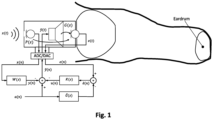
- FIG 1 shows a simplified signal flow of an exemplary hybrid ANC system which is used to explain the basics of ANC.
- An external microphone picks up the ambient noise x ( t ) and a filter W ( z ) generates the cancellation signal y ( n ).
- This feedforward system can be extended to include a feedback loop by adding an internal microphone, which picks up the error signal e ( t ) and through a filter K ( z ) generates a cancellation signal u ( n ) through a filter.
- the combination of these two approaches is called a hybrid ANC system.
- the desired audio signal or useful signal is a ( n ).
- the transmission path from external microphone to internal microphone is called the primary path P ( z ).
- the path from the loudspeaker to the internal microphone is called the secondary path G ( z ).
- the secondary path includes - in the case of a digital system - all steps from the digital output ⁇ ( n ) of the combined cancellation signal to the digital input signal e(n), i.e. in particular the digital-to-analogue conversion, the loudspeaker characteristics, the acoustic path loudspeaker-microphone, the microphone characteristics and the analogue-to-digital conversion.
- the acoustic path between the external microphone and the loudspeaker should be as large as possible in order to "gain" time for the generation of the cancellation signal y ( n ).
- the delay of the secondary path should be as small as possible.
- phase margin is important for the stability of feedback systems, i.e. the additional phase shift that is allowable before positive feedback (i.e. an unwanted amplification of a noise) occurs in the system.
- the larger the phase margin the more robust the ANC system is against external influences (e.g. changes in the transfer function), and longer filters can be used (e.g. for the noise compensation of the loudspeaker).
- the phase offset of the acoustic path loudspeaker-microphone can be easily determined for a given geometrical arrangement.
- US 2021/0281940 A1 discloses an in-ear device that comprises a transducer section, a front volume section, and a rear volume section.
- the transducer section includes a frame and piezoelectric actuators coupled to the frame.
- the piezoelectric actuators are configured to generate an acoustic pressure wave.
- the transducer section includes a first side and a second side, the second side being opposite the first side.
- the front volume section is coupled to the first side to form a front cavity, the front volume section including an aperture from which the generated acoustic pressure wave exits the front volume section towards an ear drum of a user.
- the rear volume section is coupled to the second side to form a rear cavity.
- the transducer section, the front volume section, and the rear volume section are configured to fit entirely within the ear canal.
- EP 3 739 904 A1 discloses an acoustic bending converter system comprising a plurality of bending converters configured such that deformable elements of the bending converters oscillate in a common planar layer, wherein the bending converters comprise different resonance frequencies and different expansions of the deformable elements along a common longitudinal axis that is transversal to a direction of oscillation of the deformable elements.
- the sound transducer system includes a sound generating device (as a first sound transducer) and a sound receiving device (as a second sound transducer), e.g. a microphone, wherein the sound receiving device is mounted on a surface of the housing or integrated in the housing of the sound generating device.
- the sound generating device is a chip/die, e.g. a system-on-chip or system-in-package. Conventionally, such stacking of sound transducers on each other may not be desirable due to the structure-borne sound coupling between the two transducers, and might even not be possible depending on the implementation.
- the sound generating device is a MEMS-based sound generating device, which allows avoiding or substantially reducing the structure-borne sound coupling.
- the MEMS-based sound generating device has a cavity formed between a planar cover, a planar base and circumferential sidewalls provided between the cover and the base (thereby providing an enclosure of the cavity and/or a chip housing).
- the MEMS-based sound generating device further comprises a plurality of movable actuators for generating sound. These actuators are provided in the cavity between the cover and the base. The actuators are movable in the plane between the cover and the base so that they move transverse to the direction of sound emission of the MEMS-based sound generating device.
- the actuators may be driven electrostatically, but this is only one example how the actuators can be driven.
- the cover and optionally the base have a plurality of sound outlet openings to emit sound in a direction transverse to the cover (and optionally the base).
- sound outlet openings may also be arranged in the sidewalls.
- the cover and the base have a planar structure (that extends substantially in two dimensions).
- the plane in which the actuators are movable is in parallel with the planar cover, and may be also in parallel with the planar base.
- the movement of the actuators is across the direction of the sound excitation of the sound receiving device, e.g. a microphone, structure-borne sound coupling between the cover and the sound receiving device be substantially reduced or avoided.
- the sound receiving device e.g. a microphone
- the second sound transducer is a microphone that is mounted to the cover of the MEMS-based sound generating device.
- the second sound transducer is positioned adjacent to at least one of the sound outlet openings of the cover.
- the second sound transducer may be for example positioned between two sound outlet openings of the cover. The sound is emitted through the sound outlet openings of the cover.
- the cover (and the base) may be a stiff cover (and a stiff base, respectively) to further suppress and/avoid structure-borne sound coupling between the cover and the sound receiving device.
- the one or more microphones of the sound transducer system may be used to implement ANC functionality in the sound transducer system, but the invention is not limited in this respect.
- microelectromechanical loudspeaker system implemented as a system-on-chip (SoC) or system-in-package (SiC).
- SoC system-on-chip
- SiC system-in-package
- the microelectromechanical loudspeaker system comprises a microelectromechanical sound-generating device implemented in a microelectromechanical system (MEMS).
- MEMS microelectromechanical system
- the MEMS comprises a cavity formed between a planar cover, a planar base and circumferential sidewalls provided between the cover and the base.
- the microelectromechanical loudspeaker system further comprises a microphone mounted on the cover or integrated in the cover, wherein the microphone is positioned adjacent to at least one sound outlet opening of the cover.
- the MEMS further may comprise a plurality of movable actuators for generating sound.
- the actuators may be provided in the cavity between the cover and the base.
- the cover and the base have a plurality of sound outlet openings to emit sound in a direction transverse to the cover and the base, respectively.
- the acoustic path between the microphone and the at least one adjacent sound outlet opening is less than or equal to 2 mm, and preferably less than or equal to 1 mm.
- the microelectromechanical loudspeaker system implements an active noise cancelling (ANC) function.
- the microphone is configured to detect the sound emitted through the sound outlet openings of the cover and interference noise.
- the microelectromechanical loudspeaker system further comprises a control system configured to control the sound generation of the microelectromechanical sound-generating device based on the sound detected by the microphone and interference noise such that the detected interference noise is suppressed.
- control system is configured to control sound generation of the microelectromechanical sound-generating device using an actuation signal that drives the actuators, and to receive a feedback signal from the microphone, wherein the feedback signal represents the sound emitted through the sound outlet openings of the cover and the interference noise.
- the position of the microphone on the cover is selected such that the phase difference between the (discrete) actuation signal and the (discrete) feedback signal is less than or equal to 2° to realize a cut-off frequency of at least 1 kHz, preferably 2 kHz or more and more preferably 3 kHz or more.
- the microelectromechanical sound-generating device is a multilayer silicon, germanium or silicon-germanium device.
- the cover, the base, and the actuators may be for example formed in different layers of the multilayer silicon, germanium or silicon-germanium device.
- the microphone is provided as a discrete MEMS component mounted on the cover of the microelectromechanical sound-generating device.
- the microphone may be connected to the cover of the microelectromechanical sound-generating device in an electrically conductive manner to supply a feedback signal to the control system via electrically conductive paths of the microelectromechanical sound-generating device, wherein the feedback signal represents the sound emitted through the sound outlet openings of the cover and the interference noise.
- the microphone may be formed in one or more semiconductor layers of the semiconductor device on a side of the cover facing away from the actuators.
- control system is arranged on the base and/or the cover of the microelectromechanical sound-generating device.
- the control system is connected to the microelectromechanical sound-generating device (and the microphone) in an electrically conductive manner.
- the microelectromechanical loudspeaker system further comprises a plurality of microphones positioned in the planar footprint of the microelectromechanical sound-generating device between respective adjacent sound outlet openings of the cover.
- the microphones are positioned and/or configured to detect the sound emitted through the respective sound outlet openings of the cover and any interference noise.
- the length of the acoustic path between each of the microphones and one of its adjacent sound outlet openings may be less than or equal to 2 mm and preferably less than or equal to 1 mm.
- the cavity of the microelectromechanical sound-generating device consists of multiple independent sub-cavities.
- Each of the independent sub-cavities may for example comprise one or more of the actuators for generating sound in an associated frequency band of the audible frequency spectrum which is emitted through sound outlet openings of the cover and the base provided in the planar footprint of each of the sub-cavities.
- the generating sound may also be, at least in part, outside the audible frequency spectrum.
- the microelectromechanical loudspeaker system may for example comprise multiple microphones provided on the cover or integrated in the cover of the microelectromechanical sound-generating device to detect the sound generated and emitted from the independent sub-cavities and interference noise.
- the cover has a stiffness selected to avoid structure-borne sound coupling between the cover and the microphone mounted on the cover or integrated in the cover. In some embodiments, the cover has a stiffness configured so that a sound pressure component caused by a vibration of the cover is at least 60 dB lower than the sound pressure component caused by the sound emitted through the sound outlet openings of the cover.
- the microphone comprises a membrane to receive sound emitted through the sound outlet openings of the cover and interference noise.
- the excitation of the membrane is in a direction (substantially) perpendicular to a plane defined by the planar surface of the planar cover.
- a near-field speaker may comprise a microelectromechanical loudspeaker system according to one of the various embodiments and their variations described herein.
- the cover of the microelectromechanical sound-generating device may be facing the ear or eardrum of the user of the device.
- microelectromechanical sound transducer system can be implemented as a chip/die, e.g. as a System-on-Chip (SoC) or a System-in-Package (SiP).
- SoC System-on-Chip
- SiP System-in-Package
- the microelectromechanical sound transducer system implements active noise cancellation (ANC).
- ANC active noise cancellation
- the structure-borne sound coupling between the two transducers can be avoided or substantially reduced by ensuring that the sound generation in the first sound transducer does not affect sound reception in the second sound transducer. This may be achieved, for example, by ensuring that direction of the movement of the actuators in the cavity of the sound generating transducer to produce sound pressure is across the direction in which the sound receiving device, e.g. a microphone, is excited.
- the sound receiving device measures sound pressure by the displacement of a membrane in a first direction
- the sound generation device may be designed that the sound pressure is generated by actuators moving in a plane or second direction that is (substantially) perpendicular to the first direction.
- the stiffness (i.e. the extent to which an object resists deformation in response to an applied force) of the cover of the sound generating device may also influence the level of structure-borne sound coupling between the two transducers.
- the cover (and optionally also the base) of the sound generating device may be designed to be stiff.
- "Stiff" means, in one example definition, that the sound pressure emitted from the sound generating transducer is the sound pressure generated by the movement of actuators in the cavity of the sound generating transducer, whereas sound pressure components resulting from oscillation/vibration of the cover (and the base) are neglectable.
- the cover (and base) is (are) designed in such a way that its vibration amplitude and vibration area results in a sound pressure contribution that is at least 40 dB (preferably at least 50 dB and at least 60 dB) lower than the (intended) sound pressure component caused by a sound pressure provided from the inside of the sound generating device (i.e. by the movement of the actuators in the cavity) through the openings or through holes of the cover (or base).
- the vibration amplitude of a surface i.e. the cover and the base
- vibrometry e.g. by means of laser Doppler vibrometer
- the stiffness of the cover (and base), in particular, the bending stiffness in the direction of perpendicular to the surface plane of the cover (and base), can be controlled by selecting the materials and/or geometry of the sound generating device.
- the cover and base may be a flat, planar structure that can be manufactured using conventional semiconductor manufacturing techniques.
- Sufficient stiffness can be for example realized by controlling the thickness of the cover (and base) in a thickness direction, selection of the material(s) of the cover (and base), the structuring of the cover (and base), dimensions of the enclosed cavity (or sub-cavities) in the plane perpendicular to the thickness direction, or a combination thereof.
- the sound generating device is a multilayer silicon device, where the cover, the base, and the actuators are formed in different layers of the multilayer silicon device.
- the sound generating device may also be formed as a multilayer germanium or silicon-germanium device.
- FIG. 2 An example embodiment of sound generating device is shown in Figure 2 .
- the sound generating device in Figure 2 is a micro-electromechanical system (MEMS)-based sound transducer 200 that is to emit sound.
- Figure 2 is to be considered an abstract example of the principles of a MEMS-based sound transducer that can be used to implement the embodiments according to the disclosure.
- embodiments of the invention can be implemented using MEMS-based sound transducers that are based on the technologies disclosed in PCT applications WO 2016/202790 A2 , WO 2012/095185 A1 A2, WO 2022/053165 A1 , or WO 2021/223886 A1 .
- the MEMS-based sound transducer 200 comprises a cover 201 and a base 211.
- the cover 201 faces the ear or eardrum, when the MEMS-based sound transducer 200 is used in, for example, a near-field speaker, a headphone, or as a hearing aid.
- the base 211 will be on the opposite side of that ear or eardrum.
- Cover 201 and the base 211 are flat, plane-like structures spanning mainly in the X (width) and Y (depth) direction, as indicated in Figure 2 (i.e. their dimension in the thickness direction (Z direction) is substantially smaller than that in the width and depth direction).
- the cover 201 has one or more sound outlet openings 202 from which sound pressure is emitted, as indicated by the black arrows in Figure 2 . Further example details of the cover 201 and the sound outlet openings 202 are shown in Figure 3 , which shows a cross-section of the cover 201 along the line A-A in Figure 2 .
- the sound outlet openings 202 may have an elongated shape.
- the sound outlet openings 202 may be provided (substantially) above the actuators 240 in the thickness direction.
- the sound outlet openings 202 may be shaped to follow the shape of the actuators 240 in the X direction and/or Y direction.
- the base 211 also has one or more sound outlet openings 212 from which sound pressure can be emitted in an opposite direction as also indicated by the black arrows in Figure 2 .
- the one or more sound outlet openings 212 are optional.
- the shape of the sound outlet openings 212 may be designed in a similar fashion as the shape of the sound outlet openings 202 of the cover 201.
- Cover 201 and base 211 are spaced apart (in a Y direction (thickness direction)) by sidewalls 230 and cover 201, base 211 and sidewalls 230 enclose a cavity 250.
- Figure 2 is a cross section of the MEMS-based sound transducer 200 as shown in Figure 2 along the lines B-B.
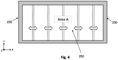
- Figure 4 when viewed in the Z direction, the lower surface of the cover at 201 towards the cavity 250 defines an area A, which has one or more sound outlet openings 202.
- sound outlet openings may also be arranged in the sidewalls 230. Sound outlet openings in the sidewalls 230 may be in addition to the sound outlet openings 202 in the cover 201. When providing sound outlet openings in the sidewalls 230, the sound is emitted transverse to the sidewalls 230, and - if present - the other sound outlet openings 202 and/or 212.
- the area A of the cover 201 that encloses the cavity 250 may be in the range from 1 mm 2 to 100 mm 2 , preferably in the range from 10 mm 2 to 40 mm 2 , and more preferably in the range from 6 mm 2 to 30 mm 2 , and even more preferably in the range from 6 mm 2 to 15 mm 2 .
- These surface area A contains the one or more sound outlet openings 202 that connect the cavity 250 of the MEMS-based sound transducer 200 with the environment for the purpose of sound output.
- the surface area of the openings 202 in the cover 201 (base 211) in comparison to the overall surface area A of the cover 201 (or base 211) is in the range from 10% to 40%.
- the MEMS-based sound transducer 200 further includes plural actuators 240.
- the actuators 24 are provided within the cavity 250 of the MEMS-based sound transducer 200.
- the sound pressure is generated by the movement of plural actuators 240 in the cavity 250 within a plane that is perpendicular to the thickness direction (Z direction).
- the actuators are indicated by the dotted lines and their movement is indicated by the white double arrows in the X direction.
- the actuators 240 can move in a plane that is perpendicular to the thickness direction in the X direction and/or Y direction.
- the sound generated by the MEMS-based sound transducer 200 may be in the audible frequency spectrum i.e. the hearing range (conventionally, 20 to 20,000 Hz) of humans.
- the MEMS-based sound transducer 200 may generate sound pressure in a frequency range that is at least in part or entirely out of the hearing range.
- the MEMS-based sound transducer 200 may emit frequencies that are entirely or at least in part outside the hearing range. This may be useful for audio-specific applications.
- One example for an audio-specific application where the frequencies may be outside the audible frequency range is the acoustic measurement of the auditory canal.
- the actuators 240 may be, for example, electrostatically driven using an actuation signal ⁇ ( t ) (see Figure 11 ).
- actuation signal ⁇ ( t ) see Figure 11
- alternative mechanisms to generate a sound pressure in the thickness direction (Z direction) could be used.
- one or more membranes (or portions thereof) that moves in X direction and/or Y direction could be used within the cavity 250 to generate a sound pressure that is emitted from the MEMS-based sound transducer 200 in the thickness direction (Z direction).
- a control system (not shown) that controls the sound generation of the MEMS-based sound transducer 200 may be provided, for example, at the bottom surface of the base 211 facing away from the cavity 250 (see Figure 2 ).
- the control system provides the actuation signal ⁇ ( t ) to control the movement of the actuators 240 within the cavity 250 of the MEMS-based sound transducer.
- the control system may be the control system 1110 that implements ANC functionality.
- the control system is mounted to the base 211.
- the MEMS-based sound transducer 200 can be provided adjacent to the control system within a SoC or SiP.
- Figure 5 shows an embodiment not encompassed by the wording of the claims but are considered as useful for understanding the invention.
- the sidewalls 530 may separate the interior space between the cover 201 and the base 211 in more than one sub-cavities 551, 552, 553.
- the lower surface of the cover at 201 towards the sub-cavities 551, 552, 553 defines respective areas A.
- Each of the sub-cavities 551, 552, 553 may include one or more actuators 240 to generate a respective sound pressure component within the respective sub-cavity.
- Each of the areas corresponding to a respective one of the sub-cavities 551, 552, 553 might include one or more sound outlet openings 202 in the cover 201, so that sound pressure can be emitted from the respective sub-cavity.
- the sub-cavities 551, 552, 553 might be associated with different frequency ranges that cover individual portions of the hearing range, so that each of the sub-cavities 551, 552, 553 generates a sound pressure component in its associated frequency range.
- this disclosure is not limited to sound generation and is not limited to the hearing range, but the MEMS-based sound transducer 200 may be configured to emit sounds at least in part or entirely in the non-audible range.
- the frequency ranges of the individual sub-cavities 551, 552, 553 might overlap.
- the sum of the sound pressure components generated in each of the sub-cavities 551, 552, 553 and emitted from the MEMS-based sound transducer 200 may advantageously cover the audible range of the spectrum.
- the areas A associated with the individual sub-cavities 551, 552, 553 may not be identical and might be different from each other. This may be useful to cover individual frequency ranges of the audible spectrum using the individual sub-cavities 551, 552, 553.
- the sum of all areas A of the cover 201 enclosing the sub-cavities 551, 552, 553 may be in the range from 1 mm 2 to 100 mm 2 , preferably in the range from 10 mm 2 to 40 mm 2 , and more preferably in the range from 6 mm 2 to 30 mm 2 , and even more preferably in the range from 6 c to 15 mm 2 .
- the MEMS-based sound transducer 200 is a multi-layer semiconductor device. In some embodiments, the MEMS-based sound transducer 200 is a multi-layer silicon device. Accordingly, in embodiments of the invention, the MEMS-based sound transducer 200 may be manufactured using (conventional) semiconductor manufacturing processes known in the art. For example, each of the (a) cover 201, (s) the sidewalls 230/530 enclosing the cavity 250/cavities 551, 552, 553 and the actuators 240, and (c) the base 211 may be implemented in one or more layers of the multilayer semiconductor device, respectively.
- the structures of the cover 201, the sidewalls 230/530, the actuators 240, and the base 211 may be formed from a semiconductor substrate by etching processes, for example reactive ion deep etching. If layers are to be bonded together, the bonding can be realized using metallic or polymeric bonding agents.
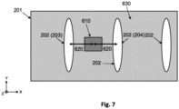
- one or more microphones 610 can be mounted on the cover 201 of the MEMS-based sound transducer 200 outlined in connection with Figures 2-5 herein above.
- the microphone 610 is mounted on the cover 201 adjacent to one of the sound outlet openings 202.
- the microphone 610 is positioned between (at least) two sound outlet openings 202 of the cover 201.
- a single microphone 610 is shown to be mounted on the surface 630 of the cover 201 facing away from the cavity 250. This is also highlighted in Figure 7 showing a view on the cover 201 of the micromechanical loudspeaker system 600 of Figure 6 in the thickness direction on the upper surface 630 of the cover 201 facing away from the cavity 250.
- additional microphones can be mounted to the upper surface 630 of the cover 201 as illustrated by the dotted rectangles in Figure 6 .
- the microphones may be distributed in the X direction and/or Y direction of the upper surface 630 of the cover 201.
- the one or more microphones 610 may be discrete components mounted on the cover 201 of the MEMS-based sound transducer 200.
- the one or more microphone 610 is a MEMS-based microphone.
- the microphone 610 cover an area in the X-Y plane of 4 mm 2 or less, preferably 1 mm 2 or less, or even 0.5 mm 2 or less.
- the microphone 610 may include a membrane 830, which is excited by the received sound pressure received by the microphone 610.
- the excitation of the membrane 830 of microphone 610 is converted into an electric signal representing the received sound pressure.
- This signal is also referred to as a feedback signal e ( t ), whereas it sampled discrete representation is the signal e ( n ) in this disclosure (see also the discussion of Figure 11 ).
- the one or more microphones 610 are mounted to the upper surface 630 of the cover 201.
- the one or more microphones 610 are mounted on the surface 630 at positions so as to not cover the sound outlet openings 202 of the cover 201 and in close proximity to the sound outlet openings 202. Mounting the one or more microphones 610 near the sound outlet openings 202 of the cover 201 of the MEMS-based sound transducer 200 facilitates substantially reducing the length of the acoustic path 620 of the sound emitted from the MEMS-based sound transducer 200.
- the microphone 610 is connected to the cover 201 of the MEMS-based sound transducer 200 in an electrically conductive manner to supply a feedback signal e(t) to the control system 1110 via electrically conductive paths.
- the electrically conductive path may be implemented in the cover 201 during the manufacturing process of the MEMS-based sound transducer 200.
- the conductive paths may connect to a control system 1110 of micromechanical loudspeaker system 600.
- intermediate layers in which the sidewalls 230/530 and actuators 240, and the base 211 of the MEMS-based sound transducer 200 are formed, may include vias and electrically conductive paths to provide for the interconnections between the control system 1110 controlling the MEMS-based sound transducer 200 and the microphone 610.
- a ball grid array could be used to interconnect the microphone 610 and respective contacts provided at the upper surface 630 of the cover 201.
- the position of the microphone 610 on the cover 201 is selected such that the phase difference between the actuation signal ⁇ ( t ) (or its discrete representation ⁇ ( n )) used to generate the sound emitted from the MEMS-based sound transducer 200 and the feedback signal e ( t ) (or its discrete representation e ( n )) representing the sound received by the microphones 610 is less than or equal to 2°. This allows realizing a cut-off frequency of at least 1 kHz
- the position of the microphone 610 on the surface 630 of the cover 201 is selected such that the phase difference of the sound signal at the point of sound reception (e.g. centroid or center of area (in X-Y plane) of the microphone 610, respectively, of its membrane 830) and the sound signal emitted at the closest point of sound emission (e.g. the centroid or center of area (in X-Y plane) of the nearest sound outlet opening 202) is less than or equal to 2° to realize a cut-off frequency of at least 1 kHz.
- the point of sound reception e.g. centroid or center of area (in X-Y plane) of the microphone 610, respectively, of its membrane 830
- the sound signal emitted at the closest point of sound emission e.g. the centroid or center of area (in X-Y plane) of the nearest sound outlet opening 202
- the distance between the centroid or center of area of microphone 610 in the X-Y plane (the plane perpendicular to the movement of the actuators 240) and the centroid (or center of area) in the X-Y plane of the nearest adjacent sound outlet opening 202 is less than or equal to 2 mm and preferably less than or equal to 1 mm.
- the positions of the microphones 610 on the cover 201 are selected such that the phase difference between the actuation signal ⁇ ( t ) (or its discrete representation ⁇ ( n )) and the feedback signal e ( t ) (or its discrete representation e ( n )) of each respective one of the microphones 610 is less than or equal to 2°.
- the length of the acoustic path 620 between each of the microphones 610 and its respective nearest adjacent sound outlet opening is less than or equal to 2 mm and preferably less than or equal to 1 mm.
- the micromechanical loudspeaker system 600 may further implement ANC functionality, as explained for example in connection with Figure 1 hereinabove or as will be explained in connection with Figure 11 below. Selecting the position of the one or more microphones 610 in the above-described manner may facilitate improving the stability of the ANC functionality provided by the micromechanical loudspeaker system 600.
- the upper cut-off frequency for conventional ANC systems may be about 1 kHz.
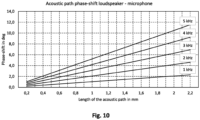
- Figure 10 illustrates the influence of the length of the acoustic path between the loudspeaker and a microphone on the phase-shift. The phase-shift is indicated for different cutoff-frequencies ranging from 1 kHz to 5 kHz and for respective lengths of the acoustic path 620.
- the acoustic path 620 should be 2 mm or less for a discrete set-up.
- the distance of the (centroid or center of area of the) microphone 610 from the (centroid or center of area of the) nearest sound outlet opening 202, 203, 204 should thus be 2 mm or less.
- the phase shift is 2° for the length of an acoustic path of 2 mm.
- the distance of the microphone 610 from the nearest sound outlet opening 202, 203, 204 should thus be 1 mm or less.
- the upper cut-off frequency is to be increased or the phase shift is to be reduced, this requires reducing the length of the acoustic path 620 between microphone 610 from the nearest sound outlet opening 202, 203, 204 while maintaining the same sound velocity.
- Figure 10 yields that doubling the cut-off frequency requires halving of the acoustic path length 620.
- realization of the acoustic path length 620 below 2 mm with discrete components is commonly problematic.
- the microphone 610 can be positioned in the immediate vicinity of the sound outlet openings 202 in the cover 201, so that the length of the acoustic path 620 can be reduced even significantly below 2 mm and even below 1 mm.
- the acoustic path length between the centroid of area of the sound outlet opening 202 and the centroid of area of the membrane 830 of the microphone 610 (in the XY plane) can be reduced to a suitable length allowing for higher cut-off frequencies of the ANC algorithm thereby contributing to the increased stability of the ANC algorithm that improves the sound quality.
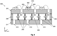
- FIG. 8 is another view of the micro mechanical loudspeaker system 600 in Figures 6 and 7 .
- the microphone has membrane 830 which is to be excited in the thickness direction (Z direction) as illustrated by the white arrow, i.e. in a direction that is perpendicular to the plane in which the actuators 240 are excited.
- the direction of excitation of the membrane 830 is perpendicular to the excitation/movement of the actuators 240 of the MEMS-based sound transducer 200.
- the excitation of the actuators 240 in the X-Y plane by a control system 1110 does not cause additional vibrations of the cover 201 in the Z direction. This can help reducing the structure-borne coupling between the MEMS-based sound transducer 200 and the microphone 610.
- the cover 201 Another factor that influences the structure-born coupling between the MEMS-based sound transducer 200 in the microphone 610 are the vibrations of the cover 201 that may be caused by the sound pressure being admitted through the sound outlet openings 202 of the cover 201 of the MEMS-based sound transducer 200. Accordingly, in some embodiments, the cover 201 (and optionally further the base 211) have sufficient stiffness (for example in terms of their bending stiffness K) to suppress those vibrations. Notably, this improvement does not necessarily require that the movement of the actuators 240 in a direction perpendicular to the direction of sound emission.
- the cover 201 (and base 211) is (are) designed in such a way that its vibration amplitude and vibration area result in a sound pressure contribution that is at least 40 dB (preferably at least 50 dB and more preferably at least 60 dB) lower than the (intended) sound pressure component caused by a sound pressure provided from the inside of the MEMS-based sound transducer 200 (i.e. by the movement of the actuators 240 in the cavity 250) through the openings or through holes 202 of the cover 201 (or base 211).
- the vibration amplitude of the surface 630 of the cover 201 yielding its sound pressure contribution can be measured, for example, using vibrometry (e.g. by means of laser Doppler vibrometer), which is an non-contact vibration measurement of the surface of the cover 201 well known in the art.
- the cover 201 (and base 211) of the sound transducer 200 may be for example made of semiconductor materials.
- Suitable semiconductor materials for the cover 201 (and the base 211) of the sound generating device may be materials that have a Young's modulus E equal to or higher than 100 GPa ( E ⁇ 100 GPa ).
- the Young's modulus E is in the range 120 GPa to 190 GPa, noting that the Young's modulus is commonly dependent on the crystal orientation.
- the cover 201 (and the base 211) could be made of silicon (Si).
- Silicon is known to have a Young's modulus in the range of 130 GPa to 189 GPa ( E ⁇ [130 GPa, 189 GPa ]), depending on the crystal orientation.
- the most relevant crystal orientations of silicon are (100), (110) and (111), where the Young's moduli are E 100 ⁇ 130 GPa, E 110 ⁇ 169 GPa and E 111 ⁇ 188 GPa.
- the cover 201 (and the base 211) could be also made of germanium (Ge), which may have a Young's modulus in the range of 103 GPa to 140 GPa.
- germanium Ge
- Another alternative material for the cover 201 (and the base 211) is silicon germanium ( Si 1- x Ge x ).
- the cover 201 (and base 211) may have a thickness in the range of 1000 ⁇ m to 100 ⁇ m , preferably in the range of 725 ⁇ m to 100 ⁇ m , more preferably in the range of 400 ⁇ m to 250 ⁇ m and even more preferably in the range of 300 ⁇ m to 200 ⁇ m.
- the one or more microphones is 610 have been mounted on a surface 630 of the cover 201 of the MEMS-based sound transducer 200.
- the microphone may be integrated within the cover 201.
- the microphone may be formed in one or more layers of the cover 201 in semiconductor manufacturing process.
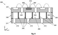
- An example embodiment where a microphone 910 is integrated in the cover 201 of the MEMS-based sound transducer 200 is shown in Figure 9.
- Figure 9 shows an alternative micromechanical loudspeaker system 900 which is similar to the micromechanical loudspeaker system 600, except for one or more microphones 910 being integrated into the cover 201.
- electrically conductive paths to connect the microphone 910 to the control system 1110 through the intermediate layers of the multilayer device forming the MEMS-based sound transducer 200 can be provided as part of the manufacturing process.
- Figure 11 shows an example embodiment of using a micromechanical loudspeaker system 600 or micromechanical loudspeaker system 900 in combination with a control system 1110 to implement ANC.
- the control system 1110 may be for example implemented using a digital signal processor (DSP), or using another programmable of non-programmable circuit.
- DSP digital signal processor
- the ANC functionality implemented in control system 1110 is substantially based on the ANC functionality described hereinabove in connection with Figure 1 .
- FIG 11 shows a simplified signal flow of an exemplary ANC system implemented in the control system 1110.
- the ANC system implemented by the control system 1110 includes a feedback loop only using the microphone 610, 910 mounted on or integrated into the MEMS-based sound transducer 200 of the micromechanical loudspeaker system 600, 900 as an internal microphone.
- the microphone 610, 910 picks up the error signal e(t), which is also referred to as a feedback signal hereinabove.
- An ADC (analog-to-digital conversion) block 1111 of the control system 1110 performs an analog-to-digital conversion by sampling the error signal e ( t ).
- the discrete error signal e ( n ) is output from the ADC block 1111.
- the discrete error signal e ( n ) is provided to an adder, which subtracts the desired audio signal or so-called “useful signal” a ( n ) from the discrete error signal e ( n ), thereby producing the error signal ⁇ ( n ), which is passed through a filter K ( z ) to generate a cancellation signal u ( n ).
- a further adder subtracts the cancellation signal u ( n ) from the desired audio signal a ( n ).
- the resultant signal is the discrete audio signal ⁇ ( n ).
- the discrete audio signal ⁇ ( n ) may be further provided to a driver circuit 1112 which generates actuation signal ⁇ ( t ) from the audio signal ⁇ ( n ).
- the actuation signal ⁇ ( t ) is used to drive the actuators 240 of the MEMS-based sound transducer 200 to cause the MEMS-based sound transducer 200 to emit sound towards the ear/eardrum of the user.
- the actuation signal ⁇ ( t ) may be used to drive of all the actuators 240 together.
- the actuation signal ⁇ ( t ) may be multiple individual actuation signals y 1 ⁇ t , y 2 ⁇ t , ... , y n ⁇ t that drive respective individual actuators 240 (e.g. n actuators) or respective groups of actuators 240 (e.g. n groups) of the MEMS-based sound transducer 200.
- This latter alternative may be for example useful to drive the one or more actuators 240 within individual sub-cavities 551, 552, 553 of the MEMS-based sound transducer 200.
- the signal path from the MEMS-based sound transducer 200 to the microphone 610, 910 is denoted the secondary path or feedback path.
- the feedback path includes all steps from the digital output ⁇ ( n ) of the combined cancellation signal to the input of the digital error signal e ( n ), i.e. the signal conversion by the driver circuit 1112 (which may include digital-to-analog conversion and amplification), the loudspeaker characteristics of the MEMS-based sound transducer 200, the acoustic path 620, the microphone characteristics of the microphone 610, 910 and analog-to-digital conversion by the ADC block 1110.
- the acoustic path 620 between the microphone 610, 910 and the MEMS-based sound transducer 200 is decreased as explained hereinabove to thereby improve the stability of the ANC functionality.
- Figure 11 illustrates a feedback-based ANC scheme
- the control system 1110 may also implement a hybrid ANC function by extending the feedback-based ANC scheme explained in connection with Figure 11 by a feedforward loop as described in connection with Figure 1 .
- another microphone may be added to the micromechanical loudspeaker system 600, 900.
- the MEMS-based sound transducer 200 may include the additional microphone on a surface of the base 211.
- the additional microphone picks up the ambient noise x ( t ).
- the control system 1110 may perform ADC conversion of the ambient noise x ( t ) (e.g. using ADC block 1111 or another ADC block) to output the discrete ambient noise signal x ( n ).
- the discrete ambient noise signal x ( n ) is further subjected to a filter W ( z ) to the generates the cancellation signal y ( n ).
- the audio signal audio signal ⁇ ( n ) is obtained by subtracting the cancellation signal u ( n ) and the cancellation signal y ( n ) from the desired signal a ( n ), as shown in Figure 1 .
- the processing of signals for implementing a feedback-based ANC function discussed in connection with Figure 11 of a hybrid ANC function may be implemented in hardware, such as programmable circuitry (e.g. field programmable gate array (FPGA), programmable logic device (PLD), etc.), in a hardened (i.e. non-programmable) circuitry (e.g. application-specific integrated circuit (ASIC), one or more digital signal processor (DSP) cores, etc.) or a hybrid combination thereof.
- the micromechanical loudspeaker system 600, 900 may be integrated in hardened circuitry.
- at least a part of the processing of the ANC algorithm may be implemented in software that is executed by the hardware (using some processing unit).
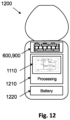
- Figure 12 illustrates an example embodiment of an in-ear headphone 1200 using a micromechanical loudspeaker system 600, 900 described herein.
- the headphone 1200 includes a micromechanical loudspeaker system 600, 900 according to one of the various embodiments described herein.
- the headphone 1200 includes a processing unit 1210.
- the processing unit 1210 may implement the control system 1110 described in connection with Figure 11 to implement ANC in the headphone 1200.
- the some of functionality of control system 1110 e.g. the functionality of the adders and filters
- the headphone 1200 may include a battery 1222 power the processing unit 1210 and any other components requiring power within the headphone 1200.
- the headphone 1200 may further include components that facilitate Bluetooth connectivity to external devices (for example a mobile phone, laptop, tablet computer, etc.) to provide an audio source to be output by the headphone 1200.
- components of the headphone 1200 may provide Wi-Fi connectivity or cellular connectivity (e.g. according to 3GPP standards) for this purpose.
- the headphone 1200 can include components facilitating wired or wireless charging of the battery.
- the headphone 1200 could a USB connector for charging and/or communication of data with an external device.
Landscapes
- Engineering & Computer Science (AREA)
- Physics & Mathematics (AREA)
- Acoustics & Sound (AREA)
- Signal Processing (AREA)
- Multimedia (AREA)
- Manufacturing & Machinery (AREA)
- Soundproofing, Sound Blocking, And Sound Damping (AREA)
Claims (15)
- Mikroelektromechanisches Lautsprechersystem, das als ein System-on-Chip oder System-in-Package implementiert ist, umfassend:eine mikroelektromechanische Schallerzeugungsvorrichtung, die in einem mikroelektromechanischen System, MEMS, implementiert ist, wobei das MEMS einen Hohlraum (250, 551-553) umfasst, der zwischen einer planaren Abdeckung, einer planaren Basis und umlaufenden Seitenwänden, die zwischen der Abdeckung (201) und der Basis (211) bereitgestellt sind, gebildet ist,wobei das MEMS ferner eine Mehrzahl von beweglichen Aktuatoren zum Erzeugen von Schall umfasst, wobei die Aktuatoren (24, 240) in dem Hohlraum (250, 551-553) zwischen der Abdeckung (201) und der Basis (211) bereitgestellt sind und die Aktuatoren (24, 240) in einer Ebene beweglich sind, die quer zu einer Richtung der Schallübertragung der mikroelektromechanischen Schallerzeugungsvorrichtung ist, und wobei die Abdeckung (201) eine Mehrzahl von Schallauslassöffnungen (202-204, 212) umfasst, um Schall in der Richtung der Schallübertragung zu emittieren, die quer zu der Abdeckung (201) ist;ein Mikrofon (610, 910), das an der Abdeckung (201) montiert oder in die Abdeckung (201) integriert ist, wobei das Mikrofon (610, 910) zu mindestens einer Schallauslassöffnung der Abdeckung (201) benachbart positioniert ist.
- Mikroelektromechanisches Lautsprechersystem nach Anspruch 1, wobei der akustische Pfad zwischen dem Mikrofon und der mindestens einen benachbarten Schallauslassöffnung kleiner als oder gleich 2 mm und vorzugsweise kleiner als oder gleich 1 mm ist.
- Mikroelektromechanisches Lautsprechersystem nach Anspruch 1 oder 2, wobei das mikroelektromechanische Lautsprechersystem eine aktive Rauschunterdrückungsfunktion, ANC-Funktion, implementiert,wobei das Mikrofon konfiguriert ist, um den Schall, der durch die Schallauslassöffnungen der Abdeckung emittiert wird, und Interferenzrauschen zu detektieren; unddas mikroelektromechanische Lautsprechersystem ferner ein Steuersystem umfasst, das konfiguriert ist, die Schallerzeugung der mikroelektromechanischen Schallerzeugungsvorrichtung basierend auf dem Schall, der durch das Mikrofon detektiert wird, und Interferenzrauschen zu steuern, sodass das detektierte Interferenzrauschen unterdrückt wird;wobei das Steuersystem konfiguriert ist, die Schallerzeugung der mikroelektromechanischen Schallerzeugungsvorrichtung unter Verwendung eines Betätigungssignals zu steuern, das die Aktuatoren antreibt, und ein Rückkopplungssignal von dem Mikrofon zu empfangen, wobei das Rückkopplungssignal den Schall, der durch die Schallauslassöffnungen der Abdeckung emittiert wird, und das Interferenzrauschen darstellt.
- Mikroelektromechanisches Lautsprechersystem nach Anspruch 3, wobei das Steuersystem auf der Basis und/oder der Abdeckung der mikroelektromechanischen Schallerzeugungsvorrichtung angeordnet ist und mit der mikroelektromechanischen Schallerzeugungsvorrichtung auf eine elektrisch leitende Weise verbunden ist.
- Mikroelektromechanisches Lautsprechersystem nach einem der Ansprüche 1 bis 4, wobei die Position des Mikrofons auf der Abdeckung derart ausgewählt ist, dass die Phasendifferenz zwischen dem Betätigungssignal und dem Rückkopplungssignal kleiner als oder gleich 2° ist, um eine Grenzfrequenz von mindestens 1 kHz, vorzugsweise 2 kHz oder mehr und mehr bevorzugt 3 kHz oder mehr zu realisieren.
- Mikroelektromechanisches Lautsprechersystem nach einem der Ansprüche 1 bis 5, wobei die mikroelektromechanische Schallerzeugungsvorrichtung eine mehrschichtige Siliziumvorrichtung ist;
wobei die Abdeckung, die Basis und die Aktuatoren in verschiedenen Schichten der mehrschichtigen Siliziumvorrichtung gebildet sind. - Mikroelektromechanisches Lautsprechersystem nach Anspruch 6, wobei das Mikrofon in einer oder mehreren Halbleiterschichten der Halbleitervorrichtung auf einer Seite der Abdeckung gebildet ist, die von den Aktuatoren abgewandt ist.
- Mikroelektromechanisches Lautsprechersystem nach einem der Ansprüche 1 bis 6, wobei das Mikrofon eine diskrete MEMS-basierte Komponente ist, die an der Abdeckung der mikroelektromechanischen Schallerzeugungsvorrichtung montiert ist.
- Mikroelektromechanisches Lautsprechersystem nach Anspruch 3 oder 4, wobei das Mikrofon eine diskrete MEMS-basierte Komponente ist, die an der Abdeckung der mikroelektromechanischen Schallerzeugungsvorrichtung befestigt ist; und
wobei das Mikrofon mit der Abdeckung der mikroelektromechanischen Schallerzeugungsvorrichtung auf eine elektrisch leitende Weise verbunden ist, um dem Steuersystem über elektrisch leitende Pfade der mikroelektromechanischen Schallerzeugungsvorrichtung ein Rückkopplungssignal zuzuführen, wobei das Rückkopplungssignal den Schall, der durch die Schallauslassöffnungen der Abdeckung emittiert wird, und das Interferenzrauschen darstellt. - Mikroelektromechanisches Lautsprechersystem nach einem der Ansprüche 1 bis 9, wobei das mikroelektromechanische Lautsprechersystem eine Mehrzahl von Mikrofonen umfasst, die in der planaren Grundfläche der mikroelektromechanischen Schallerzeugungsvorrichtung zwischen jeweiligen benachbarten Schallauslassöffnungen der Abdeckung positioniert sind,wobei die Mikrofone konfiguriert sind, um den Schall, der durch die jeweiligen Schallauslassöffnungen der Abdeckung emittiert wird, und jegliches Interferenzrauschen zu detektieren;wobei der akustische Pfad zwischen jedem der Mikrofone und einer seiner benachbarten Schallauslassöffnungen kleiner als oder gleich 2 mm und vorzugsweise kleiner als oder gleich 1 mm ist.
- Mikroelektromechanisches Lautsprechersystem nach einem der Ansprüche 1 bis 10, wobei der Hohlraum der mikroelektromechanischen Schallerzeugungsvorrichtung aus mehreren unabhängigen Sub-Hohlräumen besteht,wobei jeder der unabhängigen Sub-Hohlräume einen oder mehrere der Aktuatoren zum Erzeugen von Schall in einem zugeordneten Frequenzband des hörbaren Frequenzspektrums umfasst, der durch Schallauslassöffnungen der Abdeckung und der Basis emittiert wird, die in der planaren Grundfläche jedes der Sub-Hohlräume bereitgestellt sind;wobei das mikroelektromechanische Lautsprechersystem mehrere Mikrofone umfasst, die an der Abdeckung bereitgestellt oder in die Abdeckung der mikroelektromechanischen Schallerzeugungsvorrichtung integriert sind, um den Schall, der von jedem der unabhängigen Sub-Hohlräume erzeugt und emittiert wird, und Interferenzrauschen zu detektieren.
- Mikroelektromechanisches Lautsprechersystem nach einem der Ansprüche 1 bis 11, wobei die Abdeckung eine Steifigkeit aufweist, die so gewählt ist, um eine Körperschallkopplung zwischen der Abdeckung und dem Mikrofon, das an der Abdeckung montiert oder in die Abdeckung integriert ist, zu vermeiden.
- Mikroelektromechanisches Lautsprechersystem nach einem der Ansprüche 1 bis 12, wobei die Abdeckung eine Steifigkeit aufweist, die so konfiguriert ist, dass eine Schalldruckkomponente, die durch eine Vibration der Abdeckung verursacht wird, mindestens 60 dB niedriger als die Schalldruckkomponente ist, die durch den Schall verursacht wird, der durch die Schallauslassöffnungen der Abdeckung emittiert wird.
- Mikroelektromechanisches Lautsprechersystem nach einem der Ansprüche 1 bis 13, wobei das Mikrofon eine Membran umfasst, um Schall, der durch die Schallauslassöffnungen der Abdeckung emittiert wird, und Interferenzrauschen zu empfangen, wobei die Membran in einer Richtung angeregt wird, die im Wesentlichen senkrecht zu einer Ebene ist, die durch die planare Oberfläche der planaren Abdeckung definiert ist.
- Vorrichtung mit einem mikroelektromechanischen Lautsprechersystem nach einem der Ansprüche 1 bis 14, wobei die Vorrichtung als ein Nahfeldlautsprecher, ein Kopfhörer (1200) oder als ein Hörgerät ausgelegt ist.
Priority Applications (3)
| Application Number | Priority Date | Filing Date | Title |
|---|---|---|---|
| EP21198862.1A EP4156712B1 (de) | 2021-09-24 | 2021-09-24 | Mikroelektromechanisches lautsprechersystem |
| US17/887,242 US12114130B2 (en) | 2021-09-24 | 2022-08-12 | Microelectromechanical sound transducer system |
| CN202210973810.XA CN115955642A (zh) | 2021-09-24 | 2022-08-15 | 微机电声音换能器系统 |
Applications Claiming Priority (1)
| Application Number | Priority Date | Filing Date | Title |
|---|---|---|---|
| EP21198862.1A EP4156712B1 (de) | 2021-09-24 | 2021-09-24 | Mikroelektromechanisches lautsprechersystem |
Publications (2)
| Publication Number | Publication Date |
|---|---|
| EP4156712A1 EP4156712A1 (de) | 2023-03-29 |
| EP4156712B1 true EP4156712B1 (de) | 2024-08-21 |
Family
ID=77951541
Family Applications (1)
| Application Number | Title | Priority Date | Filing Date |
|---|---|---|---|
| EP21198862.1A Active EP4156712B1 (de) | 2021-09-24 | 2021-09-24 | Mikroelektromechanisches lautsprechersystem |
Country Status (3)
| Country | Link |
|---|---|
| US (1) | US12114130B2 (de) |
| EP (1) | EP4156712B1 (de) |
| CN (1) | CN115955642A (de) |
Families Citing this family (3)
| Publication number | Priority date | Publication date | Assignee | Title |
|---|---|---|---|---|
| US20240339099A1 (en) * | 2023-04-06 | 2024-10-10 | Knowles Electronics, Llc | Low Latency Audio Processing System Having Active Noise Cancellation for Ear-Worn Hearing Device |
| DE102023203207A1 (de) | 2023-04-06 | 2024-10-10 | Robert Bosch Gesellschaft mit beschränkter Haftung | Mikrofluidisches Bauelement zum Interagieren mit einem Volumenstrom eines Fluids sowie eine Vorrichtung mit einem solchen mikrofluidischen Bauelement sowie ein Herstellungsverfahren für ein mikrofluidisches Bauelement |
| DE102023204072A1 (de) * | 2023-05-03 | 2024-11-07 | Robert Bosch Gesellschaft mit beschränkter Haftung | Mikroelektromechanisches Bauelement |
Family Cites Families (13)
| Publication number | Priority date | Publication date | Assignee | Title |
|---|---|---|---|---|
| US5182774A (en) * | 1990-07-20 | 1993-01-26 | Telex Communications, Inc. | Noise cancellation headset |
| JP5951640B2 (ja) | 2011-01-14 | 2016-07-13 | フラウンホッファー−ゲゼルシャフト ツァ フェルダールング デァ アンゲヴァンテン フォアシュンク エー.ファオ | マイクロメカニカルデバイス |
| US9738515B2 (en) * | 2012-06-27 | 2017-08-22 | Invensense, Inc. | Transducer with enlarged back volume |
| DE102015210919A1 (de) | 2015-06-15 | 2016-12-15 | Fraunhofer-Gesellschaft zur Förderung der angewandten Forschung e.V. | MEMS-Wandler zum Interagieren mit einem Volumenstrom eines Fluids und Verfahren zum Herstellen desselben |
| US11368782B2 (en) * | 2016-02-08 | 2022-06-21 | Light Speed Aviation, Inc. | System and method for converting passive protectors to ANR headphones or communication headsets |
| GB2538432B (en) * | 2016-08-05 | 2017-08-30 | Incus Laboratories Ltd | Acoustic coupling arrangements for noise-cancelling headphones and earphones |
| DE102017105594A1 (de) | 2017-03-16 | 2018-09-20 | USound GmbH | Verstärkereinheit für einen Schallwandler und Schallerzeugungseinheit |
| EP4300995A3 (de) * | 2018-12-19 | 2024-04-03 | Sonion Nederland B.V. | Miniaturlautsprecher mit mehreren schallhohlräumen |
| EP3739904B1 (de) | 2019-05-14 | 2024-10-16 | Fraunhofer-Gesellschaft zur Förderung der angewandten Forschung e.V. | Akustisches biegewandlersystem und akustische vorrichtung |
| US11202138B2 (en) * | 2020-03-05 | 2021-12-14 | Facebook Technologies, Llc | Miniature high performance MEMS piezoelectric transducer for in-ear applications |
| JP2023525730A (ja) | 2020-05-08 | 2023-06-19 | フラウンホーファー-ゲゼルシャフト・ツール・フェルデルング・デル・アンゲヴァンテン・フォルシュング・アインゲトラーゲネル・フェライン | 体積流との高効率な相互作用のためのmems |
| DE112020007605A5 (de) | 2020-09-14 | 2023-06-29 | Arioso Systems Gmbh | Mems-bauelement, hearable, mems-pumpe, lautsprecher und verfahren zum ansteuern eines mems-bauelements |
| EP4255844A1 (de) * | 2020-12-03 | 2023-10-11 | Fraunhofer-Gesellschaft zur Förderung der angewandten Forschung e.V. | Mems mit deckelantrieb und verfahren zum betreiben derselben |
-
2021
- 2021-09-24 EP EP21198862.1A patent/EP4156712B1/de active Active
-
2022
- 2022-08-12 US US17/887,242 patent/US12114130B2/en active Active
- 2022-08-15 CN CN202210973810.XA patent/CN115955642A/zh active Pending
Also Published As
| Publication number | Publication date |
|---|---|
| US20230101608A1 (en) | 2023-03-30 |
| US12114130B2 (en) | 2024-10-08 |
| EP4156712A1 (de) | 2023-03-29 |
| CN115955642A (zh) | 2023-04-11 |
Similar Documents
| Publication | Publication Date | Title |
|---|---|---|
| US12114130B2 (en) | Microelectromechanical sound transducer system | |
| JP5691181B2 (ja) | マイクロホンユニット、及び、それを備えた音声入力装置 | |
| JP5834383B2 (ja) | マイクロホンユニット及びそれを備えた音声入力装置 | |
| JP5200737B2 (ja) | 差動マイクロホンユニット | |
| US20140233756A1 (en) | Sound input device | |
| US8649545B2 (en) | Microphone unit | |
| US20140226836A1 (en) | Voice input device and noise suppression method | |
| KR101612851B1 (ko) | 초소형 보청기 | |
| WO2010013602A1 (ja) | 差動マイクロホン | |
| US12185055B2 (en) | Multi-cavity packaging for microelectromechanical system microphones | |
| WO2022100551A1 (zh) | Mems压电微扬声器、微扬声器单元及电子设备 | |
| KR20110030418A (ko) | 마이크로폰 유닛, 근거리 대화식 음성 입력 장치, 정보 처리 시스템, 및 마이크로폰 유닛의 제조 방법 | |
| KR20090053721A (ko) | 마이크로폰 시스템, 소리 입력 장치 및 그 제조 방법 | |
| KR101833892B1 (ko) | 압전 멤스 기반 초지향성 라우드 스피커 및 이의 빔 조향 방법 | |
| JP7171156B1 (ja) | Memsスピーカ及びスピーカの取付構造 | |
| CN117319906A (zh) | 一种扬声器模组、电子设备、mems扬声器及其制作方法 | |
| JP2006100954A (ja) | 圧電型音響変換装置およびその製造方法 | |
| CN218450447U (zh) | 麦克风和扬声器组合模组、耳机及电子设备 | |
| JP2025522417A (ja) | 統合型mems静電マイクロスピーカー | |
| JP2014075671A (ja) | 音響デバイス及びそれを用いた電子機器 | |
| JP5419254B2 (ja) | マイクロホンユニット | |
| CN113259820A (zh) | 麦克风 | |
| KR102726900B1 (ko) | 자동차용 고감도 일체형 노이즈 캔슬링 마이크로폰 소자 | |
| JP2007081706A (ja) | コンデンサマイクロホン | |
| US20250008249A1 (en) | Speaker unit and earpiece |
Legal Events
| Date | Code | Title | Description |
|---|---|---|---|
| PUAI | Public reference made under article 153(3) epc to a published international application that has entered the european phase |
Free format text: ORIGINAL CODE: 0009012 |
|
| STAA | Information on the status of an ep patent application or granted ep patent |
Free format text: STATUS: REQUEST FOR EXAMINATION WAS MADE |
|
| 17P | Request for examination filed |
Effective date: 20220728 |
|
| AK | Designated contracting states |
Kind code of ref document: A1 Designated state(s): AL AT BE BG CH CY CZ DE DK EE ES FI FR GB GR HR HU IE IS IT LI LT LU LV MC MK MT NL NO PL PT RO RS SE SI SK SM TR |
|
| RIN1 | Information on inventor provided before grant (corrected) |
Inventor name: KOCH, TILMANN Inventor name: EHRIG, LUTZ |
|
| GRAP | Despatch of communication of intention to grant a patent |
Free format text: ORIGINAL CODE: EPIDOSNIGR1 |
|
| STAA | Information on the status of an ep patent application or granted ep patent |
Free format text: STATUS: GRANT OF PATENT IS INTENDED |
|
| INTG | Intention to grant announced |
Effective date: 20230530 |
|
| GRAJ | Information related to disapproval of communication of intention to grant by the applicant or resumption of examination proceedings by the epo deleted |
Free format text: ORIGINAL CODE: EPIDOSDIGR1 |
|
| STAA | Information on the status of an ep patent application or granted ep patent |
Free format text: STATUS: REQUEST FOR EXAMINATION WAS MADE |
|
| GRAP | Despatch of communication of intention to grant a patent |
Free format text: ORIGINAL CODE: EPIDOSNIGR1 |
|
| STAA | Information on the status of an ep patent application or granted ep patent |
Free format text: STATUS: GRANT OF PATENT IS INTENDED |
|
| INTC | Intention to grant announced (deleted) | ||
| INTG | Intention to grant announced |
Effective date: 20231013 |
|
| GRAJ | Information related to disapproval of communication of intention to grant by the applicant or resumption of examination proceedings by the epo deleted |
Free format text: ORIGINAL CODE: EPIDOSDIGR1 |
|
| GRAP | Despatch of communication of intention to grant a patent |
Free format text: ORIGINAL CODE: EPIDOSNIGR1 |
|
| INTG | Intention to grant announced |
Effective date: 20240322 |
|
| GRAS | Grant fee paid |
Free format text: ORIGINAL CODE: EPIDOSNIGR3 |
|
| GRAA | (expected) grant |
Free format text: ORIGINAL CODE: 0009210 |
|
| STAA | Information on the status of an ep patent application or granted ep patent |
Free format text: STATUS: THE PATENT HAS BEEN GRANTED |
|
| AK | Designated contracting states |
Kind code of ref document: B1 Designated state(s): AL AT BE BG CH CY CZ DE DK EE ES FI FR GB GR HR HU IE IS IT LI LT LU LV MC MK MT NL NO PL PT RO RS SE SI SK SM TR |
|
| P01 | Opt-out of the competence of the unified patent court (upc) registered |
Free format text: CASE NUMBER: APP_41048/2024 Effective date: 20240711 |
|
| REG | Reference to a national code |
Ref country code: GB Ref legal event code: FG4D |
|
| REG | Reference to a national code |
Ref country code: CH Ref legal event code: EP |
|
| REG | Reference to a national code |
Ref country code: IE Ref legal event code: FG4D |
|
| REG | Reference to a national code |
Ref country code: DE Ref legal event code: R096 Ref document number: 602021017441 Country of ref document: DE |
|
| REG | Reference to a national code |
Ref country code: LT Ref legal event code: MG9D |
|
| REG | Reference to a national code |
Ref country code: NL Ref legal event code: MP Effective date: 20240821 |
|
| PG25 | Lapsed in a contracting state [announced via postgrant information from national office to epo] |
Ref country code: NO Free format text: LAPSE BECAUSE OF FAILURE TO SUBMIT A TRANSLATION OF THE DESCRIPTION OR TO PAY THE FEE WITHIN THE PRESCRIBED TIME-LIMIT Effective date: 20241121 |
|
| REG | Reference to a national code |
Ref country code: AT Ref legal event code: MK05 Ref document number: 1716754 Country of ref document: AT Kind code of ref document: T Effective date: 20240821 |
|
| PG25 | Lapsed in a contracting state [announced via postgrant information from national office to epo] |
Ref country code: NL Free format text: LAPSE BECAUSE OF FAILURE TO SUBMIT A TRANSLATION OF THE DESCRIPTION OR TO PAY THE FEE WITHIN THE PRESCRIBED TIME-LIMIT Effective date: 20240821 Ref country code: FI Free format text: LAPSE BECAUSE OF FAILURE TO SUBMIT A TRANSLATION OF THE DESCRIPTION OR TO PAY THE FEE WITHIN THE PRESCRIBED TIME-LIMIT Effective date: 20240821 Ref country code: GR Free format text: LAPSE BECAUSE OF FAILURE TO SUBMIT A TRANSLATION OF THE DESCRIPTION OR TO PAY THE FEE WITHIN THE PRESCRIBED TIME-LIMIT Effective date: 20241122 Ref country code: PT Free format text: LAPSE BECAUSE OF FAILURE TO SUBMIT A TRANSLATION OF THE DESCRIPTION OR TO PAY THE FEE WITHIN THE PRESCRIBED TIME-LIMIT Effective date: 20241223 Ref country code: PL Free format text: LAPSE BECAUSE OF FAILURE TO SUBMIT A TRANSLATION OF THE DESCRIPTION OR TO PAY THE FEE WITHIN THE PRESCRIBED TIME-LIMIT Effective date: 20240821 |
|
| PG25 | Lapsed in a contracting state [announced via postgrant information from national office to epo] |
Ref country code: BG Free format text: LAPSE BECAUSE OF FAILURE TO SUBMIT A TRANSLATION OF THE DESCRIPTION OR TO PAY THE FEE WITHIN THE PRESCRIBED TIME-LIMIT Effective date: 20240821 |
|
| PG25 | Lapsed in a contracting state [announced via postgrant information from national office to epo] |
Ref country code: LV Free format text: LAPSE BECAUSE OF FAILURE TO SUBMIT A TRANSLATION OF THE DESCRIPTION OR TO PAY THE FEE WITHIN THE PRESCRIBED TIME-LIMIT Effective date: 20240821 |
|
| PG25 | Lapsed in a contracting state [announced via postgrant information from national office to epo] |
Ref country code: AT Free format text: LAPSE BECAUSE OF FAILURE TO SUBMIT A TRANSLATION OF THE DESCRIPTION OR TO PAY THE FEE WITHIN THE PRESCRIBED TIME-LIMIT Effective date: 20240821 Ref country code: IS Free format text: LAPSE BECAUSE OF FAILURE TO SUBMIT A TRANSLATION OF THE DESCRIPTION OR TO PAY THE FEE WITHIN THE PRESCRIBED TIME-LIMIT Effective date: 20241221 |
|
| PG25 | Lapsed in a contracting state [announced via postgrant information from national office to epo] |
Ref country code: HR Free format text: LAPSE BECAUSE OF FAILURE TO SUBMIT A TRANSLATION OF THE DESCRIPTION OR TO PAY THE FEE WITHIN THE PRESCRIBED TIME-LIMIT Effective date: 20240821 |
|
| PG25 | Lapsed in a contracting state [announced via postgrant information from national office to epo] |
Ref country code: RS Free format text: LAPSE BECAUSE OF FAILURE TO SUBMIT A TRANSLATION OF THE DESCRIPTION OR TO PAY THE FEE WITHIN THE PRESCRIBED TIME-LIMIT Effective date: 20241121 Ref country code: ES Free format text: LAPSE BECAUSE OF FAILURE TO SUBMIT A TRANSLATION OF THE DESCRIPTION OR TO PAY THE FEE WITHIN THE PRESCRIBED TIME-LIMIT Effective date: 20240821 |
|
| PG25 | Lapsed in a contracting state [announced via postgrant information from national office to epo] |
Ref country code: RS Free format text: LAPSE BECAUSE OF FAILURE TO SUBMIT A TRANSLATION OF THE DESCRIPTION OR TO PAY THE FEE WITHIN THE PRESCRIBED TIME-LIMIT Effective date: 20241121 Ref country code: PT Free format text: LAPSE BECAUSE OF FAILURE TO SUBMIT A TRANSLATION OF THE DESCRIPTION OR TO PAY THE FEE WITHIN THE PRESCRIBED TIME-LIMIT Effective date: 20241223 Ref country code: PL Free format text: LAPSE BECAUSE OF FAILURE TO SUBMIT A TRANSLATION OF THE DESCRIPTION OR TO PAY THE FEE WITHIN THE PRESCRIBED TIME-LIMIT Effective date: 20240821 Ref country code: NO Free format text: LAPSE BECAUSE OF FAILURE TO SUBMIT A TRANSLATION OF THE DESCRIPTION OR TO PAY THE FEE WITHIN THE PRESCRIBED TIME-LIMIT Effective date: 20241121 Ref country code: NL Free format text: LAPSE BECAUSE OF FAILURE TO SUBMIT A TRANSLATION OF THE DESCRIPTION OR TO PAY THE FEE WITHIN THE PRESCRIBED TIME-LIMIT Effective date: 20240821 Ref country code: LV Free format text: LAPSE BECAUSE OF FAILURE TO SUBMIT A TRANSLATION OF THE DESCRIPTION OR TO PAY THE FEE WITHIN THE PRESCRIBED TIME-LIMIT Effective date: 20240821 Ref country code: IS Free format text: LAPSE BECAUSE OF FAILURE TO SUBMIT A TRANSLATION OF THE DESCRIPTION OR TO PAY THE FEE WITHIN THE PRESCRIBED TIME-LIMIT Effective date: 20241221 Ref country code: HR Free format text: LAPSE BECAUSE OF FAILURE TO SUBMIT A TRANSLATION OF THE DESCRIPTION OR TO PAY THE FEE WITHIN THE PRESCRIBED TIME-LIMIT Effective date: 20240821 Ref country code: GR Free format text: LAPSE BECAUSE OF FAILURE TO SUBMIT A TRANSLATION OF THE DESCRIPTION OR TO PAY THE FEE WITHIN THE PRESCRIBED TIME-LIMIT Effective date: 20241122 Ref country code: FI Free format text: LAPSE BECAUSE OF FAILURE TO SUBMIT A TRANSLATION OF THE DESCRIPTION OR TO PAY THE FEE WITHIN THE PRESCRIBED TIME-LIMIT Effective date: 20240821 Ref country code: ES Free format text: LAPSE BECAUSE OF FAILURE TO SUBMIT A TRANSLATION OF THE DESCRIPTION OR TO PAY THE FEE WITHIN THE PRESCRIBED TIME-LIMIT Effective date: 20240821 Ref country code: BG Free format text: LAPSE BECAUSE OF FAILURE TO SUBMIT A TRANSLATION OF THE DESCRIPTION OR TO PAY THE FEE WITHIN THE PRESCRIBED TIME-LIMIT Effective date: 20240821 Ref country code: AT Free format text: LAPSE BECAUSE OF FAILURE TO SUBMIT A TRANSLATION OF THE DESCRIPTION OR TO PAY THE FEE WITHIN THE PRESCRIBED TIME-LIMIT Effective date: 20240821 |
|
| PG25 | Lapsed in a contracting state [announced via postgrant information from national office to epo] |
Ref country code: SM Free format text: LAPSE BECAUSE OF FAILURE TO SUBMIT A TRANSLATION OF THE DESCRIPTION OR TO PAY THE FEE WITHIN THE PRESCRIBED TIME-LIMIT Effective date: 20240821 Ref country code: RO Free format text: LAPSE BECAUSE OF FAILURE TO SUBMIT A TRANSLATION OF THE DESCRIPTION OR TO PAY THE FEE WITHIN THE PRESCRIBED TIME-LIMIT Effective date: 20240821 Ref country code: DK Free format text: LAPSE BECAUSE OF FAILURE TO SUBMIT A TRANSLATION OF THE DESCRIPTION OR TO PAY THE FEE WITHIN THE PRESCRIBED TIME-LIMIT Effective date: 20240821 |
|
| PG25 | Lapsed in a contracting state [announced via postgrant information from national office to epo] |
Ref country code: EE Free format text: LAPSE BECAUSE OF FAILURE TO SUBMIT A TRANSLATION OF THE DESCRIPTION OR TO PAY THE FEE WITHIN THE PRESCRIBED TIME-LIMIT Effective date: 20240821 |
|
| PG25 | Lapsed in a contracting state [announced via postgrant information from national office to epo] |
Ref country code: CZ Free format text: LAPSE BECAUSE OF FAILURE TO SUBMIT A TRANSLATION OF THE DESCRIPTION OR TO PAY THE FEE WITHIN THE PRESCRIBED TIME-LIMIT Effective date: 20240821 |
|
| PG25 | Lapsed in a contracting state [announced via postgrant information from national office to epo] |
Ref country code: IT Free format text: LAPSE BECAUSE OF FAILURE TO SUBMIT A TRANSLATION OF THE DESCRIPTION OR TO PAY THE FEE WITHIN THE PRESCRIBED TIME-LIMIT Effective date: 20240821 Ref country code: SK Free format text: LAPSE BECAUSE OF FAILURE TO SUBMIT A TRANSLATION OF THE DESCRIPTION OR TO PAY THE FEE WITHIN THE PRESCRIBED TIME-LIMIT Effective date: 20240821 |
|
| REG | Reference to a national code |
Ref country code: CH Ref legal event code: PL |
|
| PG25 | Lapsed in a contracting state [announced via postgrant information from national office to epo] |
Ref country code: LU Free format text: LAPSE BECAUSE OF NON-PAYMENT OF DUE FEES Effective date: 20240924 |
|
| REG | Reference to a national code |
Ref country code: DE Ref legal event code: R097 Ref document number: 602021017441 Country of ref document: DE |
|
| PLBE | No opposition filed within time limit |
Free format text: ORIGINAL CODE: 0009261 |
|
| STAA | Information on the status of an ep patent application or granted ep patent |
Free format text: STATUS: NO OPPOSITION FILED WITHIN TIME LIMIT |
|
| PG25 | Lapsed in a contracting state [announced via postgrant information from national office to epo] |
Ref country code: MC Free format text: LAPSE BECAUSE OF FAILURE TO SUBMIT A TRANSLATION OF THE DESCRIPTION OR TO PAY THE FEE WITHIN THE PRESCRIBED TIME-LIMIT Effective date: 20240821 |
|
| REG | Reference to a national code |
Ref country code: BE Ref legal event code: MM Effective date: 20240930 |
|
| PG25 | Lapsed in a contracting state [announced via postgrant information from national office to epo] |
Ref country code: BE Free format text: LAPSE BECAUSE OF NON-PAYMENT OF DUE FEES Effective date: 20240930 |
|
| PG25 | Lapsed in a contracting state [announced via postgrant information from national office to epo] |
Ref country code: FR Free format text: LAPSE BECAUSE OF NON-PAYMENT OF DUE FEES Effective date: 20241021 |
|
| PG25 | Lapsed in a contracting state [announced via postgrant information from national office to epo] |
Ref country code: CH Free format text: LAPSE BECAUSE OF NON-PAYMENT OF DUE FEES Effective date: 20240930 |
|
| PG25 | Lapsed in a contracting state [announced via postgrant information from national office to epo] |
Ref country code: IE Free format text: LAPSE BECAUSE OF NON-PAYMENT OF DUE FEES Effective date: 20240924 |
|
| 26N | No opposition filed |
Effective date: 20250522 |
|
| PG25 | Lapsed in a contracting state [announced via postgrant information from national office to epo] |
Ref country code: SE Free format text: LAPSE BECAUSE OF FAILURE TO SUBMIT A TRANSLATION OF THE DESCRIPTION OR TO PAY THE FEE WITHIN THE PRESCRIBED TIME-LIMIT Effective date: 20240821 |
|
| PGFP | Annual fee paid to national office [announced via postgrant information from national office to epo] |
Ref country code: DE Payment date: 20250926 Year of fee payment: 5 |
|
| PG25 | Lapsed in a contracting state [announced via postgrant information from national office to epo] |
Ref country code: CY Free format text: LAPSE BECAUSE OF FAILURE TO SUBMIT A TRANSLATION OF THE DESCRIPTION OR TO PAY THE FEE WITHIN THE PRESCRIBED TIME-LIMIT; INVALID AB INITIO Effective date: 20210924 |