EP4156438B1 - Stromverteilungssystem für eine heimanlage mit mehreren stromquellen - Google Patents
Stromverteilungssystem für eine heimanlage mit mehreren stromquellen Download PDFInfo
- Publication number
- EP4156438B1 EP4156438B1 EP22305033.7A EP22305033A EP4156438B1 EP 4156438 B1 EP4156438 B1 EP 4156438B1 EP 22305033 A EP22305033 A EP 22305033A EP 4156438 B1 EP4156438 B1 EP 4156438B1
- Authority
- EP
- European Patent Office
- Prior art keywords
- electrical
- phase
- connection device
- conduction path
- loads
- Prior art date
- Legal status (The legal status is an assumption and is not a legal conclusion. Google has not performed a legal analysis and makes no representation as to the accuracy of the status listed.)
- Active
Links
Images


Classifications
-
- H—ELECTRICITY
- H02—GENERATION; CONVERSION OR DISTRIBUTION OF ELECTRIC POWER
- H02J—ELECTRIC POWER NETWORKS; CIRCUIT ARRANGEMENTS OR SYSTEMS FOR SUPPLYING OR DISTRIBUTING ELECTRIC POWER; SYSTEMS FOR STORING ELECTRIC ENERGY
- H02J3/00—Circuit arrangements for AC mains or AC distribution networks
- H02J3/04—Arrangements for connecting networks of the same frequency but supplied from different sources
- H02J3/06—Controlling the transfer of power between connected networks; Controlling load sharing between connected networks
-
- H—ELECTRICITY
- H02—GENERATION; CONVERSION OR DISTRIBUTION OF ELECTRIC POWER
- H02J—ELECTRIC POWER NETWORKS; CIRCUIT ARRANGEMENTS OR SYSTEMS FOR SUPPLYING OR DISTRIBUTING ELECTRIC POWER; SYSTEMS FOR STORING ELECTRIC ENERGY
- H02J3/00—Circuit arrangements for AC mains or AC distribution networks
- H02J3/007—Arrangements for selectively connecting one or more loads to one or more power sources or power lines
-
- B—PERFORMING OPERATIONS; TRANSPORTING
- B60—VEHICLES IN GENERAL
- B60L—PROPULSION OF ELECTRICALLY-PROPELLED VEHICLES; SUPPLYING ELECTRIC POWER FOR AUXILIARY EQUIPMENT OF ELECTRICALLY-PROPELLED VEHICLES; ELECTRODYNAMIC BRAKE SYSTEMS FOR VEHICLES IN GENERAL; MAGNETIC SUSPENSION OR LEVITATION FOR VEHICLES; MONITORING OPERATING VARIABLES OF ELECTRICALLY-PROPELLED VEHICLES; ELECTRIC SAFETY DEVICES FOR ELECTRICALLY-PROPELLED VEHICLES
- B60L53/00—Methods of charging batteries, specially adapted for electric vehicles; Charging stations or on-board charging equipment therefor; Exchange of energy storage elements in electric vehicles
- B60L53/60—Monitoring or controlling charging stations
- B60L53/62—Monitoring or controlling charging stations in response to charging parameters, e.g. current, voltage or electrical charge
-
- G—PHYSICS
- G01—MEASURING; TESTING
- G01R—MEASURING ELECTRIC VARIABLES; MEASURING MAGNETIC VARIABLES
- G01R19/00—Arrangements for measuring currents or voltages or for indicating presence or sign thereof
- G01R19/0092—Measuring current only
-
- H—ELECTRICITY
- H02—GENERATION; CONVERSION OR DISTRIBUTION OF ELECTRIC POWER
- H02J—ELECTRIC POWER NETWORKS; CIRCUIT ARRANGEMENTS OR SYSTEMS FOR SUPPLYING OR DISTRIBUTING ELECTRIC POWER; SYSTEMS FOR STORING ELECTRIC ENERGY
- H02J3/00—Circuit arrangements for AC mains or AC distribution networks
- H02J3/04—Arrangements for connecting networks of the same frequency but supplied from different sources
-
- H—ELECTRICITY
- H02—GENERATION; CONVERSION OR DISTRIBUTION OF ELECTRIC POWER
- H02J—ELECTRIC POWER NETWORKS; CIRCUIT ARRANGEMENTS OR SYSTEMS FOR SUPPLYING OR DISTRIBUTING ELECTRIC POWER; SYSTEMS FOR STORING ELECTRIC ENERGY
- H02J3/00—Circuit arrangements for AC mains or AC distribution networks
- H02J3/38—Arrangements for feeding a single network from two or more generators or sources in parallel; Arrangements for feeding already energised networks from additional generators or sources in parallel
- H02J3/381—Dispersed generators
-
- H—ELECTRICITY
- H02—GENERATION; CONVERSION OR DISTRIBUTION OF ELECTRIC POWER
- H02J—ELECTRIC POWER NETWORKS; CIRCUIT ARRANGEMENTS OR SYSTEMS FOR SUPPLYING OR DISTRIBUTING ELECTRIC POWER; SYSTEMS FOR STORING ELECTRIC ENERGY
- H02J2101/00—Supply or distribution of decentralised, dispersed or local electric power generation
- H02J2101/20—Dispersed power generation using renewable energy sources
- H02J2101/22—Solar energy
- H02J2101/24—Photovoltaics
-
- H—ELECTRICITY
- H02—GENERATION; CONVERSION OR DISTRIBUTION OF ELECTRIC POWER
- H02J—ELECTRIC POWER NETWORKS; CIRCUIT ARRANGEMENTS OR SYSTEMS FOR SUPPLYING OR DISTRIBUTING ELECTRIC POWER; SYSTEMS FOR STORING ELECTRIC ENERGY
- H02J2103/00—Details of circuit arrangements for mains or AC distribution networks
- H02J2103/30—Simulating, planning, modelling, reliability check or computer assisted design [CAD] of electric power networks
- H02J2103/35—Grid-level management of power transmission or distribution systems, e.g. load flow analysis or active network management
-
- H—ELECTRICITY
- H02—GENERATION; CONVERSION OR DISTRIBUTION OF ELECTRIC POWER
- H02J—ELECTRIC POWER NETWORKS; CIRCUIT ARRANGEMENTS OR SYSTEMS FOR SUPPLYING OR DISTRIBUTING ELECTRIC POWER; SYSTEMS FOR STORING ELECTRIC ENERGY
- H02J2105/00—Networks for supplying or distributing electric power characterised by their spatial reach or by the load
- H02J2105/50—Networks for supplying or distributing electric power characterised by their spatial reach or by the load for selectively controlling the operation of the loads
- H02J2105/52—Networks for supplying or distributing electric power characterised by their spatial reach or by the load for selectively controlling the operation of the loads for limitation of the power consumption in the networks or in one section of the networks, e.g. load shedding or peak shaving
- H02J2105/53—Networks for supplying or distributing electric power characterised by their spatial reach or by the load for selectively controlling the operation of the loads for limitation of the power consumption in the networks or in one section of the networks, e.g. load shedding or peak shaving for partial power limitation, e.g. entering degraded or current limitation modes
-
- Y—GENERAL TAGGING OF NEW TECHNOLOGICAL DEVELOPMENTS; GENERAL TAGGING OF CROSS-SECTIONAL TECHNOLOGIES SPANNING OVER SEVERAL SECTIONS OF THE IPC; TECHNICAL SUBJECTS COVERED BY FORMER USPC CROSS-REFERENCE ART COLLECTIONS [XRACs] AND DIGESTS
- Y02—TECHNOLOGIES OR APPLICATIONS FOR MITIGATION OR ADAPTATION AGAINST CLIMATE CHANGE
- Y02B—CLIMATE CHANGE MITIGATION TECHNOLOGIES RELATED TO BUILDINGS, e.g. HOUSING, HOUSE APPLIANCES OR RELATED END-USER APPLICATIONS
- Y02B70/00—Technologies for an efficient end-user side electric power management and consumption
- Y02B70/30—Systems integrating technologies related to power network operation and communication or information technologies for improving the carbon footprint of the management of residential or tertiary loads, i.e. smart grids as climate change mitigation technology in the buildings sector, including also the last stages of power distribution and the control, monitoring or operating management systems at local level
- Y02B70/3225—Demand response systems, e.g. load shedding, peak shaving
-
- Y—GENERAL TAGGING OF NEW TECHNOLOGICAL DEVELOPMENTS; GENERAL TAGGING OF CROSS-SECTIONAL TECHNOLOGIES SPANNING OVER SEVERAL SECTIONS OF THE IPC; TECHNICAL SUBJECTS COVERED BY FORMER USPC CROSS-REFERENCE ART COLLECTIONS [XRACs] AND DIGESTS
- Y04—INFORMATION OR COMMUNICATION TECHNOLOGIES HAVING AN IMPACT ON OTHER TECHNOLOGY AREAS
- Y04S—SYSTEMS INTEGRATING TECHNOLOGIES RELATED TO POWER NETWORK OPERATION, COMMUNICATION OR INFORMATION TECHNOLOGIES FOR IMPROVING THE ELECTRICAL POWER GENERATION, TRANSMISSION, DISTRIBUTION, MANAGEMENT OR USAGE, i.e. SMART GRIDS
- Y04S20/00—Management or operation of end-user stationary applications or the last stages of power distribution; Controlling, monitoring or operating thereof
- Y04S20/20—End-user application control systems
- Y04S20/222—Demand response systems, e.g. load shedding, peak shaving
Definitions
- the invention relates to an electricity distribution system for a domestic installation.
- the invention also relates to a method of managing such an electricity distribution system.
- the main circuit breaker 11 is incapable of protecting the local installation in the case where the total electric current (I_total) equal to the sum of the current from the network (I_grid) and the current from the local source (I_PV) would be greater than a safety threshold I_threshold (for example 63 Amps) when the two sources generate electricity which is consumed by the loads of the domestic installation, since the main circuit breaker 11 is not located on the same branch of installation than the local power source.
- I_total the total electric current
- I_grid the sum of the current from the network
- I_PV current from the local source
- FIG. 1 represents an example of such a configuration, in which a domestic electricity distribution installation 10 is configured to be supplied by a public distribution network 12 and by photovoltaic generators 13, these two power sources being connected by a connection common 14 to an input of the same distributor 16.
- the output of the distributor 16 is connected to conductors 18 which supply a plurality of domestic electrical loads 20.
- the main circuit breaker 11 may not trip when the total current (I_total) is greater than the safety threshold I_threshold (maximum current admissible by the table, in particular at node 14) while the current from the network (I_grid) remains below the triggering threshold of the main circuit breaker 11.
- the document US 2021/083596 A1 describes an electrical load management system comprising a plurality of branch circuits.
- the installation must be easy to implement, so that it can be easily installed by electricians without the need to build complex distribution panels requiring a significant quantity of connectors and connection wires, which are long. and expensive to implement.
- the invention also relates to an installation comprising an electrical distribution installation, in particular for domestic use, comprising an electrical distribution system as defined above.
- At least part of the components of the system 30 are housed in an electrical panel, the latter being able to be at least partly installed in an electrical panel (for example a wall panel) or in an electrical cabinet.
- the system is configured to be powered by an electrical distribution network 32 (sector, or “grid” in English) and by at least one secondary power source 34.
- the number and nature of the secondary electrical power sources 34 can be be different depending on the possible embodiments.
- the switching device 38 is configured to switch between two states, closed and open, respectively authorizing or preventing the circulation of electrical currents in two electrical conduction paths each comprising a plurality of electrical conductors.
- the number of electrical conduction paths depends on the number of electrical phases in the electrical installation 1, and therefore for each input and for each output of the switching device 38.
- electrical installation 1 is a single-phase installation with neutral.
- Each electrical connection has a phase conductor (denoted L) and a neutral conductor (denoted N).
- each electrical source and each electrical load has a phase connector (L) and a neutral connector (N).
- electrical loads may also include an earthing connector (denoted PE).
- electrical installation 1 could be a three-phase installation with neutral (four conductors), or a three-phase installation without neutral (three conductors). The number of conductors per electrical connection is then adapted accordingly.
- the switching device 38 is a circuit breaker, or a contactor, or a relay, or a switch, or any equivalent switching device. It may be an electromechanical device, or a semiconductor device, or a hybrid device combining semiconductor switches and electromechanical switches, or any equivalent equipment.
- the switching device 38 is capable of being connected to several independent electrical sources and to several independent loads, each pair of source and load being associated with an electrical conduction path, but switching between the open state or the state closed is made simultaneously for all electrical conduction paths.
- the switching device 38 has a first input and a second input distinct from each other.
- Each input here has two electrical conductors (one for phase L and one for neutral N), but this number could alternatively be different depending on the number of phases in installation 1.
- the switching device 38 connects, on a first input, the first of the two electrical conduction paths to the electrical distribution network 32.
- the electrical switching device connects, on its second input, the second of the two electrical conduction paths to the auxiliary electrical source 34.
- connection device 36 is arranged to distribute an electric current in the installation, like a distributor.
- connection device 36 is connected to the output of the electrical switching device 38 and is configured to extend the two electrical conduction paths at the output of the switching device to connect each electrical conduction path to one or more electrical loads 40, 42, 44 at the output of the electrical switching device 38.
- system 30 is configured to be connected, on the downstream side, to a plurality of electrical loads.
- part of the electrical charges 40 is connected to the first electrical conduction path and another part of the electrical charges 42, 44 is connected to the second electrical conduction path.
- connection device 36 is thus capable of electrically supplying the electrical loads, by transferring at least part of the electrical current generated by one or more of the electrical sources 32, 34 connected upstream. These main sources are here connected in parallel.
- the electrical charges correspond to references 40, 42 and 44, it being understood that this example is not limiting and that a different number of electrical charges can be provided as a variant.
- critical electrical loads or main loads
- domestic electrical loads or secondary loads
- the main electrical loads 42 and 44 correspond to electrical loads capable of consuming significant electrical powers (compared to ordinary household electrical loads) and/or of consuming electrical currents of high electrical intensity, and/or d be active continuously for long periods of time (for example for more than 10 hours).
- the main electrical loads include an electric vehicle or an electric vehicle charging station.
- these loads could include a water heater, or a heat pump (or air conditioner, or more generally a domestic heating installation), or an air conditioner or a swimming pool heating system.
- domestic electrical loads consume less electrical power and their operation is generally intermittent.
- domestic electrical loads are lighting elements, or domestic appliances connected to domestic electrical outlets, such as household appliances, multimedia devices, computer equipment, lighting fixtures, these examples being not limiting.
- domestic electrical loads are generally connected to a domestic electrical panel 40.
- This domestic electrical panel 40 can, for example, be a conventional domestic panel limited to 63 A.
- Two domestic electrical loads 80 and 82 are illustrated in the example of the figure 2 .
- the first household load 80 is a water heater while the second household load 82 is a heat pump.
- each of said electrical loads 80, 82, 42 and 44 is connected to the connection device 36 via electrical conductors (or several phase and/or neutral conductors, depending on the nature of the electrical installation) .
- the secondary electrical loads 80 and 82 are by example connected to the first output of the connection device 36 by an electrical line protected by a circuit breaker 41 whose rating is sized so as not to exceed the maximum admissible current of the secondary box, for example 63 Amps.
- the main electrical loads 42, 44 are for example connected to the second output of the connection device 36 by an electrical line protected by a protection device 43, such as a circuit breaker and/or a differential protection device, whose rating is dimensioned so as not to exceed the maximum current, for example 63 Amps.
- a protection device 43 such as a circuit breaker and/or a differential protection device, whose rating is dimensioned so as not to exceed the maximum current, for example 63 Amps.
- connection device 36 comprises a plurality of electrical connection conductors, such as connection bars, or connection rails, or even connection cables, for each electrical phase (or neutral line).
- connection device 36 includes an interconnection point in which the corresponding electrical conductors (L, N) of each electrical conduction path are connected to each other.
- a first set of electrical conductors is associated with phase L.
- This first set comprises at least one first conductor to form the first electrical conduction path associated with phase L and at least one second conductor to form the second conduction path.
- electrical conduction associated with phase L This first assembly also includes an interconnection point associated with phase L which connects the at least one first conductor to said at least one second conductor.
- a second set of electrical conductors is associated with neutral N.
- This second set comprises at least one first conductor to form the first electrical conduction path associated with neutral N and at least one second conductor to form the second electrical conduction path associated with the neutral N.
- This second set also includes an interconnection point associated with the neutral N which connects the at least one first conductor to the at least one second conductor.
- the electrical conductors of the first set are not in electrical contact with the electrical conductors of the second set (associated with neutral N) and remain electrically isolated from the electrical conductors of the second set (associated with neutral N) .
- connection device 36 On the Figure 3 , the electrical conductors of the connection device 36 are illustrated only for the electrical phase L. The electrical conductors of the connection device 36 corresponding to the neutral N are not illustrated for the sake of clarity.
- connection device 36 has the shape of an H-bridge, the interconnection point corresponding to the horizontal branch of the H-bridge which connects the two other branches of the H-bridge.
- the electrical connection device 36 is pre-wired.
- electrical conductors are connected and fixed mechanically and/or mounted on a support.
- the electrical connection device 36 can be formed from a single pre-assembled part.
- the conductors can be at least partly separated by insulating portions, for example to separate the electrical conduction paths of different polarities.
- the electrical conductors of the connection device 36 are sized as a function of the maximum current admissible by the corresponding electrical loads, for example by being dimensioned as closely as possible so as not to have to oversize the electrical conductors. This saves the amount of material used and therefore reduces the cost of installation.
- the electrical conductors associated with each electrical conduction path have a rating of 63 Amps, that is to say, it authorizes the circulation of an alternating or direct current of amplitude less than or equal to 63 Amps.
- the interconnection point has a rating of 63 Amps.
- connection device 36 makes it possible to distribute the current from the sources 32 and 34 to the electrical loads 40, 42 and 44 according to the needs of the loads 40, 42, 44 and the electrical power delivered by the sources 32 and 34.
- connection device 36 is simple to implement, for example simpler than manually wiring the sources and loads to switches and a regulation device.
- the manufacturing cost of the system is also reduced, since it requires fewer conductive materials, such as copper.
- the system 30 therefore makes it possible to efficiently and simply manage several electrical sources of different nature in the same electrical distribution installation, particularly when this installation includes several electrical loads of different nature presenting different operating constraints.
- the system 30 makes it possible to receive an electrical power of up to 12 kW from the network 32, as well as an electrical power of up to 12 kW from the secondary source(s) 34. Thanks to the associated connection device 36 to the switching device 38, the system 30 can distribute the corresponding electrical currents between the loads without risking exceeding the limits permitted for the installation 1, such as the safety threshold I_seuil defined above, or even the limits imposed by the network manager 32.
- the interconnection point of the connecting device 36 allows the necessary electrical power to be transferred from the other electrical source.
- connection device 36 when the system 30 is configured to be connected to an electric vehicle that can act as a reversible electricity storage device (“EV to grid” configuration in English), it is possible to size the connection device 36 to accept a current limit corresponding to the sum of the currents coming from local sources and the electric vehicle (“EV to grid”), that is to say a limit of 125 Amps or more at the interconnection level.
- the interconnection point of the connection device 36 makes it possible to transfer the necessary electrical power to the secondary sources (connected to the table 40, such as the sources 80 and/or 82) without needing to overload the sources 32 or 34.
- the switching device 38 can, through its association with the connection device 36, operate as a single disconnection point (or centralized sectioning), making it possible to ensure the disconnection of all sources 32 and 34 connected upstream in a single location and in a single action (a single switching device to handle to place it in the open position), ensuring safe intervention of people for maintenance of the panel.
- the switching device 38 forms a single disconnection point capable of simultaneously cutting off the electrical sources connected to the first input and the second input from the rest of the electrical distribution network 30.
- the system 30 may include a lightning protection device 50.
- This lightning protection device is connected downstream of the connection device 36.
- the lightning protection device comprises one or more varistors connected between the connection device 36 and an earth connection point 52 of the installation electrical connected to the earth connection terminal block.
- a varistor is connected to each electrical conductor (one for phase L and one for neutral N) of the first electrical conduction path downstream of the connection device 36.
- the installation 1 can optionally include an emergency electrical source 60 comprising a generator.
- an electricity storage system comprising for example a set of electrochemical batteries, could be used as a backup source 60.
- the emergency source 60 comprises a disconnector switch 62 interlocked with the switching device 38 and is connected to the connection device 36 (for example by being connected to both the two conduction paths).
- the optional emergency source 60 includes a safety interlock 63, or interlocking device which makes it possible to interlock the sources 32 and 34 with the emergency source 60 to exclude all of the primary and secondary sources when operating in emergency mode.
- the device 64 makes it possible to choose between on the one hand the emergency source 60 and on the other hand the main 32 and secondary 34 sources to power the connection device 36, by preventing the emergency source 60 from being connected simultaneously with the main 32 and secondary 34 sources.
- the locking device 63 is mechanically coupled to the switching device 38 and to the switch disconnector 62.
- the switch disconnector 62 is maintained in the open state as long as the switching device switching 38 is in the closed state, and vice versa.
- the locking device 63 can be of mechanical or electromechanical or electronic type, other embodiments being nevertheless possible.
- backup source 60 may be omitted.
- the locking device 63 can be omitted.
- the system 30 may also include an electronic control device 100, described below, which is configured to automatically manage the distribution of the electric current between the electrical loads.
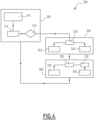
- FIG. 4 represents an example of a system management method 30 which can optionally be implemented by the electronic control device 100.
- the electronic control device 100 is implemented by one or more electronic circuits, for example by a programmable logic controller (PLC).
- PLC programmable logic controller
- the electronic control device 100 is configured to manage power supply parameters of at least part of the electrical loads and/or automatically disconnect or reconnect one or more of the electrical loads as a function of the measured current.
- the electronic control device 100 is connected to sensors making it possible to determine the electric current circulating in the installation.
- the system 30 comprises devices for measuring electrical quantities, such as the current and/or the electrical voltage and/or the electrical power, associated with the electrical loads (at least for the main loads) and with the electrical sources.
- These measuring devices may include current sensors and/or voltage sensors or any other appropriate measuring device.
- the electronic control device 100 is also connected to electrical switching devices, such as remotely controllable switches, to selectively disconnect or reconnect one or more of the electrical loads, or even all of the electrical loads.
- the electrical switching devices may be relays, or contactors, or semiconductor-based power switches, or any other equivalent device.
- the electronic control device 100 can also communicate with one or more of the main electrical loads 80,82,42 and 44 in order to modulate the electrical consumption and/or the electrical production of these sources or these loads (when they allow it). or are reversible).
- This Communication is, for example, ensured by communication devices such as a communication bus, for example of “ModBus” or “Open Charge Point Protocol” (OCPP) technology or equivalent.
- OCPP Open Charge Point Protocol
- control device 100 is configured to, depending on the measured current, manage power supply parameters of at least part of the electrical loads, in order to reduce the electrical current consumed by these loads and/or manage power parameters. operation in order to respect the current threshold imposed by a main circuit breaker connected between the electrical installation and the electrical distribution network.
- it may involve automatically disconnecting or reconnecting one or more of the electrical loads as a function of the current measured as part of a load shedding action, to adjust the electrical power consumed by the electrical loads as a function of the electrical power subscribed to the network manager 32 (on which the threshold of the main circuit breaker 11 is set) and the electrical power that the secondary source 34 is able to provide.
- the device 30 comprises measuring devices 33, 35 capable of measuring the electrical power supplied by the electrical sources (in particular by the network 32 and by the secondary source 34) and/or the electrical power passing through the different branches of the connection device 36. It may, for example, be one or more current sensors and/or voltage sensors and/or Wattmeters (W) and/or any equivalent or appropriate measuring device.
- a first measuring device 33 is associated with the network 32 while a second measuring device 35 is associated with the source 34.
- This method makes it possible to monitor and manage the consumption of electrical loads according to the contract subscribed to with the network manager 32, in particular so that the current supplied by the network does not exceed the threshold set by the subscription (for example, 40 A or 60 A) because this could lead to tripping of the main circuit breaker 11, in particular to detect if the current supplied by the network 32 exceeds the threshold fixed by the subscription (I_Grid in relation to I_threshold of element 11).
- control device 100 measures electrical quantities by means of sensors and measuring devices and determines (directly and/or by calculations) values of electrical currents and/or electrical power values at one or more locations W of the distribution installation.
- control device 100 compares the measured quantities 310 with reference quantities, which may be protection thresholds, the exceeding of which indicates the appearance of an overcurrent.
- the comparison can be carried out by calculating a ratio between electrical quantities (a measured electrical quantity and a predefined limit) and comparing this ratio to a predefined numerical value.
- current ratio is defined as equal to the ratio of the current circulating at a point of the installation (in the distributor 36) divided by a current threshold, such as the protection threshold previously defined (for example equal to 96 A or 120 A).
- a power ratio defined as equal to the electrical power delivered by the network 32 divided by a predefined electrical power limit (these powers being able to be instantaneous powers, or powers averaged over the same duration)
- At least one of said ratios is calculated during step 312, then in step 314, the control device 100 determines whether an overcurrent has been identified from the value of the calculated ratio(s).
- control device 100 implements a load shedding process to interrupt the operation of at least one of the main loads, in order to reduce the electrical consumption and thus adapt the consumption according to the power available on the network 32 (depending on the supply contract subscribed, which limits the power or current available) and the power available on secondary sources, in particular on intermittent sources such as photovoltaic generators when the secondary source 34 includes such generators.
- the control device 100 automatically determines which loads can be shed. For example, a list of electrical loads managed by the system and their characteristics is first recorded in memory.
- This determination is for example implemented according to a predefined control law, for example by means of known load shedding management algorithms.
- An example of an adjustable load whose consumption can be varied gradually is heating or air conditioning equipment whose set temperature can be modified to heat less (or cool less). It may also be an electric vehicle charging station whose charging rate is reduced.
- this regulation is carried out by means of the regulation device integrated into the corresponding electrical load.
- control device 100 automatically sends orders to reduce the consumption of one or more loads (step 322) and/or orders to disconnect a load (step 324).
- the disconnection order is sent directly to the load so that it interrupts itself, or to a switching device located between the distributor 36 and an input of power supply of the load, as will be explained in more detail through examples presented below.
- step 306 the load(s) are restored, for example once the fault condition has disappeared and/or at the expiration of a predefined time delay.
- control device 100 automatically determines which of the previously targeted loads can be restored. This determination can be carried out as a function of known characteristics of said loads, following a predefined control law, like the method of step 320.
- control device 100 automatically sends orders to gradually restore the consumption of one or more variable loads (step 334) and/or orders to reconnect a load (step 336) after a time delay (step 332).
- Step 302 is then repeated.
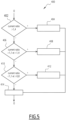
- FIG. 5 represents an example of simplified implementation of the steps of shedding one or more electrical loads of the system of the method of the Figure 3 .
- the method 400 which details an example of operation of the step implemented in the aforementioned block 302, begins after the ratios previously described have been calculated.
- step 402 the current ratio (noted “current_ratio” on the figure 5 ) is compared to a first threshold (here chosen equal to 1.4 although other examples are possible). If the calculated ratio is greater than the first threshold, then the load(s) concerned are immediately interrupted (step 404 then step 304).
- a first threshold here chosen equal to 1.4 although other examples are possible.
- the current ratio (current_ratio) is compared (step 406) to a second threshold (here chosen to be equal to 1.1 although other examples are possible). If the calculated ratio is greater than the second threshold, while being lower than the first threshold, then the load(s) concerned are interrupted after a first delay period, for example equal to 20 seconds (step 408 then step 304).
- step 410 the current ratio (noted “current ratio” on the figure 5 ) is compared to predefined thresholds (here equal to 0.8 and 1.1, other examples being nevertheless possible). If the calculated ratio is between the first threshold and the second threshold then the load(s) concerned are interrupted after a second delay period, for example equal to 300 seconds (step 412 then step 304).
- the values of the current ratio thresholds could take different values. These threshold values are preferably chosen according to the properties of the protection element 11 of the installation and the desired level of electrical protection. The same goes for the timeout values.
- FIG. 6 details an example of operation (process 500) of the step implemented in the aforementioned block 304 to control the shedding of one or more electrical loads.
- load shedding acts as a priority on certain loads rather than others (in particular loads that can be easily modulated or disconnected) depending on their nature. For example, we aim first to disconnect or limit the charge of the electric vehicle, then that of a load such as the water heater or air conditioning. The choice of the water heater is justified here by the fact that the temporary shutdown of the water heater will not degrade the comfort of the users since there is a reserve of hot water from which the user can draw even when the means of water heater heating are temporarily disabled.
- the method begins at step 502, once a load shedding order has been issued and, where applicable, the duration corresponding to the time delay has elapsed.
- step 504 the electronic control device 100 checks whether an electric vehicle is connected to the charging terminal and checks whether the batteries of this vehicle are not full.
- step 506 the water heater is temporarily interrupted.
- the control device orders the disconnection of the water heater connected to the secondary box 40, then triggers a time counter, during which the power supply to the water heater will remain interrupted.
- a new current ratio is calculated during step 508, then a comparison with the limit threshold is carried out during step 510.
- step 510 may include comparing the ratio with a first value specifically chosen according to the threshold defined in the contract.
- the method 500 ends at step 512.
- a message can be sent to indicate that load shedding is active.
- the electronic control device disconnects another electrical load.
- the heat pump is disconnected from the secondary panel 40 and a time delay is imposed during which this load will not be replenished. The process can then end directly at step 512.
- a new charging setpoint is calculated for the electric vehicle, for example to reduce the electrical power consumed.
- the control device checks whether the charging setpoint of the charging station is negative, indicating that the current to be reduced is greater than the sole demand of the electric vehicle. If this is the case, then during a step 522 a new load setpoint is chosen equal to zero to deactivate the charging terminal and the method goes to step 506 previously described, to disconnect another load.
- the new calculated charging setpoint is assigned to the charging terminal which will be transmitted to the electric vehicle during a step 520.
- the process then ends at step 512.
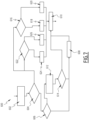
- FIG. 7 details an example (process 600) of operation of the step implemented in the aforementioned block 306 to reactivate one or more electrical loads once the load shedding must end.
- the process begins at step 602, once an order to end load shedding has been issued.
- step 604 the electronic control device checks if at least one or the other of the water heater or the heat pump (or air conditioner) is stopped, following load shedding.
- the device 100 checks whether an electric vehicle is connected to the charging terminal and checks whether the batteries of this vehicle are not full.
- step 608 a message is sent (or a register is updated) to indicate that load shedding is complete. The process then ends during a step 610.
- step 606 the control device calculates a new charging setpoint for the charging terminal, for example to increase the electrical power consumed by the electric vehicle.
- control device 100 checks whether the new calculated load setpoint is greater than the maximum setpoint. If this is the case, then the process proceeds to step 608 and ends at step 610.
- step 610 In the case where the new calculated load setpoint is less than the maximum setpoint, then we go directly to step 610.
- step 604 if the controller 100 identifies that at least one of the other loads, such as the water heater 80 or the heat pump of the air conditioner 82, is already stopped, then, a or several checks are put in place.
- the other loads such as the water heater 80 or the heat pump of the air conditioner 82
- a step 616 the device 100 checks whether the time delay imposed on the heat pump 82 (or air conditioner) connected to the secondary panel 40 has come to an end. If this is the case, then, in step 618, the heat pump 82 (or air conditioner) is reconnected. Otherwise, during a step 620, the heat pump 82 (or air conditioner) remains disconnected. The process ends at step 610.
- step 622 the control device checks whether the time delay imposed on the water heater has come to an end. If this is the case, then, in a step 624, the corresponding load is reconnected to resupply the water heater. Otherwise, during a step 626, the load remains disconnected. The process ends at step 610.
- these steps and this method could be entirely omitted, as could the electronic control device, as well as said measuring and control means (the electrical switching devices controlled by the electronic control device).
Landscapes
- Engineering & Computer Science (AREA)
- Power Engineering (AREA)
- Physics & Mathematics (AREA)
- General Physics & Mathematics (AREA)
- Transportation (AREA)
- Mechanical Engineering (AREA)
- Remote Monitoring And Control Of Power-Distribution Networks (AREA)
- Supply And Distribution Of Alternating Current (AREA)
Claims (10)
- Elektrisches Verteilungssystem (30) zum Verteilen von elektrischen Strömen zwischen einem elektrischen Verteilungsnetz und einer häuslichen Verteilungsinstallation, wobei das elektrische Verteilungssystem Folgendes umfasst:- ein elektrisches Mehrquellen-Schaltgerät (38), das konfiguriert ist, um zwischen zwei Zuständen zu schalten, die den Fluss von elektrischen Strömen in zwei elektrischen Leitungswegen, die jeweils eine Vielzahl von elektrischen Leitern (L, N) umfassen, zulassen bzw. verhindern;- eine elektrische Anschlussvorrichtung (36), die an dem Ausgang des elektrischen Schaltgeräts angeschlossen ist, wobei die Anschlussvorrichtung konfiguriert ist, um die zwei elektrischen Leitungswege am Ausgang des Schaltgeräts zu verlängern;wobei das elektrische Schaltgerät (38) konfiguriert ist, um an einem ersten Eingang einen ersten der zwei elektrischen Leitungswege mit einem elektrischen Verteilungsnetz (32) zu verbinden, wobei das elektrische Schaltgerät konfiguriert ist, um an seinem zweiten Eingang den zweiten der zwei elektrischen Leitungswege mit einer Hilfsstromquelle (34) zu verbinden;wobei die Anschlussvorrichtung (36) konfiguriert ist, um jeden elektrischen Leitungsweg mit einer oder mehreren elektrischen Lasten (40, 42, 44) am Ausgang des elektrischen Schaltgeräts zu verbinden;wobei das elektrische Verteilungssystem dadurch gekennzeichnet ist, dass die elektrische Anschlussvorrichtung (36) einen Verbindungspunkt umfasst, in dem die entsprechenden elektrischen Leiter (L, N) von jedem elektrischen Leitungsweg miteinander verbunden sind, wobei das elektrische Mehrquellen-Schaltgerät (38) einen einzelnen Trennungspunkt bildet, der in der Lage ist, die mit dem ersten Eingang und dem zweiten Eingang verbundenen elektrischen Quellen gleichzeitig vom Rest des elektrischen Verteilungssystems (30) zu trennen.
- System nach Anspruch 1, wobei die elektrische Anschlussvorrichtung (36) eine H-Brücke für jede elektrische Phase oder jeden Nullleiter bildet.
- System nach einem der vorherigen Ansprüche, wobei die elektrische Anschlussvorrichtung (36) Verbindungsleiter aus einem elektrisch leitenden Material umfasst, wobei jeder Verbindungsleiter mit einer elektrischen Phase oder einem Nullleiter assoziiert ist.
- System nach einem der vorherigen Ansprüche, wobei die elektrische Anschlussvorrichtung (36) für jede elektrische Phase oder jeden Nullleiter eine Gruppe von elektrischen Leitern umfasst, umfassend:- mindestens einen ersten Leiter, um den ersten elektrischen Leitungsweg zu bilden, der mit dieser Phase oder diesem Nullleiter assoziiert ist,- mindestens einen zweiten Leiter, um den mit dieser Phase oder diesem Nullleiter assoziierten zweiten elektrischen Leitungsweg zu bilden, und- einen Verbindungspunkt, der mit dieser Phase oder diesem Nullleiter assoziiert ist, der den mindestens einen ersten Leiter mit dem mindestens einen zweiten Leiter dieser Phase oder dieses Nullleiters verbindet.
- System nach einem der vorherigen Ansprüche, wobei jeder Verbindungspunkt der elektrischen Anschlussvorrichtung (36) eine Stromstärke von 63 Ampere aufweist.
- System nach einem der Ansprüche 1 bis 4, wobei jeder Verbindungspunkt der elektrischen Anschlussvorrichtung (36) eine Stromstärke von 125 Ampere aufweist.
- System nach einem der vorherigen Ansprüche, wobei jeder von dem ersten elektrischen Leitungsweg und dem zweiten elektrischen Leitungsweg der elektrischen Anschlussvorrichtung (36) eine Stromstärke von 63 Ampere aufweist.
- System nach einem der vorherigen Ansprüche, wobei ein Teil der elektrischen Lasten geeignet ist, um mit dem ersten elektrischen Leitungsweg verbunden zu werden und ein anderer Teil der elektrischen Lasten (42, 44) dazu geeignet ist, mit dem zweiten elektrischen Leitungsweg verbunden zu werden.
- System nach einem der vorherigen Ansprüche, wobei die elektrische Hilfsquelle (34) einen oder mehrere photovoltaische Generatoren umfasst.
- Elektrische Verteilungsinstallation (1), insbesondere für häuslichen Gebrauch, umfassend ein elektrisches Verteilungssystem (30) nach einem der vorherigen Ansprüche.
Priority Applications (7)
| Application Number | Priority Date | Filing Date | Title |
|---|---|---|---|
| US17/947,247 US12015273B2 (en) | 2021-09-24 | 2022-09-19 | Electricity distribution system for a domestic installation comprising multiple electrical sources |
| US17/947,268 US12456862B2 (en) | 2021-09-24 | 2022-09-19 | Electricity distribution system for a domestic installation comprising multiple electrical sources |
| AU2022235581A AU2022235581A1 (en) | 2021-09-24 | 2022-09-21 | Electricity distribution system for a domestic installation comprising multiple electrical sources |
| AU2022235584A AU2022235584A1 (en) | 2021-09-24 | 2022-09-21 | Electricity distribution system for a domestic installation comprising multiple electrical sources |
| CN202211165922.9A CN115864362A (zh) | 2021-09-24 | 2022-09-23 | 用于包括多个电源的家用设施的配电系统 |
| CN202211166280.4A CN115864363A (zh) | 2021-09-24 | 2022-09-23 | 用于包括多个电源的家用设施的配电系统 |
| EP22197840.6A EP4156437B1 (de) | 2021-09-24 | 2022-09-26 | Stromverteilungssystem für eine hausanlage mit mehreren elektrischen quellen |
Applications Claiming Priority (1)
| Application Number | Priority Date | Filing Date | Title |
|---|---|---|---|
| FR2110100A FR3127648A1 (fr) | 2021-09-24 | 2021-09-24 | Système de distribution d’électricité pour une installation domestique, procédé de gestion d’un tel système de distribution d’électricité |
Publications (3)
| Publication Number | Publication Date |
|---|---|
| EP4156438A1 EP4156438A1 (de) | 2023-03-29 |
| EP4156438C0 EP4156438C0 (de) | 2024-06-26 |
| EP4156438B1 true EP4156438B1 (de) | 2024-06-26 |
Family
ID=78212337
Family Applications (2)
| Application Number | Title | Priority Date | Filing Date |
|---|---|---|---|
| EP22305033.7A Active EP4156438B1 (de) | 2021-09-24 | 2022-01-14 | Stromverteilungssystem für eine heimanlage mit mehreren stromquellen |
| EP22197487.6A Active EP4156436B1 (de) | 2021-09-24 | 2022-09-23 | Stromverteilungssystem für eine hausanlage, verfahren zur verwaltung eines solchen stromverteilungssystems |
Family Applications After (1)
| Application Number | Title | Priority Date | Filing Date |
|---|---|---|---|
| EP22197487.6A Active EP4156436B1 (de) | 2021-09-24 | 2022-09-23 | Stromverteilungssystem für eine hausanlage, verfahren zur verwaltung eines solchen stromverteilungssystems |
Country Status (5)
| Country | Link |
|---|---|
| US (1) | US20230093980A1 (de) |
| EP (2) | EP4156438B1 (de) |
| CN (1) | CN115864361A (de) |
| AU (1) | AU2022235576A1 (de) |
| FR (1) | FR3127648A1 (de) |
Family Cites Families (6)
| Publication number | Priority date | Publication date | Assignee | Title |
|---|---|---|---|---|
| FR2432789A1 (fr) * | 1978-08-01 | 1980-02-29 | Brun Pierre | Repartiteur-limiteur de puissance pour installations electriques |
| US8331071B2 (en) * | 2009-06-12 | 2012-12-11 | Northern Power Systems Utility Scale, Inc. | Interconnection switching system and method for connecting a distributed energy resource to an electrical power system |
| US8422203B2 (en) * | 2010-09-17 | 2013-04-16 | Telect Inc. | Low-resistance telecommunications power distribution panel |
| WO2016176727A1 (en) * | 2015-05-01 | 2016-11-10 | The University Of Sydney | Operation scheduling of power generation, storage and load |
| FR3067875B1 (fr) * | 2017-06-20 | 2019-07-19 | Latelec | Procede et architecture d'alimentation electrique de reseau domestique embarque |
| EP4032161A1 (de) * | 2019-09-17 | 2022-07-27 | Span. IO, Inc. | Systeme und verfahren zur verwaltung elektrischer lasten |
-
2021
- 2021-09-24 FR FR2110100A patent/FR3127648A1/fr not_active Withdrawn
-
2022
- 2022-01-14 EP EP22305033.7A patent/EP4156438B1/de active Active
- 2022-09-19 US US17/947,221 patent/US20230093980A1/en active Pending
- 2022-09-21 AU AU2022235576A patent/AU2022235576A1/en active Pending
- 2022-09-23 CN CN202211162577.3A patent/CN115864361A/zh active Pending
- 2022-09-23 EP EP22197487.6A patent/EP4156436B1/de active Active
Also Published As
| Publication number | Publication date |
|---|---|
| AU2022235576A1 (en) | 2023-04-13 |
| EP4156438C0 (de) | 2024-06-26 |
| EP4156436B1 (de) | 2024-07-31 |
| FR3127648A1 (fr) | 2023-03-31 |
| US20230093980A1 (en) | 2023-03-30 |
| EP4156438A1 (de) | 2023-03-29 |
| EP4156436C0 (de) | 2024-07-31 |
| CN115864361A (zh) | 2023-03-28 |
| EP4156436A1 (de) | 2023-03-29 |
Similar Documents
| Publication | Publication Date | Title |
|---|---|---|
| US12409749B2 (en) | Electric vehicle charger with automated grid-management and vehicle-to-home isolation/backup | |
| US20230148230A1 (en) | Meter collar adapter with electric load management and overcurrent protection | |
| US11695297B2 (en) | Photovoltaic disconnect device for storage integration | |
| WO2014191692A1 (fr) | Selection de phase pour installation electrique polyphasee | |
| US20240429717A1 (en) | Islanding meter socket adapter to connect multiple bidirectional distributed energy resources | |
| EP4156437B1 (de) | Stromverteilungssystem für eine hausanlage mit mehreren elektrischen quellen | |
| US11693031B2 (en) | Electric meter collar adaptor to divert power to distributed power generation resources | |
| EP4156438B1 (de) | Stromverteilungssystem für eine heimanlage mit mehreren stromquellen | |
| JP6971196B2 (ja) | 電力システムおよび切替装置 | |
| US12015273B2 (en) | Electricity distribution system for a domestic installation comprising multiple electrical sources | |
| US12381413B1 (en) | Energy controller in meter socket adapter connected household microgrid | |
| EP3596791A1 (de) | System zur versorgung eines bordnetzes eines unterseebootes mit elektrischer energie | |
| EP3996226A1 (de) | Verfahren und systeme für die automatische konfiguration eines elektrischen mikronetzes | |
| FR3101734A3 (fr) | Fiche de transfert automatique | |
| FR3150742A1 (fr) | Installation de recharge pour véhicules électriques | |
| WO2011135239A1 (fr) | Dispositif de sécurité pour panneaux photovoltaiques | |
| EP4664706A1 (de) | Vorrichtung zur verwaltung der stromversorgung eines lokalen netzwerks | |
| FR3120753A3 (fr) | Procédé et dispositif de répartition d’énergie renouvelable sur un site | |
| FR3163220A1 (fr) | Dispositif de gestion d'alimentation d’un réseau local | |
| FR3163223A1 (fr) | Dispositif de gestion d'alimentation d’un réseau local | |
| FR3166108A1 (fr) | Système de chargement électrique d’un véhicule | |
| WO2025252918A1 (fr) | Dispositif de gestion d'alimentation d'un réseau local | |
| FR3150155A1 (fr) | Procédé de gestion d’un ensemble électrique | |
| FR2959620A1 (fr) | Dispositif de commutation et d'asservissement entre un interrupteur inverseur bipolaire et une prise bipolaire de type male. |
Legal Events
| Date | Code | Title | Description |
|---|---|---|---|
| PUAI | Public reference made under article 153(3) epc to a published international application that has entered the european phase |
Free format text: ORIGINAL CODE: 0009012 |
|
| STAA | Information on the status of an ep patent application or granted ep patent |
Free format text: STATUS: THE APPLICATION HAS BEEN PUBLISHED |
|
| AK | Designated contracting states |
Kind code of ref document: A1 Designated state(s): AL AT BE BG CH CY CZ DE DK EE ES FI FR GB GR HR HU IE IS IT LI LT LU LV MC MK MT NL NO PL PT RO RS SE SI SK SM TR |
|
| STAA | Information on the status of an ep patent application or granted ep patent |
Free format text: STATUS: REQUEST FOR EXAMINATION WAS MADE |
|
| 17P | Request for examination filed |
Effective date: 20230904 |
|
| RBV | Designated contracting states (corrected) |
Designated state(s): AL AT BE BG CH CY CZ DE DK EE ES FI FR GB GR HR HU IE IS IT LI LT LU LV MC MK MT NL NO PL PT RO RS SE SI SK SM TR |
|
| GRAP | Despatch of communication of intention to grant a patent |
Free format text: ORIGINAL CODE: EPIDOSNIGR1 |
|
| STAA | Information on the status of an ep patent application or granted ep patent |
Free format text: STATUS: GRANT OF PATENT IS INTENDED |
|
| INTG | Intention to grant announced |
Effective date: 20240118 |
|
| GRAS | Grant fee paid |
Free format text: ORIGINAL CODE: EPIDOSNIGR3 |
|
| GRAA | (expected) grant |
Free format text: ORIGINAL CODE: 0009210 |
|
| STAA | Information on the status of an ep patent application or granted ep patent |
Free format text: STATUS: THE PATENT HAS BEEN GRANTED |
|
| AK | Designated contracting states |
Kind code of ref document: B1 Designated state(s): AL AT BE BG CH CY CZ DE DK EE ES FI FR GB GR HR HU IE IS IT LI LT LU LV MC MK MT NL NO PL PT RO RS SE SI SK SM TR |
|
| REG | Reference to a national code |
Ref country code: GB Ref legal event code: FG4D Free format text: NOT ENGLISH |
|
| REG | Reference to a national code |
Ref country code: CH Ref legal event code: EP |
|
| REG | Reference to a national code |
Ref country code: DE Ref legal event code: R096 Ref document number: 602022004178 Country of ref document: DE |
|
| U01 | Request for unitary effect filed |
Effective date: 20240716 |
|
| U07 | Unitary effect registered |
Designated state(s): AT BE BG DE DK EE FI FR IT LT LU LV MT NL PT RO SE SI Effective date: 20240902 |
|
| PG25 | Lapsed in a contracting state [announced via postgrant information from national office to epo] |
Ref country code: HR Free format text: LAPSE BECAUSE OF FAILURE TO SUBMIT A TRANSLATION OF THE DESCRIPTION OR TO PAY THE FEE WITHIN THE PRESCRIBED TIME-LIMIT Effective date: 20240626 |
|
| PG25 | Lapsed in a contracting state [announced via postgrant information from national office to epo] |
Ref country code: GR Free format text: LAPSE BECAUSE OF FAILURE TO SUBMIT A TRANSLATION OF THE DESCRIPTION OR TO PAY THE FEE WITHIN THE PRESCRIBED TIME-LIMIT Effective date: 20240927 |
|
| PG25 | Lapsed in a contracting state [announced via postgrant information from national office to epo] |
Ref country code: NO Free format text: LAPSE BECAUSE OF FAILURE TO SUBMIT A TRANSLATION OF THE DESCRIPTION OR TO PAY THE FEE WITHIN THE PRESCRIBED TIME-LIMIT Effective date: 20240926 Ref country code: HR Free format text: LAPSE BECAUSE OF FAILURE TO SUBMIT A TRANSLATION OF THE DESCRIPTION OR TO PAY THE FEE WITHIN THE PRESCRIBED TIME-LIMIT Effective date: 20240626 Ref country code: GR Free format text: LAPSE BECAUSE OF FAILURE TO SUBMIT A TRANSLATION OF THE DESCRIPTION OR TO PAY THE FEE WITHIN THE PRESCRIBED TIME-LIMIT Effective date: 20240927 Ref country code: RS Free format text: LAPSE BECAUSE OF FAILURE TO SUBMIT A TRANSLATION OF THE DESCRIPTION OR TO PAY THE FEE WITHIN THE PRESCRIBED TIME-LIMIT Effective date: 20240926 |
|
| PG25 | Lapsed in a contracting state [announced via postgrant information from national office to epo] |
Ref country code: PL Free format text: LAPSE BECAUSE OF FAILURE TO SUBMIT A TRANSLATION OF THE DESCRIPTION OR TO PAY THE FEE WITHIN THE PRESCRIBED TIME-LIMIT Effective date: 20240626 |
|
| PG25 | Lapsed in a contracting state [announced via postgrant information from national office to epo] |
Ref country code: IS Free format text: LAPSE BECAUSE OF FAILURE TO SUBMIT A TRANSLATION OF THE DESCRIPTION OR TO PAY THE FEE WITHIN THE PRESCRIBED TIME-LIMIT Effective date: 20241026 |
|
| PG25 | Lapsed in a contracting state [announced via postgrant information from national office to epo] |
Ref country code: CZ Free format text: LAPSE BECAUSE OF FAILURE TO SUBMIT A TRANSLATION OF THE DESCRIPTION OR TO PAY THE FEE WITHIN THE PRESCRIBED TIME-LIMIT Effective date: 20240626 |
|
| PG25 | Lapsed in a contracting state [announced via postgrant information from national office to epo] |
Ref country code: SK Free format text: LAPSE BECAUSE OF FAILURE TO SUBMIT A TRANSLATION OF THE DESCRIPTION OR TO PAY THE FEE WITHIN THE PRESCRIBED TIME-LIMIT Effective date: 20240626 |
|
| PG25 | Lapsed in a contracting state [announced via postgrant information from national office to epo] |
Ref country code: ES Free format text: LAPSE BECAUSE OF FAILURE TO SUBMIT A TRANSLATION OF THE DESCRIPTION OR TO PAY THE FEE WITHIN THE PRESCRIBED TIME-LIMIT Effective date: 20240626 Ref country code: SM Free format text: LAPSE BECAUSE OF FAILURE TO SUBMIT A TRANSLATION OF THE DESCRIPTION OR TO PAY THE FEE WITHIN THE PRESCRIBED TIME-LIMIT Effective date: 20240626 |
|
| PG25 | Lapsed in a contracting state [announced via postgrant information from national office to epo] |
Ref country code: SM Free format text: LAPSE BECAUSE OF FAILURE TO SUBMIT A TRANSLATION OF THE DESCRIPTION OR TO PAY THE FEE WITHIN THE PRESCRIBED TIME-LIMIT Effective date: 20240626 Ref country code: SK Free format text: LAPSE BECAUSE OF FAILURE TO SUBMIT A TRANSLATION OF THE DESCRIPTION OR TO PAY THE FEE WITHIN THE PRESCRIBED TIME-LIMIT Effective date: 20240626 Ref country code: PL Free format text: LAPSE BECAUSE OF FAILURE TO SUBMIT A TRANSLATION OF THE DESCRIPTION OR TO PAY THE FEE WITHIN THE PRESCRIBED TIME-LIMIT Effective date: 20240626 Ref country code: IS Free format text: LAPSE BECAUSE OF FAILURE TO SUBMIT A TRANSLATION OF THE DESCRIPTION OR TO PAY THE FEE WITHIN THE PRESCRIBED TIME-LIMIT Effective date: 20241026 Ref country code: ES Free format text: LAPSE BECAUSE OF FAILURE TO SUBMIT A TRANSLATION OF THE DESCRIPTION OR TO PAY THE FEE WITHIN THE PRESCRIBED TIME-LIMIT Effective date: 20240626 Ref country code: CZ Free format text: LAPSE BECAUSE OF FAILURE TO SUBMIT A TRANSLATION OF THE DESCRIPTION OR TO PAY THE FEE WITHIN THE PRESCRIBED TIME-LIMIT Effective date: 20240626 |
|
| U20 | Renewal fee for the european patent with unitary effect paid |
Year of fee payment: 4 Effective date: 20250127 |
|
| PLBE | No opposition filed within time limit |
Free format text: ORIGINAL CODE: 0009261 |
|
| STAA | Information on the status of an ep patent application or granted ep patent |
Free format text: STATUS: NO OPPOSITION FILED WITHIN TIME LIMIT |
|
| 26N | No opposition filed |
Effective date: 20250327 |
|
| REG | Reference to a national code |
Ref country code: CH Ref legal event code: PL |
|
| PG25 | Lapsed in a contracting state [announced via postgrant information from national office to epo] |
Ref country code: MC Free format text: LAPSE BECAUSE OF FAILURE TO SUBMIT A TRANSLATION OF THE DESCRIPTION OR TO PAY THE FEE WITHIN THE PRESCRIBED TIME-LIMIT Effective date: 20240626 |
|
| PG25 | Lapsed in a contracting state [announced via postgrant information from national office to epo] |
Ref country code: CH Free format text: LAPSE BECAUSE OF NON-PAYMENT OF DUE FEES Effective date: 20250131 |
|
| PG25 | Lapsed in a contracting state [announced via postgrant information from national office to epo] |
Ref country code: IE Free format text: LAPSE BECAUSE OF NON-PAYMENT OF DUE FEES Effective date: 20250114 |
|
| U20 | Renewal fee for the european patent with unitary effect paid |
Year of fee payment: 5 Effective date: 20260126 |
|
| PGFP | Annual fee paid to national office [announced via postgrant information from national office to epo] |
Ref country code: GB Payment date: 20260126 Year of fee payment: 5 |