EP4156436B1 - Stromverteilungssystem für eine hausanlage, verfahren zur verwaltung eines solchen stromverteilungssystems - Google Patents
Stromverteilungssystem für eine hausanlage, verfahren zur verwaltung eines solchen stromverteilungssystems Download PDFInfo
- Publication number
- EP4156436B1 EP4156436B1 EP22197487.6A EP22197487A EP4156436B1 EP 4156436 B1 EP4156436 B1 EP 4156436B1 EP 22197487 A EP22197487 A EP 22197487A EP 4156436 B1 EP4156436 B1 EP 4156436B1
- Authority
- EP
- European Patent Office
- Prior art keywords
- electrical
- distributor
- loads
- current
- installation
- Prior art date
- Legal status (The legal status is an assumption and is not a legal conclusion. Google has not performed a legal analysis and makes no representation as to the accuracy of the status listed.)
- Active
Links
Images


Classifications
-
- H—ELECTRICITY
- H02—GENERATION; CONVERSION OR DISTRIBUTION OF ELECTRIC POWER
- H02J—ELECTRIC POWER NETWORKS; CIRCUIT ARRANGEMENTS OR SYSTEMS FOR SUPPLYING OR DISTRIBUTING ELECTRIC POWER; SYSTEMS FOR STORING ELECTRIC ENERGY
- H02J3/00—Circuit arrangements for AC mains or AC distribution networks
- H02J3/04—Arrangements for connecting networks of the same frequency but supplied from different sources
- H02J3/06—Controlling the transfer of power between connected networks; Controlling load sharing between connected networks
-
- H—ELECTRICITY
- H02—GENERATION; CONVERSION OR DISTRIBUTION OF ELECTRIC POWER
- H02J—ELECTRIC POWER NETWORKS; CIRCUIT ARRANGEMENTS OR SYSTEMS FOR SUPPLYING OR DISTRIBUTING ELECTRIC POWER; SYSTEMS FOR STORING ELECTRIC ENERGY
- H02J3/00—Circuit arrangements for AC mains or AC distribution networks
- H02J3/007—Arrangements for selectively connecting one or more loads to one or more power sources or power lines
-
- B—PERFORMING OPERATIONS; TRANSPORTING
- B60—VEHICLES IN GENERAL
- B60L—PROPULSION OF ELECTRICALLY-PROPELLED VEHICLES; SUPPLYING ELECTRIC POWER FOR AUXILIARY EQUIPMENT OF ELECTRICALLY-PROPELLED VEHICLES; ELECTRODYNAMIC BRAKE SYSTEMS FOR VEHICLES IN GENERAL; MAGNETIC SUSPENSION OR LEVITATION FOR VEHICLES; MONITORING OPERATING VARIABLES OF ELECTRICALLY-PROPELLED VEHICLES; ELECTRIC SAFETY DEVICES FOR ELECTRICALLY-PROPELLED VEHICLES
- B60L53/00—Methods of charging batteries, specially adapted for electric vehicles; Charging stations or on-board charging equipment therefor; Exchange of energy storage elements in electric vehicles
- B60L53/60—Monitoring or controlling charging stations
- B60L53/62—Monitoring or controlling charging stations in response to charging parameters, e.g. current, voltage or electrical charge
-
- G—PHYSICS
- G01—MEASURING; TESTING
- G01R—MEASURING ELECTRIC VARIABLES; MEASURING MAGNETIC VARIABLES
- G01R19/00—Arrangements for measuring currents or voltages or for indicating presence or sign thereof
- G01R19/0092—Measuring current only
-
- H—ELECTRICITY
- H02—GENERATION; CONVERSION OR DISTRIBUTION OF ELECTRIC POWER
- H02J—ELECTRIC POWER NETWORKS; CIRCUIT ARRANGEMENTS OR SYSTEMS FOR SUPPLYING OR DISTRIBUTING ELECTRIC POWER; SYSTEMS FOR STORING ELECTRIC ENERGY
- H02J3/00—Circuit arrangements for AC mains or AC distribution networks
- H02J3/04—Arrangements for connecting networks of the same frequency but supplied from different sources
-
- H—ELECTRICITY
- H02—GENERATION; CONVERSION OR DISTRIBUTION OF ELECTRIC POWER
- H02J—ELECTRIC POWER NETWORKS; CIRCUIT ARRANGEMENTS OR SYSTEMS FOR SUPPLYING OR DISTRIBUTING ELECTRIC POWER; SYSTEMS FOR STORING ELECTRIC ENERGY
- H02J3/00—Circuit arrangements for AC mains or AC distribution networks
- H02J3/38—Arrangements for feeding a single network from two or more generators or sources in parallel; Arrangements for feeding already energised networks from additional generators or sources in parallel
- H02J3/381—Dispersed generators
-
- H—ELECTRICITY
- H02—GENERATION; CONVERSION OR DISTRIBUTION OF ELECTRIC POWER
- H02J—ELECTRIC POWER NETWORKS; CIRCUIT ARRANGEMENTS OR SYSTEMS FOR SUPPLYING OR DISTRIBUTING ELECTRIC POWER; SYSTEMS FOR STORING ELECTRIC ENERGY
- H02J2101/00—Supply or distribution of decentralised, dispersed or local electric power generation
- H02J2101/20—Dispersed power generation using renewable energy sources
- H02J2101/22—Solar energy
- H02J2101/24—Photovoltaics
-
- H—ELECTRICITY
- H02—GENERATION; CONVERSION OR DISTRIBUTION OF ELECTRIC POWER
- H02J—ELECTRIC POWER NETWORKS; CIRCUIT ARRANGEMENTS OR SYSTEMS FOR SUPPLYING OR DISTRIBUTING ELECTRIC POWER; SYSTEMS FOR STORING ELECTRIC ENERGY
- H02J2103/00—Details of circuit arrangements for mains or AC distribution networks
- H02J2103/30—Simulating, planning, modelling, reliability check or computer assisted design [CAD] of electric power networks
- H02J2103/35—Grid-level management of power transmission or distribution systems, e.g. load flow analysis or active network management
-
- H—ELECTRICITY
- H02—GENERATION; CONVERSION OR DISTRIBUTION OF ELECTRIC POWER
- H02J—ELECTRIC POWER NETWORKS; CIRCUIT ARRANGEMENTS OR SYSTEMS FOR SUPPLYING OR DISTRIBUTING ELECTRIC POWER; SYSTEMS FOR STORING ELECTRIC ENERGY
- H02J2105/00—Networks for supplying or distributing electric power characterised by their spatial reach or by the load
- H02J2105/50—Networks for supplying or distributing electric power characterised by their spatial reach or by the load for selectively controlling the operation of the loads
- H02J2105/52—Networks for supplying or distributing electric power characterised by their spatial reach or by the load for selectively controlling the operation of the loads for limitation of the power consumption in the networks or in one section of the networks, e.g. load shedding or peak shaving
- H02J2105/53—Networks for supplying or distributing electric power characterised by their spatial reach or by the load for selectively controlling the operation of the loads for limitation of the power consumption in the networks or in one section of the networks, e.g. load shedding or peak shaving for partial power limitation, e.g. entering degraded or current limitation modes
-
- Y—GENERAL TAGGING OF NEW TECHNOLOGICAL DEVELOPMENTS; GENERAL TAGGING OF CROSS-SECTIONAL TECHNOLOGIES SPANNING OVER SEVERAL SECTIONS OF THE IPC; TECHNICAL SUBJECTS COVERED BY FORMER USPC CROSS-REFERENCE ART COLLECTIONS [XRACs] AND DIGESTS
- Y02—TECHNOLOGIES OR APPLICATIONS FOR MITIGATION OR ADAPTATION AGAINST CLIMATE CHANGE
- Y02B—CLIMATE CHANGE MITIGATION TECHNOLOGIES RELATED TO BUILDINGS, e.g. HOUSING, HOUSE APPLIANCES OR RELATED END-USER APPLICATIONS
- Y02B70/00—Technologies for an efficient end-user side electric power management and consumption
- Y02B70/30—Systems integrating technologies related to power network operation and communication or information technologies for improving the carbon footprint of the management of residential or tertiary loads, i.e. smart grids as climate change mitigation technology in the buildings sector, including also the last stages of power distribution and the control, monitoring or operating management systems at local level
- Y02B70/3225—Demand response systems, e.g. load shedding, peak shaving
-
- Y—GENERAL TAGGING OF NEW TECHNOLOGICAL DEVELOPMENTS; GENERAL TAGGING OF CROSS-SECTIONAL TECHNOLOGIES SPANNING OVER SEVERAL SECTIONS OF THE IPC; TECHNICAL SUBJECTS COVERED BY FORMER USPC CROSS-REFERENCE ART COLLECTIONS [XRACs] AND DIGESTS
- Y04—INFORMATION OR COMMUNICATION TECHNOLOGIES HAVING AN IMPACT ON OTHER TECHNOLOGY AREAS
- Y04S—SYSTEMS INTEGRATING TECHNOLOGIES RELATED TO POWER NETWORK OPERATION, COMMUNICATION OR INFORMATION TECHNOLOGIES FOR IMPROVING THE ELECTRICAL POWER GENERATION, TRANSMISSION, DISTRIBUTION, MANAGEMENT OR USAGE, i.e. SMART GRIDS
- Y04S20/00—Management or operation of end-user stationary applications or the last stages of power distribution; Controlling, monitoring or operating thereof
- Y04S20/20—End-user application control systems
- Y04S20/222—Demand response systems, e.g. load shedding, peak shaving
Definitions
- the invention relates to an electricity distribution system for a domestic installation.
- the invention also relates to a method for managing such an electricity distribution system.
- the main circuit breaker 11 is incapable of protecting the local installation in the case where the total electric current (I_total) equal to the sum of the current from the network (I_grid) and the current from the local source (I_PV) would be greater than a safety threshold I_seuil (for example 63 amps) when the two sources generate electricity which is consumed by the loads of the domestic installation, since the main circuit breaker 11 is not located on the same branch of installation than the local power source.
- I_total the total electric current
- I_grid the sum of the current from the network
- I_PV current from the local source
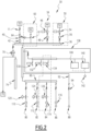
- FIG. 1 represents an example of such a configuration, in which a domestic electricity distribution installation 10 is configured to be supplied by a public distribution network 12 and by photovoltaic generators 13, these two power sources being connected by a connection common 14 to an input of the same distributor 16.
- the output of the distributor 16 is connected to conductors 18 which supply a plurality of domestic electrical loads 20.
- the main circuit breaker 11 may not trip when the total current (I_total) is greater than the safety threshold I_threshold (maximum current admissible by the table) while the current from the network (I_grid) remains below the threshold tripping of the main circuit breaker 11.
- the document US2021/083506 A1 is a patent application relating to an electrical load management system comprising a plurality of branch circuits, a sensor system and a control circuit.
- WO 2018 234330 A1 is an international application describing a method and a power supply system for a domestic network embedded in a passenger cabin.
- FIG. 2 represents an embodiment according to the invention of an electricity distribution system 30 for a domestic installation.
- At least part of the components of the system 30 are housed in an electrical panel, the latter being able to be at least partly installed in an electrical panel (for example a wall panel) or in an electrical cabinet.
- the system is configured to be powered by an electrical distribution network 32 (sector, or “grid” in English) and by at least one secondary power source 34.
- an electrical distribution network 32 system, or “grid” in English
- at least one secondary power source 34 secondary power source
- connection point comprising connection terminals intended to be connected to the network 32.
- connection terminals intended to be connected to the network 32.
- connection point may be a single-phase or polyphase connection point (for example three-phase) with or without neutral line.
- This protection element 11 may include an electrical protection device, such as a circuit breaker or a fuse or a power-limiting energy meter, for example.
- the protection element 11 comprises a circuit breaker, called the main circuit breaker, which corresponds to the main circuit breaker 11 described with reference to the figure 1 .
- the system 30 also includes a distributor 36 arranged to distribute an electric current in the installation.
- the distributor 36 makes it possible to connect several electrical loads to the same current input, for each electrical phase conductor (as well as for the neutral line, if applicable, depending on the type of installation).
- the electrical installation is a single-phase installation with a neutral line, other examples being nevertheless possible as a variant.
- system 30 could be adapted to operate in a three-phase installation.
- the distributor 36 comprises a plurality of connection bars, or connection rails, preferably made of copper or any suitable electrically conductive material, each connection bar being for example associated with an electrical phase (or with a neutral line).
- the distributor 36 is dimensioned to support and distribute an electric current of intensity greater than or equal to 96 amps, for example greater than or equal to 120 amps.
- the distributor 36 is configured to be connected, on the upstream side, to the electrical distribution network 32 and to each of the secondary power sources.
- a disconnect switch 40 located downstream of the protection element 11 is connected between the network 32 and the distributor 36.
- the disconnect switch is a modular switch (“miniature switch” in English).
- the current rating of the disconnector switch 40 is sized to carry the current of the protection element 11, for example 63 amperes.
- the main circuit breaker is therefore connected upstream of the distributor 36.
- the current threshold with which this main circuit breaker is adjusted generally depends on the subscription taken out with the network manager 32.
- a measuring device 42 Downstream of the disconnector switch 40 is here connected a measuring device 42, for example configured to measure an electric current and/or an electric power passing through the corresponding electrical conductor(s).
- the role of this measuring device 42 will be explained in the following.
- the system 30 comprises several secondary electrical power sources, examples of which will be described below with reference to the configuration illustrated in the figure 2 .
- the number and nature of the secondary electrical power sources may be different depending on the possible embodiments.
- At least one secondary electrical power source or generator comprises photovoltaic (PV) panels.
- the system 30 can thus include one or more photovoltaic generators acting as a source secondary power supply. It can also include a “dimmable” battery electricity storage system that can be a source or load.
- the first secondary electrical power source 34 comprises a first photovoltaic generator 44 composed of photovoltaic panels associated with an inverter connected to the distributor 36, for example, via electrical conductors here provided with a relay protection relay 46 and a differential circuit breaker equipped with a measuring circuit 48.
- the protection relay 46 and/or the differential circuit breaker equipped with a measuring circuit 48 could, however, be alternatively deported outside the system 30.
- the second secondary electrical power source 50 comprises a second photovoltaic generator 52 similar to 44 connected to the distributor 36, for example, via electrical conductors here provided with a protection relay 54 and a differential circuit breaker equipped with a measuring circuit 56 similar to those of the source 34.
- the third source 60 is an emergency source of the generator type 62.
- the system includes a disconnector switch (not marked) interlocked with the disconnector switch 40 and connected to the distributor 36.
- an electricity storage system for example comprising a set of electrochemical batteries, could be used as an additional electrical power source.
- This optional emergency source 60 includes a safety interlock 64, or interlocking device which makes it possible to interlock the source 32 with the source 62 to authorize only one of these two sources to be activated. be connected to the distributor 36.
- the device 64 makes it possible to choose which of the sources 32 or 62 supplies the distributor 36, by preventing the two sources from being connected simultaneously.
- the device 64 comprises a first switch, for example the disconnector switch 40 previously mentioned, which is placed between the network connection point 32 and the distributor 36, and a second switch 61 placed between the generator 62 and the distributor 36.
- the second switch is maintained in the open state as long as the first switch is in the closed state, and vice versa.
- the device 64 can be of mechanical or electromechanical or electronic type, other embodiments being nevertheless possible.
- the source(s) 50 and/or 60 could be omitted.
- the system 30 may include a lightning protection device.
- This lightning protection device is connected to the distributor 36, for example on the downstream side of the distributor 36.
- the lightning protection device comprises a varistor 70 connected between the distributor 36 and a connection point at the earth 72 of the electrical installation connected to the earth connection terminal 74.
- the distributor 36 is also configured to be connected, on the downstream side, to a plurality of electrical loads.
- the distributor 36 is thus capable of electrically supplying the electrical loads, by transferring at least part of the electrical current generated by one or more of the electrical sources 32, 34, 50 and 60 connected upstream. These main loads are here connected in parallel.
- the electrical charges correspond to references 80, 82, 84, 86 and 88 it being understood that this example is not limiting and that a different number of electrical charges can be provided as a variant.
- critical electrical charges or main charges
- domestic electrical charges 88 or secondary charges
- the main electrical loads 80, 82, 84 and 86 correspond to electrical loads capable of consuming significant electrical powers (compared to ordinary household electrical loads) and/or of consuming electrical currents of high electrical intensity, and/or to be active continuously for long periods of time (for example for more than 10 hours).
- the main electrical loads include one or more of the following elements: an electric vehicle or an electric vehicle charging station, a water heater, a heat pump (or air conditioner, or more generally a domestic heating installation ), an air conditioner or a swimming pool heating system.
- these loads correspond to references 80, 82, 84 and 86.
- the domestic electrical loads represented on the figure 2 by the numerical reference 88, consume less electrical power and their operation is generally intermittent.
- domestic electrical loads 88 are lighting elements, or domestic appliances plugged into electrical outlets domestic appliances, such as household appliances, multimedia devices, computer equipment, lighting fixtures, these examples being not limiting.
- each of said electrical loads 80, 82, 84, 86 and 88 is connected to the distributor 36 via an electrical conductor (or several phase and/or neutral conductors, depending on the nature of the installation electric).
- the electrical conductors are sized according to the maximum admissible current per corresponding electrical load, for example by being sized as accurately as possible so as not to have to oversize the electrical conductors. This saves the amount of material used and therefore reduces the cost of installation.
- the main electrical loads 80, 82, 84 and 86 can be connected to the distributor 36 via conductors associated with distribution combs 90 (or a secondary distributor), as is the case illustrated in the figure 2 , or they can be connected directly to the distributor 36 by an electrical conductor.
- the secondary electrical loads 88 whose connection terminals are generally gathered in a secondary box, can for their part be connected directly to the distributor 36 by an electrical conductor 92 protected by a circuit breaker 94 whose rating is dimensioned so as not to exceed the current maximum permissible secondary box, for example 63 A.
- the electrical conductors are connected to junction terminals allowing these electrical loads to be connected.
- the secondary electrical loads 88 can be connected by multiple secondary cables or conductors distributed from the secondary box.
- the load 80 is an electric water heater comprising at least one first heating means such as a heat pump or an electrical resistance.
- Load 82 is a heat pump (or air conditioner).
- Load 84 is another controlled load (for example a swimming pool pump).
- the charge 86 is a charging station for an electric vehicle.
- the electric water heater could only have one heating method (the resistance for example).
- the system 30 also includes an electronic control device 100 configured to automatically manage the distribution of electric current between the electrical loads.
- the electronic control device 100 is implemented by one or more electronic circuits, for example by a programmable logic controller (PLC).
- PLC programmable logic controller
- the electronic control device 100 comprises a processor, such as a programmable microcontroller or a microprocessor.
- the processor is coupled to a computer memory, or to any computer-readable data recording medium, which includes executable instructions and/or software code intended to implement a system management method 30 which will be described below. after when these instructions are executed by the processor.
- processor does not preclude, as a variant, at least part of the functions of the electronic control device 100 being carried out by other electronic components, such as a signal processing processor ( DSP), or a reprogrammable logic component (FPGA), or a specialized integrated circuit (ASIC), or any equivalent element, or any combination of these elements.
- DSP signal processing processor
- FPGA reprogrammable logic component
- ASIC specialized integrated circuit
- the electronic control device 100 is configured to manage power supply parameters of at least part of the electrical loads and/or automatically disconnect or reconnect one or more of the electrical loads as a function of the measured current, when the current circulating at through the distributor 36 exceeds a current threshold, such as a protection threshold.
- the electronic control device 100 is connected to sensors making it possible to determine the electric current circulating in the installation.
- the system 30 comprises devices for measuring electrical quantities, such as the current and/or the electrical voltage and/or the electrical power, associated with the electrical loads (at least for the main loads) and with the electrical sources.
- These measuring devices may include current sensors and/or voltage sensors or any other appropriate measuring device.
- measuring circuits 110, 112, 114 and 116 measure the currents flowing to the main loads 80, 82, 84 and 86.
- the measuring devices 42, 48 and 56 associated with the electrical sources can also be used for this purpose.
- a measuring device 42 is associated with the source 32, with each secondary source as well as with each main electrical load .
- the electronic control device 100 is also connected to electrical switching devices, such as remotely controllable switches, to selectively disconnect or reconnect one or more of the electrical loads, or even all electrical charges.
- electrical switching devices may be relays, or contactors, or semiconductor-based power switches, or any other equivalent device.
- each main load 80, 82 and 84 is associated an electrical switching device (respectively numbered 120, 124 and 126) which is selectively and reversibly switchable between an open state and a closed state to respectively disconnect the corresponding load from the distributor or to connect this load to distributor 36.
- an electrical switching device (respectively numbered 120, 124 and 126) which is selectively and reversibly switchable between an open state and a closed state to respectively disconnect the corresponding load from the distributor or to connect this load to distributor 36.
- the electronic control device 100 here placed in a control assembly 138, is configured to control the electrical switching devices 120, 124 and 126 in order to manage power supply parameters of at least part of the electrical loads.
- the device 100 is configured to, depending on the measured current, manage power supply parameters of at least part of the electrical loads, in order to reduce the electrical current consumed by these loads and/or manage operating parameters of at least part of these electrical loads to reduce the electrical current consumed by these electrical loads in order to respect the current threshold imposed by a main circuit breaker connected between the electrical installation and the electrical distribution network.
- the device 100 is also configured to manage the power supply parameters of at least part of the electrical loads in order to prevent the current delivered by the electrical sources through the distributor from exceeding the current limit imposed by the distributor.
- it may involve automatically disconnecting or reconnecting one or more of the electrical loads as a function of the current measured as part of a load shedding action, to prevent the current consumed circulating through the distributor 36 from exceeding the threshold of protection, and/or to adjust the electrical power consumed by the electrical loads as a function of the electrical power subscribed to from the network manager 32 (on which the threshold of the main circuit breaker 11 is set) and the electrical power that the secondary sources 34, 50 and 60 are able to provide.
- the electronic control device 100 is associated with control lines which are respectively associated with the electrical switching devices 120, 124 and 126. These lines are connected to a secondary distributor 90 supplied from the distributor 36 and are each provided with a controllable switch, such as a relay or a semi-conductor power switch, denoted 130, 132 and 134, in order to trigger the switching of the corresponding electrical switching device by selectively energizing the control line.
- a controllable switch such as a relay or a semi-conductor power switch
- the switch 120, 124 or 126 When the switch 120, 124 or 126 is in the open state, the corresponding electrical load is disconnected from the system 30 and cannot be electrically powered by a current circulating from the distributor 36.
- the electronic control device 100 can, also or alternatively, be connected to control means, such as a regulation device integrated into some of the electrical loads, to remotely control these electrical loads. (for example to reduce their consumption or to stop them temporarily).
- control means such as a regulation device integrated into some of the electrical loads
- loads such as a heat pump (or air conditioner), or a charging device for an electric vehicle, such as load 86 of the example illustrated in the figure 2 , which generally include such regulation devices (usually implemented by electronic controllers) which can communicate with the electronic control device 100.
- loads such as a heat pump (or air conditioner), or a charging device for an electric vehicle, such as load 86 of the example illustrated in the figure 2 , which generally include such regulation devices (usually implemented by electronic controllers) which can communicate with the electronic control device 100.
- the communication between the electronic control device 100 and the regulation device of the charging station for an electric vehicle is achieved here using a connection following the Open Charge Point Protocol (OCPP).
- OCPP Open Charge Point Protocol
- Other modes of communication could be used alternatively.
- the electronic control device 100 comprises a communications interface 140 such as a router or a gateway, which is in communications with a device for controlling one of the main loads (for example, the loading station 86), or even with an external communications network (for example the Internet network).
- a communications interface 140 such as a router or a gateway, which is in communications with a device for controlling one of the main loads (for example, the loading station 86), or even with an external communications network (for example the Internet network).
- the primary loads may be controlled by electrically energizing (or interrupting the power supply) a secondary junction terminal connected to an electrical load control input.
- the distribution system makes it possible to easily combine several power sources (and more particularly a photovoltaic source and a public network) to power a domestic installation comprising a plurality of electrical loads of different nature, while avoiding that the combination of several electrical sources does not generate electrical currents whose intensity would be dangerous for the installation and unstable in the event of absence of production of the photovoltaic panel.
- the device 100 makes it possible in particular to monitor and regulate two aspects: on the one hand, to guarantee compliance with the contract signed with the network manager 32 (or, more generally, respect the current threshold defined by the protection element 11) and, more generally, manage the self-consumption of the system, that is to say manage the electrical power supplied by the secondary sources.
- the device 100 could only be configured to monitor and regulate only one of these two aspects: respect the current threshold defined by the protection element 11 and manage the self-consumption of the system, or protect the distributor 36.
- the electronic control device 100 is configured to manage the consumption of the loads in order to reduce the current delivered by the electrical sources (such as the current coming from the network 32 and routed by the main circuit breaker) through the distributor 36.
- the device 100 is configured to monitor this current and to control the main electrical loads and/or the secondary sources in order to respect the safety threshold (I_threshold) of the main circuit breaker in order to avoid any untimely tripping, which would have a negative impact on the comfort of users of the electrical installation.
- I_threshold safety threshold
- the device 100 is configured to monitor this current and to control the main electrical loads and/or the secondary sources to respect the limit imposed by the distributor 36 (for example an electrical current of intensity 96 A or 120 A). .
- the device 100 can also be configured to monitor a current injection towards the network (linked to a consumption of loads less than the total production of additional sources) to force consumption by electrical loads.
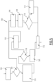
- FIG. 3 represents an example of a method of managing the system 30 or 200 implemented by the electronic control device 80.
- the network manager 32 involves monitoring and managing the consumption of electrical loads according to the contract subscribed to with the network manager 32, in particular so that the current supplied by the network does not exceed the threshold set by the subscription (for example, 40 A or 60 A) as this could lead to tripping of the main circuit breaker.
- the steps of this method can be implemented several times: a first time to detect if the current supplied by the network 32 exceeds the threshold fixed by the subscription (I_Grid relative to I_threshold of element 11) and a second time to detect if the current exceeds the protection threshold (I_grid + I_sum_of_sources) greater than I_Threshold of the distributor 36. These sequences of steps must themselves be repeated over time.
- the device 100 measures electrical quantities by means of sensors and measuring devices 42, 48, 56, 110, 112, 114 and 116 and determines (directly and/or by calculations) of electrical current values and/or electrical power values at one or more locations of the distribution installation.
- the device 100 compares the measured quantities 310 with reference quantities, which may be protection thresholds, the exceeding of which indicates the appearance of an overcurrent.
- reference quantities which may be protection thresholds, the exceeding of which indicates the appearance of an overcurrent.
- the comparison can be carried out by calculating a ratio between electrical quantities (a measured electrical quantity and a predefined limit) and comparing this ratio to a predefined numerical value.
- current ratio is defined as equal to the ratio of the current circulating at a point of the installation (in the distributor 36) divided by a current threshold, such as the protection threshold previously defined (for example equal to 96A or 120 A).
- a power ratio defined as equal to the electrical power delivered by the network 32 divided by a predefined electrical power limit (these powers being able to be instantaneous powers, or powers averaged over the same duration)
- At least one of said ratios is calculated during step 312, then in step 314, the device 100 determines whether an overcurrent has been identified from the value of the calculated ratio(s).
- the device 100 implements a load shedding process to interrupt the operation of at least one of the main loads, in order to reduce electrical consumption and thus reduce the current delivered by the electrical sources through the distributor 36 or the protection element 11 and/or adapt the consumption according to the power available on the network 32 (depending on the supply contract subscribed, which limits the power or current available) and the power available on secondary sources, in particular on intermittent sources such as photovoltaic generators 44 and 52.
- the device 100 automatically determines which loads can be shed. For example, a list of electrical loads managed by the system and their characteristics is first recorded in memory.
- This determination is for example implemented according to a predefined control law, for example by means of known load shedding management algorithms.
- An example of an adjustable load whose consumption can be varied gradually is heating or air conditioning equipment whose set temperature can be modified to heat less (or cool less). It may also be an electric vehicle charging station whose charging rate is reduced.
- this regulation is carried out by means of the regulation device integrated into the corresponding electrical load.
- the device 100 automatically sends orders to reduce the consumption of one or more loads (step 322) and/or orders to disconnect a load (step 324).
- the disconnection order is sent directly to the load so that it interrupts itself, or to a switching device located between the distributor 36 and an input of power supply of the load, as will be explained in more detail through examples presented below.
- step 306 the load(s) are restored, for example once the fault condition has disappeared and/or at the expiration of a predefined time delay.
- the device 100 automatically determines which of the previously targeted loads can be restored. This determination can be carried out as a function of known characteristics of said loads, following a predefined control law, like the method of step 320.
- the device 100 automatically sends orders to gradually restore the consumption of one or more variable loads (step 334) and/or orders to reconnect a load (step 336) after a delay of time delay (step 332).
- Step 302 is then repeated.
- FIG. 4 represents an example of simplified implementation of the steps of shedding one or more electrical loads of the system of the method of the Figure 3 .
- the method 400 which details an example of operation of the step implemented in the aforementioned block 302, begins after the ratios previously described have been calculated.
- step 402 the current ratio (noted “current_ratio” on the Figure 4 ) is compared to a first threshold (here chosen equal to 1.4 although other examples are possible). If the calculated ratio is greater than the first threshold, then the load(s) concerned are immediately interrupted (step 404 then step 304).
- a first threshold here chosen equal to 1.4 although other examples are possible.
- the current ratio (current_ratio) is compared (step 406) to a second threshold (here chosen to be equal to 1.1 although other examples are possible). If the calculated ratio is greater than the second threshold, while being lower than the first threshold, then the load(s) concerned are interrupted after a first delay period, for example equal to 20 seconds (step 408 then step 304).
- step 410 the current ratio (noted “current ratio” on the Figure 4 ) is compared to predefined thresholds (here equal to 0.8 and 1.1, other examples being nevertheless possible). If the calculated ratio is between the first threshold and the second threshold then the load(s) concerned are interrupted after a second delay period, for example equal to 300 seconds (step 412 then step 304).
- first and second threshold values could take different values. These threshold values are preferably chosen according to the properties of the protection element 11 of the installation and the level of electrical protection desired, for example according to the maximum current rating supported by the distributor and/or by the conductors electrical devices used to distribute current between electrical sources and loads. The same goes for the timeout values.
- first and second threshold values can be defined for the different iterations of the process (the first and second purposes mentioned above).
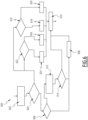
- FIG. 5 details an example of operation (process 500) of the step implemented in the aforementioned block 304 to control the shedding of one or more electrical loads.
- load shedding acts as a priority on certain loads rather than others (in particular loads that can be easily modulated or disconnected) depending on their nature. For example, we aim first to disconnect or limit the charge of the electric vehicle, then that of a load such as the water heater or air conditioning. The choice of the water heater is justified here by the fact that the temporary shutdown of the water heater will not degrade the comfort of the users since there is a reserve of hot water from which the user can draw even when the means of water heater heating are temporarily disabled.
- the method begins at step 502, once a load shedding order has been issued and, where applicable, the duration corresponding to the time delay has elapsed.
- step 504 the electronic control device 100 checks whether an electric vehicle is connected to the charging terminal and checks whether the batteries of this vehicle are not full.
- step 506 the water heater is temporarily interrupted.
- the device 100 controls the disconnection of the electrical load 80, here by means of the switching device 120, then triggers a time counter, during which the power supply to the load 80 will remain interrupted.
- a new current ratio is calculated during step 508, then a comparison with the limit threshold is carried out during step 510.
- step 510 may include comparing the ratio with a first value specifically chosen according to the threshold defined in the contract.
- the method 500 ends at step 512.
- a message can be sent to indicate that load shedding is active.
- the electronic control device 100 disconnects another electrical load.
- the heat pump (or air conditioner) (load 82) is disconnected, here by means of the switching device 124 and a time delay is imposed during which this load will not be replenished. The process can then end directly at step 512.
- a new charging setpoint is calculated for the electric vehicle, for example to reduce the electrical power consumed.
- the device 100 checks whether the charging setpoint of the charging station is negative, indicating that the current to be reduced is greater than the demand of the electric vehicle alone. If this is the case, then during a step 522 a new load setpoint is chosen equal to zero to deactivate the charging terminal and the method goes to step 506 previously described, to disconnect another load.
- the new calculated charging setpoint is assigned to the charging terminal which will be transmitted to the electric vehicle during a step 520.
- the process then ends in step 512.
- FIG. 6 details an example (process 600) of operation of the step implemented in the aforementioned block 306 to reactivate one or more electrical loads once the load shedding must end.
- the process begins at step 602, once an order to end load shedding has been issued.
- step 604 the electronic control device 100 checks if at least one or the other of the water heater or the heat pump (or air conditioner) is stopped, following load shedding.
- the device 100 checks whether an electric vehicle is connected to the charging terminal and checks whether the batteries of this vehicle are not full.
- step 608 a message is sent (or a register is updated) to indicate that load shedding is complete. The process then ends during a step 610.
- step 606 the device 100 calculates a new charging setpoint for the charging terminal, for example to increase the electrical power consumed by the electric vehicle.
- the device 100 checks whether the new calculated load setpoint is greater than the maximum setpoint. If this is the case, then the process proceeds to step 608 and ends at step 610.
- step 610 In the case where the new calculated load setpoint is less than the maximum setpoint, then we go directly to step 610.
- step 604 if the device 100 identifies that at least one of the other loads, such as the water heater or the air conditioner is already off, then one or more checks are put in place.
- the other loads such as the water heater or the air conditioner is already off
- a step 616 the device 100 checks whether the time delay imposed on the heat pump (or air conditioner) (load 82) has come to an end. If this is the case, then, in a step 618, the load 82 is reconnected (for example by acting on the switching device 124) to repower the heat pump (or air conditioner). In the case On the contrary, during a step 620, the load 82 remains disconnected. The process ends at step 610.
- the device 100 checks whether the time delay imposed on the water heater (load 80) has come to an end. If this is the case, then, in a step 624, the load 80 is reconnected (for example by means of the switching device 120) to repower the water heater. Otherwise, during a step 626, the load 80 remains disconnected. The process ends at step 610.
- steps could be performed in a different order. Some steps could be omitted.
- the example described does not preclude, in other embodiments, other steps being implemented jointly and/or sequentially with the steps described.
Landscapes
- Engineering & Computer Science (AREA)
- Power Engineering (AREA)
- Physics & Mathematics (AREA)
- General Physics & Mathematics (AREA)
- Transportation (AREA)
- Mechanical Engineering (AREA)
- Remote Monitoring And Control Of Power-Distribution Networks (AREA)
- Supply And Distribution Of Alternating Current (AREA)
Claims (14)
- Elektrisches Verteilungssystem (30) zum Verteilen von elektrischen Strömen zwischen einem elektrischen Verteilungsnetz und einer Hausverteilungsanlage, wobei das elektrische Verteilungssystem Folgendes umfasst:• einen Verteiler (36), der angeordnet ist, um elektrischen Strom in der Anlage verteilt, wobei der Verteiler konfiguriert ist, um stromaufwärts mit einem elektrischen Verteilungsnetz (32) und mit mindestens einer sekundären Stromversorgungsquelle (34, 50, 60) verbunden zu sein, wobei der Verteiler konfiguriert ist, um stromabwärts mit einer Vielzahl der elektrischen Lasten (80, 82, 84, 86, 88) verbunden zu sein,• eine elektronische Steuervorrichtung (100), die mit Messvorrichtungen verbunden ist, die mit den Quellen und den Lasten assoziiert sind, wobei diese Messvorrichtungen es ermöglichen, den in der Anlage fließenden elektrischen Strom und insbesondere den im Stromverteilungsnetz transportierten elektrischen Strom zu bestimmen,• wobei die elektronische Steuervorrichtung (100) konfiguriert ist, um abhängig von dem gemessenen Strom Parameter für die Stromversorgung mindestens eines Teils der elektrischen Lasten zu verwalten, um den von diesen elektrischen Lasten aufgenommenen elektrischen Strom zu reduzieren, und/oder Parameter für den Betrieb mindestens eines Teils der sekundären Stromquellen zu verwalten, um den von diesen Stromquellen bereitgestellten elektrischen Strom zu reduzieren,wobei das Stromverteilungssystem dadurch gekennzeichnet ist, dass die elektronische Steuervorrichtung konfiguriert ist, um eine erste Stromschwelle, die von einem Schutzelement (11) zwischen der elektrischen Anlage und dem Stromverteilungsnetz auferlegt wird, und eine zweite Stromschwelle, die einer von dem Verteiler (36) auferlegten Stromgrenze entspricht, einzuhalten, um zu verhindern, dass der von den elektrischen Quellen durch den Verteiler (36) bereitgestellte Strom die von dem Verteiler (36) auferlegte Stromgrenze übersteigt.
- System nach Anspruch 1, wobei ein Verwalten von Parametern für die Stromversorgung mindestens eines Teils der elektrischen Lasten Schritte umfasst, die mindestens darin bestehen, die elektrische Last oder die elektrischen Lasten (80, 82, 84, 86) automatisch zu trennen oder wieder zu verbinden oder den Stromverbrauch der elektrischen Last oder der elektrischen Lasten zu modulieren.
- System nach einem der vorherigen Ansprüche, wobei die Vielzahl von elektrischen Lasten (80, 82, 84, 86) eine oder mehrere der folgenden Komponenten umfassen: ein Elektrofahrzeug oder eine Ladestation für ein Elektrofahrzeug, einen Warmwasserbereiter, eine Wärmepumpe oder Klimaanlage oder eine Pumpe.
- System nach einem der vorherigen Ansprüche, wobei das System eine oder mehrere elektrische Schaltvorrichtungen (120, 124, 126) zum selektiven Trennen oder Wiederverbinden einer oder mehrerer der elektrischen Lasten umfasst, wobei die Schaltvorrichtung(en) von der elektronischen Steuervorrichtung gesteuert wird/werden.
- System nach einem der vorherigen Ansprüche, wobei mindestens eine der elektrischen Lasten (86) eine integrierte Regelvorrichtung aufweist, die mit der elektronischen Steuervorrichtung verbunden ist, wobei die integrierte Regelvorrichtung konfiguriert ist, um die Stromaufnahme der elektrischen Last abhängig von Informationen zu steuern, die von der elektronischen Steuervorrichtung gesendet werden.
- System nach dem vorherigen Anspruch, wobei die elektrische Last (86) eine Ladestation für ein Elektrofahrzeug ist.
- System nach einem der vorherigen Ansprüche, wobei jede der elektrischen Lasten (80, 82, 84, 86, 88) über einen elektrischen Leiter mit dem Verteiler verbunden ist.
- System nach einem der vorherigen Ansprüche, wobei mindestens eine sekundäre Stromversorgungsquelle photovoltaische Generatoren umfasst.
- System nach einem der vorherigen Ansprüche, wobei das System mindestens ein Stromspeichersystem umfasst, das Quelle oder Last sein kann.
- System nach einem der vorherigen Ansprüche, wobei eine alternative sekundäre Stromversorgungsquelle (60) ein Stromaggregat umfasst.
- System nach einem der vorherigen Ansprüche, wobei der Verteiler (36) elektrische Leiter aus Kupfer umfasst.
- System nach einem der vorherigen Ansprüche, wobei das Schutzelement (11) ein elektrisches Schutzgerät, wie beispielsweise einen Leistungsschalter oder eine Sicherung oder einen Energiezähler mit Leistungsbegrenzung umfasst.
- System nach einem der vorherigen Ansprüche, wobei der Verteiler auch konfiguriert ist, um stromabwärts mit zusätzlichen elektrischen Lasten (88) verbunden zu sein, wie beispielsweise elektrischen Lasten im Haushalt, beispielsweise Beleuchtungen.
- Verfahren zur Verwaltung eines Stromverteilungssystems zur Verteilung elektrischer Ströme zwischen einem Stromverteilungsnetz und einer Schalttafel in einer Hausanlage, wobei das System einen Verteiler und eine elektronische Steuervorrichtung umfasst, wobei der Verteiler angeordnet ist, um einen elektrischen Strom in der Installation zu verteilen, wobei der Verteiler konfiguriert ist, um stromaufwärts mit einem Stromverteilungsnetz und mindestens einer sekundären Stromversorgungsquelle verbunden zu sein, wobei der Verteiler konfiguriert ist, um stromabwärts mit einer Vielzahl von elektrischen Lasten verbunden zu sein, wobei die elektronische Steuervorrichtung zu Folgendem konfiguriert ist:Bestimmen, mittels Messvorrichtungen, die mit den Quellen und Lasten verbunden sind, der elektrischen Ströme, die in der Anlage fließen, insbesondere den elektrischen Strom, der in dem Stromverteilungsnetz transportiert wird,abhängig von dem gemessenen Strom, Verwalten der Parameter für die Stromversorgung mindestens eines Teils der elektrischen Lasten, um den von diesen elektrischen Lasten aufgenommenen elektrischen Strom zu reduzieren, und/oder Verwalten der Parameter für den Betrieb mindestens eines Teils der sekundären Stromquellen, um den von diesen Stromquellen bereitgestellten elektrischen Strom zu reduzieren,wobei das Verwaltungsverfahren dadurch gekennzeichnet ist, dass die elektronische Steuervorrichtung konfiguriert ist, um eine erste Stromschwelle, die von einem Schutzelement (11) zwischen der elektrischen Anlage und dem Stromverteilungsnetz auferlegt wird, und eine zweite Stromschwelle, die einer von dem Verteiler (36) auferlegten Stromgrenze entspricht, einzuhalten, um zu verhindern, dass der von den elektrischen Quellen durch den Verteiler (36) bereitgestellte Strom die von dem Verteiler (36) auferlegte Stromgrenze übersteigt.
Applications Claiming Priority (1)
| Application Number | Priority Date | Filing Date | Title |
|---|---|---|---|
| FR2110100A FR3127648A1 (fr) | 2021-09-24 | 2021-09-24 | Système de distribution d’électricité pour une installation domestique, procédé de gestion d’un tel système de distribution d’électricité |
Publications (3)
| Publication Number | Publication Date |
|---|---|
| EP4156436A1 EP4156436A1 (de) | 2023-03-29 |
| EP4156436B1 true EP4156436B1 (de) | 2024-07-31 |
| EP4156436C0 EP4156436C0 (de) | 2024-07-31 |
Family
ID=78212337
Family Applications (2)
| Application Number | Title | Priority Date | Filing Date |
|---|---|---|---|
| EP22305033.7A Active EP4156438B1 (de) | 2021-09-24 | 2022-01-14 | Stromverteilungssystem für eine heimanlage mit mehreren stromquellen |
| EP22197487.6A Active EP4156436B1 (de) | 2021-09-24 | 2022-09-23 | Stromverteilungssystem für eine hausanlage, verfahren zur verwaltung eines solchen stromverteilungssystems |
Family Applications Before (1)
| Application Number | Title | Priority Date | Filing Date |
|---|---|---|---|
| EP22305033.7A Active EP4156438B1 (de) | 2021-09-24 | 2022-01-14 | Stromverteilungssystem für eine heimanlage mit mehreren stromquellen |
Country Status (5)
| Country | Link |
|---|---|
| US (1) | US20230093980A1 (de) |
| EP (2) | EP4156438B1 (de) |
| CN (1) | CN115864361A (de) |
| AU (1) | AU2022235576A1 (de) |
| FR (1) | FR3127648A1 (de) |
Family Cites Families (6)
| Publication number | Priority date | Publication date | Assignee | Title |
|---|---|---|---|---|
| FR2432789A1 (fr) * | 1978-08-01 | 1980-02-29 | Brun Pierre | Repartiteur-limiteur de puissance pour installations electriques |
| US8331071B2 (en) * | 2009-06-12 | 2012-12-11 | Northern Power Systems Utility Scale, Inc. | Interconnection switching system and method for connecting a distributed energy resource to an electrical power system |
| US8422203B2 (en) * | 2010-09-17 | 2013-04-16 | Telect Inc. | Low-resistance telecommunications power distribution panel |
| WO2016176727A1 (en) * | 2015-05-01 | 2016-11-10 | The University Of Sydney | Operation scheduling of power generation, storage and load |
| FR3067875B1 (fr) * | 2017-06-20 | 2019-07-19 | Latelec | Procede et architecture d'alimentation electrique de reseau domestique embarque |
| EP4032161A1 (de) * | 2019-09-17 | 2022-07-27 | Span. IO, Inc. | Systeme und verfahren zur verwaltung elektrischer lasten |
-
2021
- 2021-09-24 FR FR2110100A patent/FR3127648A1/fr not_active Withdrawn
-
2022
- 2022-01-14 EP EP22305033.7A patent/EP4156438B1/de active Active
- 2022-09-19 US US17/947,221 patent/US20230093980A1/en active Pending
- 2022-09-21 AU AU2022235576A patent/AU2022235576A1/en active Pending
- 2022-09-23 CN CN202211162577.3A patent/CN115864361A/zh active Pending
- 2022-09-23 EP EP22197487.6A patent/EP4156436B1/de active Active
Also Published As
| Publication number | Publication date |
|---|---|
| AU2022235576A1 (en) | 2023-04-13 |
| EP4156438C0 (de) | 2024-06-26 |
| FR3127648A1 (fr) | 2023-03-31 |
| EP4156438B1 (de) | 2024-06-26 |
| US20230093980A1 (en) | 2023-03-30 |
| EP4156438A1 (de) | 2023-03-29 |
| EP4156436C0 (de) | 2024-07-31 |
| CN115864361A (zh) | 2023-03-28 |
| EP4156436A1 (de) | 2023-03-29 |
Similar Documents
| Publication | Publication Date | Title |
|---|---|---|
| US20250273986A1 (en) | Photovoltaic Disconnect Device For Storage Integration | |
| WO2014191692A1 (fr) | Selection de phase pour installation electrique polyphasee | |
| KR101314123B1 (ko) | 계통연계형 분산전원용 피크제어 수배전반 | |
| EP3094984A1 (de) | Verfahren und system zur verwaltung einer vielzahl von energiespeicheranordnungen | |
| EP4156436B1 (de) | Stromverteilungssystem für eine hausanlage, verfahren zur verwaltung eines solchen stromverteilungssystems | |
| EP4156437A1 (de) | Stromverteilungssystem für eine hausanlage mit mehreren elektrischen quellen | |
| EP0688080B1 (de) | Verwaltungsvorrichtung für elektrische Energieverteilungsanlage | |
| EP3719947B1 (de) | Elektrische schutzverfahren und - systeme | |
| EP4199284A1 (de) | Verfahren zur erkennung eines elektrischen fehlers, zugehörige elektrische schutzsysteme | |
| US12015273B2 (en) | Electricity distribution system for a domestic installation comprising multiple electrical sources | |
| EP3596791A1 (de) | System zur versorgung eines bordnetzes eines unterseebootes mit elektrischer energie | |
| Rahman et al. | Plug-in electric vehicle charging coordination considering distribution protection system | |
| EP3682521B1 (de) | Schutzssystem zur begrenzung der auswirkungen von störungen eines externen stromnetzes auf ein mit dem externen stromnetz verbundenes lokales stromnetz | |
| WO2011135239A1 (fr) | Dispositif de sécurité pour panneaux photovoltaiques | |
| FR3018006A1 (fr) | Systeme de commutation controlee pour le raccordement selectif d'un reseau electrique triphase | |
| FR3120753A3 (fr) | Procédé et dispositif de répartition d’énergie renouvelable sur un site | |
| EP4664707A1 (de) | Vorrichtung zur verwaltung der stromversorgung eines lokalen netzwerks | |
| FR3068529B1 (fr) | Systeme et procede de controle du niveau de tension sur un reseau d'alimentation electrique basse tension | |
| FR3163220A1 (fr) | Dispositif de gestion d'alimentation d’un réseau local | |
| FR3166108A1 (fr) | Système de chargement électrique d’un véhicule | |
| WO2025252918A1 (fr) | Dispositif de gestion d'alimentation d'un réseau local | |
| FR3163223A1 (fr) | Dispositif de gestion d'alimentation d’un réseau local | |
| FR3152442A1 (fr) | Equipement electrique pour former un reseau d’alimentation electrique local a partir d’un vehicule electrique | |
| Sun et al. | Issues for reliability analysis of islanded microgrids with distributed generation and energy storage | |
| OA18100A (fr) | Procédé de contrôle et régulation d'un réseau électrique. |
Legal Events
| Date | Code | Title | Description |
|---|---|---|---|
| PUAI | Public reference made under article 153(3) epc to a published international application that has entered the european phase |
Free format text: ORIGINAL CODE: 0009012 |
|
| STAA | Information on the status of an ep patent application or granted ep patent |
Free format text: STATUS: THE APPLICATION HAS BEEN PUBLISHED |
|
| AK | Designated contracting states |
Kind code of ref document: A1 Designated state(s): AL AT BE BG CH CY CZ DE DK EE ES FI FR GB GR HR HU IE IS IT LI LT LU LV MC MK MT NL NO PL PT RO RS SE SI SK SM TR |
|
| STAA | Information on the status of an ep patent application or granted ep patent |
Free format text: STATUS: REQUEST FOR EXAMINATION WAS MADE |
|
| 17P | Request for examination filed |
Effective date: 20230904 |
|
| RBV | Designated contracting states (corrected) |
Designated state(s): AL AT BE BG CH CY CZ DE DK EE ES FI FR GB GR HR HU IE IS IT LI LT LU LV MC MK MT NL NO PL PT RO RS SE SI SK SM TR |
|
| GRAP | Despatch of communication of intention to grant a patent |
Free format text: ORIGINAL CODE: EPIDOSNIGR1 |
|
| STAA | Information on the status of an ep patent application or granted ep patent |
Free format text: STATUS: GRANT OF PATENT IS INTENDED |
|
| INTG | Intention to grant announced |
Effective date: 20240301 |
|
| GRAS | Grant fee paid |
Free format text: ORIGINAL CODE: EPIDOSNIGR3 |
|
| GRAA | (expected) grant |
Free format text: ORIGINAL CODE: 0009210 |
|
| STAA | Information on the status of an ep patent application or granted ep patent |
Free format text: STATUS: THE PATENT HAS BEEN GRANTED |
|
| AK | Designated contracting states |
Kind code of ref document: B1 Designated state(s): AL AT BE BG CH CY CZ DE DK EE ES FI FR GB GR HR HU IE IS IT LI LT LU LV MC MK MT NL NO PL PT RO RS SE SI SK SM TR |
|
| REG | Reference to a national code |
Ref country code: CH Ref legal event code: EP Ref country code: GB Ref legal event code: FG4D Free format text: NOT ENGLISH |
|
| REG | Reference to a national code |
Ref country code: DE Ref legal event code: R096 Ref document number: 602022004951 Country of ref document: DE |
|
| REG | Reference to a national code |
Ref country code: IE Ref legal event code: FG4D Free format text: LANGUAGE OF EP DOCUMENT: FRENCH |
|
| U01 | Request for unitary effect filed |
Effective date: 20240731 |
|
| U07 | Unitary effect registered |
Designated state(s): AT BE BG DE DK EE FI FR IT LT LU LV MT NL PT RO SE SI Effective date: 20240902 |
|
| U20 | Renewal fee for the european patent with unitary effect paid |
Year of fee payment: 3 Effective date: 20240926 |
|
| PG25 | Lapsed in a contracting state [announced via postgrant information from national office to epo] |
Ref country code: NO Free format text: LAPSE BECAUSE OF FAILURE TO SUBMIT A TRANSLATION OF THE DESCRIPTION OR TO PAY THE FEE WITHIN THE PRESCRIBED TIME-LIMIT Effective date: 20241031 |
|
| PG25 | Lapsed in a contracting state [announced via postgrant information from national office to epo] |
Ref country code: GR Free format text: LAPSE BECAUSE OF FAILURE TO SUBMIT A TRANSLATION OF THE DESCRIPTION OR TO PAY THE FEE WITHIN THE PRESCRIBED TIME-LIMIT Effective date: 20241101 Ref country code: PL Free format text: LAPSE BECAUSE OF FAILURE TO SUBMIT A TRANSLATION OF THE DESCRIPTION OR TO PAY THE FEE WITHIN THE PRESCRIBED TIME-LIMIT Effective date: 20240731 |
|
| PG25 | Lapsed in a contracting state [announced via postgrant information from national office to epo] |
Ref country code: IS Free format text: LAPSE BECAUSE OF FAILURE TO SUBMIT A TRANSLATION OF THE DESCRIPTION OR TO PAY THE FEE WITHIN THE PRESCRIBED TIME-LIMIT Effective date: 20241130 |
|
| PG25 | Lapsed in a contracting state [announced via postgrant information from national office to epo] |
Ref country code: HR Free format text: LAPSE BECAUSE OF FAILURE TO SUBMIT A TRANSLATION OF THE DESCRIPTION OR TO PAY THE FEE WITHIN THE PRESCRIBED TIME-LIMIT Effective date: 20240731 |
|
| PG25 | Lapsed in a contracting state [announced via postgrant information from national office to epo] |
Ref country code: ES Free format text: LAPSE BECAUSE OF FAILURE TO SUBMIT A TRANSLATION OF THE DESCRIPTION OR TO PAY THE FEE WITHIN THE PRESCRIBED TIME-LIMIT Effective date: 20240731 Ref country code: RS Free format text: LAPSE BECAUSE OF FAILURE TO SUBMIT A TRANSLATION OF THE DESCRIPTION OR TO PAY THE FEE WITHIN THE PRESCRIBED TIME-LIMIT Effective date: 20241031 |
|
| PG25 | Lapsed in a contracting state [announced via postgrant information from national office to epo] |
Ref country code: RS Free format text: LAPSE BECAUSE OF FAILURE TO SUBMIT A TRANSLATION OF THE DESCRIPTION OR TO PAY THE FEE WITHIN THE PRESCRIBED TIME-LIMIT Effective date: 20241031 Ref country code: PL Free format text: LAPSE BECAUSE OF FAILURE TO SUBMIT A TRANSLATION OF THE DESCRIPTION OR TO PAY THE FEE WITHIN THE PRESCRIBED TIME-LIMIT Effective date: 20240731 Ref country code: NO Free format text: LAPSE BECAUSE OF FAILURE TO SUBMIT A TRANSLATION OF THE DESCRIPTION OR TO PAY THE FEE WITHIN THE PRESCRIBED TIME-LIMIT Effective date: 20241031 Ref country code: IS Free format text: LAPSE BECAUSE OF FAILURE TO SUBMIT A TRANSLATION OF THE DESCRIPTION OR TO PAY THE FEE WITHIN THE PRESCRIBED TIME-LIMIT Effective date: 20241130 Ref country code: HR Free format text: LAPSE BECAUSE OF FAILURE TO SUBMIT A TRANSLATION OF THE DESCRIPTION OR TO PAY THE FEE WITHIN THE PRESCRIBED TIME-LIMIT Effective date: 20240731 Ref country code: GR Free format text: LAPSE BECAUSE OF FAILURE TO SUBMIT A TRANSLATION OF THE DESCRIPTION OR TO PAY THE FEE WITHIN THE PRESCRIBED TIME-LIMIT Effective date: 20241101 Ref country code: ES Free format text: LAPSE BECAUSE OF FAILURE TO SUBMIT A TRANSLATION OF THE DESCRIPTION OR TO PAY THE FEE WITHIN THE PRESCRIBED TIME-LIMIT Effective date: 20240731 |
|
| PG25 | Lapsed in a contracting state [announced via postgrant information from national office to epo] |
Ref country code: SM Free format text: LAPSE BECAUSE OF FAILURE TO SUBMIT A TRANSLATION OF THE DESCRIPTION OR TO PAY THE FEE WITHIN THE PRESCRIBED TIME-LIMIT Effective date: 20240731 |
|
| PG25 | Lapsed in a contracting state [announced via postgrant information from national office to epo] |
Ref country code: MC Free format text: LAPSE BECAUSE OF FAILURE TO SUBMIT A TRANSLATION OF THE DESCRIPTION OR TO PAY THE FEE WITHIN THE PRESCRIBED TIME-LIMIT Effective date: 20240731 |
|
| PG25 | Lapsed in a contracting state [announced via postgrant information from national office to epo] |
Ref country code: CZ Free format text: LAPSE BECAUSE OF FAILURE TO SUBMIT A TRANSLATION OF THE DESCRIPTION OR TO PAY THE FEE WITHIN THE PRESCRIBED TIME-LIMIT Effective date: 20240731 |
|
| PG25 | Lapsed in a contracting state [announced via postgrant information from national office to epo] |
Ref country code: SK Free format text: LAPSE BECAUSE OF FAILURE TO SUBMIT A TRANSLATION OF THE DESCRIPTION OR TO PAY THE FEE WITHIN THE PRESCRIBED TIME-LIMIT Effective date: 20240731 |
|
| PLBE | No opposition filed within time limit |
Free format text: ORIGINAL CODE: 0009261 |
|
| STAA | Information on the status of an ep patent application or granted ep patent |
Free format text: STATUS: NO OPPOSITION FILED WITHIN TIME LIMIT |
|
| 26N | No opposition filed |
Effective date: 20250501 |
|
| PG25 | Lapsed in a contracting state [announced via postgrant information from national office to epo] |
Ref country code: IE Free format text: LAPSE BECAUSE OF NON-PAYMENT OF DUE FEES Effective date: 20240923 |
|
| U20 | Renewal fee for the european patent with unitary effect paid |
Year of fee payment: 4 Effective date: 20250925 |
|
| PG25 | Lapsed in a contracting state [announced via postgrant information from national office to epo] |
Ref country code: CY Free format text: LAPSE BECAUSE OF FAILURE TO SUBMIT A TRANSLATION OF THE DESCRIPTION OR TO PAY THE FEE WITHIN THE PRESCRIBED TIME-LIMIT; INVALID AB INITIO Effective date: 20220923 |
|
| PG25 | Lapsed in a contracting state [announced via postgrant information from national office to epo] |
Ref country code: HU Free format text: LAPSE BECAUSE OF FAILURE TO SUBMIT A TRANSLATION OF THE DESCRIPTION OR TO PAY THE FEE WITHIN THE PRESCRIBED TIME-LIMIT; INVALID AB INITIO Effective date: 20220923 |