EP4156437A1 - Stromverteilungssystem für eine hausanlage mit mehreren elektrischen quellen - Google Patents
Stromverteilungssystem für eine hausanlage mit mehreren elektrischen quellen Download PDFInfo
- Publication number
- EP4156437A1 EP4156437A1 EP22197840.6A EP22197840A EP4156437A1 EP 4156437 A1 EP4156437 A1 EP 4156437A1 EP 22197840 A EP22197840 A EP 22197840A EP 4156437 A1 EP4156437 A1 EP 4156437A1
- Authority
- EP
- European Patent Office
- Prior art keywords
- electrical
- connection
- distribution system
- connection device
- auxiliary
- Prior art date
- Legal status (The legal status is an assumption and is not a legal conclusion. Google has not performed a legal analysis and makes no representation as to the accuracy of the status listed.)
- Granted
Links
Images


Classifications
-
- H—ELECTRICITY
- H02—GENERATION; CONVERSION OR DISTRIBUTION OF ELECTRIC POWER
- H02J—ELECTRIC POWER NETWORKS; CIRCUIT ARRANGEMENTS OR SYSTEMS FOR SUPPLYING OR DISTRIBUTING ELECTRIC POWER; SYSTEMS FOR STORING ELECTRIC ENERGY
- H02J3/00—Circuit arrangements for AC mains or AC distribution networks
- H02J3/04—Arrangements for connecting networks of the same frequency but supplied from different sources
- H02J3/06—Controlling the transfer of power between connected networks; Controlling load sharing between connected networks
-
- H—ELECTRICITY
- H02—GENERATION; CONVERSION OR DISTRIBUTION OF ELECTRIC POWER
- H02J—ELECTRIC POWER NETWORKS; CIRCUIT ARRANGEMENTS OR SYSTEMS FOR SUPPLYING OR DISTRIBUTING ELECTRIC POWER; SYSTEMS FOR STORING ELECTRIC ENERGY
- H02J3/00—Circuit arrangements for AC mains or AC distribution networks
- H02J3/007—Arrangements for selectively connecting one or more loads to one or more power sources or power lines
-
- B—PERFORMING OPERATIONS; TRANSPORTING
- B60—VEHICLES IN GENERAL
- B60L—PROPULSION OF ELECTRICALLY-PROPELLED VEHICLES; SUPPLYING ELECTRIC POWER FOR AUXILIARY EQUIPMENT OF ELECTRICALLY-PROPELLED VEHICLES; ELECTRODYNAMIC BRAKE SYSTEMS FOR VEHICLES IN GENERAL; MAGNETIC SUSPENSION OR LEVITATION FOR VEHICLES; MONITORING OPERATING VARIABLES OF ELECTRICALLY-PROPELLED VEHICLES; ELECTRIC SAFETY DEVICES FOR ELECTRICALLY-PROPELLED VEHICLES
- B60L50/00—Electric propulsion with power supplied within the vehicle
- B60L50/50—Electric propulsion with power supplied within the vehicle using propulsion power supplied by batteries or fuel cells
- B60L50/60—Electric propulsion with power supplied within the vehicle using propulsion power supplied by batteries or fuel cells using power supplied by batteries
-
- H—ELECTRICITY
- H02—GENERATION; CONVERSION OR DISTRIBUTION OF ELECTRIC POWER
- H02B—BOARDS, SUBSTATIONS OR SWITCHING ARRANGEMENTS FOR THE SUPPLY OR DISTRIBUTION OF ELECTRIC POWER
- H02B1/00—Frameworks, boards, panels, desks, casings; Details of substations or switching arrangements
- H02B1/20—Bus-bar or other wiring layouts, e.g. in cubicles, in switchyards
-
- H—ELECTRICITY
- H02—GENERATION; CONVERSION OR DISTRIBUTION OF ELECTRIC POWER
- H02J—ELECTRIC POWER NETWORKS; CIRCUIT ARRANGEMENTS OR SYSTEMS FOR SUPPLYING OR DISTRIBUTING ELECTRIC POWER; SYSTEMS FOR STORING ELECTRIC ENERGY
- H02J3/00—Circuit arrangements for AC mains or AC distribution networks
- H02J3/04—Arrangements for connecting networks of the same frequency but supplied from different sources
-
- H—ELECTRICITY
- H02—GENERATION; CONVERSION OR DISTRIBUTION OF ELECTRIC POWER
- H02J—ELECTRIC POWER NETWORKS; CIRCUIT ARRANGEMENTS OR SYSTEMS FOR SUPPLYING OR DISTRIBUTING ELECTRIC POWER; SYSTEMS FOR STORING ELECTRIC ENERGY
- H02J3/00—Circuit arrangements for AC mains or AC distribution networks
- H02J3/38—Arrangements for feeding a single network from two or more generators or sources in parallel; Arrangements for feeding already energised networks from additional generators or sources in parallel
- H02J3/381—Dispersed generators
-
- H—ELECTRICITY
- H02—GENERATION; CONVERSION OR DISTRIBUTION OF ELECTRIC POWER
- H02J—ELECTRIC POWER NETWORKS; CIRCUIT ARRANGEMENTS OR SYSTEMS FOR SUPPLYING OR DISTRIBUTING ELECTRIC POWER; SYSTEMS FOR STORING ELECTRIC ENERGY
- H02J2101/00—Supply or distribution of decentralised, dispersed or local electric power generation
- H02J2101/20—Dispersed power generation using renewable energy sources
- H02J2101/22—Solar energy
- H02J2101/24—Photovoltaics
-
- H—ELECTRICITY
- H02—GENERATION; CONVERSION OR DISTRIBUTION OF ELECTRIC POWER
- H02J—ELECTRIC POWER NETWORKS; CIRCUIT ARRANGEMENTS OR SYSTEMS FOR SUPPLYING OR DISTRIBUTING ELECTRIC POWER; SYSTEMS FOR STORING ELECTRIC ENERGY
- H02J2103/00—Details of circuit arrangements for mains or AC distribution networks
- H02J2103/30—Simulating, planning, modelling, reliability check or computer assisted design [CAD] of electric power networks
- H02J2103/35—Grid-level management of power transmission or distribution systems, e.g. load flow analysis or active network management
-
- H—ELECTRICITY
- H02—GENERATION; CONVERSION OR DISTRIBUTION OF ELECTRIC POWER
- H02J—ELECTRIC POWER NETWORKS; CIRCUIT ARRANGEMENTS OR SYSTEMS FOR SUPPLYING OR DISTRIBUTING ELECTRIC POWER; SYSTEMS FOR STORING ELECTRIC ENERGY
- H02J2105/00—Networks for supplying or distributing electric power characterised by their spatial reach or by the load
- H02J2105/50—Networks for supplying or distributing electric power characterised by their spatial reach or by the load for selectively controlling the operation of the loads
- H02J2105/52—Networks for supplying or distributing electric power characterised by their spatial reach or by the load for selectively controlling the operation of the loads for limitation of the power consumption in the networks or in one section of the networks, e.g. load shedding or peak shaving
- H02J2105/53—Networks for supplying or distributing electric power characterised by their spatial reach or by the load for selectively controlling the operation of the loads for limitation of the power consumption in the networks or in one section of the networks, e.g. load shedding or peak shaving for partial power limitation, e.g. entering degraded or current limitation modes
-
- Y—GENERAL TAGGING OF NEW TECHNOLOGICAL DEVELOPMENTS; GENERAL TAGGING OF CROSS-SECTIONAL TECHNOLOGIES SPANNING OVER SEVERAL SECTIONS OF THE IPC; TECHNICAL SUBJECTS COVERED BY FORMER USPC CROSS-REFERENCE ART COLLECTIONS [XRACs] AND DIGESTS
- Y02—TECHNOLOGIES OR APPLICATIONS FOR MITIGATION OR ADAPTATION AGAINST CLIMATE CHANGE
- Y02B—CLIMATE CHANGE MITIGATION TECHNOLOGIES RELATED TO BUILDINGS, e.g. HOUSING, HOUSE APPLIANCES OR RELATED END-USER APPLICATIONS
- Y02B10/00—Integration of renewable energy sources in buildings
- Y02B10/10—Photovoltaic [PV]
-
- Y—GENERAL TAGGING OF NEW TECHNOLOGICAL DEVELOPMENTS; GENERAL TAGGING OF CROSS-SECTIONAL TECHNOLOGIES SPANNING OVER SEVERAL SECTIONS OF THE IPC; TECHNICAL SUBJECTS COVERED BY FORMER USPC CROSS-REFERENCE ART COLLECTIONS [XRACs] AND DIGESTS
- Y02—TECHNOLOGIES OR APPLICATIONS FOR MITIGATION OR ADAPTATION AGAINST CLIMATE CHANGE
- Y02E—REDUCTION OF GREENHOUSE GAS [GHG] EMISSIONS, RELATED TO ENERGY GENERATION, TRANSMISSION OR DISTRIBUTION
- Y02E10/00—Energy generation through renewable energy sources
- Y02E10/50—Photovoltaic [PV] energy
- Y02E10/56—Power conversion systems, e.g. maximum power point trackers
Definitions
- the invention relates to an electricity distribution system for a domestic installation.
- domestic installation applies to the case of residential electricity distribution installations, but also to the case of electricity distribution installations of comparable power consumption, e.g. office or commercial building.
- the main power source i.e. the electricity distribution network
- a main circuit breaker wired in such a way as to protect the local installation (e.g. the distribution board in the case of a domestic installation) if the current from the distribution network exceeds a predetermined current threshold (I_grid).
- I_grid a predetermined current threshold
- the main circuit breaker is unable to protect the local installation if the total electrical current (I_total) equals the sum of the current from the network (I_grid) and the current from the source local (I_PV) would be greater than a safety threshold I_threshold (for example 63 Amps) when the two sources generate electricity which is consumed by the loads of the domestic installation, since the main circuit breaker is not located on the same branch of the installation as the local power source.
- I_total the total electrical current
- I_grid the sum of the current from the network
- I_PV current from the source local
- the installation must be easy to implement, so that it can be easily installed by electricians without the need to build complex distribution boards and requiring a large quantity of connectors and connection wires, which are long. and expensive to implement.
- the invention proposes, according to one aspect, an electrical distribution system for distributing electrical currents between an electrical distribution network and a domestic distribution installation, in which the electrical distribution system comprises a connection device arranged to distributing an electrical current in the installation, from sources comprising an electrical distribution network and at least one auxiliary electrical power source, to at least one electrically consuming load.
- the electrical distribution system proposed is compact thanks to the particular arrangement of the connection device, and its installation by electricians is particularly easy.
- the system security of electrical distribution is ensured by the connection device (or splitter) and the respective switching devices.
- the electrical distribution system according to the invention can also have one or more of the characteristics below, taken independently or according to all technically conceivable combinations.
- the first connection point is a first end connection point of the connection device, located close to a first end of the connection device and the second connection point is a second end connection point of the electrical connection device, the or each second end connection point being located close to a second end of the connection device, opposite the first end.
- each electrical conductor is a conductive bar made of an electrically conductive material, each conductive bar being associated with an electrical phase or with a neutral conductor.
- Each conductor is formed from a plurality of conductive sections electrically connected to form a conductive bar.
- the electrical conductors of the connection device are calibrated to convey a current of electrical intensity of maximum current threshold, the maximum current threshold being equal to the maximum between the maximum electrical current supplied by the electrical distribution network and the sum of the electrical currents maximum supplied by the or by the plurality of auxiliary electrical sources.
- At least one of the auxiliary electric power sources is a hybrid source, configured to supply or consume an electric current, the or each hybrid source being connected to the connection device at a connection point being electrically between the or each second connection point and the or each intermediate connection point.
- At least one hybrid source is a battery electricity storage system or an electric vehicle.
- At least one electricity consuming load is an electric vehicle.
- the auxiliary power sources include one or more photovoltaic generators.
- the system further includes a lightning protection device, connected to the connection device next to the main switchgear, in particular opposite the second end.
- the electrical distribution system comprises polarizing elements, positioned on a visible face of a box comprising the connection device, intended to guide the connections of the distribution network, auxiliary power sources and loads in the electrical distribution system.
- connection device is linear.
- the or each load switching device being connected to the connection device at an intermediate connection point located between said first end connection point and the or each second end connection point.
- the invention relates to an electrical installation, in particular for domestic use, comprising an electrical distribution system as briefly described above.
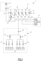
- THE figures 1 to 3 schematically represent embodiments of an electricity distribution system 10 corresponding to the invention for a domestic installation 1.
- a polyphase installation can be three-pole, comprising three phase conductors, or four-pole, comprising three phase conductors and a neutral conductor.
- connection point is a point comprising electrical connection terminals, a connection point being able to be single-phase or polyphase (e.g. three-phase) depending on the case.
- At least part of the constituents of the system 10 are housed in an electrical panel, the latter being able to be at least partially installed in an electrical panel (for example a wall panel) or in an electrical cabinet.
- the electricity distribution system 10 is configured to be powered by a main electrical power source 12, which is preferably an electrical distribution network 12 (or “grid”) and by at least one power source auxiliary 14, and to supply electricity to a plurality of loads.
- a main electrical power source 12 which is preferably an electrical distribution network 12 (or “grid”) and by at least one power source auxiliary 14, and to supply electricity to a plurality of loads.
- the number and the nature of the auxiliary electric power sources 14 can be different according to the possible embodiments.
- the electrical distribution network 12 is connected to the electrical distribution system 10 via an electrical protection device 11, for example a circuit breaker, or a fuse, or a power limiting meter.
- an electrical protection device 11 for example a circuit breaker, or a fuse, or a power limiting meter.
- auxiliary power sources 14 are available.
- one of the auxiliary power sources is a photovoltaic energy source or photovoltaic generator (e.g. photovoltaic panels) 16.
- the electrical installation 1 can comprise several photovoltaic generators.
- the installation 1 also comprises a battery electricity storage system 18, for example of the "dimmable" type (with dimmer), which can be a so-called hybrid auxiliary electric power source, i.e. which can be both a source of electricity or a load, which consumes electricity, during a recharging phase.
- a battery electricity storage system 18 for example of the "dimmable" type (with dimmer), which can be a so-called hybrid auxiliary electric power source, i.e. which can be both a source of electricity or a load, which consumes electricity, during a recharging phase.
- the installation 1 also comprises an electric vehicle or an electric vehicle charging station 20, which is a hybrid source, as well as the electricity storage 18, an electric vehicle possibly being a reversible electric storage device (“EV to grid” configuration).
- an electric vehicle or an electric vehicle charging station 20 which is a hybrid source, as well as the electricity storage 18, an electric vehicle possibly being a reversible electric storage device (“EV to grid” configuration).
- the installation 1 comprises, as a variant or in addition, one or more electric vehicles (EV) 20 adapted only to operate as a load (“grid to EV” configuration) when they are connected for recharging.
- EV electric vehicles
- Electric vehicles are among the critical (or main) loads, likely to consume significant electrical power and/or to consume high-intensity electrical currents and/or to be continuously active for long periods of time (for example more than 10 hours).
- the electrical installation 1 comprises a plurality of household electrical loads 22 (or secondary loads), for example radiators, household appliances, multimedia devices, computer equipment, lights, these examples not being limiting.
- household electrical loads 22 or secondary loads
- domestic (or secondary) loads consume less electrical power or lower current than critical loads, and their operation is generally intermittent.
- domestic loads 22 are connected, via respective protection and switching devices 24, 26, which are for example circuit breakers, to a domestic electrical panel 30.
- This domestic electrical panel 30 may, for example, be a conventional domestic limited panel. at 63 Amps (63 A).
- the domestic electrical panel 30 is connected to the electrical distribution system 10 via a switch 28, capable of providing local disconnection.
- the domestic electrical panel 30, as well as its power cable are protected by a protection device 46.
- the electrical installation 1 can also comprise several loads to be supplied with electricity, these loads possibly comprising a water heater, or a heat pump (or air conditioner, or more generally a domestic heating installation), or an air conditioner or a heating system. pool heating. These other loads to be powered can be connected to the electrical distribution system 10 via an electrical panel such as the domestic electrical panel 30 or, alternatively, connected directly to the electrical distribution system 10.
- the electrical distribution system 10 is configured to distribute the electricity supplied by the respective main and auxiliary power sources to the connected loads, according to the specific needs, while ensuring overall security, in particular by ensuring that the current conveyed does not exceed predetermined current thresholds.
- the electrical distribution system 10 may include a lightning protection device 32, connected to ground at a point 33.
- the lightning protection device 32 is connected, in the electrical distribution system 10, next to and downstream of the electrical distribution network connection, as described in more detail below with reference to the embodiments.
- the electrical distribution system 10 comprises an electrical connection device 36, arranged to distribute an electrical current in the installation, like a distributor.
- connection device 36 is arranged to be connected respectively to the electrical distribution network 12, which forms a main electrical power source, via a main switching device 38, and to each auxiliary electrical power source 34, via a device so-called associated auxiliary switching.
- Each switching device is for example a switch or a circuit breaker, configured to switch between two states respectively authorizing or preventing the flow of electric current on the electric conductors to which it is connected.
- the photovoltaic generator 16 is connected to the connection device 36 via a switching device called an auxiliary switching device 40, the electricity storage system 18 via an auxiliary switching device 42, the electric vehicle 20 is connected to the connecting device 36 via an auxiliary switching device 44.
- the domestic electrical panel 30, to which the loads 20 are connected is connected to the connection device 36 via a so-called load switching device 46.
- the distribution system 10 comprises a lightning protection device 32
- the latter is connected to the connection device 36 via an associated switching device 45, the switching device 45 being for example a circuit breaker.
- the switching device 45 being for example a circuit breaker.
- lightning protection device 32 and switching device 45 are combined.
- the lightning protection device is connected to the connection device 36 near, for example next to, the connection point of the main power source.
- minimizing the length of cables between the connection of the lightning protection device and the connection point of the main source makes it possible to maximize the effectiveness of the lightning protection device.
- the lightning protection device is connected to the connection device at a connection point 52 located next to (e.g. immediately adjacent) the connection point 58 to which the electrical distribution network 12 is connected.
- the electrical connection device 36 is formed of one or more electrical conductors or connection bars (in English "busbar"), each connection bar being associated with an electrical phase and one with the neutral line (or neutral conductor), depending on the type installation.
- some installations do not include a neutral conductor.
- the conduction bars are for example made of copper.
- each connection bar is formed by a plurality of conductive sections, electrically connected to form a conduction path.
- the electrical connection device 36 can be considered as being linear (also called “connection comb”), with several “stages”, each stage corresponding to a connection bar.
- connection comb linear
- all the elements of the electricity distribution system 10 of the installation 1, electrical power sources and loads, are connected to each connection bar, in the manner described in more detail below, the connection device 36 to make the connection on a connection stage.
- the electrical connection device 36 has a first end 53, for example the left end on the example of the figure 1 , and a second end 55, for example the right end of the figure 1 .
- first end and second end refer here to the spatial arrangement of the connecting device 36.
- the respective references 53 and 55 designate the respective opposite ends (or edges) of the connecting device 36, and not points connection (or “pin”) dedicated to electrical connections to the connection device 36.
- first end (respectively second end) connection point is a connection point close to the first end (respectively the second end), in the sense of spatial proximity.
- connection device 36 which is the first end and the left end of the connection device 36 which is the second end.
- the connecting device 36 being linear
- the first and second ends respectively designate the opposite ends of this connecting device.
- each electric power source e.g. the distribution network on the one hand and the auxiliary electric power sources on the other hand
- connection device 36 is connected to the connection device 36 via a corresponding switching device near one of the opposite ends, the loads being connected to the connection device between the respective power sources.
- Each switching device is preferably bidirectional.
- each switching device comprises a first connection point, input (or upstream) or output (or downstream) depending on the direction of the electric current, and a second connection point, output (downstream ) of the input (upstream) according to the direction of the electric current.
- the connection points are located on either side of the switching device.
- the main switching device 38 has a first connection point 56 and a second connection point 58.
- the main electrical power source e.g. the distribution network 12
- the main switchgear 38 is connected to the first connection point 56 of the main switchgear 38, the second connection point 58 of the main switching device 38 being connected to connection device 36, near the first end 53 of connection device 36.
- the main electrical power source e.g. the distribution network 12
- the connection device 36 via the switching device 38, near the first end of the connection device.
- the auxiliary power sources 14 are connected side by side, close to the second end 55 of the connection device.
- the photovoltaic generator 16 is connected to the first connection point 60 of the auxiliary switching device 40, the second connection point 62 of the auxiliary switching device 40 being connected to the connection device 36.
- the battery electricity storage system 18 is connected to the first connection point 64 of the auxiliary switchgear 42, the second connection point 66 of the auxiliary switchgear 42 being connected to the connection device 36.
- the electric vehicle 20, forming part in the illustrated embodiment of the auxiliary electric power sources 14, is connected to the first connection point 68 of the auxiliary switching device 44, the second connection point connection 70 of the auxiliary switching device 44 being connected to the connecting device 36.
- the domestic electrical panel 30, carrying the loads 22, is connected to the first connection point 72 of the load switching device 46, the second connection point 74 of the load switching device 46 being connected to the connection device 36.
- connection point located between the first end connection point, used to connect the main power source and the or each second end connection point, used to connect auxiliary power sources.
- connection points of the connection device is variable, depending on the embodiments, this number possibly being arbitrary.
- the number of loads and auxiliary electrical power sources is variable.
- the layout of the electrical distribution system 10 is such that the sources are respectively connected close to the ends of the connection device 36, respectively the distribution network close to a first end (or a first side) and the auxiliary power source(s) near the second end (or another side), opposite the first end, and the loads are all connected between the sources.
- all the auxiliary power sources 14 are connected to the connection device 36 starting from the second end 55 of the connection device 36 in the direction of the first end 53 of the connection device, one after the other, whether they are auxiliary power sources that only supply electricity (e.g. a photovoltaic generator) or hybrid auxiliary power sources (hybrid sources), which supply and consume electricity.
- auxiliary power sources that only supply electricity (e.g. a photovoltaic generator) or hybrid auxiliary power sources (hybrid sources), which supply and consume electricity.
- auxiliary power supply sources e.g. 16; 18
- hybrid auxiliary electric power sources e.g. 20
- each electrical power source eg the distribution network on the one hand and the auxiliary electrical power sources on the other hand, are connected to the device. connection via a corresponding switching device.
- connection device 36 is dimensioned (or calibrated) to support and distribute a current of electrical intensity, called maximum current threshold, equal to the maximum between the maximum electrical current supplied by the electrical distribution network (or more generally, by the source or sources connected close to the first end) and the sum of the maximum electric currents supplied by the or by the plurality of auxiliary electric sources (or more generally, by the source or sources connected close to the second end).
- maximum current threshold a current of electrical intensity
- the connecting device 36 is rated to carry 63 Amps, while being suitable to supply a total of 111 Amps to the loads connected between the respective main and auxiliary sources.
- this makes it possible to achieve a simplification and a saving of resources, for example of materials forming the connection bars of the connection device compared to a conventional distributor, which, to support a distribution of 111 Amps, must be sized accordingly.
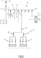
- the installation 1 further comprises an emergency generator 76, for example a generator, the connection device 36 being configured to also distribute the electricity supplied by the emergency generator 76, when the latter replaces the distribution network and forms the main alternate electricity source.
- an emergency generator 76 for example a generator
- the connection device 36 being configured to also distribute the electricity supplied by the emergency generator 76, when the latter replaces the distribution network and forms the main alternate electricity source.
- the emergency generator 76 (or emergency source) comprises an interlocking device 78 (or safety interlocking), called “interlocking device” in English, which makes it possible to interlock the main switching device and the switchgear 75, through which the emergency generator is connected to the connection device 36, so as to ensure that only one of the main power sources 12 or 76 is connected to the connection device 36 at the same time.
- the switching device 75 is for example a switch disconnector.
- the interlocking device 78 makes it possible to choose between on the one hand the emergency source 76 and on the other hand the distribution network 12 to supply the connection device 36 by the first end 53 of the connection device.
- each electrical source and each electrical load comprises a phase connector (L) and a neutral connector (N).
- electrical loads may additionally include a grounding connector (denoted PE).
- connection device such as a 35L connection bar which is a phase conductor and a 35N connection bar which is a neutral conductor.
- an additional load 21 for example a pure electricity-consuming electric vehicle, which is connected to the connection device 36 via a load switching device 43.
- the electrical connections include measurement devices, represented by the symbol "W" in the figure, capable of measuring the electrical power supplied by the electrical sources (in particular by the network 12 and by each auxiliary power source 16 , 18, 20) and/or the electrical power passing through the various switching devices.
- W measurement devices
- It may, for example, be one or more current sensors and/or voltage sensors and/or Wattmeters (W) and/or any equivalent or appropriate measuring device.
- W Wattmeters
- a first measuring device 75 is associated with the network 12
- measuring devices 79, 81 are associated with the auxiliary power sources 16, 18, and devices 83, 85 are associated with the hybrid sources or loads 20, 21 .
- These measuring devices supply current and/or voltage and/or power measurements which are supplied to an electronic control device 100, which is configured to automatically manage the distribution of the electric current between the electric loads, in particular in the case exceeding the maximum current threshold for which the connection device is calibrated, but maximizing self-consumption, and many other usage scenarios.
- the electronic control device 100 is associated with control lines each provided with a controllable switch 130, 132, such as a relay or a power semiconductor switch, which respectively make it possible to trigger the switching of the switching devices and protection 24-1 and 24-2, in order to regulate the electrical consumption of the loads 22 connected to the various branches.
- a controllable switch 130, 132 such as a relay or a power semiconductor switch, which respectively make it possible to trigger the switching of the switching devices and protection 24-1 and 24-2, in order to regulate the electrical consumption of the loads 22 connected to the various branches.
- the electronic control device comprises or is connected to a communications interface 140, which allows various communication functionalities, for example with an external network (eg Internet), which makes it possible to perform remote control functions.
- a communications interface 140 which allows various communication functionalities, for example with an external network (eg Internet), which makes it possible to perform remote control functions.
- the electronic control device 100 is configured to implement a method for managing the distribution of the electric current supplied/consumed, as a function of the current and/or voltage and/or power measurements supplied by the various measuring devices (e.g. sensors), and current or power limits imposed, in particular by the calibration of the connection device 36, and by the electrical distribution network.
- the electronic control device 100 is configured to manage power supply parameters of at least some of the electrical loads in order to reduce the current consumed and/or to manage at least some of the operating parameters of at least one part of the auxiliary electrical power sources to reduce the current delivered by these sources.
- the lightning protection device 32 comprises one or more varistors connected between the connection device 36 and a ground connection point 33 of the electrical installation connected to the connection terminal block 67.
- a varistor is connected on each electrical conductor 35L, 35N (one for phase L and one for neutral N) of connection device 36, via a switching device 45, which is preferably a switching and protection device, for example a circuit breaker.
- the emergency source 76 includes a protection device 65, connected between the switch disconnector 75 and the connection terminal block 67.
- FIG 4 is a schematic representation of a view of an assembly 90, integrating an electricity distribution system comprising a connection device 36 according to one embodiment.
- the assembly 90 is for example an electrical panel, for example a wall panel, or an electrical cabinet.
- the electrical distribution system is configured to distribute electricity from a main power source which is the distribution network 12, and auxiliary power sources 16, 18, to loads 20, 22 respectively.
- the arrows shown under the assembly 90 indicate the direction of flow of electric current forming an electrical conduction path in the electrical distribution system, in an example of operation.
- connection device 36 comprises, on the front, phase connection points L alternating with neutral connection points N, arranged at a distance chosen, for example 18mm and 36mm, suitable for the connection of corresponding switching devices, such as circuit breakers, for domestic installations.
- Assembly 90 is particularly compact.
- connection device 36 forming part of the assembly 90 comprises, on a visible face, error-proofing elements, intended to guide the installation by an electrician, by indicating in particular the order of arrangement of the connections of electrical devices (sources and loads), starting from the lightning protection device, followed by the electrical distribution network, any loads then the auxiliary electricity sources, hybrid or not.
- the polarizing elements are for example positioned at the level of the connection terminals (in English “pins”) allowing the connection to the respective connection points of the connection device 36.
- the presence of polarizers facilitates the connection of electrical devices to the "pins" of the connection device 36.
- the source 18 is a hybrid source, able to function both as an electrical power source and as an electrically consuming load.
- the distribution network 12 is a remote source where energy can be withdrawn or injected, capable of receiving the electricity produced by one or more of the auxiliary power sources when the electricity produced by these sources auxiliary power supply is not consumed by the loads connected between the main power source and the auxiliary power sources.
- connection device 36 By way of illustrative example, an electrical conduction path is shown with arrows above connection device 36.
- electrical distribution network 12 supplies 63 A.
- Household loads 22 (the reference 22 here designating the distribution panel 30 comprising several connected household loads) consume 47 A.
- auxiliary power source 16 e.g. a photovoltaic generator
- auxiliary power source 18 e.g. a battery electricity storage system
- the auxiliary electrical power sources provide 16A in this example.
- the electric vehicle 20 consumes, to charge, a current of intensity 32A, this current being supplied via the connection device 36, on the one hand by the remaining 16A of the current supplied by the electrical distribution network, and on the other hand, by the auxiliary power sources 16 and 18 jointly.
- a connection device calibrated to route 63A is capable of supplying the current consumed, without requiring the implementation of an electronic regulation of the distribution of electricity.
- the conduction path is such that the limit of 63A (maximum authorized current threshold) is not exceeded on any of the respective conductors of the connection device 36.
- figure 4 is provided by way of non-limiting example, many other electrical current distribution distributions being possible between main power source, auxiliary power sources and loads, including cases in which the hybrid sources operate as than loads and therefore consume electricity.
- connection device 36 has been described above in the case of a single-phase installation. It is understood that as a variant, in a polyphase electrical distribution system 10, for example three-phase and neutral, the configurations described are generalized for each of the electrical phases and of the neutral line.
- the connection device comprises as many conduction bars as there are phases, and if necessary by adding a neutral conductor.
- the distribution system can also be generalized in the case where the installation is polyphase without a neutral conductor.
- the generalization for a polyphase system is simple, the connection of the respective sources and loads being done by corresponding polyphase connection points.
- FIG. 5 schematically represents a view of an assembly 90' integrating an electrical distribution system according to a variant of the embodiment of the Figure 4 , integrating an electricity distribution system comprising a connection device 36′ according to one embodiment.
- the same elements of assembly 90' are designated with the same reference numerals as in the previous figures, in particular with a premium for a variation of an element.
- Figure 5 shows a three-phase embodiment with phases L1, L2, L3 and neutral line N.
- the assembly 90' is for example an electrical panel, for example a wall panel, or an electrical cabinet.
- the electrical distribution system is configured to distribute electricity from a primary power source which is the grid distribution 12, and auxiliary power sources 16 to respective loads 20, 22.
- the arrows represented under the assembly 90' indicate the direction of circulation of the electrical current (three-phase) forming an electrical conduction path in the electrical distribution system, in an example of operation.
- the electrical connection device 36' essentially corresponds to the electrical connection device 36 of the Figures 1 to 4 . Unlike the Figures 1 to 4 the connection device 36' is suitable for use in an assembly 90' for three-phase currents.
- the electrical connection device 36' can be considered as being linear (also called “connection comb"), with several "stages", each stage corresponding to a connection bar, respectively a bar for each phase L1, L2, L3 and the neutral conductor N. Therefore, the connection points are three-phase.
- connection device 36' comprises, on the front, on a first section 36a', three-phase connection points comprising electrical connection terminals of the phases L1, L2, L3 alternating, in groups, with neutral connection terminals N, arranged at a chosen distance, for example of 18mm and 36mm, suitable for the connection of corresponding switching devices 32', 38', 40', 44', 46', such as circuit breakers, for domestic installations for the protection device against lightning, the network 12 and domestic electrical loads 22.
- connection device 36′ comprises, on the front, on a second section 36b′ adjacent to the first section 36a′, connection points comprising electrical connection terminals for phases L1, L2, L3 alternating with neutral connection terminals N, arranged at a chosen distance, for example of 18mm and 36mm, suitable for the connection of the corresponding switching devices, such as circuit breakers, in particular for the load concerning the electric vehicle, i.e. the station of the load or the vehicle, and the auxiliary power sources 16.
- the circuit breaker for example for the auxiliary power source 16 or the load relating to the electric vehicle 20 are respectively connected to the three phases L1, L2, L3 and to the neutral conductor N. In one embodiment the circuit breaker or circuit breakers are not connected to all the connection points above them.
- the switching device 44' is only connected on the left to the connection terminal of the neutral conductor N and then to the connection terminals of the conductors L2, L3 and L1 of the connecting device 36'.
- the other connection terminals above the switchgear 44' remain unused.
- auxiliary switching devices 40, 44 can be connected laterally to the auxiliary switching devices 40, 44 without being connected to the connection device 36', for example an undervoltage release 44a', 40a'
- Assembly 90 is particularly compact.
- connection device 36' forming part of the assembly 90' comprises, on a visible face, misleading elements, intended to guide the installation by an electrician.
- FIG 6 schematically represents a view of a 90" assembly integrating an electrical distribution system according to a variant of the embodiment of the Figure 5 , integrating an electricity distribution system comprising a connection device 36' according to an embodiment which is identical to the connection device 36' of the figure 5 .
- the same elements of the 90" assembly are designated with the same reference numbers as on the figure 5 .
- FIG 6 shows a three-phase embodiment with phases L1, L2, L3 and neutral line N.
- the assembly 90" is for example an electrical panel, for example a wall panel, or an electrical cabinet.
- the electrical distribution system is configured to distribute electricity from a main power source which is the distribution network 12, and auxiliary power sources 16 to respective loads 20a , 20b, 22.
- the arrows represented under the assembly 90" indicate the direction of flow of the electric current (single-phase or three-phase) forming an electrical conduction path in the electrical distribution system, in an example of operation.
- the assembly includes two auxiliary switching devices 44a", 44b" for the loads 20a, 20b.
- the two switching devices are respectively single-phase and only connected to single-phase points, here the phase L2 respectively, and for the neutral conductor N.
- the loads 20a, 20b are, for example, an electric vehicle respectively.
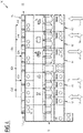
- FIG. 7 schematically represents a view of an assembly 90′′′ integrating an electrical distribution system according to a variant of the embodiment of the Figure 5 , integrating an electricity distribution system comprising a connection device 36′′′ according to one embodiment.
- the same elements of assembly 90′′′ are designated with the same reference numbers as in the previous figures, especially with three bounties for variants of an item.
- Picture 7 shows a three-phase embodiment with phases L1, L2, L3 and neutral line N.
- the assembly 90'" is for example an electrical panel, for example a wall panel, or an electrical cabinet.
- the electrical distribution system is configured to distribute electricity from a main power source which is the distribution network 12, and auxiliary power sources 16, 18 to loads 20a, 20b, 22a, 22b, 22c respectively.
- Loads 20a, 20b, 22a, 22b, 22c correspond respectively to loads 20, 22 of Figures 1 to 4 .
- Assembly 90′′′ comprises two rows, in particular an upper row 90a′′′ and a lower row 90b′′′. In another embodiment, assembly 90′′′ comprises three rows.
- the arrows represented under the assembly 90'" indicate the direction of flow of the electrical current (three-phase) forming an electrical conduction path in the electrical distribution system, in an example of operation.
- the electrical connection device 36′′′ corresponds electrically to the electrical connection device 36' of the Figure 5 Or 6 .
- the electrical connection device 36′′′ comprises several linear sections 36a′′′, 36b′′′, 36c′′′ (also called “connection comb”), with several “stages”, each stage corresponding to a connection bar, respectively a bar for each phase L1, L2, L3 and the neutral conductor N.
- connection device 36' comprises, on the front, for each section 36a′′′, 36b′′′, 36c′′′ connection points comprising electrical connection terminals of the phases L1, L2, L3 alternating, in particular in groups, with terminals phase L1, L2, L3 neutral connection terminals N.
- the connection terminals are arranged at a chosen distance, for example 18mm and 36mm, suitable for the connection of the corresponding switching devices, such as circuit breakers.
- the first section 36a′′′ and the third section 36c′′′ are arranged in the first row 90a′′′ and the second section 36b′′′ is arranged in the second row 90b′′′.
- the conductors, for example the bars, of the first section 36a′′′ are respectively electrically connected or connected to the conductors, for example bars, corresponding to the second section 36b′′′, in particular at a first end 92 or close to the first end of the second section 36b′′′.
- the conductors, for example the bars, of the third section 36c′′′ are respectively electrically connected to the conductors, for example bars, corresponding to the second section 36b′′′, in particular at a second end 93 or close to the second end of the second section 36b′′′.
- the electrical connections between sections 36a′′′, 36b′′′ and 36c′′′ are established by one or more cables 93a, 93b.
- the switching devices 32', 38' such as circuit breakers for the lightning protection device and the network 12 are connected to the first section 36a′′′.
- the switching devices 44a′′′,44b′′′,46a′′′, 46b′′′, 46c′′′ such as circuit breakers for the device for domestic electrical loads 22a, 22b, 22c, 20a, 20b are connected to the second section 36b′′′.
- the switching devices 40', 42' such as circuit breakers for the device for the auxiliary power sources 16, 18 are connected to the third section 36b′′′.
- the connection device 36′′′ forming part of the assembly 90'" comprises, on a visible face, mistake-proofing elements, intended to guide the installation by an electrician.
- Picture 7 further shows two mechanical fixing rails 94a, 94b for the various switching devices defining the two rows 90a′′′, 90b′′′.
- the embodiment of the figure 7 is electrically identical, that is to say from the point of view of the electrical circuit, to the embodiment of the preceding figures, in particular of the figure 5 And 6 .
- the second end 55 from an electrical point of view, is located on the left on the third section 36c′′′ of the connection device 36′′′ on the figure 7 .
- the switching apparatus of the auxiliary electrical power sources are connected to a second end connection point, in particular at least from an electrical point of view, of the connection device 36′′′, located near a second end 55.
- the purely electricity-consuming loads are electrically connected between the main power source 12 and the auxiliary power source(s) 16, 18 to the connection device 36′′′.
- each load switching device being connected to an intermediate connection point being electrically, that is to say from an electrical circuit point of view, between said first connection point and the or each second connection point.
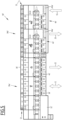
- FIG 8 schematically represents a view of an assembly 90"" integrating an electrical distribution system according to a variant of the embodiment of the Picture 7 .
- the only difference from the 90′′′ assembly of the Picture 7 is an additional electrical connection 93c between the first section 36a′′′ and the third section 36c′′′ of the connection device 36′′′.
- the conductors, for example the bars, of the third section 36c′′′ are respectively electrically connected to the conductors, for example bars, corresponding to the first section 36a′′′.
- the additional electrical connection 93c allows, when the auxiliary power sources 16, 18 produce energy exceeding the consumption of energy by the loads 20a, 20b, 22a, 22b, 22c, to directly inject this excess energy into the electrical distribution network 12, without passing through the second section 36b′′′ of the connection device 36 ′′′.
- This additional electrical connection 93c makes it possible to reduce the flow of electrical current in the second section 36b′′′ of the connection device 36′′′.
- the loads 22a, 22b, 22c 20a, 20b purely electricity consumers are electrically connected between the main power source 12 and the auxiliary power source(s) 16, 18 to the connection device 36′′′.
- FIG. 9 schematically represents a view of a 90 ⁇ ′′′ assembly integrating an electrical distribution system according to a variant of the embodiment of the Figure 8 .
- the connecting device 36 ⁇ ′′′ comprises only a first section 36a ⁇ ′′′ and a second section 36b ⁇ ′′′.
- the first section 36a ⁇ ′′′ integrates in its intermediate part the function of the additional electrical connection 93c of the connection device 36′′′ of the Picture 8 .
- the proposed distribution system is particularly compact, and its implementation is suitable for an existing installation, the work of the electrician being facilitated.
- connection device it is possible to modify, for example, the number of auxiliary power supply sources, for example by adding an additional auxiliary power supply source and removing one of the loads, provided that the additional auxiliary power source so that all pure electricity consuming loads are electrically connected between the main power source and the auxiliary power source or sources.
Landscapes
- Engineering & Computer Science (AREA)
- Power Engineering (AREA)
- Life Sciences & Earth Sciences (AREA)
- Sustainable Development (AREA)
- Sustainable Energy (AREA)
- Transportation (AREA)
- Mechanical Engineering (AREA)
- Supply And Distribution Of Alternating Current (AREA)
Applications Claiming Priority (3)
| Application Number | Priority Date | Filing Date | Title |
|---|---|---|---|
| FR2110100A FR3127648A1 (fr) | 2021-09-24 | 2021-09-24 | Système de distribution d’électricité pour une installation domestique, procédé de gestion d’un tel système de distribution d’électricité |
| EP22305033.7A EP4156438B1 (de) | 2021-09-24 | 2022-01-14 | Stromverteilungssystem für eine heimanlage mit mehreren stromquellen |
| EP22306155 | 2022-07-29 |
Publications (3)
| Publication Number | Publication Date |
|---|---|
| EP4156437A1 true EP4156437A1 (de) | 2023-03-29 |
| EP4156437C0 EP4156437C0 (de) | 2024-09-18 |
| EP4156437B1 EP4156437B1 (de) | 2024-09-18 |
Family
ID=83362474
Family Applications (1)
| Application Number | Title | Priority Date | Filing Date |
|---|---|---|---|
| EP22197840.6A Active EP4156437B1 (de) | 2021-09-24 | 2022-09-26 | Stromverteilungssystem für eine hausanlage mit mehreren elektrischen quellen |
Country Status (4)
| Country | Link |
|---|---|
| US (1) | US12456862B2 (de) |
| EP (1) | EP4156437B1 (de) |
| CN (1) | CN115864362A (de) |
| AU (1) | AU2022235584A1 (de) |
Families Citing this family (2)
| Publication number | Priority date | Publication date | Assignee | Title |
|---|---|---|---|---|
| FR3150357A1 (fr) * | 2023-06-21 | 2024-12-27 | Michaud | Système d’alimentation électrique d’un bâtiment |
| JP2025080074A (ja) * | 2023-11-13 | 2025-05-23 | トヨタ自動車株式会社 | 管理装置、制御プログラム、及び制御方法 |
Citations (4)
| Publication number | Priority date | Publication date | Assignee | Title |
|---|---|---|---|---|
| FR2432789A1 (fr) * | 1978-08-01 | 1980-02-29 | Brun Pierre | Repartiteur-limiteur de puissance pour installations electriques |
| WO2016176727A1 (en) * | 2015-05-01 | 2016-11-10 | The University Of Sydney | Operation scheduling of power generation, storage and load |
| WO2018234330A1 (fr) * | 2017-06-20 | 2018-12-27 | Latelec | Procédé et architecture d'alimentation électrique de réseau domestique embarqué |
| US20210083506A1 (en) * | 2019-09-17 | 2021-03-18 | Span.IO, Inc. | Systems and methods for managing electrical loads |
Family Cites Families (6)
| Publication number | Priority date | Publication date | Assignee | Title |
|---|---|---|---|---|
| US7692332B2 (en) * | 2007-08-30 | 2010-04-06 | Briggs And Stratton Corporation | Transfer switch |
| US8390977B2 (en) * | 2010-02-26 | 2013-03-05 | Advanced Energy Industries, Inc | Solar power inverters, including solar power inverters having surge protective devices, and associated methods |
| EP4585932A2 (de) * | 2013-04-13 | 2025-07-16 | Honey Badger International Pty Ltd | Energieerzeugungslastausgleich |
| KR20190033620A (ko) * | 2016-08-09 | 2019-03-29 | 엠에이치아이 베스타스 오프쇼어 윈드 에이/에스 | 풍력 터빈 제어 방법 및 시스템 |
| US11316471B2 (en) * | 2016-11-08 | 2022-04-26 | Tesla, Inc. | Manual transfer switch for onsite energy generation and storage systems |
| US11811261B2 (en) * | 2019-04-19 | 2023-11-07 | Sunpower Corporation | Backup load energy control system |
-
2022
- 2022-09-19 US US17/947,268 patent/US12456862B2/en active Active
- 2022-09-21 AU AU2022235584A patent/AU2022235584A1/en active Pending
- 2022-09-23 CN CN202211165922.9A patent/CN115864362A/zh active Pending
- 2022-09-26 EP EP22197840.6A patent/EP4156437B1/de active Active
Patent Citations (4)
| Publication number | Priority date | Publication date | Assignee | Title |
|---|---|---|---|---|
| FR2432789A1 (fr) * | 1978-08-01 | 1980-02-29 | Brun Pierre | Repartiteur-limiteur de puissance pour installations electriques |
| WO2016176727A1 (en) * | 2015-05-01 | 2016-11-10 | The University Of Sydney | Operation scheduling of power generation, storage and load |
| WO2018234330A1 (fr) * | 2017-06-20 | 2018-12-27 | Latelec | Procédé et architecture d'alimentation électrique de réseau domestique embarqué |
| US20210083506A1 (en) * | 2019-09-17 | 2021-03-18 | Span.IO, Inc. | Systems and methods for managing electrical loads |
Also Published As
| Publication number | Publication date |
|---|---|
| US12456862B2 (en) | 2025-10-28 |
| EP4156437C0 (de) | 2024-09-18 |
| EP4156437B1 (de) | 2024-09-18 |
| US20230096943A1 (en) | 2023-03-30 |
| CN115864362A (zh) | 2023-03-28 |
| AU2022235584A1 (en) | 2023-04-13 |
Similar Documents
| Publication | Publication Date | Title |
|---|---|---|
| JP7611906B2 (ja) | 分散型エネルギ資源デバイスで使用するためのメータ及びソケット | |
| EP4156437B1 (de) | Stromverteilungssystem für eine hausanlage mit mehreren elektrischen quellen | |
| Babasaki et al. | Development of power distribution cabinet for higher-voltage direct-current power feeding system | |
| JP7483721B2 (ja) | 分散型エネルギ資源デバイスを接続および計測するための方法およびシステム | |
| CN114144683B (zh) | 用于电连接计量设备和分布式能源设备的系统 | |
| US20110084556A1 (en) | System and apparatus for interconnecting an array of power generating assemblies | |
| US20230288451A1 (en) | Electric meter collar adaptor to divert power to distributed power generation resources | |
| EP3108725A1 (de) | Leistungsverteilerkasten mit einer eingangsleistungssammelschiene | |
| US9728972B2 (en) | Alternative energy bus bar by pass breaker, methods of use and installation | |
| WO2024010888A1 (en) | Meter for use with a distributed energy resource device | |
| US20200083837A1 (en) | Photovoltaic cabling optimization for solar trackers using a plug and play harness configuration | |
| US20200014205A1 (en) | Neutral Routing for Multiple Electrical Power Sources | |
| FR2936662A1 (fr) | Procede d'organisation d'un reseau electrique comportant plusieurs sources d'energie, repartiteur et installations | |
| EP3596791A1 (de) | System zur versorgung eines bordnetzes eines unterseebootes mit elektrischer energie | |
| EP0901143B1 (de) | Anordnung zum Zusammenbauen und Verbinden elektrischer Leistungsapparatemodule wie Schutzschalter | |
| US12015273B2 (en) | Electricity distribution system for a domestic installation comprising multiple electrical sources | |
| EP1152509B1 (de) | Elektrisches Energieübertragungs- und verteilungssystem | |
| EP4156438B1 (de) | Stromverteilungssystem für eine heimanlage mit mehreren stromquellen | |
| US20180069381A1 (en) | Alternative energy bus bar by pass breaker | |
| EP2774182A1 (de) | Sicherheitsvorrichtung für pv-modul | |
| FR2694845A1 (fr) | Tableau de distribution électrique d'étage d'immeuble. | |
| FR3038151A1 (fr) | Alimentation electrique d'une charge avec barre de distribution segmentee |
Legal Events
| Date | Code | Title | Description |
|---|---|---|---|
| PUAI | Public reference made under article 153(3) epc to a published international application that has entered the european phase |
Free format text: ORIGINAL CODE: 0009012 |
|
| STAA | Information on the status of an ep patent application or granted ep patent |
Free format text: STATUS: THE APPLICATION HAS BEEN PUBLISHED |
|
| AK | Designated contracting states |
Kind code of ref document: A1 Designated state(s): AL AT BE BG CH CY CZ DE DK EE ES FI FR GB GR HR HU IE IS IT LI LT LU LV MC MK MT NL NO PL PT RO RS SE SI SK SM TR |
|
| STAA | Information on the status of an ep patent application or granted ep patent |
Free format text: STATUS: REQUEST FOR EXAMINATION WAS MADE |
|
| 17P | Request for examination filed |
Effective date: 20230904 |
|
| RBV | Designated contracting states (corrected) |
Designated state(s): AL AT BE BG CH CY CZ DE DK EE ES FI FR GB GR HR HU IE IS IT LI LT LU LV MC MK MT NL NO PL PT RO RS SE SI SK SM TR |
|
| GRAP | Despatch of communication of intention to grant a patent |
Free format text: ORIGINAL CODE: EPIDOSNIGR1 |
|
| STAA | Information on the status of an ep patent application or granted ep patent |
Free format text: STATUS: GRANT OF PATENT IS INTENDED |
|
| INTG | Intention to grant announced |
Effective date: 20240415 |
|
| GRAS | Grant fee paid |
Free format text: ORIGINAL CODE: EPIDOSNIGR3 |
|
| GRAA | (expected) grant |
Free format text: ORIGINAL CODE: 0009210 |
|
| STAA | Information on the status of an ep patent application or granted ep patent |
Free format text: STATUS: THE PATENT HAS BEEN GRANTED |
|
| AK | Designated contracting states |
Kind code of ref document: B1 Designated state(s): AL AT BE BG CH CY CZ DE DK EE ES FI FR GB GR HR HU IE IS IT LI LT LU LV MC MK MT NL NO PL PT RO RS SE SI SK SM TR |
|
| REG | Reference to a national code |
Ref country code: GB Ref legal event code: FG4D Free format text: NOT ENGLISH |
|
| REG | Reference to a national code |
Ref country code: CH Ref legal event code: EP |
|
| REG | Reference to a national code |
Ref country code: IE Ref legal event code: FG4D Free format text: LANGUAGE OF EP DOCUMENT: FRENCH |
|
| REG | Reference to a national code |
Ref country code: DE Ref legal event code: R096 Ref document number: 602022006178 Country of ref document: DE |
|
| U01 | Request for unitary effect filed |
Effective date: 20241018 |
|
| U07 | Unitary effect registered |
Designated state(s): AT BE BG DE DK EE FI FR IT LT LU LV MT NL PT RO SE SI Effective date: 20241031 |
|
| U20 | Renewal fee for the european patent with unitary effect paid |
Year of fee payment: 3 Effective date: 20241029 |
|
| PG25 | Lapsed in a contracting state [announced via postgrant information from national office to epo] |
Ref country code: NO Free format text: LAPSE BECAUSE OF FAILURE TO SUBMIT A TRANSLATION OF THE DESCRIPTION OR TO PAY THE FEE WITHIN THE PRESCRIBED TIME-LIMIT Effective date: 20241218 |
|
| PG25 | Lapsed in a contracting state [announced via postgrant information from national office to epo] |
Ref country code: GR Free format text: LAPSE BECAUSE OF FAILURE TO SUBMIT A TRANSLATION OF THE DESCRIPTION OR TO PAY THE FEE WITHIN THE PRESCRIBED TIME-LIMIT Effective date: 20241219 |
|
| PG25 | Lapsed in a contracting state [announced via postgrant information from national office to epo] |
Ref country code: HR Free format text: LAPSE BECAUSE OF FAILURE TO SUBMIT A TRANSLATION OF THE DESCRIPTION OR TO PAY THE FEE WITHIN THE PRESCRIBED TIME-LIMIT Effective date: 20240918 |
|
| PG25 | Lapsed in a contracting state [announced via postgrant information from national office to epo] |
Ref country code: RS Free format text: LAPSE BECAUSE OF FAILURE TO SUBMIT A TRANSLATION OF THE DESCRIPTION OR TO PAY THE FEE WITHIN THE PRESCRIBED TIME-LIMIT Effective date: 20241218 |
|
| PG25 | Lapsed in a contracting state [announced via postgrant information from national office to epo] |
Ref country code: RS Free format text: LAPSE BECAUSE OF FAILURE TO SUBMIT A TRANSLATION OF THE DESCRIPTION OR TO PAY THE FEE WITHIN THE PRESCRIBED TIME-LIMIT Effective date: 20241218 Ref country code: NO Free format text: LAPSE BECAUSE OF FAILURE TO SUBMIT A TRANSLATION OF THE DESCRIPTION OR TO PAY THE FEE WITHIN THE PRESCRIBED TIME-LIMIT Effective date: 20241218 Ref country code: HR Free format text: LAPSE BECAUSE OF FAILURE TO SUBMIT A TRANSLATION OF THE DESCRIPTION OR TO PAY THE FEE WITHIN THE PRESCRIBED TIME-LIMIT Effective date: 20240918 Ref country code: GR Free format text: LAPSE BECAUSE OF FAILURE TO SUBMIT A TRANSLATION OF THE DESCRIPTION OR TO PAY THE FEE WITHIN THE PRESCRIBED TIME-LIMIT Effective date: 20241219 |
|
| PG25 | Lapsed in a contracting state [announced via postgrant information from national office to epo] |
Ref country code: IS Free format text: LAPSE BECAUSE OF FAILURE TO SUBMIT A TRANSLATION OF THE DESCRIPTION OR TO PAY THE FEE WITHIN THE PRESCRIBED TIME-LIMIT Effective date: 20250118 |
|
| PG25 | Lapsed in a contracting state [announced via postgrant information from national office to epo] |
Ref country code: SM Free format text: LAPSE BECAUSE OF FAILURE TO SUBMIT A TRANSLATION OF THE DESCRIPTION OR TO PAY THE FEE WITHIN THE PRESCRIBED TIME-LIMIT Effective date: 20240918 |
|
| PG25 | Lapsed in a contracting state [announced via postgrant information from national office to epo] |
Ref country code: ES Free format text: LAPSE BECAUSE OF FAILURE TO SUBMIT A TRANSLATION OF THE DESCRIPTION OR TO PAY THE FEE WITHIN THE PRESCRIBED TIME-LIMIT Effective date: 20240918 |
|
| PG25 | Lapsed in a contracting state [announced via postgrant information from national office to epo] |
Ref country code: PL Free format text: LAPSE BECAUSE OF FAILURE TO SUBMIT A TRANSLATION OF THE DESCRIPTION OR TO PAY THE FEE WITHIN THE PRESCRIBED TIME-LIMIT Effective date: 20240918 Ref country code: CZ Free format text: LAPSE BECAUSE OF FAILURE TO SUBMIT A TRANSLATION OF THE DESCRIPTION OR TO PAY THE FEE WITHIN THE PRESCRIBED TIME-LIMIT Effective date: 20240918 |
|
| PG25 | Lapsed in a contracting state [announced via postgrant information from national office to epo] |
Ref country code: SK Free format text: LAPSE BECAUSE OF FAILURE TO SUBMIT A TRANSLATION OF THE DESCRIPTION OR TO PAY THE FEE WITHIN THE PRESCRIBED TIME-LIMIT Effective date: 20240918 |
|
| PG25 | Lapsed in a contracting state [announced via postgrant information from national office to epo] |
Ref country code: MC Free format text: LAPSE BECAUSE OF FAILURE TO SUBMIT A TRANSLATION OF THE DESCRIPTION OR TO PAY THE FEE WITHIN THE PRESCRIBED TIME-LIMIT Effective date: 20240918 |
|
| PLBE | No opposition filed within time limit |
Free format text: ORIGINAL CODE: 0009261 |
|
| STAA | Information on the status of an ep patent application or granted ep patent |
Free format text: STATUS: NO OPPOSITION FILED WITHIN TIME LIMIT |
|
| PG25 | Lapsed in a contracting state [announced via postgrant information from national office to epo] |
Ref country code: IE Free format text: LAPSE BECAUSE OF NON-PAYMENT OF DUE FEES Effective date: 20240926 |
|
| 26N | No opposition filed |
Effective date: 20250619 |
|
| U20 | Renewal fee for the european patent with unitary effect paid |
Year of fee payment: 4 Effective date: 20250925 |
|
| PG25 | Lapsed in a contracting state [announced via postgrant information from national office to epo] |
Ref country code: CY Free format text: LAPSE BECAUSE OF FAILURE TO SUBMIT A TRANSLATION OF THE DESCRIPTION OR TO PAY THE FEE WITHIN THE PRESCRIBED TIME-LIMIT; INVALID AB INITIO Effective date: 20220926 |
|
| PG25 | Lapsed in a contracting state [announced via postgrant information from national office to epo] |
Ref country code: HU Free format text: LAPSE BECAUSE OF FAILURE TO SUBMIT A TRANSLATION OF THE DESCRIPTION OR TO PAY THE FEE WITHIN THE PRESCRIBED TIME-LIMIT; INVALID AB INITIO Effective date: 20220926 |