EP4156427A1 - Protection circuit - Google Patents
Protection circuit Download PDFInfo
- Publication number
- EP4156427A1 EP4156427A1 EP22200218.0A EP22200218A EP4156427A1 EP 4156427 A1 EP4156427 A1 EP 4156427A1 EP 22200218 A EP22200218 A EP 22200218A EP 4156427 A1 EP4156427 A1 EP 4156427A1
- Authority
- EP
- European Patent Office
- Prior art keywords
- battery pack
- protection circuit
- batteries
- heating resistor
- protection
- Prior art date
- Legal status (The legal status is an assumption and is not a legal conclusion. Google has not performed a legal analysis and makes no representation as to the accuracy of the status listed.)
- Pending
Links
- 238000010438 heat treatment Methods 0.000 claims abstract description 68
- HBBGRARXTFLTSG-UHFFFAOYSA-N Lithium ion Chemical compound [Li+] HBBGRARXTFLTSG-UHFFFAOYSA-N 0.000 description 6
- 229910001416 lithium ion Inorganic materials 0.000 description 6
- 238000004519 manufacturing process Methods 0.000 description 3
- 230000001413 cellular effect Effects 0.000 description 2
- 230000001419 dependent effect Effects 0.000 description 1
- 239000000779 smoke Substances 0.000 description 1
Images


Classifications
-
- H—ELECTRICITY
- H02—GENERATION; CONVERSION OR DISTRIBUTION OF ELECTRIC POWER
- H02J—CIRCUIT ARRANGEMENTS OR SYSTEMS FOR SUPPLYING OR DISTRIBUTING ELECTRIC POWER; SYSTEMS FOR STORING ELECTRIC ENERGY
- H02J7/00—Circuit arrangements for charging or depolarising batteries or for supplying loads from batteries
- H02J7/0029—Circuit arrangements for charging or depolarising batteries or for supplying loads from batteries with safety or protection devices or circuits
- H02J7/00308—Overvoltage protection
-
- H—ELECTRICITY
- H02—GENERATION; CONVERSION OR DISTRIBUTION OF ELECTRIC POWER
- H02H—EMERGENCY PROTECTIVE CIRCUIT ARRANGEMENTS
- H02H7/00—Emergency protective circuit arrangements specially adapted for specific types of electric machines or apparatus or for sectionalised protection of cable or line systems, and effecting automatic switching in the event of an undesired change from normal working conditions
- H02H7/18—Emergency protective circuit arrangements specially adapted for specific types of electric machines or apparatus or for sectionalised protection of cable or line systems, and effecting automatic switching in the event of an undesired change from normal working conditions for batteries; for accumulators
-
- H—ELECTRICITY
- H02—GENERATION; CONVERSION OR DISTRIBUTION OF ELECTRIC POWER
- H02J—CIRCUIT ARRANGEMENTS OR SYSTEMS FOR SUPPLYING OR DISTRIBUTING ELECTRIC POWER; SYSTEMS FOR STORING ELECTRIC ENERGY
- H02J7/00—Circuit arrangements for charging or depolarising batteries or for supplying loads from batteries
- H02J7/0013—Circuit arrangements for charging or depolarising batteries or for supplying loads from batteries acting upon several batteries simultaneously or sequentially
- H02J7/0014—Circuits for equalisation of charge between batteries
-
- H—ELECTRICITY
- H02—GENERATION; CONVERSION OR DISTRIBUTION OF ELECTRIC POWER
- H02J—CIRCUIT ARRANGEMENTS OR SYSTEMS FOR SUPPLYING OR DISTRIBUTING ELECTRIC POWER; SYSTEMS FOR STORING ELECTRIC ENERGY
- H02J7/00—Circuit arrangements for charging or depolarising batteries or for supplying loads from batteries
- H02J7/0029—Circuit arrangements for charging or depolarising batteries or for supplying loads from batteries with safety or protection devices or circuits
- H02J7/00304—Overcurrent protection
-
- H—ELECTRICITY
- H01—ELECTRIC ELEMENTS
- H01H—ELECTRIC SWITCHES; RELAYS; SELECTORS; EMERGENCY PROTECTIVE DEVICES
- H01H85/00—Protective devices in which the current flows through a part of fusible material and this current is interrupted by displacement of the fusible material when this current becomes excessive
- H01H85/02—Details
- H01H85/46—Circuit arrangements not adapted to a particular application of the protective device
- H01H2085/466—Circuit arrangements not adapted to a particular application of the protective device with remote controlled forced fusing
-
- Y—GENERAL TAGGING OF NEW TECHNOLOGICAL DEVELOPMENTS; GENERAL TAGGING OF CROSS-SECTIONAL TECHNOLOGIES SPANNING OVER SEVERAL SECTIONS OF THE IPC; TECHNICAL SUBJECTS COVERED BY FORMER USPC CROSS-REFERENCE ART COLLECTIONS [XRACs] AND DIGESTS
- Y02—TECHNOLOGIES OR APPLICATIONS FOR MITIGATION OR ADAPTATION AGAINST CLIMATE CHANGE
- Y02E—REDUCTION OF GREENHOUSE GAS [GHG] EMISSIONS, RELATED TO ENERGY GENERATION, TRANSMISSION OR DISTRIBUTION
- Y02E60/00—Enabling technologies; Technologies with a potential or indirect contribution to GHG emissions mitigation
- Y02E60/10—Energy storage using batteries
-
- Y—GENERAL TAGGING OF NEW TECHNOLOGICAL DEVELOPMENTS; GENERAL TAGGING OF CROSS-SECTIONAL TECHNOLOGIES SPANNING OVER SEVERAL SECTIONS OF THE IPC; TECHNICAL SUBJECTS COVERED BY FORMER USPC CROSS-REFERENCE ART COLLECTIONS [XRACs] AND DIGESTS
- Y02—TECHNOLOGIES OR APPLICATIONS FOR MITIGATION OR ADAPTATION AGAINST CLIMATE CHANGE
- Y02T—CLIMATE CHANGE MITIGATION TECHNOLOGIES RELATED TO TRANSPORTATION
- Y02T10/00—Road transport of goods or passengers
- Y02T10/60—Other road transportation technologies with climate change mitigation effect
- Y02T10/70—Energy storage systems for electromobility, e.g. batteries
Definitions
- the present invention relates to a protection circuit which protects a battery pack from overcurrents and overvoltages using a protection device having heating resistors and fuse elements provided on a circuit board.
- lithium-ion battery market As mobile electronic devices such as cellular telephones or notebook PCs have been widely used, the lithium-ion battery market has been expanded. These mobile electronic devices typically employ a battery pack, as its power supply, which has one to four lithium-ion batteries connected in series. Such a battery pack may ignite or cause smoke when the lithium-ion battery is overcharged (i.e., becomes under an overvoltage) during recharging, and is thus provided with a protection circuit to avoid overcharges.
- a battery pack as its power supply, which has one to four lithium-ion batteries connected in series.
- Such a battery pack may ignite or cause smoke when the lithium-ion battery is overcharged (i.e., becomes under an overvoltage) during recharging, and is thus provided with a protection circuit to avoid overcharges.
- This protection circuit is required to protect the batteries from both overcurrents and overvoltages.
- a protection circuit which includes a protection device having heating resistors and fuse elements provided on a circuit board, and a sensing device for detecting an overvoltage and switching a current flowing into the protection device.
- This protection circuit is designed such that the fuse element is melted in an overcurrent condition, while in an overvoltage condition, the sensing device allows a current to suddenly flow through the heating resistor, thereby causing the heating resistor to generate heat by which the fuse element is melted (Patent Document 1).
- Patent Document 1 Publication of Japanese Patent No. 2790433
- the voltage applied across the heating resistor of the protection device is dependent on the number of serially connected batteries that are included in the battery pack. Accordingly, to ensure that the fuse element of the protection device is melted in an overcharge condition, a lineup of protection devices has to be prepared each of which is provided with a heating resistor having an appropriate resistance value for each number of serially connected batteries.
- battery packs have a variety of voltage ratings for four or less to about ten serially connected lithium-ion batteries, this has become problematic due to an increase in costs or prices resulting from many different protection devices being produced.
- protection devices 2A and 2B each include heating resistors 3 and fuse elements 4 which are provided on a circuit board, its operable power is 10 to 20W, one battery 6 within a battery pack 5 has the maximum voltage of 4V, and a voltage sensing IC 8 and an FET 9 are provided as sensing means 7.
- the protection devices 2A and 2B have to be prepared such that the heating resistor 3 has the resistance values of Table 1 for each number of serially connected batteries 6 that are included in the battery pack 5.
- Table 1 Number of serially connected batteries Resistance value ( ⁇ ) 1 0.8 - 1.6 2 3.2 - 6.4 3 7.2 - 14 4 13 - 26 5 20 - 40 ... ... 10 80 - 160
- the protection circuit 1X of Fig. 6 is formed using a 25 ⁇ heating resistor corresponding to a battery pack 5 having four serially connected batteries.
- the voltage sensing IC 8 detects an overvoltage across the battery pack 5 resulting in a change in the gate potential of the FET 9.
- a battery pack used in a mobile electronic device operating on a large current requires the protection device to include a large-current fuse element. From this point of view, a lineup of protection devices with fuse elements of various ratings is required, which has become problematic due to an increase in costs or prices of the protection device.
- This protection circuit is intended to share a protection device regardless of the current rating of the battery pack or regardless of the number of serially connected batteries in the battery pack.
- the inventors have completed the present invention by finding the following facts in a protection circuit, which protects a battery pack having a plurality of rechargeable batteries connected in series from overcurrents and overvoltages, in an attempt to allow a voltage to be applied to heating resistors of the protection device within an operable range of the protection device when the protection circuit is activated due to an overvoltage. That is, (1) it is effective to allow the voltage of not the total number of serially connected batteries in the battery pack but a predetermined number of batteries to be applied to the heating resistor in an overvoltage condition.
- the voltage to be detected needs not always to be the voltage of the total number of serially connected batteries in the battery pack but may be the voltage of a predetermined number of serially connected batteries. It was also found that to allow the shared use of a protection device, which has a rating for normal applications, in large-current applications, the protection devices should be arranged in parallel in a plurality of stages.
- a first aspect of the present invention is to provide a protection circuit for protecting a battery pack having rechargeable batteries connected in series from overcurrents and overvoltages.
- the protection circuit comprises: a protection device having a heating resistor and a fuse element provided on a circuit board; and sensing means for detecting an overvoltage across any of the batteries in the battery pack and switching a current flowing into the heating resistor.
- the protection circuit is designed such that the fuse element is melted in an overcurrent condition, and in an overvoltage condition on any of the batteries, the sensing means switches on the current flowing into the heating resistor, thereby causing the heating resistor to generate heat and the fuse element to be melted.
- the protection circuit may be provided with a plurality of sensing means for detecting an overvoltage between different batteries.
- a second aspect of the present invention is to provide a protection circuit for protecting a battery pack having rechargeable batteries connected in series from overcurrents and overvoltages.
- the protection circuit comprises: protection devices each having a heating resistor and a fuse element provided on a circuit board; and sensing means for detecting an overvoltage across any of the batteries in the battery pack and switching a current flowing into the heating resistor.
- the plurality of protection devices are connected in parallel. In an overcurrent condition, the fuse element is melted at each protection device.
- the sensing means switches on the current flowing into the heating resistor, thereby causing a voltage across a predetermined number of the batteries in the battery pack to be applied to the heating resistor of each protection device, the heating resistor to generate heat, and the fuse element to be melted.
- the first and second aspects of the present invention are each to provide a protection circuit which protects a battery pack having rechargeable batteries connected in series from overcurrents and overvoltages.
- the protection circuit includes a protection device having heating resistors and fuse elements provided on a circuit board, and overvoltage sensing means.
- the sensing means senses an overvoltage to switch on a current flowing into the heating resistor of the protection device and apply a voltage to the heating resistor of the protection device.
- the sensed voltage is not the voltage of the total number of serially connected batteries in the battery pack but the voltage across any of the serially connected batteries.
- the heating' resistor can be shared between a protection device used in a protection circuit for a battery pack having a larger number of serially connected batteries and a protection device used in a protection circuit for a battery pack having a smaller number serially connected batteries. This makes it possible to avoid producing many different protection devices, thereby reducing the manufacturing costs of the protection circuit.
- a voltage sensing IC having a low voltage rating can detect an overvoltage on a battery pack having a high voltage rating.
- the sensed voltage is a voltage across an individual battery between any batteries, it is possible to observe a charged condition according to a variation in the characteristics of each individual battery in the battery pack.
- a plurality of sensing means can be provided to detect an overvoltage between different batteries in the battery pack.
- the protection devices are connected in parallel, and thus the fuse elements are also connected in parallel.
- the fuse element of the protection device can be shared between a protection circuit allowing a larger current to flow through the battery pack and a protection circuit allowing a smaller current to flow through the battery pack, thereby reducing the manufacturing costs of the protection device. Accordingly, the protection circuit can be manufactured at reduced costs as a whole.
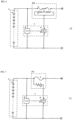
- Fig. 1 shows a protection circuit 1A according to one embodiment of the first aspect of the present invention.
- the protection circuit 1A protects a battery pack 5 having ten serially connected rechargeable batteries 6-1 to 6-10 from overcurrents and overvoltages, and includes a protection device 2A and sensing means 7.
- the protection device 2A is designed to have heating resistors 3 and fuse elements 4 provided on a circuit board, so that a current flows through the heating resistors 3 to generate heat thereby causing the fuse element 4 to be melted.
- the sensing means 7 includes a voltage sensing IC 8 and an FET 9.
- the voltage sensing IC 8 is connected so as to sense a voltage between the first battery 6-1 and the fourth battery 6-4, and output the sensed signal to the gate of the FET 9.
- the voltage sensing IC 8 suitable for sensing the serial voltage of four batteries can be used to detect an overvoltage on the battery pack 5 having ten serially connected batteries.
- the voltage sensing IC 8 is connected so as to also detect a voltage on individual batteries between the first battery 6-1 and the fourth battery 6-4. Accordingly, it is possible to detect an overvoltage on each battery even in the presence of variations in characteristics of the individual batteries accommodated in the battery pack 5 and variations in voltage on the individual batteries during charging.
- an overcurrent flowing through the battery pack 5 would cause the fuse element 4 of the protection device 2A to be melted.
- an overvoltage on the battery pack 5 would cause the FET 9 to have a gate potential above a predetermined voltage and to be thereby switched on. This in turn causes a current to suddenly flow through the drain - source of the FET 9 and thus a current to suddenly flow through the heating resistor 3 of the protection device 1A, thereby causing the heating resistor 3 to generate heat and the fuse element 4 to be melted.
- the heating resistor 3 suitable for a serial voltage across four batteries applied to the heating resistor 3 under the switched-on condition can also be used to cope with an overvoltage on the battery pack 5 having ten serially connected batteries, thereby providing the protection circuit at reduced costs.
- a voltage across as many serially connected batteries as possible is preferably applied to the heating resistor 3 under the switched-on condition.
- a voltage across two or more serially connected batteries may be applied to the heating resistor 3 in practice.
- the protection circuit 1A of Fig. 1 is provided with a resistor R between the gate and the source of the FET 9. This is because the gate potential of the FET 9 needs to be made higher to a certain extent than the source potential in order to switch on the N-channel TFT when the voltage sensing IC 8 has detected an overvoltage.
- a protection circuit 1B of Fig. 2 is designed such that a voltage sensing IC 8-1 is connected so as to sense a voltage between the first battery 6-1 and the fourth battery 6-4, and a voltage sensing IC 8-2 is also connected between the remaining battery 6-5 and the seventh battery 6-7, thus providing two voltage sensing ICs.
- the fuse element 4 of the protection device 2A is melted to thereby protect the battery pack 5 from being overcharged.
- the voltage sensing IC 8-1 raises the gate potential of an FET 9-3 causing the FET 9-3 to be switched on. This in turn causes a current to suddenly flow through the heating resistor 3 of the protection device, thereby allowing the heating resistor 3 to generate heat and the fuse element 4 to be melted.
- the voltage sensing IC 8-2 raises first the gate potential of an FET 9-1 causing a current to suddenly flow through the drain - source of the FET 9-1 and thereby lowering the gate potential of a FET 9-2. Since this FET 9-2 is a P-channel FET, the FET 9-2 is switched on due to a drop in the gate potential, causing a current to suddenly flow through the drain - source. This raises the gate potential of the FET 9-3 causing the FET 9-3 to be switched on, thus allowing a current to suddenly flow through heating resistor 3 of the protection device. The heating resistor 3 thus generates heat to melt the fuse element 4.
- diodes D-1 and D-2 are provided in order to prevent the raised gate potential of the FET 9-3 from being lowered via other parts of the circuit.
- the voltage sensing ICs 8-1 and 8-2 corresponding to, for example, three or four serially connected batteries can be used to perfectly prevent an overvoltage occurring on the battery pack having ten serially connected batteries.
- a voltage sensing IC is not available which has a high voltage rating and detects an overvoltage on the whole battery pack due to its larger number of serially connected batteries, it is possible to form a protection circuit using an existing voltage sensing IC having a low voltage rating corresponding to a battery pack having a smaller number of serially connected batteries.
- Fig. 3 is a protection circuit 1C according to one embodiment of the second aspect of the present invention directed to a large-current battery pack.
- the protection circuit 1C is provided with four protection devices 2A in parallel, which are the same as the one described above. Accordingly, even when a large current flows into the battery pack 5 in its normal conducting condition and the fuse element 4 would be melted in a case of the protection device 2A being singly provided, the protection circuit 1C allows the conduction path to be branched into four shunts in the protection device 2A, thus preventing the fuse element 4 from being melted.
- the fuse element 4 of each protection device 2A is melted.
- the fuse element of the protection device can be shared between a protection circuit allowing a larger current to flow into the battery pack and a protection circuit allowing a smaller current to flow into the battery pack, thereby reducing the manufacturing costs of the protection device.
- an overcurrent causes the fuse element 4 to be melted, for example, in a way as shown in Fig. 4 or Fig. 5 .
- a rectifier element is preferably connected to the heating resistor, and thus in the protection circuit 1C shown in Fig. 3 , a diode is connected to the protection device 2A.
- an FET may also be connected as the rectifier element to the protection device 2A.
- the protection circuit 1C is provided with three voltage sensing IC stages, and each of voltage sensing ICs 8-1, 8-2, and 8-3 employed is suitable for sensing the voltage of two to four serially connected batteries.
- Each of the voltage sensing ICs 8-1, 8-2, and 8-3 senses not only the voltage across a row of batteries respectively but also the voltage on individual batteries.
- any one of the three voltage sensing ICs 8-1, 8-2, and 8-3 senses it, causing the FET 9-3 to be switched on.
- the protection circuit according to the present invention is useful as the protection circuit for battery packs with various voltage ratings or current ratings, such as those used with cellular telephones, notebook personal computers, electric cars, or electric motorcycles.
- a protection circuit for protecting a battery pack having rechargeable batteries connected in series from overcurrents and overvoltages comprising:
- the protection circuit according to the 1 st subject comprises a plurality of sensing means for sensing an overvoltage between different batteries, wherein in an overvoltage condition on any of the batteries, the sensing means switches on a current flowing into the heating resistor.
- a voltage across a predetermined number of the batteries in the battery pack is applied to the heating resistor.
- protection circuit for protecting a battery pack having rechargeable batteries connected in series from overcurrents and overvoltages, the protection circuit comprising:
- the heating resistor is connected with a rectifier element to prevent conduction resistance from remaining via the heating resistor when an overcurrent has caused the fuse element to be melted incompletely.
Abstract
Description
- The present invention relates to a protection circuit which protects a battery pack from overcurrents and overvoltages using a protection device having heating resistors and fuse elements provided on a circuit board.
- As mobile electronic devices such as cellular telephones or notebook PCs have been widely used, the lithium-ion battery market has been expanded. These mobile electronic devices typically employ a battery pack, as its power supply, which has one to four lithium-ion batteries connected in series. Such a battery pack may ignite or cause smoke when the lithium-ion battery is overcharged (i.e., becomes under an overvoltage) during recharging, and is thus provided with a protection circuit to avoid overcharges.
- This protection circuit is required to protect the batteries from both overcurrents and overvoltages. To this end, employed is a protection circuit which includes a protection device having heating resistors and fuse elements provided on a circuit board, and a sensing device for detecting an overvoltage and switching a current flowing into the protection device. This protection circuit is designed such that the fuse element is melted in an overcurrent condition, while in an overvoltage condition, the sensing device allows a current to suddenly flow through the heating resistor, thereby causing the heating resistor to generate heat by which the fuse element is melted (Patent Document 1).
- [Patent Document 1] Publication of
Japanese Patent No. 2790433 - In recent years, as the market for mobile electronic devices that operate on a large current has been expanded, such a battery pack has come into use that operates at a rated voltage for about 10 serially connected lithium-ion batteries, which is well over previous rated voltages for four or less serially connected lithium-ion batteries.
- On the other hand, in the aforementioned battery pack protection circuit, the voltage applied across the heating resistor of the protection device is dependent on the number of serially connected batteries that are included in the battery pack. Accordingly, to ensure that the fuse element of the protection device is melted in an overcharge condition, a lineup of protection devices has to be prepared each of which is provided with a heating resistor having an appropriate resistance value for each number of serially connected batteries. However, now that battery packs have a variety of voltage ratings for four or less to about ten serially connected lithium-ion batteries, this has become problematic due to an increase in costs or prices resulting from many different protection devices being produced.
- For example, in a
protection circuit 1X ofFig. 6 and aprotection circuit 1Y ofFig. 7 , suppose thatprotection devices heating resistors 3 and fuse elements 4 which are provided on a circuit board, its operable power is 10 to 20W, onebattery 6 within abattery pack 5 has the maximum voltage of 4V, and avoltage sensing IC 8 and anFET 9 are provided as sensing means 7. In this case, theprotection devices heating resistor 3 has the resistance values of Table 1 for each number of serially connectedbatteries 6 that are included in thebattery pack 5.[Table 1] Number of serially connected batteries Resistance value (Ω) 1 0.8 - 1.6 2 3.2 - 6.4 3 7.2 - 14 4 13 - 26 5 20 - 40 ... ... 10 80 - 160 - Suppose that in a
battery pack 5 having ten serially connected batteries, theprotection circuit 1X ofFig. 6 is formed using a 25 Ω heating resistor corresponding to abattery pack 5 having four serially connected batteries. In this case, in an overcharge condition, the voltage sensingIC 8 detects an overvoltage across thebattery pack 5 resulting in a change in the gate potential of theFET 9. The power consumption W at theheating resistor 3 when a large current flows through theheating resistor 3 is given by the following equation:
heating resistor 3 will be burned out. - As can be seen from the foregoing, it is necessary to use such a
heating resistor 3 of theprotection devices battery pack 5. - On the other hand, a battery pack used in a mobile electronic device operating on a large current requires the protection device to include a large-current fuse element. From this point of view, a lineup of protection devices with fuse elements of various ratings is required, which has become problematic due to an increase in costs or prices of the protection device.
- It is therefore an object of the present invention to provide a protection circuit which protects a battery pack from overcurrents and overvoltages using sensing means and a protection device having heating resistors and fuse elements provided on a circuit board. This protection circuit is intended to share a protection device regardless of the current rating of the battery pack or regardless of the number of serially connected batteries in the battery pack.
- The inventors have completed the present invention by finding the following facts in a protection circuit, which protects a battery pack having a plurality of rechargeable batteries connected in series from overcurrents and overvoltages, in an attempt to allow a voltage to be applied to heating resistors of the protection device within an operable range of the protection device when the protection circuit is activated due to an overvoltage. That is, (1) it is effective to allow the voltage of not the total number of serially connected batteries in the battery pack but a predetermined number of batteries to be applied to the heating resistor in an overvoltage condition. (2) In detecting an overvoltage using the sensing means, the voltage to be detected needs not always to be the voltage of the total number of serially connected batteries in the battery pack but may be the voltage of a predetermined number of serially connected batteries. It was also found that to allow the shared use of a protection device, which has a rating for normal applications, in large-current applications, the protection devices should be arranged in parallel in a plurality of stages.
- That is, a first aspect of the present invention is to provide a protection circuit for protecting a battery pack having rechargeable batteries connected in series from overcurrents and overvoltages. The protection circuit comprises: a protection device having a heating resistor and a fuse element provided on a circuit board; and sensing means for detecting an overvoltage across any of the batteries in the battery pack and switching a current flowing into the heating resistor. The protection circuit is designed such that the fuse element is melted in an overcurrent condition, and in an overvoltage condition on any of the batteries, the sensing means switches on the current flowing into the heating resistor, thereby causing the heating resistor to generate heat and the fuse element to be melted. In particular, the protection circuit may be provided with a plurality of sensing means for detecting an overvoltage between different batteries.
- Furthermore, a second aspect of the present invention is to provide a protection circuit for protecting a battery pack having rechargeable batteries connected in series from overcurrents and overvoltages. The protection circuit comprises: protection devices each having a heating resistor and a fuse element provided on a circuit board; and sensing means for detecting an overvoltage across any of the batteries in the battery pack and switching a current flowing into the heating resistor. The plurality of protection devices are connected in parallel. In an overcurrent condition, the fuse element is melted at each protection device. Additionally, in an overvoltage condition on any of the batteries, the sensing means switches on the current flowing into the heating resistor, thereby causing a voltage across a predetermined number of the batteries in the battery pack to be applied to the heating resistor of each protection device, the heating resistor to generate heat, and the fuse element to be melted.
- The first and second aspects of the present invention are each to provide a protection circuit which protects a battery pack having rechargeable batteries connected in series from overcurrents and overvoltages. The protection circuit includes a protection device having heating resistors and fuse elements provided on a circuit board, and overvoltage sensing means.
- In the first one of these protection circuits, the sensing means senses an overvoltage to switch on a current flowing into the heating resistor of the protection device and apply a voltage to the heating resistor of the protection device. At this time, the sensed voltage is not the voltage of the total number of serially connected batteries in the battery pack but the voltage across any of the serially connected batteries. For this reason, the heating' resistor can be shared between a protection device used in a protection circuit for a battery pack having a larger number of serially connected batteries and a protection device used in a protection circuit for a battery pack having a smaller number serially connected batteries. This makes it possible to avoid producing many different protection devices, thereby reducing the manufacturing costs of the protection circuit. Furthermore, according to this protection circuit, a voltage sensing IC having a low voltage rating can detect an overvoltage on a battery pack having a high voltage rating. Here, assuming that the sensed voltage is a voltage across an individual battery between any batteries, it is possible to observe a charged condition according to a variation in the characteristics of each individual battery in the battery pack. On the other hand, in this protection circuit, a plurality of sensing means can be provided to detect an overvoltage between different batteries in the battery pack. In this case, even when such a voltage sensing IC is not available which has a high voltage rating and detects an overvoltage on the whole battery pack due to its larger number of serially connected batteries, it is possible to form a protection circuit using an existing voltage sensing IC having a low voltage rating corresponding to a battery pack having a smaller number of serially connected batteries.
- In the second one of these protection circuits, the protection devices are connected in parallel, and thus the fuse elements are also connected in parallel. For this reason, the fuse element of the protection device can be shared between a protection circuit allowing a larger current to flow through the battery pack and a protection circuit allowing a smaller current to flow through the battery pack, thereby reducing the manufacturing costs of the protection device. Accordingly, the protection circuit can be manufactured at reduced costs as a whole.
-
-
Fig. 1 shows a protection circuit according to a different aspect of the present invention; -
Fig. 2 shows a protection circuit according to a different aspect of the present invention; -
Fig. 3 shows a protection circuit according to a different aspect of the present invention; -
Fig. 4 is an explanatory view showing a conduction path where a fuse element is melted in a circuit having protection devices arranged in parallel; -
Fig. 5 is an explanatory view showing a conduction path where a fuse element is melted in a circuit having protection devices arranged in parallel; -
Fig. 6 is an explanatory view showing a problem with a conventional protection circuit; and -
Fig. 7 is an explanatory view showing a problem with a conventional protection circuit. -
- 1X, 1Y: Conventional protection circuit
- 1A, 1B, 1C: Protection circuit according to an embodiment
- 2A, 2B: Protection device
- 3: Heating resistor
- 4: Fuse element
- 5: Battery pack
- 6, 6-1 to 6-10: Battery
- 7: Sensing means
- 8, 8-1, 8-2, 8-3: Voltage sensing IC
- 9, 9-1, 9-2, 9-3: FET
- Now, the present invention will be described below in more detail with reference to the accompanying drawings. In each of the drawings, like symbols indicate the same or equivalent components.
-
Fig. 1 shows aprotection circuit 1A according to one embodiment of the first aspect of the present invention. Theprotection circuit 1A protects abattery pack 5 having ten serially connected rechargeable batteries 6-1 to 6-10 from overcurrents and overvoltages, and includes aprotection device 2A and sensing means 7. - As described in the publication of
Japanese Patent No. 2790433 Japanese Patent Laid-Open Publication No. 2000-285778 protection device 2A is designed to haveheating resistors 3 and fuse elements 4 provided on a circuit board, so that a current flows through theheating resistors 3 to generate heat thereby causing the fuse element 4 to be melted. - The sensing means 7 includes a
voltage sensing IC 8 and anFET 9. Thevoltage sensing IC 8 is connected so as to sense a voltage between the first battery 6-1 and the fourth battery 6-4, and output the sensed signal to the gate of theFET 9. By connecting thevoltage sensing IC 8 in this manner, thevoltage sensing IC 8 suitable for sensing the serial voltage of four batteries can be used to detect an overvoltage on thebattery pack 5 having ten serially connected batteries. In particular, in thisprotection circuit 1B, thevoltage sensing IC 8 is connected so as to also detect a voltage on individual batteries between the first battery 6-1 and the fourth battery 6-4. Accordingly, it is possible to detect an overvoltage on each battery even in the presence of variations in characteristics of the individual batteries accommodated in thebattery pack 5 and variations in voltage on the individual batteries during charging. - In the
protection circuit 1A, an overcurrent flowing through thebattery pack 5 would cause the fuse element 4 of theprotection device 2A to be melted. Furthermore, an overvoltage on thebattery pack 5 would cause theFET 9 to have a gate potential above a predetermined voltage and to be thereby switched on. This in turn causes a current to suddenly flow through the drain - source of theFET 9 and thus a current to suddenly flow through theheating resistor 3 of theprotection device 1A, thereby causing theheating resistor 3 to generate heat and the fuse element 4 to be melted. - Here, since the source terminal of the
FET 9 is connected between the battery 6-4 and the battery 6-5 in thebattery pack 5, a voltage across theheating resistor 3 under the switched-on condition is not the voltage across thebattery pack 5 but a serial voltage across four batteries that is defined by the position of this connection. Thus, according to this protection circuit, theheating resistor 3 suitable for a serial voltage across four batteries applied to theheating resistor 3 under the switched-on condition can also be used to cope with an overvoltage on thebattery pack 5 having ten serially connected batteries, thereby providing the protection circuit at reduced costs. - In consideration of troubles caused by a short circuit between batteries, a voltage across as many serially connected batteries as possible is preferably applied to the
heating resistor 3 under the switched-on condition. However, since there is an extremely low possibility of a short circuit between batteries, a voltage across two or more serially connected batteries may be applied to theheating resistor 3 in practice. - Furthermore, the
protection circuit 1A ofFig. 1 is provided with a resistor R between the gate and the source of theFET 9. This is because the gate potential of theFET 9 needs to be made higher to a certain extent than the source potential in order to switch on the N-channel TFT when thevoltage sensing IC 8 has detected an overvoltage. - Like the
protection circuit 1A ofFig. 1 , aprotection circuit 1B ofFig. 2 is designed such that a voltage sensing IC 8-1 is connected so as to sense a voltage between the first battery 6-1 and the fourth battery 6-4, and a voltage sensing IC 8-2 is also connected between the remaining battery 6-5 and the seventh battery 6-7, thus providing two voltage sensing ICs. When either the voltage sensing IC 8-1 or 8-2 has sensed an overvoltage, the fuse element 4 of theprotection device 2A is melted to thereby protect thebattery pack 5 from being overcharged. - That is, when there occurs an overvoltage on any one battery between the first battery 6-1 and the fourth battery 6-4, the voltage sensing IC 8-1 raises the gate potential of an FET 9-3 causing the FET 9-3 to be switched on. This in turn causes a current to suddenly flow through the
heating resistor 3 of the protection device, thereby allowing theheating resistor 3 to generate heat and the fuse element 4 to be melted. - On the other hand, when there occurs an overvoltage on any one battery between the fifth battery 6-5 and the seventh battery 6-7, the voltage sensing IC 8-2 raises first the gate potential of an FET 9-1 causing a current to suddenly flow through the drain - source of the FET 9-1 and thereby lowering the gate potential of a FET 9-2. Since this FET 9-2 is a P-channel FET, the FET 9-2 is switched on due to a drop in the gate potential, causing a current to suddenly flow through the drain - source. This raises the gate potential of the FET 9-3 causing the FET 9-3 to be switched on, thus allowing a current to suddenly flow through
heating resistor 3 of the protection device. Theheating resistor 3 thus generates heat to melt the fuse element 4. Here, diodes D-1 and D-2 are provided in order to prevent the raised gate potential of the FET 9-3 from being lowered via other parts of the circuit. - Thus, according to the
protection circuit 1B, the voltage sensing ICs 8-1 and 8-2 corresponding to, for example, three or four serially connected batteries can be used to perfectly prevent an overvoltage occurring on the battery pack having ten serially connected batteries. In other words, even when such a voltage sensing IC is not available which has a high voltage rating and detects an overvoltage on the whole battery pack due to its larger number of serially connected batteries, it is possible to form a protection circuit using an existing voltage sensing IC having a low voltage rating corresponding to a battery pack having a smaller number of serially connected batteries. -
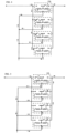
Fig. 3 is aprotection circuit 1C according to one embodiment of the second aspect of the present invention directed to a large-current battery pack. Theprotection circuit 1C is provided with fourprotection devices 2A in parallel, which are the same as the one described above. Accordingly, even when a large current flows into thebattery pack 5 in its normal conducting condition and the fuse element 4 would be melted in a case of theprotection device 2A being singly provided, theprotection circuit 1C allows the conduction path to be branched into four shunts in theprotection device 2A, thus preventing the fuse element 4 from being melted. - On the other hand, in an overcurrent condition, the fuse element 4 of each
protection device 2A is melted. Thus, according to theprotection circuit 1C, the fuse element of the protection device can be shared between a protection circuit allowing a larger current to flow into the battery pack and a protection circuit allowing a smaller current to flow into the battery pack, thereby reducing the manufacturing costs of the protection device. - Suppose that in a circuit having protection devices arranged in parallel, an overcurrent causes the fuse element 4 to be melted, for example, in a way as shown in
Fig. 4 or Fig. 5 . In this case, there will remain conduction paths in the circuit as shown by the arrows even after the fuse element 4 has been melted. In order to prevent such a conduction path from remaining after the fuse element 4 has been melted, a rectifier element is preferably connected to the heating resistor, and thus in theprotection circuit 1C shown inFig. 3 , a diode is connected to theprotection device 2A. Alternatively, an FET may also be connected as the rectifier element to theprotection device 2A. - Furthermore, pursuant to the two voltage sensing IC stages provided in the
protection circuit 1B ofFig. 2 , theprotection circuit 1C is provided with three voltage sensing IC stages, and each of voltage sensing ICs 8-1, 8-2, and 8-3 employed is suitable for sensing the voltage of two to four serially connected batteries. Each of the voltage sensing ICs 8-1, 8-2, and 8-3 senses not only the voltage across a row of batteries respectively but also the voltage on individual batteries. Thus, according to theprotection circuit 1C, even when any one of the ten batteries 6-1 to 6-10 is overcharged, any one of the three voltage sensing ICs 8-1, 8-2, and 8-3 senses it, causing the FET 9-3 to be switched on. This in turn allows a serial voltage of the four batteries 6-1 to 6-4 to be applied to eachheating resistor 3 of theprotection device 2A, thereby causing theheating resistor 3 to generate heat and the fuse element 4 to be melted. As described above, according to theprotection circuit 1C, it is possible to form a protection circuit good for a battery pack having ten serially connected batteries, by using the voltage sensing IC and the protection device which are suitable for sensing the voltage across two. to four serially connected batteries. - The protection circuit according to the present invention is useful as the protection circuit for battery packs with various voltage ratings or current ratings, such as those used with cellular telephones, notebook personal computers, electric cars, or electric motorcycles.
- As evident from the above, the following subjects form part of the content of the present disclosure.
- According to a 1st subject, there is provided a protection circuit for protecting a battery pack having rechargeable batteries connected in series from overcurrents and overvoltages,
the protection circuit comprising: - a protection device having a heating resistor and a fuse element provided on a circuit board; and
- sensing means for detecting an overvoltage across any of the batteries in the battery pack and switching a current flowing into the heating resistor, wherein
- the fuse element is melted in an overcurrent condition, and in an overvoltage condition on any of the batteries, the sensing means switches on the current flowing into the heating resistor, thereby causing the heating resistor to generate heat and the fuse element to be melted.
- According to a 2nd subject, the protection circuit according to the 1st subject comprises a plurality of sensing means for sensing an overvoltage between different batteries, wherein in an overvoltage condition on any of the batteries, the sensing means switches on a current flowing into the heating resistor.
- According to a 3rd subject, in the protection circuit according to the 1st or 2nd subjects, in the overvoltage condition on any of the batteries, a voltage across a predetermined number of the batteries in the battery pack is applied to the heating resistor.
- According to a 4th subject, there is provided protection circuit for protecting a battery pack having rechargeable batteries connected in series from overcurrents and overvoltages,
the protection circuit comprising: - protection devices each having a heating resistor and a fuse element provided on a circuit board; and
- sensing means for detecting an overvoltage across any of the batteries in the battery pack and switching a current flowing into the heating resistor, wherein:
- the plurality of protection devices are connected in parallel;
- in an overcurrent condition, the fuse element is melted at each protection device; and
- in an overvoltage condition on any of the batteries, the sensing means switches on the current flowing into the heating resistor, thereby causing a voltage across a predetermined number of the batteries in the battery pack to be applied to the heating resistor of each protection device, the heating resistor to generate heat, and the fuse element to be melted.
- According to a 5th subject, in the protection circuit according to the 4th subject, the heating resistor is connected with a rectifier element to prevent conduction resistance from remaining via the heating resistor when an overcurrent has caused the fuse element to be melted incompletely.
Claims (2)
- A protection circuit for protecting a battery pack having rechargeable batteries connected in series from overcurrents and overvoltages,the protection circuit comprising:protection devices each having a heating resistor and a fuse element provided on a circuit board; andsensing means for detecting an overvoltage across a predetermined number out of the batteries in the battery pack and each individual battery of said predetermined number out of the batteries in the battery pack and switching a current flowing into the heating resistor,wherein:the plurality of protection devices are connected in parallel;the fuse element is configured to be melted at each protection device in an overcurrent condition; anda rectifier element is provided between each of the protection devices and the sensing means.
- The protection circuit according to claim 1, wherein the heating resistors of the protection devices are connected with the rectifier element.
Applications Claiming Priority (5)
| Application Number | Priority Date | Filing Date | Title |
|---|---|---|---|
| JP2004291756A JP4207877B2 (en) | 2004-10-04 | 2004-10-04 | Protection circuit |
| EP05778471.2A EP1798833B1 (en) | 2004-10-04 | 2005-09-06 | Protection circuit |
| EP20203270.2A EP3823123B1 (en) | 2004-10-04 | 2005-09-06 | Protection circuit |
| EP19163089.6A EP3525309B1 (en) | 2004-10-04 | 2005-09-06 | Protection circuit |
| PCT/JP2005/016281 WO2006038412A1 (en) | 2004-10-04 | 2005-09-06 | Protection circuit |
Related Parent Applications (3)
| Application Number | Title | Priority Date | Filing Date |
|---|---|---|---|
| EP05778471.2A Division EP1798833B1 (en) | 2004-10-04 | 2005-09-06 | Protection circuit |
| EP19163089.6A Division EP3525309B1 (en) | 2004-10-04 | 2005-09-06 | Protection circuit |
| EP20203270.2A Division EP3823123B1 (en) | 2004-10-04 | 2005-09-06 | Protection circuit |
Publications (1)
| Publication Number | Publication Date |
|---|---|
| EP4156427A1 true EP4156427A1 (en) | 2023-03-29 |
Family
ID=36142494
Family Applications (4)
| Application Number | Title | Priority Date | Filing Date |
|---|---|---|---|
| EP20203270.2A Active EP3823123B1 (en) | 2004-10-04 | 2005-09-06 | Protection circuit |
| EP22200218.0A Pending EP4156427A1 (en) | 2004-10-04 | 2005-09-06 | Protection circuit |
| EP05778471.2A Active EP1798833B1 (en) | 2004-10-04 | 2005-09-06 | Protection circuit |
| EP19163089.6A Active EP3525309B1 (en) | 2004-10-04 | 2005-09-06 | Protection circuit |
Family Applications Before (1)
| Application Number | Title | Priority Date | Filing Date |
|---|---|---|---|
| EP20203270.2A Active EP3823123B1 (en) | 2004-10-04 | 2005-09-06 | Protection circuit |
Family Applications After (2)
| Application Number | Title | Priority Date | Filing Date |
|---|---|---|---|
| EP05778471.2A Active EP1798833B1 (en) | 2004-10-04 | 2005-09-06 | Protection circuit |
| EP19163089.6A Active EP3525309B1 (en) | 2004-10-04 | 2005-09-06 | Protection circuit |
Country Status (8)
| Country | Link |
|---|---|
| US (1) | US7679330B2 (en) |
| EP (4) | EP3823123B1 (en) |
| JP (1) | JP4207877B2 (en) |
| KR (1) | KR101201569B1 (en) |
| CN (1) | CN101040415B (en) |
| HK (1) | HK1110705A1 (en) |
| TW (1) | TW200625362A (en) |
| WO (1) | WO2006038412A1 (en) |
Families Citing this family (43)
| Publication number | Priority date | Publication date | Assignee | Title |
|---|---|---|---|---|
| KR100807063B1 (en) | 2006-05-24 | 2008-02-25 | 삼성에스디아이 주식회사 | Battery pack |
| TWI343683B (en) | 2007-06-28 | 2011-06-11 | Delta Electronics Inc | Circuit and method for protecting energy storage device |
| KR100938080B1 (en) | 2007-09-28 | 2010-01-21 | 삼성에스디아이 주식회사 | Safety circuit and battery pack using the same |
| KR101081078B1 (en) * | 2008-11-14 | 2011-11-07 | 주식회사 엘지화학 | Apparatus and method protecting battery pack by detecting destruction of sense resistor in battery pack |
| KR101016825B1 (en) * | 2009-02-24 | 2011-02-21 | 삼성에스디아이 주식회사 | Battery pack and protecting method thereof |
| US9129769B2 (en) | 2009-09-04 | 2015-09-08 | Cyntec Co., Ltd. | Protective device |
| US8472158B2 (en) | 2009-09-04 | 2013-06-25 | Cyntec Co., Ltd. | Protective device |
| TWI452592B (en) * | 2010-04-16 | 2014-09-11 | Cyntec Co Ltd | Protective device and electronic device |
| TWI456617B (en) * | 2010-05-14 | 2014-10-11 | Cyntec Co Ltd | Protective device and electronic device |
| US9025295B2 (en) | 2009-09-04 | 2015-05-05 | Cyntec Co., Ltd. | Protective device and protective module |
| US8531263B2 (en) * | 2009-11-24 | 2013-09-10 | Littelfuse, Inc. | Circuit protection device |
| KR101093888B1 (en) | 2009-12-28 | 2011-12-13 | 삼성에스디아이 주식회사 | Battery pack and method of detecting line open thereof |
| JP5415318B2 (en) * | 2010-02-19 | 2014-02-12 | デクセリアルズ株式会社 | Protection circuit, battery control device, and battery pack |
| US20110304943A1 (en) * | 2010-06-10 | 2011-12-15 | Bruce Barton | Relocatable surge suppression or surge protection device |
| CN102652268A (en) * | 2010-08-31 | 2012-08-29 | 松下电器产业株式会社 | Battery power supply device and battery power supply system |
| JP5764911B2 (en) | 2010-11-01 | 2015-08-19 | ソニー株式会社 | Battery pack and power consuming equipment |
| JP5683372B2 (en) * | 2011-04-27 | 2015-03-11 | デクセリアルズ株式会社 | Charge / discharge control device, battery pack, electric device, and charge / discharge control method |
| TWI488208B (en) * | 2011-08-18 | 2015-06-11 | Ind Tech Res Inst | Protection component and protection device using the same |
| CN102354593A (en) * | 2011-09-29 | 2012-02-15 | 贵州天义汽车电器有限公司 | Speed regulation resistor for automobile fan |
| US9337671B2 (en) | 2011-12-19 | 2016-05-10 | Dexerials Corporation | Protective element, protective element fabrication method, and battery module in which protective element is embedded |
| KR101440888B1 (en) | 2011-12-27 | 2014-09-17 | 삼성에스디아이 주식회사 | Battery protection circuit |
| JP5759911B2 (en) * | 2012-01-30 | 2015-08-05 | Jx日鉱日石エネルギー株式会社 | Solar cell unit and solar cell module |
| US9608430B2 (en) * | 2013-04-11 | 2017-03-28 | International Business Machines Corporation | Battery circuit fault protection in uninterruptable power sources |
| JP6292802B2 (en) * | 2013-09-06 | 2018-03-14 | デクセリアルズ株式会社 | Battery circuit, protection circuit |
| KR101658863B1 (en) * | 2013-10-07 | 2016-09-22 | 주식회사 엘지화학 | Apparatus and method for having algorithm of malfunction prevention |
| JP6202992B2 (en) * | 2013-11-01 | 2017-09-27 | デクセリアルズ株式会社 | Protective circuit, battery circuit, protective element, and driving method of protective element |
| WO2015107629A1 (en) * | 2014-01-15 | 2015-07-23 | デクセリアルズ株式会社 | Protection circuit and protection circuit control method |
| JP6173925B2 (en) | 2014-01-15 | 2017-08-02 | 株式会社マキタ | Electric work equipment |
| JP2016067165A (en) * | 2014-09-25 | 2016-04-28 | エスアイアイ・セミコンダクタ株式会社 | Charge discharge controller and battery device |
| CN104935024B (en) | 2015-03-06 | 2017-03-29 | 广东欧珀移动通信有限公司 | Rechargeable battery component and terminal device |
| CN105470596A (en) * | 2015-06-30 | 2016-04-06 | 巫立斌 | Method for reducing power consumption of lithium battery protection board |
| CN106468896B (en) * | 2015-08-21 | 2019-09-06 | 浙江正泰电器股份有限公司 | Combined protector |
| JP6510674B2 (en) | 2015-11-25 | 2019-05-08 | ヤマハ発動機株式会社 | Lithium-ion secondary battery protection circuit and battery pack |
| TWI597754B (en) * | 2016-05-20 | 2017-09-01 | 聚鼎科技股份有限公司 | Protection device and circuit protection apparatus containing the same |
| JP6544805B2 (en) * | 2016-10-05 | 2019-07-17 | ショット日本株式会社 | Protection circuit |
| KR102390002B1 (en) | 2018-08-31 | 2022-04-22 | 주식회사 엘지에너지솔루션 | System and method for controlling a fuse using detecting a failure mode |
| KR102646285B1 (en) | 2018-12-21 | 2024-03-13 | 에스케이온 주식회사 | Battery system |
| EP3709393A1 (en) * | 2019-03-11 | 2020-09-16 | Hilti Aktiengesellschaft | Battery fuse |
| TWI699026B (en) * | 2019-06-10 | 2020-07-11 | 聚鼎科技股份有限公司 | Secondary battery and protection device thereof |
| JP7377069B2 (en) | 2019-11-08 | 2023-11-09 | デクセリアルズ株式会社 | Protection circuit, battery pack and protection circuit operation method |
| JP7377070B2 (en) | 2019-11-08 | 2023-11-09 | デクセリアルズ株式会社 | Protection circuit, battery pack and protection circuit operation method |
| TWI797641B (en) * | 2020-06-17 | 2023-04-01 | 日商肖特(日本)股份有限公司 | protect the circuit |
| JPWO2022181600A1 (en) * | 2021-02-24 | 2022-09-01 |
Citations (5)
| Publication number | Priority date | Publication date | Assignee | Title |
|---|---|---|---|---|
| JP2790433B2 (en) | 1993-08-31 | 1998-08-27 | ソニー株式会社 | Protection element and circuit board |
| JP2000285778A (en) | 1999-03-31 | 2000-10-13 | Sony Chem Corp | Protective element |
| US6208117B1 (en) * | 1999-07-30 | 2001-03-27 | Fujitsu Limited | Battery pack and electronic apparatus using the same |
| EP1289096A2 (en) * | 2001-08-29 | 2003-03-05 | Hitachi, Ltd. | Battery apparatus for controlling plural batteries and control method of plural batteries |
| JP2004193000A (en) * | 2002-12-12 | 2004-07-08 | Sony Chem Corp | Secondary battery device |
Family Cites Families (5)
| Publication number | Priority date | Publication date | Assignee | Title |
|---|---|---|---|---|
| JP3500000B2 (en) | 1996-03-22 | 2004-02-23 | 三洋電機株式会社 | Rechargeable battery charge control method |
| JP3982078B2 (en) * | 1998-08-26 | 2007-09-26 | ソニー株式会社 | Battery protection circuit and electronic device |
| JP2002315202A (en) | 2001-04-17 | 2002-10-25 | Nec Tokin Tochigi Ltd | Battery pack for multiple and series connection |
| JP2003111268A (en) * | 2001-09-28 | 2003-04-11 | Mitsubishi Materials Corp | Secondary battery with overcharge protection circuit |
| DE10158494C1 (en) | 2001-11-29 | 2003-08-07 | Dialog Semiconductor Gmbh | Charge / discharge protection circuit |
-
2004
- 2004-10-04 JP JP2004291756A patent/JP4207877B2/en active Active
-
2005
- 2005-09-06 EP EP20203270.2A patent/EP3823123B1/en active Active
- 2005-09-06 EP EP22200218.0A patent/EP4156427A1/en active Pending
- 2005-09-06 EP EP05778471.2A patent/EP1798833B1/en active Active
- 2005-09-06 CN CN2005800336030A patent/CN101040415B/en active Active
- 2005-09-06 EP EP19163089.6A patent/EP3525309B1/en active Active
- 2005-09-06 KR KR1020077007630A patent/KR101201569B1/en active IP Right Grant
- 2005-09-06 WO PCT/JP2005/016281 patent/WO2006038412A1/en active Application Filing
- 2005-09-06 US US10/598,924 patent/US7679330B2/en active Active
- 2005-09-12 TW TW094131275A patent/TW200625362A/en unknown
-
2008
- 2008-01-22 HK HK08100822.6A patent/HK1110705A1/en unknown
Patent Citations (6)
| Publication number | Priority date | Publication date | Assignee | Title |
|---|---|---|---|---|
| JP2790433B2 (en) | 1993-08-31 | 1998-08-27 | ソニー株式会社 | Protection element and circuit board |
| JP2000285778A (en) | 1999-03-31 | 2000-10-13 | Sony Chem Corp | Protective element |
| US6208117B1 (en) * | 1999-07-30 | 2001-03-27 | Fujitsu Limited | Battery pack and electronic apparatus using the same |
| EP1289096A2 (en) * | 2001-08-29 | 2003-03-05 | Hitachi, Ltd. | Battery apparatus for controlling plural batteries and control method of plural batteries |
| JP2004193000A (en) * | 2002-12-12 | 2004-07-08 | Sony Chem Corp | Secondary battery device |
| US7333315B2 (en) * | 2002-12-12 | 2008-02-19 | Sony Chemical & Information Device Corporation | Secondary battery devices |
Also Published As
| Publication number | Publication date |
|---|---|
| HK1110705A1 (en) | 2008-07-18 |
| CN101040415A (en) | 2007-09-19 |
| CN101040415B (en) | 2011-05-25 |
| JP4207877B2 (en) | 2009-01-14 |
| WO2006038412A1 (en) | 2006-04-13 |
| TW200625362A (en) | 2006-07-16 |
| KR20070098987A (en) | 2007-10-08 |
| EP1798833A1 (en) | 2007-06-20 |
| US20070159138A1 (en) | 2007-07-12 |
| KR101201569B1 (en) | 2012-11-14 |
| EP3823123A1 (en) | 2021-05-19 |
| EP3525309B1 (en) | 2020-11-04 |
| EP3823123B1 (en) | 2022-11-09 |
| EP1798833B1 (en) | 2019-04-17 |
| US7679330B2 (en) | 2010-03-16 |
| TWI296122B (en) | 2008-04-21 |
| EP1798833A4 (en) | 2017-09-06 |
| EP3525309A1 (en) | 2019-08-14 |
| JP2006109596A (en) | 2006-04-20 |
Similar Documents
| Publication | Publication Date | Title |
|---|---|---|
| EP3823123B1 (en) | Protection circuit | |
| US7638977B2 (en) | Battery pack protective circuit for detecting overcharge or wire disconnect | |
| JP4254227B2 (en) | battery pack | |
| US9048677B2 (en) | Semiconductor device for protecting secondary battery, battery pack, and electronic device using same | |
| JP4186052B2 (en) | Battery pack with charge control function | |
| JP4771096B2 (en) | Protection circuit | |
| KR101182430B1 (en) | Battery pack | |
| US7541777B2 (en) | Battery protection circuit | |
| JP2002540756A (en) | Apparatus and method for protection of rechargeable devices | |
| US20110299209A1 (en) | Battery protection module | |
| US20080192399A1 (en) | Secondary battery apparatus and a protection circuit thereof | |
| KR20190018378A (en) | Battery protection circuit and battery pack including same | |
| KR101729730B1 (en) | Apparatus for protecting battery from overcurrent | |
| JP2002281660A (en) | Protective device of battery pack | |
| KR20070076627A (en) | Protection circuit for battery | |
| KR20120045891A (en) | Packaging layout structure of battery protection circuits | |
| JP2009077610A (en) | Charge/discharge protection circuit and battery pack | |
| KR20170062326A (en) | Apparatus for battery protection | |
| CN219372065U (en) | Battery protection circuit and terminal | |
| JP2004355837A (en) | Packed cell having overcurrent protection circuit | |
| KR101724025B1 (en) | Battery protection apparatus for breaking power at high temperature or high current based on metal-insulator transition | |
| KR20170062763A (en) | Battery protection device using one-chip | |
| JP4333907B2 (en) | Overdischarge prevention circuit for lithium ion secondary battery | |
| JP2003189462A (en) | Protective circuit for secondary battery | |
| KR101088896B1 (en) | Electronic fuse device for battery |
Legal Events
| Date | Code | Title | Description |
|---|---|---|---|
| PUAI | Public reference made under article 153(3) epc to a published international application that has entered the european phase |
Free format text: ORIGINAL CODE: 0009012 |
|
| STAA | Information on the status of an ep patent application or granted ep patent |
Free format text: STATUS: THE APPLICATION HAS BEEN PUBLISHED |
|
| AC | Divisional application: reference to earlier application |
Ref document number: 1798833 Country of ref document: EP Kind code of ref document: P Ref document number: 3525309 Country of ref document: EP Kind code of ref document: P Ref document number: 3823123 Country of ref document: EP Kind code of ref document: P |
|
| AK | Designated contracting states |
Kind code of ref document: A1 Designated state(s): AT BE BG CH CY CZ DE DK EE ES FI FR GB GR HU IE IS IT LI LT LU LV MC NL PL PT RO SE SI SK TR |
|
| STAA | Information on the status of an ep patent application or granted ep patent |
Free format text: STATUS: REQUEST FOR EXAMINATION WAS MADE |
|
| 17P | Request for examination filed |
Effective date: 20230929 |
|
| RBV | Designated contracting states (corrected) |
Designated state(s): AT BE BG CH CY CZ DE DK EE ES FI FR GB GR HU IE IS IT LI LT LU LV MC NL PL PT RO SE SI SK TR |