EP4156350A1 - Fuel cell system and method for controlling fuel cell system - Google Patents
Fuel cell system and method for controlling fuel cell system Download PDFInfo
- Publication number
- EP4156350A1 EP4156350A1 EP20936088.2A EP20936088A EP4156350A1 EP 4156350 A1 EP4156350 A1 EP 4156350A1 EP 20936088 A EP20936088 A EP 20936088A EP 4156350 A1 EP4156350 A1 EP 4156350A1
- Authority
- EP
- European Patent Office
- Prior art keywords
- fuel cell
- temperature
- fuel
- oxidant gas
- discharged
- Prior art date
- Legal status (The legal status is an assumption and is not a legal conclusion. Google has not performed a legal analysis and makes no representation as to the accuracy of the status listed.)
- Pending
Links
- 239000000446 fuel Substances 0.000 title claims abstract description 519
- 238000000034 method Methods 0.000 title claims abstract description 32
- 239000007789 gas Substances 0.000 claims abstract description 176
- 239000007800 oxidant agent Substances 0.000 claims abstract description 165
- 230000001590 oxidative effect Effects 0.000 claims abstract description 165
- 238000002407 reforming Methods 0.000 claims abstract description 147
- 239000003054 catalyst Substances 0.000 claims abstract description 35
- 150000002430 hydrocarbons Chemical class 0.000 claims abstract description 15
- 229930195733 hydrocarbon Natural products 0.000 claims abstract description 14
- 239000004215 Carbon black (E152) Substances 0.000 claims abstract description 13
- 239000001257 hydrogen Substances 0.000 claims abstract description 10
- 229910052739 hydrogen Inorganic materials 0.000 claims abstract description 10
- UFHFLCQGNIYNRP-UHFFFAOYSA-N Hydrogen Chemical compound [H][H] UFHFLCQGNIYNRP-UHFFFAOYSA-N 0.000 claims abstract description 9
- 238000007254 oxidation reaction Methods 0.000 claims description 100
- 230000003647 oxidation Effects 0.000 claims description 96
- 230000020169 heat generation Effects 0.000 claims description 40
- 238000010248 power generation Methods 0.000 description 41
- CURLTUGMZLYLDI-UHFFFAOYSA-N Carbon dioxide Chemical compound O=C=O CURLTUGMZLYLDI-UHFFFAOYSA-N 0.000 description 26
- 238000000629 steam reforming Methods 0.000 description 19
- QVGXLLKOCUKJST-UHFFFAOYSA-N atomic oxygen Chemical compound [O] QVGXLLKOCUKJST-UHFFFAOYSA-N 0.000 description 15
- 229910002092 carbon dioxide Inorganic materials 0.000 description 15
- 239000001569 carbon dioxide Substances 0.000 description 15
- 239000001301 oxygen Substances 0.000 description 15
- 229910052760 oxygen Inorganic materials 0.000 description 15
- VNWKTOKETHGBQD-UHFFFAOYSA-N methane Chemical compound C VNWKTOKETHGBQD-UHFFFAOYSA-N 0.000 description 14
- 238000010586 diagram Methods 0.000 description 12
- 238000006243 chemical reaction Methods 0.000 description 11
- 238000012986 modification Methods 0.000 description 10
- 230000004048 modification Effects 0.000 description 10
- 230000007423 decrease Effects 0.000 description 9
- 230000001276 controlling effect Effects 0.000 description 7
- 238000002485 combustion reaction Methods 0.000 description 5
- 239000003792 electrolyte Substances 0.000 description 5
- 239000007787 solid Substances 0.000 description 5
- XLYOFNOQVPJJNP-UHFFFAOYSA-N water Substances O XLYOFNOQVPJJNP-UHFFFAOYSA-N 0.000 description 5
- 238000010438 heat treatment Methods 0.000 description 4
- 238000006057 reforming reaction Methods 0.000 description 4
- 238000011144 upstream manufacturing Methods 0.000 description 4
- OKKJLVBELUTLKV-UHFFFAOYSA-N Methanol Chemical compound OC OKKJLVBELUTLKV-UHFFFAOYSA-N 0.000 description 3
- 230000002596 correlated effect Effects 0.000 description 3
- 239000002828 fuel tank Substances 0.000 description 3
- 238000002156 mixing Methods 0.000 description 3
- OKTJSMMVPCPJKN-UHFFFAOYSA-N Carbon Chemical compound [C] OKTJSMMVPCPJKN-UHFFFAOYSA-N 0.000 description 2
- 229910052799 carbon Inorganic materials 0.000 description 2
- 230000000694 effects Effects 0.000 description 2
- 238000003487 electrochemical reaction Methods 0.000 description 2
- XLYOFNOQVPJJNP-ZSJDYOACSA-N heavy water Substances [2H]O[2H] XLYOFNOQVPJJNP-ZSJDYOACSA-N 0.000 description 2
- 238000001556 precipitation Methods 0.000 description 2
- 230000000644 propagated effect Effects 0.000 description 2
- 238000010792 warming Methods 0.000 description 2
- LFQSCWFLJHTTHZ-UHFFFAOYSA-N Ethanol Chemical compound CCO LFQSCWFLJHTTHZ-UHFFFAOYSA-N 0.000 description 1
- 125000000217 alkyl group Chemical group 0.000 description 1
- 238000013459 approach Methods 0.000 description 1
- 238000007084 catalytic combustion reaction Methods 0.000 description 1
- 239000000470 constituent Substances 0.000 description 1
- 230000000875 corresponding effect Effects 0.000 description 1
- 238000001514 detection method Methods 0.000 description 1
- 150000002431 hydrogen Chemical class 0.000 description 1
- 239000011261 inert gas Substances 0.000 description 1
- 239000007788 liquid Substances 0.000 description 1
- 239000000203 mixture Substances 0.000 description 1
- 238000002360 preparation method Methods 0.000 description 1
- 230000001737 promoting effect Effects 0.000 description 1
- 239000010409 thin film Substances 0.000 description 1
- 239000002699 waste material Substances 0.000 description 1
Images


Classifications
-
- H—ELECTRICITY
- H01—ELECTRIC ELEMENTS
- H01M—PROCESSES OR MEANS, e.g. BATTERIES, FOR THE DIRECT CONVERSION OF CHEMICAL ENERGY INTO ELECTRICAL ENERGY
- H01M8/00—Fuel cells; Manufacture thereof
- H01M8/04—Auxiliary arrangements, e.g. for control of pressure or for circulation of fluids
- H01M8/04007—Auxiliary arrangements, e.g. for control of pressure or for circulation of fluids related to heat exchange
- H01M8/04014—Heat exchange using gaseous fluids; Heat exchange by combustion of reactants
-
- H—ELECTRICITY
- H01—ELECTRIC ELEMENTS
- H01M—PROCESSES OR MEANS, e.g. BATTERIES, FOR THE DIRECT CONVERSION OF CHEMICAL ENERGY INTO ELECTRICAL ENERGY
- H01M8/00—Fuel cells; Manufacture thereof
- H01M8/06—Combination of fuel cells with means for production of reactants or for treatment of residues
- H01M8/0606—Combination of fuel cells with means for production of reactants or for treatment of residues with means for production of gaseous reactants
- H01M8/0612—Combination of fuel cells with means for production of reactants or for treatment of residues with means for production of gaseous reactants from carbon-containing material
- H01M8/0637—Direct internal reforming at the anode of the fuel cell
-
- H—ELECTRICITY
- H01—ELECTRIC ELEMENTS
- H01M—PROCESSES OR MEANS, e.g. BATTERIES, FOR THE DIRECT CONVERSION OF CHEMICAL ENERGY INTO ELECTRICAL ENERGY
- H01M8/00—Fuel cells; Manufacture thereof
- H01M8/04—Auxiliary arrangements, e.g. for control of pressure or for circulation of fluids
- H01M8/04298—Processes for controlling fuel cells or fuel cell systems
- H01M8/04313—Processes for controlling fuel cells or fuel cell systems characterised by the detection or assessment of variables; characterised by the detection or assessment of failure or abnormal function
- H01M8/0432—Temperature; Ambient temperature
- H01M8/0435—Temperature; Ambient temperature of cathode exhausts
-
- H—ELECTRICITY
- H01—ELECTRIC ELEMENTS
- H01M—PROCESSES OR MEANS, e.g. BATTERIES, FOR THE DIRECT CONVERSION OF CHEMICAL ENERGY INTO ELECTRICAL ENERGY
- H01M8/00—Fuel cells; Manufacture thereof
- H01M8/04—Auxiliary arrangements, e.g. for control of pressure or for circulation of fluids
- H01M8/04298—Processes for controlling fuel cells or fuel cell systems
- H01M8/04694—Processes for controlling fuel cells or fuel cell systems characterised by variables to be controlled
- H01M8/04746—Pressure; Flow
- H01M8/04753—Pressure; Flow of fuel cell reactants
-
- H—ELECTRICITY
- H01—ELECTRIC ELEMENTS
- H01M—PROCESSES OR MEANS, e.g. BATTERIES, FOR THE DIRECT CONVERSION OF CHEMICAL ENERGY INTO ELECTRICAL ENERGY
- H01M8/00—Fuel cells; Manufacture thereof
- H01M8/06—Combination of fuel cells with means for production of reactants or for treatment of residues
- H01M8/0606—Combination of fuel cells with means for production of reactants or for treatment of residues with means for production of gaseous reactants
- H01M8/0612—Combination of fuel cells with means for production of reactants or for treatment of residues with means for production of gaseous reactants from carbon-containing material
- H01M8/0618—Reforming processes, e.g. autothermal, partial oxidation or steam reforming
-
- Y—GENERAL TAGGING OF NEW TECHNOLOGICAL DEVELOPMENTS; GENERAL TAGGING OF CROSS-SECTIONAL TECHNOLOGIES SPANNING OVER SEVERAL SECTIONS OF THE IPC; TECHNICAL SUBJECTS COVERED BY FORMER USPC CROSS-REFERENCE ART COLLECTIONS [XRACs] AND DIGESTS
- Y02—TECHNOLOGIES OR APPLICATIONS FOR MITIGATION OR ADAPTATION AGAINST CLIMATE CHANGE
- Y02E—REDUCTION OF GREENHOUSE GAS [GHG] EMISSIONS, RELATED TO ENERGY GENERATION, TRANSMISSION OR DISTRIBUTION
- Y02E60/00—Enabling technologies; Technologies with a potential or indirect contribution to GHG emissions mitigation
- Y02E60/30—Hydrogen technology
- Y02E60/50—Fuel cells
Definitions
- the present invention relates to a fuel cell system and a control method for the fuel cell system, which includes a fuel cell.
- JP 2017-117550 A discloses a method of controlling a temperature distribution throughout a fuel cell to be uniform by detecting a temperature of a central portion of a cell stack where the temperature is highest.
- the temperature distribution throughout the fuel cell is made uniform by supplying an inert gas to the central portion of the cell stack where the temperature is highest, in order to decrease the temperature of the central portion of the cell stack.
- JP 2017-117550 A is based on a premise that the central portion of the cell stack has the highest temperature, but depending on a configuration and/or an operation scene of the fuel cell, the central portion of the cell stack may not always have the highest temperature as compared with other portions.
- a reforming catalyst configured to reform a fuel (hereinafter, referred to as a reforming catalyst) inside a cell stack
- a temperature control when a temperature control is performed based on a temperature of the central portion of the cell stack, a temperature may exceed an upper limit of heat resistance in a part of the cell stack.
- An object of the present invention is to provide a fuel cell system and a control method configured to perform a temperature control within a range not exceeding an upper limit of heat resistance in a fuel cell when a cell stack with a reforming catalyst is included.
- the fuel cell system includes a fuel cell including a cell stack configured to have a reforming catalyst for generating hydrogen from hydrocarbon, a first flow path configured to supply a fuel containing hydrocarbon to the cell stack, and a second flow path configured to supply an oxidant gas to the cell stack such that the oxidant gas flows oppositely or orthogonally to the fuel.
- the control method for the fuel cell system including: detecting a temperature of a discharged oxidant gas that is the oxidant gas discharged from the second flow path; and performing a temperature control of the fuel cell based on the temperature of the discharged oxidant gas.
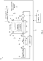
- FIG. 1 is a block diagram showing a configuration of a fuel cell system 10 according to a first embodiment.
- the fuel cell system 10 includes a power generation device 11 and a controller 12.
- the power generation device 11 is a device that generates a power using a fuel cell 20, and includes, in addition to the fuel cell 20, a fuel flow rate adjustment device 31, an air flow rate adjustment device 33, an oxidant gas supply device 41, a heat exchanger 43, a combustor 51, a temperature sensor 60, and the like.
- the controller 12 is a control device that integrally controls the power generation device 11 and units constituting the power generation device 11.
- the fuel cell 20 includes a fuel cell (hereinafter, simply referred to as a cell) configured to generate a power by an electrochemical reaction using a fuel and an oxidant gas.
- the fuel cell 20 includes a cell stack 21 which is formed by a single cell or by stacked multiple cells and configured to generate a required power as a whole.
- the cell stack 21 includes a reforming catalyst inside thereof (hereinafter, referred to as an internal reforming catalyst).
- the internal reforming catalyst 22 reforms a fuel supplied to the fuel cell 20 (hereinafter, referred to as a raw fuel) by generating or promoting a specific chemical reaction, and generates a fuel (hereinafter, referred to as a reformed fuel (an anode gas)) that can be directly used for power generation from the raw fuel.
- the raw fuel is, for example, a fuel containing hydrocarbon group, such as an alkyl group, as its main component, and is specifically a hydrocarbon such as methane or an alcohol such as methanol.
- the internal reforming catalyst 22 generates the reformed fuel containing hydrogen used for the power generation from the raw fuel containing hydrocarbons. Therefore, the fuel cell 20 is a so-called direct internal reforming type, and in principle, the fuel cell 20 can generate a power by itself by supplying an unreformed raw fuel or an incompletely reformed raw fuel without requiring a separate reformer.
- Fuel reforming that can be performed by the cell stack 21 includes, for example, partial oxidation reforming (POX), steam reforming (SR), and carbon dioxide reforming.
- POX partial oxidation reforming
- SR steam reforming
- carbon dioxide reforming The internal reforming catalyst 22 contributes to a part or all of these reforming reactions.
- Partial oxidation reforming is a reforming reaction in which the raw fuel is partially oxidized by mixing oxygen (O 2 ) with the raw fuel in order to obtain the reformed fuel.
- O 2 oxygen
- Partial oxidation reforming proceeds mainly by partial oxidation reaction shown in the following (1).
- partial oxidation reforming for example, complete combustion (complete oxidation) shown in the following (2) occurs and proceeds in an initial stage, except for a case where partial oxidation reforming is occurred on some very exceptional catalysts. Therefore, in partial oxidation reforming, water (H 2 O) is also generated in addition to hydrogen (H 2 ). Both partial oxidation reaction of (1) and complete combustion of (2) are exothermic reactions.
- partial oxidation reforming is an exothermic reaction.
- partial oxidation reforming is a reaction that consumes oxygen. Therefore, partial oxidation reforming does not occur uniformly throughout the cell stack 21, but occurs relatively more in an upstream portion of a fuel flow path (a first flow path 23 to be described later) and relatively less in a downstream portion of the fuel flow path where oxygen has been consumed. This is because oxygen is abundant in the upstream portion, but is consumed sequentially by the progress of partial oxidation reforming, and contained oxygen is relatively low in the downstream portion. In this way, since the occurrence of partial oxidation reforming varies gradually along the fuel flow path in the cell stack 21, a large temperature gradient may be generated in the cell stack 21.
- Steam reforming is a reforming reaction in which the raw fuel is partially oxidized by reacting the raw fuel or the reformed fuel with water (steam) in order to obtain the reformed fuel.
- steam reforming proceeds mainly by an oxidation reaction shown in the following (3) or (4).
- Steam reforming may proceed using newly supplied water or water generated by partial oxidation reforming (particularly, complete combustion).
- the cell stack 21 performs steam reforming using water generated by partial oxidation reforming.
- Steam reforming is an endothermic reaction.
- Carbon dioxide reforming is a reforming reaction in which the raw fuel or the reformed fuel is partially oxidized to obtain the reformed fuel, by reacting the raw fuel, or the reformed fuel reformed by partial oxidation reforming or steam reforming, with carbon dioxide (CO 2 ).
- carbon dioxide CO 2
- carbon dioxide reforming proceeds mainly by partial oxidation reaction shown in the following (5).
- Carbon dioxide reforming may proceed by using newly supplied carbon dioxide or carbon dioxide generated by partial oxidation reforming (particularly, complete combustion) or steam reforming.
- the cell stack 21 performs carbon dioxide reforming using carbon dioxide generated by partial oxidation reforming and/or steam reforming.
- Carbon dioxide reforming is an endothermic reaction. CH 4 + CO 2 ⁇ 2CO + 2H 2 ... (5)
- the fuel cell 20 is, for example, a solid oxide fuel cell (SOFC).
- SOFC solid oxide fuel cell
- the cell stack 21 includes the first flow path 23 which is a flow path of a raw fuel and/or a reformed fuel (hereinafter, simply referred to as a fuel unless a distinction is necessary), a second flow path 24 which is a flow path of an oxidant gas, and an electrolyte (not shown) made of a solid oxide.
- the cell stack 21 has a structure in which the first flow path 23 and the second flow path 24 are adjacent to each other via the electrolyte. Therefore, the internal reforming catalyst 22 is provided in the first flow path 23 which is the flow path of the fuel.
- an electrode configured to act as a negative electrode is provided on a surface of the electrolyte in the first flow path 23, and an electrode (hereinafter, referred to as a cathode) configured to act as a positive electrode is provided on a surface of the electrolyte in the second flow path 24.
- the internal reforming catalyst 22 is separate from the anode, but a part or all of the anode may act as the internal reforming catalyst 22.
- the internal reforming catalyst 22 is provided substantially uniformly throughout the cell stack 21. That is, the internal reforming catalyst 22 is provided not only in a specific portion of the first flow path 23, and the raw fuel may be reformed substantially at any portion of the first flow path 23 in the cell stack 21.
- the fuel cell 20 includes an anode inlet A1, an anode outlet A2, a cathode inlet C3, and a cathode outlet C4.
- the anode inlet A1 is an end portion on an upstream side of the first flow path 23, and is an inlet of the raw fuel to the fuel cell 20. Therefore, the anode inlet A1 is connected to the fuel flow rate adjustment device 31 via a fuel supply path 32.
- the anode outlet A2 is an end portion on a downstream side of the first flow path 23, and discharges the used fuel, a gas generated by the power generation, and the like (hereinafter, referred to as a discharged fuel (an anode off-gas)) to an outside of the fuel cell 20.
- the anode outlet A2 is connected to the combustor 51 via a fuel discharge path 34.
- the cathode inlet C3 is an end portion on an upstream side of the second flow path 24, and is an inlet of the oxidant gas to the fuel cell 20.
- the cathode inlet C3 is connected to the oxidant gas supply device 41 via an oxidant gas supply path 42.
- the cathode outlet C4 is an end portion on a downstream side of the second flow path 24, and discharges the used oxidant gas for the power generation, a gas generated by the power generation, and the like (hereinafter, referred to as a discharged oxidant gas (a cathode off-gas)) to the outside of the fuel cell 20.
- the cathode outlet C4 is connected to the combustor 51 via an oxidant gas discharge path 44.
- the fuel cell 20 supplies a power to an apparatus, a device, or the like connected to the fuel cell 20.
- the apparatus, the device, or the like connected to the fuel cell 20 is, for example, a storage battery, or a motor used as a drive source of an electric vehicle.
- the fuel cell 20 is connected to a storage battery connected to a motor for driving an electric vehicle. Therefore, the fuel cell 20 acts as an energy source that indirectly drives the electric vehicle.
- the fuel flow rate adjustment device 31 is a device (a fuel supply device) that supplies the raw fuel to the fuel cell 20, and is a device that adjusts a flow rate of the raw fuel to be supplied to the fuel cell 20.
- the fuel flow rate adjustment device 31 is connected to the anode inlet A1 via the fuel supply path 32.
- the fuel flow rate adjustment device 31 includes a fuel tank and an injector.
- the fuel tank stores the raw fuel, for example, in a liquid state.
- the injector injects the raw fuel from the fuel tank into the fuel supply path 32. Accordingly, the fuel flow rate adjustment device 31 supplies the raw fuel to the fuel cell 20.
- a timing at which the fuel flow rate adjustment device 31 supplies the raw fuel to the fuel cell 20, a supply amount of the raw fuel, and the like are controlled by the controller 12.
- the fuel flow rate adjustment device 31 may include a heat exchanger or the like as necessary. In this case, the fuel flow rate adjustment device 31 can adjust a temperature, a phase, a pressure, and the like of the raw fuel by heating, heat exchange, or the like. In the present embodiment, the fuel flow rate adjustment device 31 vaporizes the raw fuel and supplies the vaporized raw fuel to the fuel cell 20.
- the air flow rate adjustment device 33 is connected to the fuel supply path 32, and is a device (an air supply device) that mixes the raw fuel to be supplied to the fuel cell 20 by the fuel flow rate adjustment device 31 with air as necessary, and is a device that adjusts a flow rate of the air to be mixed with the raw fuel.
- the air flow rate adjustment device 33 is, for example, an air blower.
- a purpose of mixing the raw fuel with the air by the air flow rate adjustment device 33 is to occur partial oxidation reforming in the cell stack 21 or to promote partial oxidation reforming occurred in the cell stack 21 by including oxygen in the raw fuel. Therefore, it is sufficient for the air flow rate adjustment device 33 to be able to mix the oxygen with the raw fuel as necessary.
- the air flow rate adjustment device 33 may be configured to mix the raw fuel with oxygen alone, a gas other than air containing oxygen, air whose constituent components, temperature, and the like are adjusted, or the like, instead of natural air.
- a timing at which the air flow rate adjustment device 33 mixes the raw fuel with the air, an amount of air to be mixed with the raw fuel, and the like are controlled by the controller 12.
- the oxidant gas supply device 41 is a device that supplies the oxidant gas to the fuel cell 20, and is connected to the cathode inlet C3 via the oxidant gas supply path 42.
- the oxidant gas is air containing oxygen used for the power generation by the fuel cell 20. That is, in the present embodiment, the oxidant gas supply device 41 is an air blower.
- the heat exchanger 43 is provided in the oxidant gas supply path 42, and heats the oxidant gas by heat exchange. Therefore, the heat exchanger 43 supplies the heated oxidant gas to the fuel cell 20.
- the heat exchange for heating the oxidant gas is performed with a gas discharged from the combustor 51 (hereinafter, referred to as a discharged gas).
- the discharged fuel is supplied from the fuel cell 20 to the combustor 51 via the fuel discharge path 34.
- the discharged oxidant gas is supplied from the fuel cell 20 to the combustor 51 via the oxidant gas discharge path 44.
- the combustor 51 combusts the discharged fuel and the discharged oxidant gas by, for example, catalytic combustion.
- the discharged gas generated as a result of the combustion is discharged from a gas discharge path 52 to an outside of the fuel cell system 10 via the heat exchanger 43. Therefore, heat generated by the electrochemical reaction in the fuel cell 20, the generation of the discharged gas, and the like is used for heating the oxidant gas in the oxidant gas supply path 42 by the heat exchange in the heat exchanger 43.
- the temperature sensor 60 is provided in the oxidant gas discharge path 44.
- the temperature sensor 60 detects a temperature of the discharged oxidant gas that is the oxidant gas discharged from the fuel cell 20, more specifically, the oxidant gas discharged from the second flow path 24.
- the temperature sensor 60 inputs the detected temperature of the discharged oxidant gas to the controller 12.
- the controller 12 performs a temperature control of the fuel cell 20 based on the temperature of the discharged oxidant gas detected by the temperature sensor 60. Particularly, in the present embodiment, the controller 12 performs the temperature control of the fuel cell 20 with heat generated by partial oxidation reforming in the cell stack 21. A specific method by which the controller 12 performs the temperature control of the fuel cell 20 will be described in detail later.
- the controller 12 is a computer or a microcomputer implemented by using a processor such as a CPU and a GPU, a memory, and the like.
- the controller 12 may be implemented as a dedicated computer for controlling the fuel cell system 10, or may be implemented as a part of a computer for controlling other devices, systems, or the like.
- a vehicle controller that controls driving and the like of the electric vehicle may be made to act as the controller 12 of the fuel cell system 10.
- the controller 12 may be implemented as a server type computer that controls the power generation device 11 by communicating with the power generation device 11.
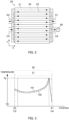
- FIG. 2 is an explanatory diagram showing a flow path of a fuel and a flow path of an oxidant gas in the cell stack 21 in the present embodiment.
- the first flow path 23 is a flow path that supplies the fuel to the cell stack 21.
- the second flow path 24 is a flow path that supplies the oxidant gas to the cell stack 21 such that the oxidant gas flows oppositely to the fuel.
- the first flow path 23 and the second flow path 24 are parallel in shape as a flow path, but a direction in which the fuel flows through the first flow path 23 and a direction in which the oxidant gas flows through the second flow path 24 are opposite to each other.
- the first flow path 23 and the second flow path 24 are reverse parallel or antiparallel, and the fuel and the oxidant gas form a so-called counter flow.
- the second flow path 24 may be a flow path that supplies the oxidant gas to the cell stack 21 such that the oxidant gas flows orthogonally to the fuel.
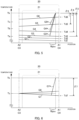
- FIG. 3 is a schematic graph showing a temperature distribution in the fuel cell 20 when partial oxidation reforming is performed.
- FIG. 3 shows the temperature distribution in the fuel cell 20 formed when the cell stack 21 reaches or exceeds a temperature at which partial oxidation reforming may be occurred as a whole and partial oxidation reforming occurs on the cell stack 21.
- the temperature at which partial oxidation reforming may be occurred is, for example, about 300°C or higher.
- a horizontal axis represents a position along the first flow path 23 and the second flow path 24.
- the cells constituting the cell stack 21 are stacked in a direction of a vertical axis.
- a graph 101 indicated by a solid line represents a temperature of the fuel in the fuel cell 20, and a graph 102 indicated by a broken line represents a temperature of the oxidant gas.
- the temperatures of the fuel and the oxidant gas in the cell stack 21 may be considered to be substantially the same as a temperature of the fuel cell 20.
- partial oxidation reforming forms a temperature distribution in the fuel cell 20 in which the temperature generally decreases from the anode inlet A1 to the anode outlet A2.
- the fuel cell 20 has a highest temperature Tp at a predetermined position (the anode inlet A1 or a position in the vicinity of the anode inlet A1) biased toward the anode inlet A1 side, rather than a position of a central portion of the fuel cell 20.
- a temperature distribution of the oxidant gas follows the temperature distribution formed by partial oxidation reforming as described above, and is substantially the same temperature distribution at least in the cell stack 21. This is because the fuel and the oxidant gas flow in the cell stack 21 via the electrolyte, which is a thin film, in an integrated manner on front and back sides, and thus have substantially the same temperature due to mutual heat exchange. Therefore, the discharged oxidant gas discharged from the cathode outlet C4 is discharged at a temperature substantially equal to a maximum temperature in the temperature distribution formed by partial oxidation reforming, or at a temperature correlated with the maximum temperature in the temperature distribution formed by partial oxidation reforming.
- the temperature correlated with the maximum temperature refers to a temperature by which a maximum temperature of the fuel cell 20 can be calculated or estimated based on a certain relationship of the temperature with the maximum temperature of the fuel cell 20.
- the temperature sensor 60 detects the temperature of the discharged oxidant gas. As a result, the temperature sensor 60 detects the maximum temperature of the fuel cell 20 or a temperature correlated with the maximum temperature of the fuel cell 20.
- the controller 12 performs the temperature control of the fuel cell 20 based on the temperature of the discharged oxidant gas detected by the temperature sensor 60, thereby performing the temperature control of the fuel cell 20 based on the maximum temperature of the fuel cell 20.
- the fuel and the oxidant gas form the counter flow, and thus the temperature of the discharged oxidant gas is substantially equal to the maximum temperature in the temperature distribution formed by partial oxidation reforming. Therefore, the temperature sensor 60 substantially detects the maximum temperature of the fuel cell 20 by detecting the temperature of the discharged oxidant gas.
- the controller 12 directly performs the temperature control of the fuel cell 20 based on the maximum temperature of the fuel cell 20 by using the temperature of the discharged oxidant gas detected by the temperature sensor 60.
- the temperature of the fuel cell 20 decreases in a central portion of the cell stack 21 because steam reforming and/or carbon dioxide reforming, which is an endothermic reaction, proceed.
- the temperature of the fuel cell 20 increases from the central portion of the cell stack 21 to the anode outlet A2 and the cathode inlet C3 because the heated oxidant gas is supplied from the cathode inlet C3.
- FIG. 4 is a flowchart for the temperature control of the fuel cell 20. That is, when the temperature control of the fuel cell 20 is performed with the heat generated by partial oxidation reforming in the cell stack 21, the controller 12 controls the temperature of the fuel cell 20 by repeatedly performing a discharged oxidant gas temperature acquisition step S101, a determination step S102, a temperature increase limit calculation step S103, a target heat generation calculation step S104, a fuel flow rate calculation step S105, a mixed air flow rate calculation step S106, and a control execution step S107 in this order at predetermined time intervals.
- the "temperature control of the fuel cell 20" particularly refers to a control performed in the temperature increase limit calculation step S103, the target heat generation calculation step S104, the fuel flow rate calculation step S105, the mixed air flow rate calculation step S106, and the control execution step S107.
- the controller 12 acquires the temperature of the discharged oxidant gas detected by the temperature sensor 60. That is, the controller 12 is configured to act as a discharged oxidant gas temperature acquisition unit. During a warm-up operation of the fuel cell system 10 (before the occurrence of partial oxidation reforming), a temperature on a cathode outlet C4 side (the anode inlet A1 side) decreases. Therefore, during the warm-up operation, the controller 12 can determine whether a temperature of the fuel cell 20 reaches a temperature at which partial oxidation reforming is possible, based on the temperature of the discharged oxidant gas detected by the temperature sensor 60 that reflects the temperature.
- the controller 12 regards the temperature of the discharged oxidant gas acquired from the temperature sensor 60 as the maximum temperature of the fuel cell 20, and performs the following steps for controlling the temperature of the fuel cell 20.
- the temperature of the discharged oxidant gas may be corrected as necessary, when the temperature of the discharged oxidant gas may have deviation from the maximum temperature of the fuel cell 20 due to an operating state of the fuel cell 20 or the like and it may cause an error in control.
- the controller 12 performs the following steps in consideration of a correlation between the temperature of the discharged oxidant gas and the maximum temperature of the fuel cell 20.
- a map may be used that associate the temperature of the discharged oxidant gas and the maximum temperature of the fuel cell.
- the controller 12 determines whether the temperature of the discharged oxidant gas is equal to or higher than the temperature at which partial oxidation reforming is possible. That is, the controller 12 is configured to act as a determination unit. When the temperature of the discharged oxidant gas is lower than the temperature at which partial oxidation reforming is possible, the controller 12 continues to acquire the temperature of the discharged oxidant gas at a predetermined cycle without executing the step after the determination step S102.
- the controller 12 calculates a temperature increase limit ⁇ Tm using a detected temperature Tq of the discharged oxidant gas. That is, the controller 12 is configured to act as a temperature increase limit calculation unit.
- the temperature increase limit ⁇ Tm is a temperature obtained by subtracting the detected temperature Tq of the discharged oxidant gas from a heatproof limit temperature of a component having a lowest heatproof (hereinafter, simply referred to as a heatproof limit temperature) among the cell stack 21 and other components constituting the fuel cell 20.
- the controller 12 calculates a predetermined target heat generation Qt based on the temperature Tq of the discharged oxidant gas. Accordingly, in the temperature control of the fuel cell 20, the controller 12 sets the target heat generation Qt such that the temperature Tq of the discharged oxidant gas does not exceed the heatproof limit temperature Tk of the internal reforming catalyst 22. That is, the controller 12 is configured to act as a target heat generation calculation unit and/or a target heat generation setting unit.
- the target heat generation Qt is a target value of a heat generation of partial oxidation reforming.
- the target heat generation Qt is a target value of a heat generation per predetermined time (for example, a detection cycle of the temperature Tq of the discharged oxidant gas).
- the controller 12 calculates, based on the heat generation obtained from a reaction formula of partial oxidation reforming, a flow rate of a fuel (and oxygen) for achieving the target heat generation Qt.
- the controller 12 calculates a fuel flow rate Ff, which is a flow rate of the raw fuel, based on the target heat generation Qt. That is, the controller 12 is configured to act as a fuel flow rate calculation unit.
- the fuel flow rate Ff is a flow rate of the raw fuel necessary for achieving the target heat generation Qt by partial oxidation reforming.
- the fuel flow rate Ff calculated in the fuel flow rate calculation step S105 is a flow rate of the raw fuel for maintaining the power generation while achieving the target heat generation Qt.
- the controller 12 calculates a mixed air flow rate Fa, which is an amount of air to be mixed with the raw fuel, based on the target heat generation Qt. That is, the controller 12 is configured to act as a mixed air flow rate calculation unit.
- the mixed air flow rate Fa is a flow rate of the air necessary to be mixed with the raw fuel in order to achieve the target heat generation Qt by partial oxidation reforming.
- the mixed air flow rate Fa is a flow rate of air containing oxygen corresponding to an amount of partial oxidation reforming to be occurred.
- the controller 12 controls the fuel flow rate adjustment device 31 and the air flow rate adjustment device 33 so as to achieve the calculated fuel flow rate Ff and mixed air flow rate Fa. That is, the controller 12 controls the fuel flow rate Ff and the mixed air flow rate Fa such that the heat generation of partial oxidation reforming in the cell stack 21 is the target heat generation Qt. Therefore, the controller 12 is configured to act as a fuel flow rate control unit that controls, by using the fuel flow rate adjustment device 31, the flow rate of the raw fuel to be supplied to the fuel cell 20. The controller 12 is also configured to act as a mixed air flow rate control unit that controls, by using the air flow rate adjustment device 33, the flow rate of the air to be mixed with the raw fuel.
- the temperature of the fuel cell 20 is controlled within a range not exceeding the heatproof limit temperature Tk of the internal reforming catalyst 22 even when a temperature distribution that decreases from the anode inlet A1 to the anode outlet A2 is generated inside the fuel cell 20 by partial oxidation reforming. Therefore, even when the fuel is reformed by partial oxidation reforming inside the cell stack 21, the fuel cell system 10 can continuously and efficiently operate without damaging the internal reforming catalyst 22.
- the temperature control of the fuel cell 20 performed with the heat generated by partial oxidation reforming in the cell stack 21 is particularly useful in an operation scene in which the warm-up operation is performed at the time of starting the fuel cell system 10 and in an operation scene in which the temperature of the cell stack 21 is recovered when the temperature of the cell stack 21 decreases due to steam reforming or the like.
- these operation scenes will be described in detail.
- FIG. 5 is a graph schematically showing a temperature control in the warm-up operation.
- a temperature Ta is the temperature at which partial oxidation reforming is possible, and is, for example, about 300°C.
- a temperature Tb is a temperature at which power generation is possible when the fuel cell 20 is a solid oxide fuel cell, and is, for example, about 500°C.
- a temperature Tc is a temperature that is maintained during a steady operation in consideration of power generation efficiency when the fuel cell 20 is a solid oxide fuel cell, and is, for example, about 800°C to about 1000°C.
- Graphs G1 to G6 in FIG. 5 represent respective temperatures of the oxidant gas measured at predetermined time intervals.
- the controller 12 supplies the oxidant gas and the raw fuel to the combustor 51 and thereby warm up the fuel cell 20 by flowing the heated oxidant gas. Accordingly, as shown in the graph G1 and the graph G2, the fuel cell 20 is gradually warmed and approaches the temperature at which the power generation is possible.
- a temperature Td 1 is the temperature Tq of the discharged oxidant gas at a time of the graph G1.
- a temperature Td2 is the temperature Tq of the discharged oxidant gas at a time of the graph G2.
- the controller 12 calculates a temperature increase limit ⁇ 3 which is the temperature increase limit ⁇ Tm at a time of the graph G3 by subtracting the detected temperature Td3 of the discharged oxidant from the heatproof limit temperature Tk.
- the controller 12 calculates the target heat generation Qt based on the temperature increase limit ⁇ 3, and further calculates the fuel flow rate Ff and the mixed air flow rate Fa based on the calculated target heat generation Qt. Thereafter, when the controller 12 controls the fuel flow rate adjustment device 31 and the air flow rate adjustment device 33 according to the calculated fuel flow rate Ff and mixed air flow rate Fa, partial oxidation reforming proceeds in a predetermined range Rpox of the cell stack 21 as shown in a graph G3*. As a result, a temperature of the predetermined range Rpox increases with the heat generated by partial oxidation reforming. However, even in the predetermined range Rpox, a maximum temperature of the fuel cell 20 is equal to or lower than the heatproof limit temperature Tk.
- the temperature Tq of the discharged oxidant gas is a temperature Td4, which is lower than the temperature Tb at which the power generation is possible, but higher than the temperature Ta at which partial oxidation reforming is possible. Therefore, as described above, the controller 12 gives rise to partial oxidation reforming again in the cell stack 21, and promotes the warm-up of the fuel cell 20 with the heat of partial oxidation reforming. That is, the controller 12 calculates a temperature increase limit ⁇ 4 at the time of the graph G4. Then, the controller 12 calculates the target heat generation Qt based on the temperature increase limit ⁇ 4, and further calculates and controls the fuel flow rate Ff and the mixed air flow rate Fa based on the calculated target heat generation Qt. Accordingly, as shown in a graph G4*, partial oxidation reforming is occurred in the predetermined range Rpox of the cell stack 21, and the heat is propagated to promote the warm-up of the fuel cell 20 again.
- the target heat generation Qt at the time of the graph G4 is naturally smaller than the target heat generation Qt at the time of the graph G3.
- the fuel flow rate Ff and the mixed air flow rate Fa at the time of the graph G4 are also smaller than the fuel flow rate Ff and the mixed air flow rate Fa at the time of the graph G3.
- a heat generation of partial oxidation reforming occurred in the predetermined range Rpox of the cell stack 21 is reduced at the time of the graph G4 than at the time of the graph G3.
- the maximum temperature of the fuel cell 20 is maintained at a value equal to or lower than the heatproof limit temperature Tk.
- the controller 12 calculates a temperature increase limit ⁇ 5 at a time of the graph G5. Then, the controller 12 calculates the target heat generation Qt based on the temperature increase limit ⁇ 5, and further calculates and controls the fuel flow rate Ff and the mixed air flow rate Fa based on the calculated target heat generation Qt. Accordingly, as shown in the graph G4*, partial oxidation reforming is generated in the predetermined range Rpox of the cell stack 21, and the heat is propagated to promote the warm-up of the fuel cell 20. As a result, at a time of the graph G6, the temperature Tq of the discharged oxidant gas is a temperature Td6, and the temperature of the entire fuel cell 20 also exceeds the temperature Tc to be maintained during the steady operation.
- the warm-up operation is completed in a short time, and the fuel cell system 10 can shift to the steady operation in which the power generation is performed in the cell stack 21.
- FIG. 6 is a graph schematically showing a temperature control in steady operation. Even when the temperature of the fuel cell 20 generally exceeds the temperature Tc that is should to be maintained during the steady operation and the steady operation is continued, the temperature of the fuel cell 20 may decrease due to endothermic of steam reforming or the like, a load on the fuel cell 20, or the like. For example, when an output power required for the fuel cell 20 is at a middle or low level, and the steady operation is performed with a low load or a middle load on the fuel cell 20, the temperature distribution in the fuel cell 20 becomes a temperature distribution in which the temperature generally increases from the cathode inlet C3 to the cathode outlet C4.
- the controller 12 continues to detect the temperature Tq of the discharged oxidant gas even after shifting to the steady operation. Then, when the temperature Tq of the discharged oxidant gas is equal to or lower than the temperature Tc to be maintained during the steady operation, the controller 12 heats the fuel cell 20 with the heat generated by partial oxidation reforming. For example, as shown in the graph G7, when the temperature Tq of the discharged oxidant gas becomes a temperature Td7 and becomes lower than the temperature Tc to be maintained during the steady operation, the controller 12 calculates a temperature increase limit ⁇ 7.
- the controller 12 calculates the target heat generation Qt based on the temperature increase limit ⁇ 7, and further calculates and controls the fuel flow rate Ff and the mixed air flow rate Fa based on the calculated target heat generation Qt. Accordingly, as shown in a graph G7*, partial oxidation reforming is occurred in the predetermined range Rpox of the cell stack 21. As the heat generated by partial oxidation reforming propagates, the temperature of the fuel cell 20 is equal to or higher than the temperature Tc to be maintained during the steady operation, as shown in a graph G8. As a result of the temperature control, the fuel cell 20 can continue the power generation while satisfying the required output power even when the high load state continues.
- the controller 12 performs the temperature control based on the temperature Tq of the discharged oxidant gas, and thus the temperature of the fuel cell 20 does not exceed the heatproof limit temperature Tk even when observing locally. Therefore, the fuel cell system 10 can stably continue the steady operation without damaging the fuel cell 20 or the like.
- a control method for the fuel cell system is a control method for the fuel cell system 10 includes the fuel cell 20 including the cell stack 21 that has the internal reforming catalyst 22 for generating hydrogen from hydrocarbon, the first flow path 23 that supplies a fuel containing hydrocarbon to the cell stack 21, and the second flow path 24 that supplies the oxidant gas to the cell stack 21 such that the oxidant gas flows oppositely or orthogonally to the fuel.
- the control method includes detecting the temperature Tq of the discharged oxidant gas that is the oxidant gas discharged from the second flow path 24 and performing the temperature control of the fuel cell 20 based on the temperature Tq of the discharged oxidant gas.
- the fuel cell 20 is of the internal reforming type, and thus the temperature may be relatively higher in the vicinity of the anode inlet A1 than in the central portion of the cell stack 21.
- the fuel cell 20 forms a so-called counter flow or cross flow, and the temperature of the cathode outlet C4 may be regarded as the temperature of the anode inlet A1 which is a relatively high temperature portion.
- the controller 12 of the fuel cell system 10 performs the temperature control of the fuel cell 20 based on the temperature Tq of the discharged oxidant gas detected at the cathode outlet C4 close to the anode inlet A 1.
- the temperature control is performed based on the temperature of the relatively high temperature portion in the fuel cell 20, and thus it is possible to realize a stable control more reliably while observing the heatproof limit temperature Tk which is a heat resistance standard.
- the relatively high temperature portion in the vicinity of the anode inlet A 1 may have a temperature exceeding the heatproof limit temperature Tk which is the heat resistance standard, and the fuel cell 20 may be damaged or the like. Therefore, by the control method for the fuel cell system 10 according to the above embodiment, the fuel cell 20 can be operated more reliably and stably without being damaged or the like, as compared with a related-art control method for a fuel cell system.
- the above control method for the fuel cell system 10 is particularly suitable when partial oxidation reforming is occurred in the cell stack 21.
- the anode inlet A1 side reaches the maximum temperature in the temperature distribution in the fuel cell 20 due to the heat generated by partial oxidation reforming. Therefore, even when partial oxidation reforming is occurred for warming up the fuel cell 20, by detecting the temperature Tq of the discharged oxidant gas with the temperature sensor 60 provided at the cathode outlet C4 and performing the temperature control of the fuel cell 20 based on the detected temperature Tq of the discharged oxidant gas as described above, it is possible to promote the warm-up of the fuel cell 20 within a range not exceeding the heatproof limit temperature Tk even when observing locally.
- the temperature Tq of the discharged oxidant gas detected by the temperature sensor 60 is substantially equal to the maximum temperature of the fuel cell 20, and thus the above temperature control can be performed more accurately.
- the temperature control of the fuel cell 20 is performed particularly such that the temperature of the fuel cell 20 is equal to or lower than the heatproof limit temperature Tk, which is a predetermined temperature.
- the heatproof limit temperature Tk is optional. Therefore, the control method for the fuel cell system 10 according to the above embodiment is particularly suitable when the temperature of the fuel cell 20 is controlled to be equal to or lower than the predetermined temperature, and it is possible to realize a stable control in which a risk of damage or the like of the fuel cell 20 and the fuel cell system 10 is reduced.
- the fuel cell system 10 further includes the fuel flow rate adjustment device 31 that adjusts the flow rate of the fuel to be supplied to the fuel cell 20, and the air flow rate adjustment device 33 that adjusts the flow rate of the air to be mixed with the fuel.
- the control method for the fuel cell system 10 according to the above embodiment specifically, it controls the fuel flow rate Ff which is the flow rate of the fuel and the mixed air flow rate Fa which is the flow rate of the air to be mixed with the fuel such that the heat generation by partial oxidation reforming in the cell stack 21 becomes the predetermined target heat generation Qt based on the temperature Tq of the discharged oxidant gas.
- the control method for the fuel cell system 10 according to the above embodiment realizes the temperature control of the fuel cell 20 in a manner of using partial oxidation reforming that is inevitably generated due to properties of the internal reforming catalyst 22. That is, in the control method for the fuel cell system 10 according to the above embodiment, the temperature control of the fuel cell 20 is realized without requiring preparation of a special heat source or cold source.
- partial oxidation reforming is actively occurred by mixing the air with the fuel using the air flow rate adjustment device 33.
- the target heat generation Qt is determined based on the temperature Tq of the discharged oxidant gas, and the fuel flow rate Ff and the mixed air flow rate Fa are controlled.
- the temperature of the fuel cell 20 is controlled by controlling a heat generation of partial oxidation reforming to be occurred. In this way, when the heat generated by partial oxidation reforming is controlled based on the temperature Tq of the discharged oxidant gas, the temperature control of the fuel cell 20 can be suitably performed.
- the fuel cell system 10 can particularly appropriately control the temperature of the fuel cell 20 within the range not exceeding the heatproof limit temperature Tk even when observing locally.
- the warm-up can be promoted by the above temperature control using the heat generated by partial oxidation reforming.
- the temperature Tc to be maintained for the steady operation can be maintained.
- the target heat generation Qt is set such that the temperature Tq of the discharged oxidant gas does not exceed the heatproof limit temperature Tk of the internal reforming catalyst 22 which is the reforming catalyst. Accordingly, the temperature of the fuel cell 20 can be more appropriately controlled within the range not exceeding the heatproof limit temperature Tk even when observing locally.
- the temperature control of the fuel cell 20 is performed, for example, by supplying the fuel and the air to be mixed with the fuel. Accordingly, the temperature control of the fuel cell 20 using the heat generated by partial oxidation reforming can be performed by properly supplying a mixture of the fuel and the air only when the temperature reaches a temperature range in which partial oxidation reforming is possible. As a result, it is possible to eliminate waste of the fuel and to prevent failures such as precipitation of carbon.
- the fuel cell system 10 includes: the cell stack 21 including the internal reforming catalyst 22 which is the reforming catalyst for generating hydrogen from hydrocarbon; the first flow path 23 that supplies the fuel containing hydrocarbon to the cell stack 21; the second flow path 24 that supplies the oxidant gas to the cell stack 21 such that the oxidant gas flows oppositely or orthogonally to the fuel; the temperature sensor 60 that detects the temperature Tq of the discharged oxidant gas that is the oxidant gas discharged from the second flow path 24; and the controller 12 that performs the temperature control of the fuel cell 20 based on the temperature Tq of the discharged oxidant gas.
- the configuration of the fuel cell system 10 can be changed without departing from the gist of the temperature control of the fuel cell 20 according to the above embodiment.
- the temperature of the fuel cell 20 may be controlled by a method other than using the heat generated by partial oxidation reforming, such as heating by a heater, when the temperature control of the fuel cell 20 can be performed based on the temperature Tq of the discharged oxidant gas.
- the controller 12 may control an amount of air supplied by the oxidant gas supply device 41 or an amount of a fuel, a discharged gas, and/or new air supplied to the combustor 51 such that the temperature Tq of the discharged oxidant gas is a desired temperature (for example, to comply with a predetermined upper limit temperature).
- the temperature control of the fuel cell 20 using partial oxidation reforming is particularly preferred because a special configuration for controlling the temperature of the fuel cell 20 is not necessary.
- the fuel cell system 10 according to the above first embodiment includes one internal reforming fuel cell 20 including the cell stack 21 including the internal reforming catalyst 22.
- Such an internal reforming type fuel cell 20 is used with a somewhat excessive supply of the raw fuel in order to prevent precipitation of carbon or the like. Therefore, a utilization rate of the fuel is low. Therefore, the fuel cell system 10 according to the above first embodiment can improve a fuel utilization rate by further using another fuel cell in combination as follows.
- FIG. 7 is a block diagram showing a configuration of a fuel cell system 210 according to a second embodiment.
- the fuel cell system 210 according to the second embodiment is obtained by using the fuel cell 20 of the fuel cell system 10 according to the first embodiment as a first fuel cell and adding a second fuel cell 220. Therefore, configurations common to those of the fuel cell system 10 according to the first embodiment are designated by the same reference numerals as those in the first embodiment, and description thereof will be omitted.
- the second fuel cell 220 is a fuel cell including a cell stack 221 including a smaller amount of the internal reforming catalyst 22 as compared with the fuel cell 20 as the first fuel cell.
- the cell stack 221 of the second fuel cell 220 is a solid oxide fuel cell that does not include the internal reforming catalyst 22. That is, the second fuel cell 220 generates a power by being supplied with a reformed fuel.
- An anode inlet A3 of the second fuel cell 220 is connected to the anode outlet A2 of the fuel cell 20.
- An anode outlet A4 of the second fuel cell 220 is connected to the combustor 51 via the fuel discharge path 34. That is, a fuel discharged from the fuel cell 20 is supplied to the second fuel cell 220 as a fuel.
- the raw fuel is supplied with a somewhat excessive, and thus the discharged fuel of the fuel cell 20 is not completely used as the fuel, hydrogen remains, and the discharged fuel can still be used as a fuel.
- the discharged fuel of the fuel cell 20 almost all of the raw fuel is reformed into hydrogen by the internal reforming of the fuel cell 20. Therefore, the discharged fuel of the fuel cell 20 is used as the reformed fuel in the second fuel cell 220.
- a cathode inlet C1 of the second fuel cell 220 is connected to the oxidant gas supply device 41 via the oxidant gas supply path 42.
- a cathode outlet C2 of the second fuel cell 220 is connected to the cathode inlet C3 of the fuel cell 20. That is, the second fuel cell 220 uses an oxidant gas supplied from the oxidant gas supply device 41 for power generation. Thereafter, the second fuel cell 220 supplies an oxidant gas discharged from the second fuel cell 220 (a discharged oxidant gas) to the fuel cell 20 as an oxidant gas.
- the discharged oxidant gas of the second fuel cell 220 contains oxygen, and can also sufficiently act as the oxidant gas in the fuel cell 20.
- the fuel cell system 210 includes the second fuel cell 220 in addition to the fuel cell 20 which is the first fuel cell.
- the fuel discharged from the fuel cell 20 is supplied to the second fuel cell 220.
- the raw fuel is supplied and used with a somewhat excessive, and thus the utilization rate of the fuel is low, but the discharged fuel of the fuel cell 20 is reused for the power generation in the second fuel cell 220. Therefore, the fuel cell system 210 can use the raw fuel for the power generation with almost no remain, and can improve the utilization rate of the fuel as compared with the fuel cell system 10 according to the first embodiment.
- the fuel cell system 210 supplies the discharged oxidant gas, which is the oxidant gas discharged from the second fuel cell 220, to the fuel cell 20 as the oxidant gas.
- the temperature of the fuel cell 20 decreases, but as described above, the discharged oxidant gas heated by the power generation in the second fuel cell 220 is supplied to the fuel cell 20 as the oxidant gas, and thus a heat balance between the heat generated by the power generation in the fuel cell 20 and endothermic by fuel reforming can be easily maintained.
- the fuel cell system 210 as a whole can also easily maintain a heat balance. Therefore, the controller 12 can easily maintain the internal reforming fuel cell 20 in a steady operation more stably and with high efficiency.
- the controller 12 can particularly easily maintain the heat balance between the heat generated by the power generation in the fuel cell 20 and endothermic by the fuel reforming.
- the fuel cell system 210 as a whole can also easily maintain the heat balance.
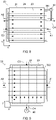
- the temperature sensor 60 is provided in the cathode outlet C4 at which a plurality of second flow paths 24 branched in the cell stack 21 are integrated again into one, but arrangement of the temperature sensor 60 can be changed optionally within a range in which the maximum temperature in the temperature distribution in the fuel cell 20 can be detected or estimated.
- FIG. 8 is an explanatory diagram of a modification in which an attachment position of the temperature sensor 60 is changed. As shown in FIG. 8 , a flow path 301 is provided in which a part of the second flow path 24 branched in the cell stack 21 is drawn out and merges into the cathode outlet C4, and the temperature sensor 60 can be provided in the flow path 301.
- the controller 12 can easily accurately detect or estimate the maximum temperature of the fuel cell 20 regardless of the temperature distribution in the Y direction.
- FIG. 9 is an explanatory diagram of a modification in which a flow path configuration of the fuel and the oxidant gas is changed. That is, instead of the counter-flow cell stack 21, the fuel cell 20 may adopt a cell stack 302 in which the second flow path 24 is a flow path for supplying the oxidant gas to the cell stack 21 such that the oxidant gas flows orthogonally to the fuel.
- the control methods according to the first embodiment and the second embodiment described above can be performed, and effects thereof can be obtained.
- the temperature of the discharged oxidant gas has a constant correlation with the maximum temperature in the temperature distribution in the fuel cell 20, and thus the controller 12 can estimate the maximum temperature of the fuel cell 20 based on the temperature of the discharged oxidant gas.
- a parallel-flow cell stack may also be adopted in which the first flow path 23 and the second flow path 24 are made parallel to each other, and the fuel and the oxidant gas are made to flow through these flow paths in parallel to each other. Also in this case, the control methods according to the first embodiment and the second embodiment described above can be performed, and the effects thereof can be obtained.
- FIG. 10 is an explanatory diagram of a modification in which the flow path configuration of the fuel and the oxidant gas and the attachment position of the temperature sensor 60 are changed with respect to the first embodiment and the second embodiment described above.
- the cross-flow cell stack 302 is adopted, and a flow path 303 is provided in which a part of the second flow path 24 is drawn out and merges into the cathode outlet C4.
- the temperature sensor 60 is provided in the flow path 303.
Landscapes
- Engineering & Computer Science (AREA)
- Chemical & Material Sciences (AREA)
- Life Sciences & Earth Sciences (AREA)
- Manufacturing & Machinery (AREA)
- Sustainable Development (AREA)
- Sustainable Energy (AREA)
- Chemical Kinetics & Catalysis (AREA)
- Electrochemistry (AREA)
- General Chemical & Material Sciences (AREA)
- Combustion & Propulsion (AREA)
- Fuel Cell (AREA)
Applications Claiming Priority (1)
| Application Number | Priority Date | Filing Date | Title |
|---|---|---|---|
| PCT/IB2020/000505 WO2021234426A1 (ja) | 2020-05-22 | 2020-05-22 | 燃料電池システム及び燃料電池システムの制御方法 |
Publications (2)
| Publication Number | Publication Date |
|---|---|
| EP4156350A1 true EP4156350A1 (en) | 2023-03-29 |
| EP4156350A4 EP4156350A4 (en) | 2024-08-07 |
Family
ID=78708148
Family Applications (1)
| Application Number | Title | Priority Date | Filing Date |
|---|---|---|---|
| EP20936088.2A Pending EP4156350A4 (en) | 2020-05-22 | 2020-05-22 | FUEL CELL SYSTEM AND METHOD FOR CONTROLLING THE FUEL CELL SYSTEM |
Country Status (5)
| Country | Link |
|---|---|
| US (1) | US20230197983A1 (ja) |
| EP (1) | EP4156350A4 (ja) |
| JP (1) | JP7323065B2 (ja) |
| CN (1) | CN115702516A (ja) |
| WO (1) | WO2021234426A1 (ja) |
Families Citing this family (1)
| Publication number | Priority date | Publication date | Assignee | Title |
|---|---|---|---|---|
| US20230238552A1 (en) * | 2022-01-21 | 2023-07-27 | General Electric Company | Solid oxide fuel cell assembly |
Family Cites Families (6)
| Publication number | Priority date | Publication date | Assignee | Title |
|---|---|---|---|---|
| US6299994B1 (en) * | 1999-06-18 | 2001-10-09 | Uop Llc | Process for providing a pure hydrogen stream for use with fuel cells |
| JP2012119244A (ja) * | 2010-12-03 | 2012-06-21 | Panasonic Corp | 燃料電池システム |
| JP2016024950A (ja) * | 2014-07-18 | 2016-02-08 | 日本特殊陶業株式会社 | 燃料電池システムの制御装置及び燃料電池システムの制御方法 |
| JP6734048B2 (ja) | 2015-12-22 | 2020-08-05 | 三菱日立パワーシステムズ株式会社 | 燃料電池カートリッジ及び燃料電池モジュール並びに燃料電池カートリッジの制御装置及び制御方法 |
| US20190393525A1 (en) * | 2017-01-31 | 2019-12-26 | SOLIDpower SA | Method and system for producing hydrogen, electricity and co-production |
| JP6755288B2 (ja) * | 2018-10-30 | 2020-09-16 | 東京瓦斯株式会社 | 燃料電池システム及びオフガスの再生方法 |
-
2020
- 2020-05-22 EP EP20936088.2A patent/EP4156350A4/en active Pending
- 2020-05-22 US US17/925,422 patent/US20230197983A1/en active Pending
- 2020-05-22 CN CN202080101228.3A patent/CN115702516A/zh active Pending
- 2020-05-22 WO PCT/IB2020/000505 patent/WO2021234426A1/ja unknown
- 2020-05-22 JP JP2022523735A patent/JP7323065B2/ja active Active
Also Published As
| Publication number | Publication date |
|---|---|
| CN115702516A (zh) | 2023-02-14 |
| JPWO2021234426A1 (ja) | 2021-11-25 |
| EP4156350A4 (en) | 2024-08-07 |
| US20230197983A1 (en) | 2023-06-22 |
| JP7323065B2 (ja) | 2023-08-08 |
| WO2021234426A1 (ja) | 2021-11-25 |
Similar Documents
| Publication | Publication Date | Title |
|---|---|---|
| JP2003300704A (ja) | 燃料改質システムおよび燃料電池システム | |
| US9653742B2 (en) | Fuel cell system | |
| EP3691009B1 (en) | Fuel cell system and fuel cell system control method | |
| EP0973219A2 (en) | Control apparatus for reformer and method of controlling reformer using control apparatus | |
| EP4156350A1 (en) | Fuel cell system and method for controlling fuel cell system | |
| US9640819B2 (en) | Fuel cell system | |
| US8808935B2 (en) | Fuel cell system | |
| JP6901231B2 (ja) | 燃料電池の制御装置及び燃料電池の制御方法 | |
| US11380929B2 (en) | Fuel cell system and control method thereof | |
| EP3664204B1 (en) | Fuel cell system and method for controlling fuel cell system | |
| CN110959214B (zh) | 燃料电池系统及其控制方法 | |
| JP2013157134A (ja) | 固体酸化物型燃料電池システム | |
| US9362575B2 (en) | Fuel cell module | |
| US11757121B2 (en) | Fuel cell system and method for controlling fuel cell system | |
| JP2003229157A (ja) | 改質型燃料電池システムの制御装置 | |
| EP3951966B1 (en) | Fuel cell system and method for controlling fuel cell system | |
| JP5378252B2 (ja) | 燃料電池システム、及び、その発電電力目標値の設定方法 | |
| EP3588649B1 (en) | Fuel cell system and control method thereof | |
| JP4824915B2 (ja) | 燃料電池システム | |
| JP2001126748A (ja) | 燃料電池発電装置の運転方法 | |
| JP2023154588A (ja) | 燃料電池システム | |
| JP2021089810A (ja) | 燃料電池システムの制御方法、及び、燃料電池システム | |
| JP2004200108A (ja) | 改質型燃料電池システム | |
| KR20120133273A (ko) | 연료전지 시스템 |
Legal Events
| Date | Code | Title | Description |
|---|---|---|---|
| STAA | Information on the status of an ep patent application or granted ep patent |
Free format text: STATUS: UNKNOWN Free format text: STATUS: THE INTERNATIONAL PUBLICATION HAS BEEN MADE |
|
| PUAI | Public reference made under article 153(3) epc to a published international application that has entered the european phase |
Free format text: ORIGINAL CODE: 0009012 |
|
| STAA | Information on the status of an ep patent application or granted ep patent |
Free format text: STATUS: REQUEST FOR EXAMINATION WAS MADE |
|
| 17P | Request for examination filed |
Effective date: 20221220 |
|
| AK | Designated contracting states |
Kind code of ref document: A1 Designated state(s): AL AT BE BG CH CY CZ DE DK EE ES FI FR GB GR HR HU IE IS IT LI LT LU LV MC MK MT NL NO PL PT RO RS SE SI SK SM TR |
|
| DAV | Request for validation of the european patent (deleted) | ||
| DAX | Request for extension of the european patent (deleted) | ||
| A4 | Supplementary search report drawn up and despatched |
Effective date: 20240710 |
|
| RIC1 | Information provided on ipc code assigned before grant |
Ipc: H01M 8/04701 20160101AFI20240704BHEP |