EP4156137A2 - Kompakte kanaldetektoren für hlk-systeme - Google Patents
Kompakte kanaldetektoren für hlk-systeme Download PDFInfo
- Publication number
- EP4156137A2 EP4156137A2 EP22197600.4A EP22197600A EP4156137A2 EP 4156137 A2 EP4156137 A2 EP 4156137A2 EP 22197600 A EP22197600 A EP 22197600A EP 4156137 A2 EP4156137 A2 EP 4156137A2
- Authority
- EP
- European Patent Office
- Prior art keywords
- detector
- control circuitry
- detection chamber
- signal
- duct
- Prior art date
- Legal status (The legal status is an assumption and is not a legal conclusion. Google has not performed a legal analysis and makes no representation as to the accuracy of the status listed.)
- Withdrawn
Links
Images






Classifications
-
- G—PHYSICS
- G08—SIGNALLING
- G08B—SIGNALLING SYSTEMS, e.g. PERSONAL CALLING SYSTEMS; ORDER TELEGRAPHS; ALARM SYSTEMS
- G08B17/00—Fire alarms; Alarms responsive to explosion
- G08B17/10—Actuation by presence of smoke or gases, e.g. automatic alarm devices for analysing flowing fluid materials by the use of optical means
-
- F—MECHANICAL ENGINEERING; LIGHTING; HEATING; WEAPONS; BLASTING
- F24—HEATING; RANGES; VENTILATING
- F24F—AIR-CONDITIONING; AIR-HUMIDIFICATION; VENTILATION; USE OF AIR CURRENTS FOR SCREENING
- F24F11/00—Control or safety arrangements
- F24F11/30—Control or safety arrangements for purposes related to the operation of the system, e.g. for safety or monitoring
- F24F11/32—Responding to malfunctions or emergencies
- F24F11/33—Responding to malfunctions or emergencies to fire, excessive heat or smoke
-
- F—MECHANICAL ENGINEERING; LIGHTING; HEATING; WEAPONS; BLASTING
- F24—HEATING; RANGES; VENTILATING
- F24F—AIR-CONDITIONING; AIR-HUMIDIFICATION; VENTILATION; USE OF AIR CURRENTS FOR SCREENING
- F24F11/00—Control or safety arrangements
- F24F11/50—Control or safety arrangements characterised by user interfaces or communication
- F24F11/52—Indication arrangements, e.g. displays
- F24F11/526—Indication arrangements, e.g. displays giving audible indications
-
- F—MECHANICAL ENGINEERING; LIGHTING; HEATING; WEAPONS; BLASTING
- F24—HEATING; RANGES; VENTILATING
- F24F—AIR-CONDITIONING; AIR-HUMIDIFICATION; VENTILATION; USE OF AIR CURRENTS FOR SCREENING
- F24F11/00—Control or safety arrangements
- F24F11/88—Electrical aspects, e.g. circuits
-
- F—MECHANICAL ENGINEERING; LIGHTING; HEATING; WEAPONS; BLASTING
- F24—HEATING; RANGES; VENTILATING
- F24F—AIR-CONDITIONING; AIR-HUMIDIFICATION; VENTILATION; USE OF AIR CURRENTS FOR SCREENING
- F24F11/00—Control or safety arrangements
- F24F11/89—Arrangement or mounting of control or safety devices
-
- G—PHYSICS
- G01—MEASURING; TESTING
- G01D—MEASURING NOT SPECIALLY ADAPTED FOR A SPECIFIC VARIABLE; ARRANGEMENTS FOR MEASURING TWO OR MORE VARIABLES NOT COVERED IN A SINGLE OTHER SUBCLASS; TARIFF METERING APPARATUS; MEASURING OR TESTING NOT OTHERWISE PROVIDED FOR
- G01D11/00—Component parts of measuring arrangements not specially adapted for a specific variable
- G01D11/24—Housings ; Casings for instruments
- G01D11/245—Housings for sensors
-
- G—PHYSICS
- G08—SIGNALLING
- G08B—SIGNALLING SYSTEMS, e.g. PERSONAL CALLING SYSTEMS; ORDER TELEGRAPHS; ALARM SYSTEMS
- G08B17/00—Fire alarms; Alarms responsive to explosion
- G08B17/10—Actuation by presence of smoke or gases, e.g. automatic alarm devices for analysing flowing fluid materials by the use of optical means
- G08B17/11—Actuation by presence of smoke or gases, e.g. automatic alarm devices for analysing flowing fluid materials by the use of optical means using an ionisation chamber for detecting smoke or gas
- G08B17/113—Constructional details
-
- F—MECHANICAL ENGINEERING; LIGHTING; HEATING; WEAPONS; BLASTING
- F24—HEATING; RANGES; VENTILATING
- F24F—AIR-CONDITIONING; AIR-HUMIDIFICATION; VENTILATION; USE OF AIR CURRENTS FOR SCREENING
- F24F2110/00—Control inputs relating to air properties
- F24F2110/50—Air quality properties
- F24F2110/64—Airborne particle content
-
- F—MECHANICAL ENGINEERING; LIGHTING; HEATING; WEAPONS; BLASTING
- F24—HEATING; RANGES; VENTILATING
- F24F—AIR-CONDITIONING; AIR-HUMIDIFICATION; VENTILATION; USE OF AIR CURRENTS FOR SCREENING
- F24F2110/00—Control inputs relating to air properties
- F24F2110/50—Air quality properties
- F24F2110/65—Concentration of specific substances or contaminants
- F24F2110/70—Carbon dioxide
-
- F—MECHANICAL ENGINEERING; LIGHTING; HEATING; WEAPONS; BLASTING
- F24—HEATING; RANGES; VENTILATING
- F24F—AIR-CONDITIONING; AIR-HUMIDIFICATION; VENTILATION; USE OF AIR CURRENTS FOR SCREENING
- F24F2110/00—Control inputs relating to air properties
- F24F2110/50—Air quality properties
- F24F2110/65—Concentration of specific substances or contaminants
- F24F2110/72—Carbon monoxide
-
- F—MECHANICAL ENGINEERING; LIGHTING; HEATING; WEAPONS; BLASTING
- F24—HEATING; RANGES; VENTILATING
- F24F—AIR-CONDITIONING; AIR-HUMIDIFICATION; VENTILATION; USE OF AIR CURRENTS FOR SCREENING
- F24F2110/00—Control inputs relating to air properties
- F24F2110/50—Air quality properties
- F24F2110/65—Concentration of specific substances or contaminants
- F24F2110/76—Oxygen
Definitions
- a detector in an embodiment, includes a detection chamber configured to receive an air sample; a sensor configured to detect a particle level in the air sample and generate a detection signal based on the particle level; a control circuitry configured to receive the detection signal and generate a communication signal or a control signal based on the received detection signal, wherein the control circuitry is disposed vertically above the detection chamber; and a sealing gasket that seals the control circuitry from the detection chamber.
- a system in another embodiment, includes a first detector configured to operate as a parent detector and a second detector, in communication with the first detector and configured to operate as a child detector, the first detector including: a detection chamber including a first sensor configured to detect a first particle level in a first air sample; a control circuitry disposed vertically above the detection chamber and configured to generate first signal based on the detected particle level; a sealing gasket that seals the control circuitry from the detection chamber; the second detector including: a second sensor configured to detect a second particle level of the in a second air sample; and the control circuitry in the first detector further configured to: generate a second signal based on the second particle level detected by the second sensor.
- duct detectors As smaller space is being assigned to HVACs and the associated ductwork in commercial buildings, there has been a desire for duct detectors with a smaller footprint.
- Currently available detectors tend to be bulky and cumbersome.
- the housing industry furthermore requires the duct detectors to be conveniently repairable and serviceable, attributes which are lacking in existing design of duct detectors. For instance, in existing duct detectors, a repair personnel may have to break a seal to access a component and then repair the broken seal after the component has been serviced. Repeated service may damage the seal permanently and require the entire duct detector to be replaced. Therefore, there is also a desire for duct detectors with an easier repairability and serviceability.
- An HVAC alarm system may have multiple interconnected duct detectors. For instance, a first duct detector may generate an alarm condition that may be communicated to other duct detectors for the receiving duct detectors to trigger visual and/or audible alarms.
- Some of the interconnected duct detectors may include duct detectors with a reduced functionality, e.g., having a relatively simple control circuitry.
- the duct detectors with such reduced functionality may exchange communication signals with another duct detector, e.g., functioning as a parent duct detector to the child duct detector with the reduced functionality, for the parent duct detector to perform a more complex analysis on the sensing data from the child duct detector.
- the child detector may be even smaller than the parent duct detector and can be deployed at even tighter spaces.
- FIG. 1 shows an example of a detector 100 installed in a ductwork 102.
- the installation of detector 100 to the ductwork 102 may be performed by boring one or more holes in the ductwork 102. These bored holes may be used for a sampling tube 104 and an exhaust tube 106.
- the sampling tube 104 arranged perpendicular to an airflow 110, may span the entire cross-sectional width of the ductwork 102.
- Several holes 108 in the sampling tube 104 may allow a portion of the airflow 110 to be collected into the sampling tube 104.
- the sampling tube 104 may therefore sample air flowing through the ductwork 102 for the entire (or at least a large part of) cross-sectional width of the ductwork 102.
- the top cover 302 may be affixed to the detector 100 (e.g., the bottom assembly 314) using a hinge 404. To access the internal components, repair personnel may swivel the top cover 302 on the hinge 404.
- the top cover 302 may be made up of any kind of material. For instance, the top cover 302 may be made up of a polycarbonate material.
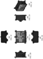
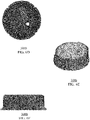
- the bench assembly 306 may be made up of three parts: a top part 502, which may be a PC/ABS (Polycarbonate/Acrylonitrile Butadiene Styrene) blend; a middle part 504, which may be a clear polycarbonate; and a bottom part 506, which may be a PC/ABS blend.
- the upper portion of the bench assembly 306 may be connected to the PCB 304.
- the sensing head of the detector 100 may be integrated with a single PCB 304 design.
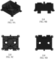
- the chamber cover 308 may define the detection chamber-e.g., the chamber cover 308 may form the bottom and side walls of the detection chamber (the PCB 304 may form the top wall of the detection chamber).
- the chamber cover 308 may therefore provide an isolated environment for the sensors in the detection chamber (e.g., sensors in the bench assembly 306) to detect smoke (e.g., presence and/or level of) and/or any other particles in the sampled air; and/or to measure other attributes of the sampled air.
- the chamber cover 308 may block the sampled air from leaking to other components of the detector 100.
- the chamber cover 308 may be composed of, for example, an ABS material, and/or any other plastic material.
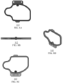
- the seal 312 may be kept intact because the logic and analysis components (e.g., control circuitry) of the PCB 304 can be accessed without breaking the seal 312.
- the seal 312 may be made up of rubber (e.g., Thermoplastic Vulcanizates (TPV) rubber).
- the sensing element 1002 may include any type of sensor, such as a smoke sensor, particle sensor, gas sensor, and/or a combination of different types of sensors.
- the sensing element 1002 may include a smoke sensor that may operate according to the principle of photoelectric smoke detection (e.g., multi wavelength photoelectric smoke detection), or according to the principle of ionization smoke detection, or a combination of both. These principles of operation are mere examples, and any kind of principle of operation within the smoke sensor forming the sensing element 1002 should be considered within the scope of this disclosure.
- the sensing element 1002 may be disposed in a bench assembly (e.g., bench assembly 306 shown in FIGS. 5A-5C ).
- the additional sensing element 1018 may also include a sensor for measuring the level of refrigerant (which may be from a leakage) in the sampled air.
- the measured data may be transmitted by the additional status sensing element 1018 to the processor 1004.
- the sensing element 1002 and the additional status sensing element 1018 may be similar and may measure the same attribute at different points.
- the additional status sensing element 1018 may be a back-up sensor that may take over the functionality of the sensing element 1002 if the sensing element 1002 malfunctions.
- the sensing element 1002 and the additional status sensing element 1018 may be used to calibrate each other.
- the inputs 1006 may include any inputs (e.g., inputs other than the measurement data from the sensing element 1002 and the additional status sensing element 1018) to the detector. As shown, the inputs 1006 may include the interconnect input 1008 and the remote input 1010.
- the interconnect input 1010 may be connected to other detectors and/or to a control panel (e.g., fire alarm control panel, FACP).
- a threshold voltage detected at the interconnect input 1008 may indicate that an alarm condition is triggered at least another detector. For example, a voltage of 18 V detected at the interconnect input 1008 may indicate a global shutdown condition, and a voltage of 24 V detected at the interconnect input 1010 may indicate a global shutdown with a reset condition.
- the remote input 1010 may receive signals from other detectors (e.g., a master detector) or the control panels. The signals may be series of voltage pulses, which may control signals and/or measurement data generated by other detectors.
- the outputs 1012 may include any type of output that may indicate an alarm condition at the detector and/or signals for one or more components to shut down. Examples of the outputs 1012 may include a relay output 1014 and a voltage output 1016.
- the relay output 1014 may indicate an alarm condition at the detector, e.g., a normally closed alarm relay contact may be thrown into a closed position upon detecting the smoke thereby generating the voltage at the relay output 1014.
- the voltage output 1016 may generate voltage as signals to control other components in the system. For instance, in response to an alarm condition, the processor 1004 may cause the voltage output 1016 to generate a signal to shut off the HVAC system and/or actuate dampers within the ductwork.
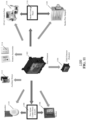
- FIG. 11 shows an example of an HVAC alarm system 1100.
- the HVAC alarm system 1100 may include components such as a duct detector 1102 (e.g., duct detector 100 shown in FIGS. 1-3 ), a child detector 1104 that may be remote from the duct detector 1102, strobes 1106, fire alarm control panel (FACP) 1108, horns/sounders 1110, auxiliary relays 1112, remote accessories 1114, HVAC controls/fans 1116, smoke control panel 1118, and smoke/fire dampers 1120.
- FACP fire alarm control panel
- the FACP 1108 may include any kind of fire control panel that may communicate with multiple detectors 1102, strobes 1106, horns/sounders, and/or any other components in the system 1100 that are associated with generating and/or mitigating fire alarm conditions.
- the FACP may be wall mounted and may be remote from the other components.
- the FACP 1108 may communicate with the other components through wired and/or wireless communication means.
- the interface e.g., buttons, touchscreens
- the interface provided by the FACP 1108 may be used to configure different attributes (e.g., sensitivity, communication preferences) of the components in the system 1100.
- the HVAC control/fans 1116 may include any kind of control mechanism in the HVAC system.
- the HVAC controls may include, for example, a thermostat unit that shuts off the HVAC in response to receiving a signal from the duct detector 1102. In other words, air circulating through the ductwork may be stopped by shutting down the HVAC system in response to detecting smoke or any other alarm condition.
- one or more fans may be turned off to stop the flow of the smoke through the ductwork. In some instances, one or more fans may be turned on to deflect the flow of smoke away from rooms or the places where people may be present.
- the smoke/fire dampers 1120 may be mechanical components that may stem the flow of smoke or fire through the ductwork. For instance, upon detection of smoke, the duct detector may transmit a control signals to an actuator associated with the dampers 1120. The actuator may in turn cause the dampers to close, thereby stopping a downstream flow of the circulating air. In some examples, the smoke control panel 1118 may provide the control signal to the smoke/fire dampers 1120 in response to receiving an alarm condition from the duct detector 1102. Although the damper mechanism is shown and described herein, any kind of mechanism that stems the downstream flow of the circulating air should be considered within the scope of this disclosure.
Landscapes
- Engineering & Computer Science (AREA)
- Chemical & Material Sciences (AREA)
- General Engineering & Computer Science (AREA)
- Combustion & Propulsion (AREA)
- Mechanical Engineering (AREA)
- Physics & Mathematics (AREA)
- General Physics & Mathematics (AREA)
- Emergency Management (AREA)
- Business, Economics & Management (AREA)
- Analytical Chemistry (AREA)
- Human Computer Interaction (AREA)
- Fire-Detection Mechanisms (AREA)
- Duct Arrangements (AREA)
Applications Claiming Priority (1)
| Application Number | Priority Date | Filing Date | Title |
|---|---|---|---|
| US17/448,743 US12130032B2 (en) | 2021-09-24 | 2021-09-24 | Compact duct detectors for HVAC systems |
Publications (2)
| Publication Number | Publication Date |
|---|---|
| EP4156137A2 true EP4156137A2 (de) | 2023-03-29 |
| EP4156137A3 EP4156137A3 (de) | 2023-06-21 |
Family
ID=83447745
Family Applications (1)
| Application Number | Title | Priority Date | Filing Date |
|---|---|---|---|
| EP22197600.4A Withdrawn EP4156137A3 (de) | 2021-09-24 | 2022-09-23 | Kompakte kanaldetektoren für hlk-systeme |
Country Status (2)
| Country | Link |
|---|---|
| US (1) | US12130032B2 (de) |
| EP (1) | EP4156137A3 (de) |
Families Citing this family (3)
| Publication number | Priority date | Publication date | Assignee | Title |
|---|---|---|---|---|
| DE202022106612U1 (de) * | 2022-11-25 | 2023-01-24 | Danfoss A/S | Kapselung und Heizungs-, Lüftungs- und Klimaanlage, die die Kapselung umfasst |
| DE202023103907U1 (de) * | 2023-07-12 | 2023-09-29 | Danfoss A/S | Gehäuse für einen Kältemittelgasleckdetektionssensor und Kältemittelgasleckdetektionssensor mit einem Gehäuse |
| US20250155902A1 (en) * | 2023-11-09 | 2025-05-15 | Danfoss A/S | Gas sensing leak mitigation unit |
Family Cites Families (15)
| Publication number | Priority date | Publication date | Assignee | Title |
|---|---|---|---|---|
| US5844148A (en) * | 1997-07-30 | 1998-12-01 | Pittway Corporation | Detector with adjustable sampling tubes |
| AUPQ553800A0 (en) * | 2000-02-10 | 2000-03-02 | Cole, Martin Terence | Improvements relating to smoke detectors particularily duct monitored smoke detectors |
| US20050057367A1 (en) | 2003-09-12 | 2005-03-17 | Simplexgrinnell Lp | Alarm system device |
| US7331213B2 (en) * | 2004-08-03 | 2008-02-19 | Siemens Schweiz Ag | Sensor device for determining constituents of a flowing medium |
| WO2008109933A1 (en) * | 2007-03-09 | 2008-09-18 | Xtralis Technologies Ltd | Particle detection apparatus |
| US8285127B2 (en) * | 2007-09-05 | 2012-10-09 | Tpi Corporation | In-line duct supplemental heating and cooling device and method |
| KR101529734B1 (ko) | 2008-03-31 | 2015-06-17 | 노미 보사이 가부시키가이샤 | 전기 기기 및 연기 감지기 |
| US8015873B2 (en) * | 2008-04-25 | 2011-09-13 | Hall David L | Detector housing |
| US8443652B2 (en) * | 2009-10-01 | 2013-05-21 | Calectro Aktiebolag | Fluid detector |
| CN104330285B (zh) | 2010-09-10 | 2018-08-07 | 爱克斯崔里斯科技有限公司 | 管道检测器 |
| US20120193086A1 (en) * | 2011-01-28 | 2012-08-02 | Tasseron Sensors, Inc. | Thermal probe |
| KR101125188B1 (ko) * | 2011-09-08 | 2012-03-20 | 주식회사 엔케이 | 화재진압용 스모크 디텍터 장치 |
| US10291292B2 (en) * | 2014-09-02 | 2019-05-14 | Johnson Controls Technology Company | Wireless sensor with near field communication circuit |
| US9792793B2 (en) | 2015-07-13 | 2017-10-17 | Hamilton Sundstrand Corporation | Smoke detector |
| US11796198B2 (en) * | 2018-07-24 | 2023-10-24 | Precision Systems Integration, Llc | System and method for monitoring air quality while cooling an outdoor electronic display assembly |
-
2021
- 2021-09-24 US US17/448,743 patent/US12130032B2/en active Active
-
2022
- 2022-09-23 EP EP22197600.4A patent/EP4156137A3/de not_active Withdrawn
Also Published As
| Publication number | Publication date |
|---|---|
| US12130032B2 (en) | 2024-10-29 |
| US20230109770A1 (en) | 2023-04-13 |
| EP4156137A3 (de) | 2023-06-21 |
Similar Documents
| Publication | Publication Date | Title |
|---|---|---|
| EP4156137A2 (de) | Kompakte kanaldetektoren für hlk-systeme | |
| RU2342709C2 (ru) | Способ и устройство для обнаружения пожара и определения его места | |
| CN102054322B (zh) | 火灾传感器和火灾检测方法 | |
| US9506668B2 (en) | Make-up air system and method | |
| EP2438360B1 (de) | Gasdetektor | |
| CN105960583B (zh) | 对呼吸取样系统的改进 | |
| US7262705B2 (en) | Recessed detector assembly for detecting and venting airborne substances | |
| CA2921709A1 (en) | Hazardous gas response system | |
| KR20220076374A (ko) | 화재 안전 모니터링 시스템 | |
| CN107667262B (zh) | 通风系统 | |
| KR101931912B1 (ko) | 공기의 유동경로를 변화시키는 환기시스템 | |
| KR20120032898A (ko) | 외기냉방기능을 가진 폐열회수 환기시스템의 제어방법 | |
| US7015820B2 (en) | Apparatus for monitoring a smoke detector | |
| KR100988386B1 (ko) | 화재 감지기의 분진 제거장치 | |
| JP6063186B2 (ja) | ヒュームフードの人検知センサ故障判定方法および装置 | |
| KR102031650B1 (ko) | 전열교환기 무선 연동으로 오염표시 기능을 갖는 환기시스템 | |
| EP3996059B1 (de) | Rauchmelderempfindlichkeit für die gesundheitsüberwachung von gebäuden | |
| US12592137B2 (en) | Condensation monitoring in aspirating smoke detection systems | |
| KR20210122966A (ko) | 통합 실내 환경 관리 시스템 및 방법 | |
| CN107067634A (zh) | 一种无迷宫感烟探测光室结构 | |
| KR102828185B1 (ko) | 방화댐퍼 제어장치 | |
| JPH08147580A (ja) | 建物防災システム | |
| KR200343946Y1 (ko) | 화재 경보용 공기 청정기 | |
| KR200310395Y1 (ko) | 다중 경보가 가능한 실내환경 감시 검측기 | |
| Petrov | Determining the best location of smoke sensor in office room |
Legal Events
| Date | Code | Title | Description |
|---|---|---|---|
| PUAI | Public reference made under article 153(3) epc to a published international application that has entered the european phase |
Free format text: ORIGINAL CODE: 0009012 |
|
| STAA | Information on the status of an ep patent application or granted ep patent |
Free format text: STATUS: THE APPLICATION HAS BEEN PUBLISHED |
|
| AK | Designated contracting states |
Kind code of ref document: A2 Designated state(s): AL AT BE BG CH CY CZ DE DK EE ES FI FR GB GR HR HU IE IS IT LI LT LU LV MC MK MT NL NO PL PT RO RS SE SI SK SM TR |
|
| PUAL | Search report despatched |
Free format text: ORIGINAL CODE: 0009013 |
|
| AK | Designated contracting states |
Kind code of ref document: A3 Designated state(s): AL AT BE BG CH CY CZ DE DK EE ES FI FR GB GR HR HU IE IS IT LI LT LU LV MC MK MT NL NO PL PT RO RS SE SI SK SM TR |
|
| RIC1 | Information provided on ipc code assigned before grant |
Ipc: G08B 17/113 20060101AFI20230512BHEP |
|
| STAA | Information on the status of an ep patent application or granted ep patent |
Free format text: STATUS: THE APPLICATION IS DEEMED TO BE WITHDRAWN |
|
| 18D | Application deemed to be withdrawn |
Effective date: 20231222 |