EP4155501B1 - Hydraulisches system mit sicherheitsmodus, gesteinsbohrgestell und verfahren - Google Patents
Hydraulisches system mit sicherheitsmodus, gesteinsbohrgestell und verfahren Download PDFInfo
- Publication number
- EP4155501B1 EP4155501B1 EP21198713.6A EP21198713A EP4155501B1 EP 4155501 B1 EP4155501 B1 EP 4155501B1 EP 21198713 A EP21198713 A EP 21198713A EP 4155501 B1 EP4155501 B1 EP 4155501B1
- Authority
- EP
- European Patent Office
- Prior art keywords
- hydraulic
- rock drilling
- drilling
- actuator
- hydraulic system
- Prior art date
- Legal status (The legal status is an assumption and is not a legal conclusion. Google has not performed a legal analysis and makes no representation as to the accuracy of the status listed.)
- Active
Links
Images

Classifications
-
- E—FIXED CONSTRUCTIONS
- E21—EARTH OR ROCK DRILLING; MINING
- E21B—EARTH OR ROCK DRILLING; OBTAINING OIL, GAS, WATER, SOLUBLE OR MELTABLE MATERIALS OR A SLURRY OF MINERALS FROM WELLS
- E21B7/00—Special methods or apparatus for drilling
- E21B7/02—Drilling rigs characterised by means for land transport with their own drive, e.g. skid mounting or wheel mounting
- E21B7/022—Control of the drilling operation; Hydraulic or pneumatic means for activation or operation
-
- E—FIXED CONSTRUCTIONS
- E21—EARTH OR ROCK DRILLING; MINING
- E21B—EARTH OR ROCK DRILLING; OBTAINING OIL, GAS, WATER, SOLUBLE OR MELTABLE MATERIALS OR A SLURRY OF MINERALS FROM WELLS
- E21B44/00—Automatic control systems specially adapted for drilling operations, i.e. self-operating systems which function to carry out or modify a drilling operation without intervention of a human operator, e.g. computer-controlled drilling systems; Systems specially adapted for monitoring a plurality of drilling variables or conditions
- E21B44/02—Automatic control of the tool feed
-
- E—FIXED CONSTRUCTIONS
- E21—EARTH OR ROCK DRILLING; MINING
- E21B—EARTH OR ROCK DRILLING; OBTAINING OIL, GAS, WATER, SOLUBLE OR MELTABLE MATERIALS OR A SLURRY OF MINERALS FROM WELLS
- E21B7/00—Special methods or apparatus for drilling
- E21B7/02—Drilling rigs characterised by means for land transport with their own drive, e.g. skid mounting or wheel mounting
- E21B7/025—Rock drills, i.e. jumbo drills
Definitions
- the invention relates to a hydraulic system of a rock drilling rig.
- the hydraulic system is provided with a safety mode for improving safety.
- the invention further relates to a rock drilling rig and to a method for ensuring safe operation of a hydraulic drilling actuator.
- rock drilling rigs In mines and at other work sites different type of rock drilling rigs are used for drilling blast holes, reinforcing holes and other type of holes by means of rock drilling machines mounted on booms of the rock drilling rigs.
- the rock drilling machine may be hydraulically operable and may be surrounded by a safety cage or noise dampener, or there may other safety devices preventing entering inside a security zone of rotating machine elements.
- a hydraulic system powering hydraulic actuators of the hydraulic rock drilling machine need to be provided with a safety function feature for limiting their output performance into a safe level.
- An object of the invention is to provide a novel and improved hydraulic system, and a rock drilling rig equipped with such hydraulic system, and further to a novel and improved method for improving operational safety by limiting output performance temporarily.
- the hydraulic system according to the invention is characterized by the characterizing features of the first independent apparatus claim.
- the rock drilling rig according to the invention is characterized by the characterizing features of the second independent apparatus claim.
- the method according to the invention is characterized by the characterizing features of the independent method claim.
- a hydraulic system of a rock drilling rig comprises at least one hydraulic circuit provided with a hydraulic power unit comprising a hydraulic pump driven by means of a motor. At least one hydraulic drilling actuator is powered by hydraulic pressure and flow generated by the mentioned hydraulic power unit. Further, the hydraulic system is provided with a safety function feature for limiting features of the input hydraulic fluid directed to the mentioned at least one hydraulic drilling actuator for temporarily limiting output performance of the hydraulic drilling actuator. And wherein the hydraulic system is provided with at least one control unit comprising at least one restricted operating mode (ROM) serving as the mentioned safety function feature and configured to limit magnitude of output flow of the pumping unit whereby motion speed of the drilling actuator is limited due to received limited magnitude of input flow.
- ROM restricted operating mode
- the hydraulic pump is a fixed displacement hydraulic pump driven by means of an electric motor.
- the electric motor is controlled by means of at least one electrical motor control device, and the control unit is configured to control the electrical motor control device for controlling rotation speed of the electric motor and the hydraulic pump. Further, the limited output flow of the hydraulic fluid is implemented under control of the control unit in response to the selected restricted operating mode (ROM).
- ROM restricted operating mode
- the output performance of the drilling actuator is limited already at the pumping unit whereby no restricting valves or other control elements are needed in connection with hydraulic channels or at the drilling actuator.
- An advantage of the disclosed solution is that since no external valves or valve assemblies are needed in the system, pressure and power losses can be avoided. This applies in the restricted operating mode and in a normal drilling mode. Furthermore, the hydraulic circuits can be simple and may contain fewer components.
- a further advantage is that the present solution provides accurate speed control for the controlled hydraulic drilling actuator during the ROM -mode, which is beneficial not only for security issues but also for operational measures.
- the motor for driving a fixed displacement hydraulic pump is a speed controlled electric motor controlled by means of variable frequency drive serving as an electrical motor control device for controlling rotation speed of the electric motor.
- the mentioned variable frequency drive comprises an integrated safety function based on hard wired safety circuit.
- control unit is provided with at least one input limit value for the restricted operating mode (ROM).
- the input limit value is configured to define maximum rotation speed of a rotating device of the rock drilling machine and a drilling tool connectable to the rock drilling machine.
- the input limit value defines maximum magnitude of output flow of the hydraulic fluid produced by the hydraulic pump and directed to at least one hydraulic actuator of the rock drilling machine.
- the maximum flow is defined so that the maximum rotation speed cannot be exceeded.
- control unit is provided with at least one input limit value for the restricted operating mode (ROM).
- the input limit value is configured to define maximum feed speed of a feed device of the rock drilling machine and a drilling tool connectable to the rock drilling machine.
- the feed device may be a hydraulic motor or a hydraulic cylinder.
- the input limit value defines maximum magnitude of output flow of the hydraulic fluid produced by the hydraulic pump and directed to at least one hydraulic actuator of the rock drilling machine.
- the maximum flow is defined so that the maximum feed speed cannot be exceeded.
- control unit is configured to execute the restricted operating mode (ROM) in response to a received safety signal indicating opening or activation of a safety device surrounding the rock drilling machine or being in connection with the rock drilling rig.
- ROM restricted operating mode
- the safety device is a safety door, a safety cage, or a door of a noise dampener, for example.
- the safety device may be provided with one or more sensors for monitoring status of the safety device.
- the safety device may comprise a safety line and a safety switch connected to the safety line.
- the disclosed solution relates to a rock drilling rig comprising: a movable carrier; at least one boom connected to the carrier; at least one rock drilling unit mounted to a distal end portion of the boom, wherein the rock drilling unit comprises a feed beam and a rock drilling machine mounted movably on the feed beam.
- the rock drilling rig further comprises a hydraulic system, whereby the rock drilling machine comprises at least one hydraulic actuator powered by the hydraulic system.
- the hydraulic system is in accordance with the features and embodiments disclosed in this document, whereby the hydraulic actuator of the rock drilling machine is controllable under a restricted operating mode with a limited performance.
- the disclosed solution relates to method for limiting output performance of a hydraulic drilling actuator temporarily under execution of a safety function feature in a hydraulic system.
- the method comprises limiting hydraulic features of the input hydraulic fluid directed to the hydraulic drilling actuator connected to a hydraulic circuit of the hydraulic system.
- the output performance of the drilling actuator is limited by limiting produced hydraulic fluid flow in the hydraulic circuit of the hydraulic drilling actuator, whereby restricted magnitude of the fluid flow is produced at a hydraulic pump of the hydraulic circuit for the duration of a restricted operation mode of the safety feature.
- the disclosed restricted operation mode i.e., ROM -mode may be based on requirements of a standard EN16228 and may comprise the following measures:
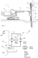
- Figure 1 shows a rock drilling rig 1 comprising a movable carrier 2 and one or more booms 3 connected to the carrier 2.
- the boom 3 may be provided with a rock drilling unit 4 comprising a feed beam 5 on which is arranged movably a rock drilling machine 6.
- the rock drilling machine 6 may comprise an impact device 7 for providing a rock drilling tool 8 with impact pulses for breaking rock material being drilled, and a rotating device 9 for rotating the drilling tool 8 around its longitudinal axis.
- the rock drilling machine 6 is moved in drilling direction A and in reverse direction B by means of a feed device 10.
- the rock drilling unit 4 may further comprise one or more safety devices Sd such as protective cages, covers, noise dampers or safety lines, for preventing an operator entering close to rotating and moving machine elements.
- Figure 1 further discloses that the rock drilling rig 1 comprises a power unit Pu for producing needed pressurized hydraulic fluid flow to hydraulically operable drilling actuators of the rock drilling unit 4.
- the rotating device 9 and the feed device 10 may be hydraulically operable drilling actuators driven by the power unit Pu, as well as the impact device 7.
- Figure 1 discloses a surface rock drilling rig 1 for drilling blast holes, but the solution disclosed in this document can be utilized also in underground drilling and in reinforcing devices, such as in rock bolting solutions.
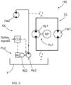
- FIG 2 discloses a hydraulic system HS of a rock drilling rig.
- the hydraulic system HS comprises a closed loop hydraulic circuit CL with a first hydraulic power unit Pu1, and an open loop hydraulic circuit OL with a second hydraulic power unit Pu2.
- the closed loop hydraulic circuit CL comprises a first hydraulic pump Hp1 driven by means of a first motor M1.
- a first hydraulic drilling actuator Ha1 is connected to the closed loop hydraulic circuit CL.
- the first hydraulic drilling actuator Ha1 may be a rotating device.
- pressurized hydraulic fluid is directed to circulate in the closed loop hydraulic circuit CL from an outlet port of the first hydraulic pump Hp1 to an inlet port of the first hydraulic drilling actuator Ha1 and further from an outlet port of the first hydraulic actuator Ha1 to an inlet port of the first hydraulic pump Hp1.
- the first hydraulic pump Hp1 and the first hydraulic drilling actuator Ha1 can be rotated to both rotational directions wherefore the inlet and outlet ports are not marked for clarity reasons.
- the first motor M1 can be controlled by means of an electrical motor controller Mc and control signals can be transmitted to the electrical motor controller Mc from a control unit CU.
- the control unit CU can control for example rotation speed of the first motor M1 accurately and steplessly, and when the first hydraulic pump Hp1 is a fixed displacement pump, then output hydraulic power of the first hydraulic power unit Pu1 can be accurately controlled.
- the control unit CU may comprise a ROM -mode for interrupting a normal mode and allowing safe and slow motion for the first hydraulic actuator Ha1 for a limited duration.
- the ROM -mode may comprise a safety control program or algorithm, parameters, and limit values, which can be input to the control unit CU.
- the control unit CU may also receive safety signals from sensors and safety switches for detecting status of different safety devices, for example.
- the control unit may comprise a processor for executing the input control programs and for generating the needed control signals.
- the open loop hydraulic circuit OL of the hydraulic system of Figure 2 comprises a second hydraulic pump Hp2 driven by means of second motor M2.
- the second hydraulic power unit Pu2 is configured to provide hydraulic power to a second hydraulic drilling actuator Ha2, which may be hydraulic feed device.
- the feed device may be a hydraulic motor or a cylinder.
- the open loop hydraulic circuit OL may be a so called common rail circuit which may provide hydraulic power also for auxiliary actuators of a rock drilling rig. Hydraulic fluid can be selectively fed from the common rail circuit to the closed loop circuit CL if a supplementary amount of hydraulic fluid is needed therein. This is shown in broken lines in Figure 2 . Contrary to the closed loop hydraulic circuit CL, the open loop hydraulic circuit OL circulates the hydraulic fluid via a tank T or reservoir.
- Figure 3 discloses an alternative hydraulic system HS for providing hydraulic power for two hydraulic drilling actuators Ha1 and Ha2.
- the hydraulic circuits CL and OL are quite like the ones shown in previous Figure 2 .
- the second hydraulic power unit Pu2 of the open loop hydraulic circuit OL is provided with the safety feature control.
- the second motor M2 can be controlled under control of the control unit CU and electrical motor control unit Mc, or alternatively, the second hydraulic pump Hp2 may be a variable displacement pump which can be controlled by means of the control unit CU for adjusting the generated fluid flow.
- FIG 4 is a summarizing diagram showing some basic features and alternatives of the disclosed solution. These issues are already disclosed above in this document.
Landscapes
- Life Sciences & Earth Sciences (AREA)
- Engineering & Computer Science (AREA)
- Geology (AREA)
- Mining & Mineral Resources (AREA)
- Physics & Mathematics (AREA)
- Environmental & Geological Engineering (AREA)
- Fluid Mechanics (AREA)
- General Life Sciences & Earth Sciences (AREA)
- Geochemistry & Mineralogy (AREA)
- Earth Drilling (AREA)
- Fluid-Pressure Circuits (AREA)
Claims (5)
- Hydrauliksystem (HS) einer Gesteinsbohranlage (1), umfassend:mindestens einen Hydraulikkreis (CL, OL), der mit einer hydraulischen Leistungseinheit (Pu) versehen ist, umfassend eine Hydraulikpumpe (Hp), die mittels eines Motors (M) angetrieben wird;mindestens einen hydraulischen Bohraktuator (Ha), der durch hydraulischen Druck und Fluss, die durch die erwähnte hydraulische Leistungseinheit (Pu) erzeugt werden, mit Leistung versorgt wird;wobei das Hydrauliksystem (HS) mit einer Sicherheitsmaßnahmefunktion zum Begrenzen der Funktionen des Eingangshydraulikfluids versehen ist, das zu dem erwähnten mindestens einen hydraulischen Bohraktuator (Ha) zum vorübergehenden Begrenzen der Ausgangsleistung des hydraulischen Bohraktuators (Ha) geleitet wird; unddas Hydrauliksystem (HS) mit mindestens einer Steuereinheit (CU) bereitgestellt ist, umfassend mindestens einen eingeschränkten Betriebsmodus (ROM), der als die erwähnte Sicherheitsmaßnahmefunktion dient und konfiguriert ist, um die Größe des Ausgangsflusses des Pumpaggregats (Pu) zu begrenzen, wodurch die Bewegungsgeschwindigkeit des hydraulischen Bohraktuators (Ha) aufgrund der empfangenen begrenzten Größe des Eingangsflusses begrenzt wird,dadurch gekennzeichnet, dassdie Hydraulikpumpe (Hp) eine Konstanthydraulikpumpe ist, die mittels eines Elektromotors (M) angetrieben wird;der Elektromotor (M) mittels mindestens einer elektrischen Motorsteuervorrichtung (Mc) gesteuert wird; unddie Steuereinheit (CU) konfiguriert ist, um die elektrische Motorsteuervorrichtung (Me) zum Steuern der Drehzahl des Elektromotors (M) und der Hydraulikpumpe (Hp) zu steuern;wobei der Motor (M) ein drehzahlgeregelter Elektromotor ist, der mittels eines Frequenzumrichters gesteuert wird, der als die elektrische Motorsteuervorrichtung (Mc) dient,wobei der erwähnte Frequenzumrichter eine integrierte Sicherheitsmaßnahme basierend auf einer festverdrahteten Sicherheitsschaltung umfasst; undder begrenzte Ausgangsfluss des Hydraulikfluids unter Steuerung der Steuereinheit (CU) als Reaktion auf den ausgewählten eingeschränkten Betriebsmodus (ROM) implementiert wird.
- Hydrauliksystem nach Anspruch 1, dadurch gekennzeichnet, dassdie Steuereinheit (CU) mit mindestens einem Eingangsgrenzwert für den eingeschränkten Betriebsmodus (ROM) versehen ist; undder Eingangsgrenzwert konfiguriert ist, um die maximale Drehzahl einer Drehvorrichtung (9) der Gesteinsbohrmaschine (6) und eines Bohrwerkzeugs (8), das mit der Gesteinsbohrmaschine (6) verbindbar ist, zu definieren.
- Hydrauliksystem nach Anspruch 1 oder 2,
dadurch gekennzeichnet, dassdie Steuereinheit (CU) mit mindestens einem Eingangsgrenzwert für den eingeschränkten Betriebsmodus (ROM) versehen ist; undder Eingangsgrenzwert konfiguriert ist, um die maximale Vorschubgeschwindigkeit einer Zuführvorrichtung (10), die die Gesteinsbohrmaschine (6) speist, und ein Bohrwerkzeug (8), das mit der Gesteinsbohrmaschine (6) verbindbar ist, zu definieren. - Gesteinsbohranlage (1), umfassend:einen beweglichen Träger (2);mindestens einen Ausleger (3), der mit dem Träger (2) verbunden ist;mindestens eine Gesteinsbohreinheit (4), die an einem distalen Endabschnitt des Auslegers (3) montiert ist, wobei die Gesteinsbohreinheit (4) einen Zuführträger (5) und eine Gesteinsbohrmaschine (6) umfasst, die auf dem Zuführträger (5) beweglich montiert ist;ein Hydrauliksystem (HS);und wobei die Gesteinsbohrmaschine (6) mindestens einen hydraulischen Aktuator (Ha) umfasst, der durch das Hydrauliksystem (HS) mit Leistung versorgt wird;dadurch gekennzeichnet, dassdas Hydrauliksystem (HS) gemäß einem der vorstehenden Ansprüche 1 bis 3 ist, wodurch der hydraulische Bohraktuator (Ha) der Gesteinsbohreinheit (4) unter einem eingeschränkten Betriebsmodus (ROM) mit einer begrenzten Leistung steuerbar ist.
- Verfahren zum vorübergehenden Begrenzen der Ausgangsleistung eines hydraulischen Bohraktuators (Ha) unter Ausführung einer Sicherheitsmaßnahmefunktion eines Hydrauliksystems (HS);wobei das Verfahren das Begrenzen von hydraulischen Funktionen des Eingangshydraulikfluids umfasst, das zu dem hydraulischen Bohraktuator (Ha) geleitet wird, der mit einem Hydraulikkreis (CL, OL) des Hydrauliksystems (HS) verbunden ist; undBegrenzen der Ausgangsleistung des hydraulischen Bohraktuators (Ha) durch Begrenzen des produzierten Hydraulikfluidflusses in dem Hydraulikkreis (CL, OL) des hydraulischen Bohraktuators (Ha), wodurch eine begrenzte Größe des Fluidflusses an einer Hydraulikpumpe (Hp) des Hydraulikkreises für die Dauer eines eingeschränkten Betriebsmodus der Sicherheitsmaßnahme produziert wird,gekennzeichnet durchAntreiben der Hydraulikpumpe (Hp) mittels eines Elektromotors (M); undSteuern der Drehzahl des Elektromotors (M) und der Hydraulikpumpe (Hp), um die eingeschränkte Größe des Hydraulikfluids zu produzieren;wobeider Motor (M) ein drehzahlgeregelter Elektromotor ist, der mittels eines Frequenzumrichters gesteuert wird, der als die elektrische Motorsteuervorrichtung (Mc) dient; undder erwähnte Frequenzumrichter eine integrierte Sicherheitsmaßnahme basierend auf einer festverdrahteten Sicherheitsschaltung umfasst.
Priority Applications (8)
| Application Number | Priority Date | Filing Date | Title |
|---|---|---|---|
| FIEP21198713.6T FI4155501T3 (fi) | 2021-09-24 | 2021-09-24 | Turvallisuustilalla varustettu hydraulijärjestelmä, kallioporauslaite ja menetelmä |
| EP21198713.6A EP4155501B1 (de) | 2021-09-24 | 2021-09-24 | Hydraulisches system mit sicherheitsmodus, gesteinsbohrgestell und verfahren |
| AU2022350920A AU2022350920B2 (en) | 2021-09-24 | 2022-09-20 | Hydraulic system with safety mode, rock drilling rig and method |
| CN202280059059.0A CN117916445B (zh) | 2021-09-24 | 2022-09-20 | 具有安全模式的液压系统、岩石钻探设备及方法 |
| JP2024518098A JP7562044B1 (ja) | 2021-09-24 | 2022-09-20 | 安全モードを有する油圧システム、削岩リグ、および方法 |
| US18/694,639 US12264583B2 (en) | 2021-09-24 | 2022-09-20 | Hydraulic system with safety mode, rock drilling rig and method |
| CA3227827A CA3227827A1 (en) | 2021-09-24 | 2022-09-20 | Hydraulic system with safety mode, rock drilling rig and method |
| PCT/EP2022/076002 WO2023046647A1 (en) | 2021-09-24 | 2022-09-20 | Hydraulic system with safety mode, rock drilling rig and method |
Applications Claiming Priority (1)
| Application Number | Priority Date | Filing Date | Title |
|---|---|---|---|
| EP21198713.6A EP4155501B1 (de) | 2021-09-24 | 2021-09-24 | Hydraulisches system mit sicherheitsmodus, gesteinsbohrgestell und verfahren |
Publications (2)
| Publication Number | Publication Date |
|---|---|
| EP4155501A1 EP4155501A1 (de) | 2023-03-29 |
| EP4155501B1 true EP4155501B1 (de) | 2024-04-17 |
Family
ID=77914250
Family Applications (1)
| Application Number | Title | Priority Date | Filing Date |
|---|---|---|---|
| EP21198713.6A Active EP4155501B1 (de) | 2021-09-24 | 2021-09-24 | Hydraulisches system mit sicherheitsmodus, gesteinsbohrgestell und verfahren |
Country Status (8)
| Country | Link |
|---|---|
| US (1) | US12264583B2 (de) |
| EP (1) | EP4155501B1 (de) |
| JP (1) | JP7562044B1 (de) |
| CN (1) | CN117916445B (de) |
| AU (1) | AU2022350920B2 (de) |
| CA (1) | CA3227827A1 (de) |
| FI (1) | FI4155501T3 (de) |
| WO (1) | WO2023046647A1 (de) |
Families Citing this family (3)
| Publication number | Priority date | Publication date | Assignee | Title |
|---|---|---|---|---|
| EP4414530B1 (de) * | 2023-02-10 | 2025-08-06 | Sandvik Mining and Construction Oy | Anordnung und verfahren zum erwärmen einer hydraulischen schlagvorrichtung |
| CN116255129A (zh) * | 2023-04-10 | 2023-06-13 | 安百拓(南京)建筑矿山设备有限公司 | 凿岩钻机及其操作系统 |
| CN116291365A (zh) * | 2023-04-10 | 2023-06-23 | 安百拓(南京)建筑矿山设备有限公司 | 凿岩钻机及其保护系统 |
Family Cites Families (8)
| Publication number | Priority date | Publication date | Assignee | Title |
|---|---|---|---|---|
| FI95166C (fi) * | 1994-04-14 | 1995-12-27 | Tamrock Oy | Sovitelma painenestekäyttöisessä kallionporauslaitteessa |
| FI116968B (fi) | 2004-07-02 | 2006-04-28 | Sandvik Tamrock Oy | Menetelmä iskulaitteen ohjaamiseksi, ohjelmistotuote sekä iskulaite |
| DE102008042846A1 (de) * | 2008-10-15 | 2010-06-02 | Hilti Aktiengesellschaft | Bohrvorrichtung und Bohrverfahren |
| WO2014129676A1 (ko) * | 2013-02-19 | 2014-08-28 | 볼보 컨스트럭션 이큅먼트 에이비 | 보호장치가 구비된 건설기계용 유압시스템 |
| ITUB20151930A1 (it) * | 2015-07-03 | 2017-01-03 | Soilmec Spa | Sistema e metodo di sicurezza per la rilevazione di una condizione di rischio in una regione situata in prossimita' di una macchina operatrice, quale una macchina di perforazione o simile. |
| EP3144465B1 (de) * | 2015-09-15 | 2020-06-24 | Sandvik Mining and Construction Oy | Vorrichtung, gesteinsbohranlage und verfahren zum gesteinsbohren |
| EP3536864B1 (de) | 2018-03-09 | 2020-12-30 | Sandvik Mining and Construction Oy | Hydrauliksystem und verfahren zur steuerung eines hydraulischen aktuators |
| FI4141292T3 (fi) * | 2021-08-23 | 2025-02-24 | Sandvik Mining & Construction Oy | Hydraulijärjestelmä, kaivosajoneuvo ja menetelmä |
-
2021
- 2021-09-24 EP EP21198713.6A patent/EP4155501B1/de active Active
- 2021-09-24 FI FIEP21198713.6T patent/FI4155501T3/fi active
-
2022
- 2022-09-20 AU AU2022350920A patent/AU2022350920B2/en active Active
- 2022-09-20 CA CA3227827A patent/CA3227827A1/en active Pending
- 2022-09-20 US US18/694,639 patent/US12264583B2/en active Active
- 2022-09-20 CN CN202280059059.0A patent/CN117916445B/zh active Active
- 2022-09-20 WO PCT/EP2022/076002 patent/WO2023046647A1/en not_active Ceased
- 2022-09-20 JP JP2024518098A patent/JP7562044B1/ja active Active
Also Published As
| Publication number | Publication date |
|---|---|
| JP7562044B1 (ja) | 2024-10-04 |
| CN117916445A (zh) | 2024-04-19 |
| US12264583B2 (en) | 2025-04-01 |
| WO2023046647A1 (en) | 2023-03-30 |
| FI4155501T3 (fi) | 2024-05-16 |
| CA3227827A1 (en) | 2023-03-30 |
| AU2022350920A1 (en) | 2024-03-07 |
| AU2022350920B2 (en) | 2024-05-02 |
| EP4155501A1 (de) | 2023-03-29 |
| CN117916445B (zh) | 2025-06-24 |
| JP2024537581A (ja) | 2024-10-15 |
| US20240392628A1 (en) | 2024-11-28 |
Similar Documents
| Publication | Publication Date | Title |
|---|---|---|
| US12264583B2 (en) | Hydraulic system with safety mode, rock drilling rig and method | |
| EP2446113B1 (de) | Steuersystem, steinbohrvorrichtung und steuerverfahren | |
| US5063742A (en) | Method of controlling swing motion of a revolving superstructure and hydraulic control system for carrying out same | |
| CN101403223A (zh) | 破岩设备、保护阀以及操作破岩设备的方法 | |
| JP2009097722A (ja) | 建設機械用油圧回路 | |
| JP2016014398A5 (de) | ||
| EP1662151B1 (de) | Hydraulische antriebsvorrichtung | |
| KR20130108264A (ko) | 건설기계용 유압회로 | |
| WO2017171021A1 (ja) | 油圧システム及び非常操作方法 | |
| EP1590551B1 (de) | Hydraulisches system für bergbauausrüstung und verfahren zum einstellen der leistung einer gesteinsbohrmaschine | |
| KR101609882B1 (ko) | 건설기계의 유압시스템 | |
| KR101737633B1 (ko) | 건설기계의 비상 조향 장치 | |
| CA3238004A1 (en) | Hydraulic system, working vehicle and method | |
| JP5892853B2 (ja) | 油圧式作業機 | |
| CN210217604U (zh) | 旋挖钻机动力头作业系统及旋挖钻机 | |
| JP6581444B2 (ja) | 作業機械 | |
| EP4141292A1 (de) | Hydrauliksystem, bergbaufahrzeug und verfahren | |
| CN112709282A (zh) | 动臂提升优先于回转的控制方法、电液控制系统及工程机械 | |
| KR102487257B1 (ko) | 건설 기계 | |
| KR101871511B1 (ko) | 건설기계 상체의 독립적인 선회를 위한 유압장치 | |
| KR20100020568A (ko) | 건설장비용 유압펌프의 토출유량 제어시스템 | |
| JPH11333757A (ja) | 油圧作業機の破砕機制御装置 | |
| CN115013373A (zh) | 工程机械的液压系统控制装置、具备其的工程机械及其方法 | |
| KR20100057126A (ko) | 건설기계의 옵션장치 제어회로 | |
| JP2007032789A (ja) | 流体圧制御装置及び流体圧制御方法 |
Legal Events
| Date | Code | Title | Description |
|---|---|---|---|
| PUAI | Public reference made under article 153(3) epc to a published international application that has entered the european phase |
Free format text: ORIGINAL CODE: 0009012 |
|
| STAA | Information on the status of an ep patent application or granted ep patent |
Free format text: STATUS: THE APPLICATION HAS BEEN PUBLISHED |
|
| AK | Designated contracting states |
Kind code of ref document: A1 Designated state(s): AL AT BE BG CH CY CZ DE DK EE ES FI FR GB GR HR HU IE IS IT LI LT LU LV MC MK MT NL NO PL PT RO RS SE SI SK SM TR |
|
| P01 | Opt-out of the competence of the unified patent court (upc) registered |
Effective date: 20230603 |
|
| STAA | Information on the status of an ep patent application or granted ep patent |
Free format text: STATUS: REQUEST FOR EXAMINATION WAS MADE |
|
| 17P | Request for examination filed |
Effective date: 20230929 |
|
| RBV | Designated contracting states (corrected) |
Designated state(s): AL AT BE BG CH CY CZ DE DK EE ES FI FR GB GR HR HU IE IS IT LI LT LU LV MC MK MT NL NO PL PT RO RS SE SI SK SM TR |
|
| GRAP | Despatch of communication of intention to grant a patent |
Free format text: ORIGINAL CODE: EPIDOSNIGR1 |
|
| STAA | Information on the status of an ep patent application or granted ep patent |
Free format text: STATUS: GRANT OF PATENT IS INTENDED |
|
| RIC1 | Information provided on ipc code assigned before grant |
Ipc: E21B 7/02 20060101AFI20231107BHEP |
|
| INTG | Intention to grant announced |
Effective date: 20231206 |
|
| GRAS | Grant fee paid |
Free format text: ORIGINAL CODE: EPIDOSNIGR3 |
|
| GRAA | (expected) grant |
Free format text: ORIGINAL CODE: 0009210 |
|
| STAA | Information on the status of an ep patent application or granted ep patent |
Free format text: STATUS: THE PATENT HAS BEEN GRANTED |
|
| AK | Designated contracting states |
Kind code of ref document: B1 Designated state(s): AL AT BE BG CH CY CZ DE DK EE ES FI FR GB GR HR HU IE IS IT LI LT LU LV MC MK MT NL NO PL PT RO RS SE SI SK SM TR |
|
| REG | Reference to a national code |
Ref country code: GB Ref legal event code: FG4D |
|
| REG | Reference to a national code |
Ref country code: CH Ref legal event code: EP |
|
| REG | Reference to a national code |
Ref country code: IE Ref legal event code: FG4D Ref country code: DE Ref legal event code: R096 Ref document number: 602021011869 Country of ref document: DE |
|
| REG | Reference to a national code |
Ref country code: SE Ref legal event code: TRGR |
|
| REG | Reference to a national code |
Ref country code: FI Ref legal event code: FGE |
|
| REG | Reference to a national code |
Ref country code: LT Ref legal event code: MG9D |
|
| REG | Reference to a national code |
Ref country code: NL Ref legal event code: MP Effective date: 20240417 |
|
| REG | Reference to a national code |
Ref country code: AT Ref legal event code: MK05 Ref document number: 1677410 Country of ref document: AT Kind code of ref document: T Effective date: 20240417 |
|
| PG25 | Lapsed in a contracting state [announced via postgrant information from national office to epo] |
Ref country code: NL Free format text: LAPSE BECAUSE OF FAILURE TO SUBMIT A TRANSLATION OF THE DESCRIPTION OR TO PAY THE FEE WITHIN THE PRESCRIBED TIME-LIMIT Effective date: 20240417 |
|
| PG25 | Lapsed in a contracting state [announced via postgrant information from national office to epo] |
Ref country code: NL Free format text: LAPSE BECAUSE OF FAILURE TO SUBMIT A TRANSLATION OF THE DESCRIPTION OR TO PAY THE FEE WITHIN THE PRESCRIBED TIME-LIMIT Effective date: 20240417 |
|
| PG25 | Lapsed in a contracting state [announced via postgrant information from national office to epo] |
Ref country code: IS Free format text: LAPSE BECAUSE OF FAILURE TO SUBMIT A TRANSLATION OF THE DESCRIPTION OR TO PAY THE FEE WITHIN THE PRESCRIBED TIME-LIMIT Effective date: 20240817 |
|
| PG25 | Lapsed in a contracting state [announced via postgrant information from national office to epo] |
Ref country code: BG Free format text: LAPSE BECAUSE OF FAILURE TO SUBMIT A TRANSLATION OF THE DESCRIPTION OR TO PAY THE FEE WITHIN THE PRESCRIBED TIME-LIMIT Effective date: 20240417 |
|
| PG25 | Lapsed in a contracting state [announced via postgrant information from national office to epo] |
Ref country code: HR Free format text: LAPSE BECAUSE OF FAILURE TO SUBMIT A TRANSLATION OF THE DESCRIPTION OR TO PAY THE FEE WITHIN THE PRESCRIBED TIME-LIMIT Effective date: 20240417 |
|
| PG25 | Lapsed in a contracting state [announced via postgrant information from national office to epo] |
Ref country code: GR Free format text: LAPSE BECAUSE OF FAILURE TO SUBMIT A TRANSLATION OF THE DESCRIPTION OR TO PAY THE FEE WITHIN THE PRESCRIBED TIME-LIMIT Effective date: 20240718 |
|
| PG25 | Lapsed in a contracting state [announced via postgrant information from national office to epo] |
Ref country code: PT Free format text: LAPSE BECAUSE OF FAILURE TO SUBMIT A TRANSLATION OF THE DESCRIPTION OR TO PAY THE FEE WITHIN THE PRESCRIBED TIME-LIMIT Effective date: 20240819 |
|
| PG25 | Lapsed in a contracting state [announced via postgrant information from national office to epo] |
Ref country code: ES Free format text: LAPSE BECAUSE OF FAILURE TO SUBMIT A TRANSLATION OF THE DESCRIPTION OR TO PAY THE FEE WITHIN THE PRESCRIBED TIME-LIMIT Effective date: 20240417 |
|
| PG25 | Lapsed in a contracting state [announced via postgrant information from national office to epo] |
Ref country code: AT Free format text: LAPSE BECAUSE OF FAILURE TO SUBMIT A TRANSLATION OF THE DESCRIPTION OR TO PAY THE FEE WITHIN THE PRESCRIBED TIME-LIMIT Effective date: 20240417 |
|
| PG25 | Lapsed in a contracting state [announced via postgrant information from national office to epo] |
Ref country code: PL Free format text: LAPSE BECAUSE OF FAILURE TO SUBMIT A TRANSLATION OF THE DESCRIPTION OR TO PAY THE FEE WITHIN THE PRESCRIBED TIME-LIMIT Effective date: 20240417 |
|
| PG25 | Lapsed in a contracting state [announced via postgrant information from national office to epo] |
Ref country code: LV Free format text: LAPSE BECAUSE OF FAILURE TO SUBMIT A TRANSLATION OF THE DESCRIPTION OR TO PAY THE FEE WITHIN THE PRESCRIBED TIME-LIMIT Effective date: 20240417 |
|
| PG25 | Lapsed in a contracting state [announced via postgrant information from national office to epo] |
Ref country code: PT Free format text: LAPSE BECAUSE OF FAILURE TO SUBMIT A TRANSLATION OF THE DESCRIPTION OR TO PAY THE FEE WITHIN THE PRESCRIBED TIME-LIMIT Effective date: 20240819 Ref country code: PL Free format text: LAPSE BECAUSE OF FAILURE TO SUBMIT A TRANSLATION OF THE DESCRIPTION OR TO PAY THE FEE WITHIN THE PRESCRIBED TIME-LIMIT Effective date: 20240417 Ref country code: LV Free format text: LAPSE BECAUSE OF FAILURE TO SUBMIT A TRANSLATION OF THE DESCRIPTION OR TO PAY THE FEE WITHIN THE PRESCRIBED TIME-LIMIT Effective date: 20240417 Ref country code: IS Free format text: LAPSE BECAUSE OF FAILURE TO SUBMIT A TRANSLATION OF THE DESCRIPTION OR TO PAY THE FEE WITHIN THE PRESCRIBED TIME-LIMIT Effective date: 20240817 Ref country code: HR Free format text: LAPSE BECAUSE OF FAILURE TO SUBMIT A TRANSLATION OF THE DESCRIPTION OR TO PAY THE FEE WITHIN THE PRESCRIBED TIME-LIMIT Effective date: 20240417 Ref country code: GR Free format text: LAPSE BECAUSE OF FAILURE TO SUBMIT A TRANSLATION OF THE DESCRIPTION OR TO PAY THE FEE WITHIN THE PRESCRIBED TIME-LIMIT Effective date: 20240718 Ref country code: ES Free format text: LAPSE BECAUSE OF FAILURE TO SUBMIT A TRANSLATION OF THE DESCRIPTION OR TO PAY THE FEE WITHIN THE PRESCRIBED TIME-LIMIT Effective date: 20240417 Ref country code: BG Free format text: LAPSE BECAUSE OF FAILURE TO SUBMIT A TRANSLATION OF THE DESCRIPTION OR TO PAY THE FEE WITHIN THE PRESCRIBED TIME-LIMIT Effective date: 20240417 Ref country code: AT Free format text: LAPSE BECAUSE OF FAILURE TO SUBMIT A TRANSLATION OF THE DESCRIPTION OR TO PAY THE FEE WITHIN THE PRESCRIBED TIME-LIMIT Effective date: 20240417 Ref country code: RS Free format text: LAPSE BECAUSE OF FAILURE TO SUBMIT A TRANSLATION OF THE DESCRIPTION OR TO PAY THE FEE WITHIN THE PRESCRIBED TIME-LIMIT Effective date: 20240717 |
|
| PG25 | Lapsed in a contracting state [announced via postgrant information from national office to epo] |
Ref country code: DK Free format text: LAPSE BECAUSE OF FAILURE TO SUBMIT A TRANSLATION OF THE DESCRIPTION OR TO PAY THE FEE WITHIN THE PRESCRIBED TIME-LIMIT Effective date: 20240417 |
|
| REG | Reference to a national code |
Ref country code: DE Ref legal event code: R097 Ref document number: 602021011869 Country of ref document: DE |
|
| PG25 | Lapsed in a contracting state [announced via postgrant information from national office to epo] |
Ref country code: EE Free format text: LAPSE BECAUSE OF FAILURE TO SUBMIT A TRANSLATION OF THE DESCRIPTION OR TO PAY THE FEE WITHIN THE PRESCRIBED TIME-LIMIT Effective date: 20240417 |
|
| PG25 | Lapsed in a contracting state [announced via postgrant information from national office to epo] |
Ref country code: CZ Free format text: LAPSE BECAUSE OF FAILURE TO SUBMIT A TRANSLATION OF THE DESCRIPTION OR TO PAY THE FEE WITHIN THE PRESCRIBED TIME-LIMIT Effective date: 20240417 |
|
| PG25 | Lapsed in a contracting state [announced via postgrant information from national office to epo] |
Ref country code: SK Free format text: LAPSE BECAUSE OF FAILURE TO SUBMIT A TRANSLATION OF THE DESCRIPTION OR TO PAY THE FEE WITHIN THE PRESCRIBED TIME-LIMIT Effective date: 20240417 Ref country code: RO Free format text: LAPSE BECAUSE OF FAILURE TO SUBMIT A TRANSLATION OF THE DESCRIPTION OR TO PAY THE FEE WITHIN THE PRESCRIBED TIME-LIMIT Effective date: 20240417 |
|
| PG25 | Lapsed in a contracting state [announced via postgrant information from national office to epo] |
Ref country code: SM Free format text: LAPSE BECAUSE OF FAILURE TO SUBMIT A TRANSLATION OF THE DESCRIPTION OR TO PAY THE FEE WITHIN THE PRESCRIBED TIME-LIMIT Effective date: 20240417 |
|
| PG25 | Lapsed in a contracting state [announced via postgrant information from national office to epo] |
Ref country code: SM Free format text: LAPSE BECAUSE OF FAILURE TO SUBMIT A TRANSLATION OF THE DESCRIPTION OR TO PAY THE FEE WITHIN THE PRESCRIBED TIME-LIMIT Effective date: 20240417 Ref country code: SK Free format text: LAPSE BECAUSE OF FAILURE TO SUBMIT A TRANSLATION OF THE DESCRIPTION OR TO PAY THE FEE WITHIN THE PRESCRIBED TIME-LIMIT Effective date: 20240417 Ref country code: RO Free format text: LAPSE BECAUSE OF FAILURE TO SUBMIT A TRANSLATION OF THE DESCRIPTION OR TO PAY THE FEE WITHIN THE PRESCRIBED TIME-LIMIT Effective date: 20240417 Ref country code: EE Free format text: LAPSE BECAUSE OF FAILURE TO SUBMIT A TRANSLATION OF THE DESCRIPTION OR TO PAY THE FEE WITHIN THE PRESCRIBED TIME-LIMIT Effective date: 20240417 Ref country code: DK Free format text: LAPSE BECAUSE OF FAILURE TO SUBMIT A TRANSLATION OF THE DESCRIPTION OR TO PAY THE FEE WITHIN THE PRESCRIBED TIME-LIMIT Effective date: 20240417 Ref country code: CZ Free format text: LAPSE BECAUSE OF FAILURE TO SUBMIT A TRANSLATION OF THE DESCRIPTION OR TO PAY THE FEE WITHIN THE PRESCRIBED TIME-LIMIT Effective date: 20240417 |
|
| PG25 | Lapsed in a contracting state [announced via postgrant information from national office to epo] |
Ref country code: IT Free format text: LAPSE BECAUSE OF FAILURE TO SUBMIT A TRANSLATION OF THE DESCRIPTION OR TO PAY THE FEE WITHIN THE PRESCRIBED TIME-LIMIT Effective date: 20240417 |
|
| PLBE | No opposition filed within time limit |
Free format text: ORIGINAL CODE: 0009261 |
|
| STAA | Information on the status of an ep patent application or granted ep patent |
Free format text: STATUS: NO OPPOSITION FILED WITHIN TIME LIMIT |
|
| 26N | No opposition filed |
Effective date: 20250120 |
|
| PG25 | Lapsed in a contracting state [announced via postgrant information from national office to epo] |
Ref country code: MC Free format text: LAPSE BECAUSE OF FAILURE TO SUBMIT A TRANSLATION OF THE DESCRIPTION OR TO PAY THE FEE WITHIN THE PRESCRIBED TIME-LIMIT Effective date: 20240417 Ref country code: SI Free format text: LAPSE BECAUSE OF FAILURE TO SUBMIT A TRANSLATION OF THE DESCRIPTION OR TO PAY THE FEE WITHIN THE PRESCRIBED TIME-LIMIT Effective date: 20240417 |
|
| REG | Reference to a national code |
Ref country code: CH Ref legal event code: PL |
|
| PG25 | Lapsed in a contracting state [announced via postgrant information from national office to epo] |
Ref country code: LU Free format text: LAPSE BECAUSE OF NON-PAYMENT OF DUE FEES Effective date: 20240924 |
|
| REG | Reference to a national code |
Ref country code: BE Ref legal event code: MM Effective date: 20240930 |
|
| PG25 | Lapsed in a contracting state [announced via postgrant information from national office to epo] |
Ref country code: BE Free format text: LAPSE BECAUSE OF NON-PAYMENT OF DUE FEES Effective date: 20240930 |
|
| PG25 | Lapsed in a contracting state [announced via postgrant information from national office to epo] |
Ref country code: CH Free format text: LAPSE BECAUSE OF NON-PAYMENT OF DUE FEES Effective date: 20240930 |
|
| PG25 | Lapsed in a contracting state [announced via postgrant information from national office to epo] |
Ref country code: IE Free format text: LAPSE BECAUSE OF NON-PAYMENT OF DUE FEES Effective date: 20240924 |
|
| PGFP | Annual fee paid to national office [announced via postgrant information from national office to epo] |
Ref country code: FI Payment date: 20250912 Year of fee payment: 5 |
|
| PGFP | Annual fee paid to national office [announced via postgrant information from national office to epo] |
Ref country code: DE Payment date: 20250730 Year of fee payment: 5 |
|
| PGFP | Annual fee paid to national office [announced via postgrant information from national office to epo] |
Ref country code: NO Payment date: 20250909 Year of fee payment: 5 |
|
| PGFP | Annual fee paid to national office [announced via postgrant information from national office to epo] |
Ref country code: FR Payment date: 20250821 Year of fee payment: 5 |
|
| PGFP | Annual fee paid to national office [announced via postgrant information from national office to epo] |
Ref country code: SE Payment date: 20250812 Year of fee payment: 5 |