EP4155484A1 - Akustische raumbaustruktur zur klangverstärkung und erzeugung eines optimalen hallklangs mittels klangfokussierung ohne klangausrüstung - Google Patents
Akustische raumbaustruktur zur klangverstärkung und erzeugung eines optimalen hallklangs mittels klangfokussierung ohne klangausrüstung Download PDFInfo
- Publication number
- EP4155484A1 EP4155484A1 EP20936565.9A EP20936565A EP4155484A1 EP 4155484 A1 EP4155484 A1 EP 4155484A1 EP 20936565 A EP20936565 A EP 20936565A EP 4155484 A1 EP4155484 A1 EP 4155484A1
- Authority
- EP
- European Patent Office
- Prior art keywords
- sound
- guide blade
- building structure
- acoustic space
- blade plates
- Prior art date
- Legal status (The legal status is an assumption and is not a legal conclusion. Google has not performed a legal analysis and makes no representation as to the accuracy of the status listed.)
- Granted
Links
Images




Classifications
-
- E—FIXED CONSTRUCTIONS
- E04—BUILDING
- E04B—GENERAL BUILDING CONSTRUCTIONS; WALLS, e.g. PARTITIONS; ROOFS; FLOORS; CEILINGS; INSULATION OR OTHER PROTECTION OF BUILDINGS
- E04B1/00—Constructions in general; Structures which are not restricted either to walls, e.g. partitions, or floors or ceilings or roofs
- E04B1/99—Room acoustics, i.e. forms of, or arrangements in, rooms for influencing or directing sound
- E04B1/994—Acoustical surfaces with adjustment mechanisms
-
- E—FIXED CONSTRUCTIONS
- E04—BUILDING
- E04H—BUILDINGS OR LIKE STRUCTURES FOR PARTICULAR PURPOSES; SWIMMING OR SPLASH BATHS OR POOLS; MASTS; FENCING; TENTS OR CANOPIES, IN GENERAL
- E04H3/00—Buildings or groups of buildings for public or similar purposes; Institutions, e.g. infirmaries or prisons
- E04H3/10—Buildings or groups of buildings for public or similar purposes; Institutions, e.g. infirmaries or prisons for meetings, entertainments, or sports
- E04H3/22—Theatres; Concert halls; Studios for broadcasting, cinematography, television or similar purposes
-
- E—FIXED CONSTRUCTIONS
- E04—BUILDING
- E04H—BUILDINGS OR LIKE STRUCTURES FOR PARTICULAR PURPOSES; SWIMMING OR SPLASH BATHS OR POOLS; MASTS; FENCING; TENTS OR CANOPIES, IN GENERAL
- E04H3/00—Buildings or groups of buildings for public or similar purposes; Institutions, e.g. infirmaries or prisons
- E04H3/10—Buildings or groups of buildings for public or similar purposes; Institutions, e.g. infirmaries or prisons for meetings, entertainments, or sports
- E04H3/22—Theatres; Concert halls; Studios for broadcasting, cinematography, television or similar purposes
- E04H3/30—Constructional features of auditoriums
-
- G—PHYSICS
- G10—MUSICAL INSTRUMENTS; ACOUSTICS
- G10K—SOUND-PRODUCING DEVICES; METHODS OR DEVICES FOR PROTECTING AGAINST, OR FOR DAMPING, NOISE OR OTHER ACOUSTIC WAVES IN GENERAL; ACOUSTICS NOT OTHERWISE PROVIDED FOR
- G10K11/00—Methods or devices for transmitting, conducting or directing sound in general; Methods or devices for protecting against, or for damping, noise or other acoustic waves in general
- G10K11/18—Methods or devices for transmitting, conducting or directing sound
- G10K11/20—Reflecting arrangements
Definitions
- the present disclosure relates to a building structure having a space having an open top in a central area in a building plan view, wherein when outdoor events such as music performance, speeches, and weddings are held in the space having the open top, a sound generated from a central stage is amplified by itself via sound focusing and resonance caused by structural characteristics of the building, so that an audience or a viewer can listen to a pure original sound at a satisfactory volume without separate loudspeaker equipment such as speakers or amplifiers, and in addition, in terms of sound quality, sound reflection, sound absorption, and sound interference are in an appropriate harmony with each other such that clear and transparent optimal reverberation sound can be generated.
- the disadvantages in terms of sound quality as the problem in the outdoor performance will be more specifically discussed.
- the sound generated on the stage is reflected from the wall, the ceiling, and the floor, and then, the reflected sounds resonate in the enclosed indoor space to generate a reverberation sound.
- the audience may feel a sense of sound fullness and a space feeling.
- the sound generated on the stage may not reflected but may be diffused to the open outside, so that the sound loss is great, thus making it difficult for the audience to enjoy the sound at a sufficient volume.
- the sound does not resonate outdoors, such that the audience may hear a poor and dry sound.
- the performer has to perform the performance while listening to his own performance during the performance.
- the audience may the reflected sound and the reverberation sound from the wall, the floor, the ceiling, etc. along with the stage original sound, and thus may get a three-dimensional and rich feeling in terms of sound.
- the sound is delivered in a two-dimensional and dry feeling compared to the above indoor performance.
- a number of separate surround speakers are placed along an outer periphery of the performance field to artificially generate effects similar to the reflected sound and the reverberation sound in the indoor performance.
- Representative examples of a prior art employing the number of separate surround speakers are placed along an outer periphery of the performance field include Korean utility model registration Nos. 20-0295451 and 20-0316692 .
- the above registered utility models relate to an outdoor reverberation sound inducing system and speaker device.
- a main speaker that outputs a direct sound, a number of initial reflected sound speakers and a number of reverberation sound speakers are arranged so as to surround the outdoor performance field. This may generate an effect similar to that of artificially installing a reflective wall around the performance field, and may obtain a sense of space felt due to the reflected sound and the reverberation sound in the indoor performance field.
- a purpose of the present disclosure is to provide a building structure in which when events such as music performance, speeches, and weddings are held outdoors, a sound generated from a central stage is amplified by itself due to the structural characteristics of the building, so that an audience or viewer can listen to the sound at a satisfactory volume at a clear level comparable to that in an indoor performance, and thus events such as outdoor performance can be held without separate sound equipment such as speakers or amplifiers.
- another purpose of the present disclosure is to provide a building structure in which the audience can enjoy the performance with a pure original sound without using the sound equipment at the outdoor event as described above, thereby greatly increasing audience satisfaction, and in particular, in terms of sound quality, an appropriate harmony between sound reflection, sound absorption, and sound interference can be achieved to generate a clear and transparent optimal reverberation sound.
- An acoustic space building structure is installed on a base bottom face and has an open top, wherein the acoustic space building structure has one point on the base bottom face as a center point in a plan view thereof, wherein the acoustic space building structure comprises: a plurality of sound guide blade plates standing upright on the base bottom face and spaced from each other by a predefined spacing, wherein the plurality of sound guide blade plates extend radially toward the center point on the base bottom face and are spaced from the center point and are arranged in a curved frame shape in the plan view of the building structure; a sound reflective wall standing upright on the base bottom face and connected to the sound guide blade plates, wherein the sound reflective wall extends in a curved shape identical with the curved frame shape in the plan view of the building structure, wherein an acoustic space is defined so as to be surrounded with an inner side face of the sound reflective wall; and a rooftop viewing floor vertically spaced apart from the base bottom face by a
- each of the sound guide blade plates is a columnar member extending vertically and having a cross-sectional shape having a long side and a short side, wherein each of the sound guide blade plates has the long side extending radially toward the center point in the plan view of the base bottom face, wherein an entirety or a portion of a cross section of each of the sound guide blade plates protrudes, by a predefined length, from an inner side face of the sound reflective wall in a direction toward the center point in the plan view.
- the sound guide blade plates are spaced from the center point of the base bottom face by the same spacing, wherein in a top view of the building structure, the sound guide blade plates are arranged in a circular shape or an arc shape in which one portion of a full circle is open.
- each of the sound guide blade plates is made of a material having a higher sound absorption coefficient than a sound absorption coefficient of a material of the sound reflective wall.
- a sound absorbing finishing layer made of a material having a higher sound absorption coefficient than a sound absorption coefficient of the sound reflective wall plate is further formed on a surface of each of the sound guide blade plates.
- the acoustic space building structure further comprises a horizontal sound guide blade plate having the same cross-sectional shape as a cross-sectional shape of each of the sound guide blade plates, wherein the horizontal sound guide blade plate extends in a horizontal direction and along the arrangement of the sound guide blade plates.
- the sound generated from the central stage is amplified by itself via the sound focusing and resonance phenomenon caused by the structural characteristics of the building, so that the audience or spectators may listen to the sound at a clear level and a satisfactory volume comparable to those in the indoor performance. Accordingly, during the outdoor performance, the audience may enjoy the stage performance sound in a pure original sound state without separate sound equipment such as a speaker or amplifier, thereby greatly increasing the satisfaction of the audience.
- the audience may hear the stage original sound, the resonant sound, and the reverberation sound in a harmony with each other.
- the disadvantage of the outdoor performance that the sound sounds in a dry and poor manner may be overcome.
- the audience may enjoy the sound at a three-dimensional, resonant, lingering, and rich manner.
- the sound reflection, the sound absorption, and the sound interference are properly harmonized with each other, so that appropriate resonance, and clear and transparent optimal reverberation sound may be generated.
- the performance sound spreads to the open outside in the general outdoor performance.
- the central stage performer can monitor the performance thereof while listening to the own performance sound based on the reflected sound.
- the surrounding noise may be prevented from being transmitted to the performer due to the difference between the vertical levels of the stage where the performance is performed and the rooftop viewing floor.
- the present disclosure relates to a courtyard-type building structure in which a building structure is constructed on a ground such that a central area in a plan view of the building is free of a ceiling, and a top is open in the central area, and the building structure has a central space surrounded with a surrounding structure.
- the central space as the courtyard space having the open top may act as an acoustic space in which when outdoor music performance, performance of various types, etc. are held, the audience can feel a sense of space and a reverberation sound comparable to that of a performance in an indoor space without using separate sound equipment.
- FIG. 1 is a top plan view of the acoustic space building structure according to the present disclosure as described above.
- FIG. 2 is an elevational cross-sectional view of the acoustic space building structure according to the present disclosure.
- the acoustic space building structure according to the present disclosure includes a plurality of sound guide blade plates 10 standing upright on the base bottom face 100 and arranged in a curved frame shape in a plan view and spaced from each other by a predefined spacing; a sound reflective wall 20 connected to the sound guide blade plate 10 and extending in a curved shape identical with the curved frame shape in a plan view, wherein a circular acoustic space 200 is surrounded with an inner side face thereof; and a rooftop viewing floor 30 positioned at a certain vertical level corresponding to a vertical level of a position belonging to an upper portion of each of the sound guide blade plate 10 and the sound reflective wall 20 and extending from the sound reflective wall 20 outwardly of a center point CP of the a
- the sound guide blade plates 10 are installed on the base bottom face 100 and extend in a radial direction toward the center point CP in a plan view, and are spaced from the central point CP by a certain spacing.
- the sound guide blade plates 10 are connected to the sound reflective wall 20 so as to protrude an inner side face of the sound reflective wall 20 by a certain length inwardly (that is, toward the center point CP).
- each of the sound guide blade plates 10 is a columnar member standing upright and installed on the base bottom face 100.
- the plurality of sound guide blade plates 10 are installed on the base bottom face 100 and are spaced from each other by a certain spacing as shown in FIGS. 1 and 2 .
- the plurality of sound guide blade plates 10 are arranged in the curved frame shape in a plan view as shown in FIG. 1 and extend radially toward the center point CP and are spaced, by a certain distance, from the center point CP as one point on the base bottom face 100.
- the sound guide blade plate 10 is a columnar member having a uniform cross-section shape and extending vertically in an elongate manner.
- the cross-sectional shape of the sound guide blade plate 10 is a rectangular column shape having a long side and a short side, wherein a direction in which the long side extends is the radial direction toward the center point CP. That is, the sound guide blade plates 10 radially extend toward the center point CP in the plan view of the base bottom face.
- each of the sound guide blade plates 10 is oriented toward the center point CP to allow diffusely reflected sounds to be directed in a uniform direction, and allow the reflected sounds to be concentrated onto the central area, so that the sound focusing action as described above may occur smoothly.
- the sound guide blade plates 10 as described above are installed on the base bottom face 100.
- the sound guide blade plates 10 are spaced from the center point CP in the plan view of the base bottom face 100 by a uniform spacing, and thus are arranged in an arc shape having an open portion in a top view. That is, according to the main technical features of the present disclosure, as will be described later, the sound reflective wall 20 is connected to the sound guide blade plates 10 so that the sound generated inside the acoustic space 200 is reflected from the sound reflective wall 20 and then returns to the sound source stage 50.
- the sound guide blade plates 10 are connected to the sound guide blade plates 10 so that the sound generated inside the acoustic space 200 is reflected from the sound reflective wall 20 and then returns to the sound source stage 50.
- respective distances between the respective sound guide blade plates 10 and the center point CP in the plan view of the sound guide blade plate 10 are not uniform, a difference between times when the reflected sounds from the sound reflective wall 20 respectively propagate by the sound guide blade plates 10 and reach the center point CP may occur.
- the reflected sounds carrying the same content reach the center point continuously in different directions at different times in a relay manner.
- a performer performing on the sound source stage 50 may hear the reflected sounds in a form of an echo.
- the respective distances between the respective sound guide blade plates 10 and the center point CP are substantially equal to each other and the sound guide blade plates 10 are arranged in a circular manner.
- the sound guide blade plates 10 may be arranged in another curved shape such as an oval rather than a circle or an arc. This embodiment should also be understood as belonging to the technical scope of the present disclosure as basically not departing from the technical spirit of the present disclosure.
- FIG. 1 refers to an example in which the sound guide blade plates 10 as described above are arranged in the arc manner in which a lower portion of a circular shape corresponding to an arc of 90 degrees is open.
- the predefined angle may not exceed 120 degrees.
- the predefined angle exceeds 120 degrees (for example, the predefined angle is 180 degrees)
- the sound focusing effect corresponding to the main technical feature of the present disclosure may not be sufficiently achieved.
- each of the sound guide blade plates 10 is made of a material having a higher sound absorption coefficient in terms of sound absorption performance than that of a material of the sound reflective wall 20 as described later. That is, as described above, in accordance with the present disclosure, the sound guide blade plates 10 are configured to concentrate the sounds reflected from the sound reflective wall 20 in the direction toward the center point to induce the sound focusing phenomenon. In this regard, when the sound reflection is excessive, the audience may feel somewhat resonant and coarse sound in terms of sound quality. Therefore, to solve this problem, in accordance with the present disclosure, the sound guide blade plate 10 has the higher sound absorption coefficient than that of the sound reflective wall 20 as described above.
- the sound guide blade plate 10 may absorb a partial amount of the original sound to adjust a level of the reflected sound.
- the building structure according to the present disclosure may be expected to produce an optimal reverberation sound via appropriate harmony between sound absorption and sound reflection.
- the sound guide blade plate 10 may be made of a wood material having the sound absorption performance to some extent. Basically, a wooden pillar may be used as the sound guide blade plate 10. Alternatively, the sound guide blade plate 10 may be formed by attaching a wooden panel to a surface of a pillar member made of other materials, such as a metal polygonal pipe. Further, the wood has the sound absorption coefficient in a range of about 5 to 10%, depending on a frequency. That is, the sound absorption coefficient of the wood is not high. Since the sound absorption coefficient increases significantly as the number of empty spaces inside the member increases, the sound absorption coefficient may be appropriately adjusted as needed via adjustment of a space occupancy percentage inside the wooden member.
- the wooden pillar or the wooden panel is installed outdoors.
- the wooden pillar or the wooden panel is treated with a preservative and includes a deformation-completed wood.
- the sound guide blade plate 10 may be not only made of the wood-based material as described above, but also formed by, for example, by attaching, coating, paining, or spraying a sound-absorbing material to a surface of a metal polygonal pipe.
- the sound guide blade plate 10 may be made of a synthetic resin, or may be embodied as a precast concrete member, or may be constructed using other construction methods such as concrete pouring and molding. This is selected by those skilled in the art.
- the sound guide blade plate 10 is configured to protrude, by a certain length, from the inner side surface of the sound reflective wall 20 inwardly, that is, in a direction toward the center point CP in a plan view.
- This is one of the structural features considered in the present disclosure to induce the sound focusing phenomenon as a major technical effect of the present disclosure. That is, when the sound is reflected on the surface of the sound reflective wall 20, a certain portion of the sound is substantially diffusely reflected from the surface of the sound reflective wall 20. Accordingly, the reflected sounds may be dispersed and may not sufficiently return to the center stage.
- the sound guide blade plate 10 protrudes, by a certain length, from the inner side surface of the sound reflective wall 20 toward the center stage.
- the sounds reflected from the sound reflective wall 20 may be guided and concentrated to the center, thereby inducing the sound focusing action.
- the sound guide blade plate 10 should protrude from the inner side face of the wall 20 by a sufficient length so that the above sound focusing action may occur smoothly.
- the protruding length should basically be at least 8 cm, and preferably 15 to 30 cm.
- the protruding length of the sound guide blade plate 10 is smaller than 8 cm, it is difficult to expect the sound focusing action, which is not preferable.
- the protruding length is slightly larger than 30 cm, the length may be adjusted to some extend such that there is no problem in space design and construction.
- a horizontal sound guide blade plate 15 in addition to the sound guide blade plate 10 extending in the vertical direction may be further installed in the acoustic space architecture of the present disclosure.
- the horizontal sound guide blade plate 15 may extend horizontally and in a parallel manner to the base bottom face 100 and may extend in the same arc manner as the arc manner in which the sound guide blade plates 10 as described above are arranged in the plan view.
- the horizontal sound guide blade plate 15 is also a key component that allows the sound focusing action to be performed more smoothly in accordance with the present disclosure. Adding the horizontal sound guide blade plate 15 may prevent the sound from spreading upwardly and being dispersed, so that the sound focusing action of the present disclosure may be further strengthened. Further, the reflected sound propagating upwards may be blocked and guided to the center stage in the central area under the action of the horizontal sound guide blade plate 15 as described above. Thus, the performer playing in the sound source stage 50 of the central area may be able to monitor the own performance while listening to the own performance.
- a vertical level of the horizontal sound guide blade plate 15 may correspond to approximately 1/2 of an entire vertical dimension of the sound guide blade plate 10. The vertical level of the horizontal sound guide blade plate 15 may slightly vary depending on an entire vertical dimension of each of the sound guide blade plate 10 and the sound reflective wall 20 and a distance thereof from the center point.
- the sound reflective wall 20 is a wall-type structure having a constant thickness. As shown in FIG. 1 and FIG. 2 , the sound reflective wall 20 is connected to an outer side face of each of the sound guide blade plates 10 and stands upright on the base bottom face 100. As shown in FIG. 1 , the sound reflective wall 20 may extend in an arc-shaped curved shape in the same way as the sound guide blade plates 10 are arranged in the plan view. Accordingly, the inner side surface of the sound reflective wall 20 is perpendicular to a direction toward the arc center point CP, so that the sound incident from the arc center point CP of the central area may be reflected from the sound reflective wall 20 and then may return to the central stage 50.
- the sound reflective wall 20 reflects the sound to cause self-amplification of the sound via a resonance phenomenon.
- the combination of the sound reflective wall 20 and the above-mentioned sound guide blade plates 10 may act as a key component that generates the sound focusing action according to the present disclosure.
- the sound reflective wall 20 as described above may be composed of a member with a high sound reflectance while having a smooth surface so that the incident sound thereto may be reflected therefrom and may return to the sound source stage as it is.
- a glass panel may be most suitably used as a material of the sound reflective wall 20.
- the sound reflective wall 20 may include a metal panel made of aluminum, a synthetic resin panel, a smooth surface-treated marble, or a smooth exposed concrete.
- the sound reflective wall 20 may include a combination of at least two of the above members, for example, a combination of a glass panel and an aluminum panel.
- the sound guide blade plate 10 and the sound reflective wall 20 may be combined with each other as follows.
- the sound reflective wall 20 may be constructed as an integral wall.
- the sound guide blade plates 10 as separate members may be attached to the inner side surface of the sound reflective wall 20.
- each of the sound guide blade plates 10 may be embodied as a window frame and then a separate glass panel may be fixedly fitted into a space between the sound guide blade plates 10.
- the sound guide blade plate 10 and the sound reflective wall 20 as combined with each other as described above constitute a circular wall structure, as shown in the embodiment shown in FIG. 1 and FIG. 2 .
- the acoustic space 200 in a form of a couriyard space may be defined so as to be surrounded with the circular wall structure.
- the sound source stage 50 may be installed in the central area of the acoustic space 200 in the plan view.
- the sound generated from the performance on the sound source stage 50 may be self-amplified via sound reflection from the sound reflective wall 20 and concentration induction by the sound guide blade plate 10 as described above.
- the building structure can generate an enough volume for the audience on the rooftop viewing floor 30 to enjoy.
- the rooftop viewing floor 30 is a ceiling structure extending horizontally from the upper portion of the sound reflective wall 20 in an outward direction.
- An indoor space may be defined below the rooftop viewing floor 30.
- the audience may be positioned on a top face of the rooftop viewing floor 30 and may enjoy the performance in the acoustic space 200 in which the above-mentioned sound source stage 50 is installed.
- the rooftop viewing floor 30 extends horizontally and has a vertical level slightly lower than a vertical level of a top of the sound reflective wall 20, so that the vertical dimension of each of the sound reflective wall 20 and the sound guide blade plate 10 is maximized.
- the present disclosure is not limited thereto.
- the rooftop viewing floor 30 may extend horizontally from the top level of the sound reflective wall 20 and safety facilities such as safety handrails (not shown) may be installed on the rooftop viewing floor 30. Further, according to FIG. 2 , the rooftop viewing floor 30 extends in a parallel manner with a ground. In another example, the rooftop viewing floor 30 may extend in a somewhat inclined manner relative to the ground according to a specific implementation design.
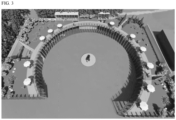
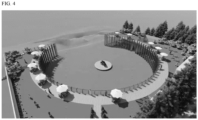
- FIG. 3 and FIG. 4 are diagrams showing an overall shape of the acoustic space building structure according to the present disclosure having the above configuration in a three- dimensional manner.
- the building structure is spaced from, by a constant distance, from the arc center so that a circular courtyard-shaped space with an open top is formed in the central area in the plan view.
- the courtyard space is defined by a wall structure formed by combining the plurality of sound guide blade plates and the sound reflective wall to each other.
- the circular acoustic space with an open top is defined in the central area of the plan view by the sound guide blade plates and the sound reflective wall.
- the reference numerals are omitted to prevent congestion on the drawing.
- the distance from the arc center to each of the sound guide blade plates and the sound reflective wall is preferably in a range of about 15 to 35 m.
- This distance range is set based on a distance between the sound source stage of the central area to the audience on a top face of the rooftop viewing floor, a time for which the sound hits the sound reflective wall and returns to the center, and a distance at which the resonance phenomenon due to the harmony between the original sound and the reflected sound may occur smoothly.
- the distance in a range of 15 to 25 m distance is most appropriate to generate the optimal reverberation sound.
- each of the sound guide blade plate and the sound reflective wall structure may be determined in proportion to the distance from the arc center to the sound reflective wall, and may be in a range of approximately 3 to 8 m.
- FIG. 5 is a schematic diagram showing a sound effect in an acoustic space building structure according to the present disclosure. Referring to FIG. 5 , an action related to the sound effect of the present disclosure will be described.
- the acoustic space 200 is defined in the central area in the plan view of the building so as to be surrounded with the sound reflective wall 20 and the sound guide blade plates 10.
- the sound generated from the central stage is amplified by itself via the sound focusing and resonance caused by the configuration of the sound guide blade plates 10 and the sound reflective wall 20.
- the audience on a top face of the rooftop viewing floor 30 can listen to pure original sound at a satisfactory volume without the separate loudspeaker equipment such as the speaker or the amplifier.
- the sound reflective wall 20 extends in a circle in a plan view having the center point CP on the base bottom face 100 as the arc center as shown in FIG. 1 .
- the reflected sound S1 basically returns toward the stage center where the original sound S0 is generated.
- the sound reflective wall 20 is made of a smooth surface suitable for sound reflection.
- diffused reflection partially occurs on the surface of the sound reflective wall 20, resulting in dispersion of the reflected sounds.
- the sound guide blade plates 10 protrude, by the same predefined length, from the sound reflective wall 20.
- the reflected sounds diffusely reflected from the surface of the sound reflective wall 20 may be guided by the sound guide blade plates 10 in the protruding direction thereof.
- the dispersion of the reflected sounds S1 may be blocked such that the reflected sounds S1 may be concentrated toward the stage center (in accordance with the present disclosure, the action of concentrating the reflected sounds onto the central area is referred to as the sound focusing action).
- the reflected sounds S1 concentrated onto the stage central area as described above encounter the stage original sound S0 and the reflected sounds coming in different directions, such that interference and resonance therebetween occur.
- the resonant sound S2 is generated.
- the resonant sound S2 propagates upwardly of the acoustic space 200 and reaches the audience present on the rooftop viewing floor 30 extending outwardly from the upper portion of the sound reflective wall 20. Therefore, the audience on the rooftop viewing floor 30 may hear the resonant sound S2 and the reverberation sound generated via the sound reflection and resonance inside the acoustic space 200 together with the direct stage original sound S0.
- the audience is able to appreciate the performance based on a three-dimensional, reverberant, and rich sound as in the indoor performance,
- the building structure according to the present disclosure is constructed such that the stage original sound S0 is not immediately diffused to the outside, but is reflected from the sound reflective wall 20, thereby generating the resonant sound S2 inside the acoustic space 200, which in turn is delivered to the audience.
- the sound energy loss may be greatly reduced. Therefore, according to the acoustic space building structure according to the present disclosure, a sufficient volume may be obtained without the sound equipment such as a speaker, so that the audience may enjoy the pure original sound of the stage performance sound.
- the acoustic space 200 surrounded with the sound reflective wall 20 is positioned at a vertical level lower than that of the rooftop viewing floor 30 where the audience views the performance.
- the acoustic space 200 in accordance with the present disclosure may function as a resonator chamber of a musical instrument to act to amplify the original sound of the stage loudly so that the audience on the rooftop viewing floor 30 can hear the sound. Therefore, when the performance sound occurs from the sound source stage 50 of the central area, the performance sound is trapped in the above-mentioned acoustic space 200 and does not escape immediately.
- the performance sound is reflected several times from the sound reflective wall 20
- the sound is amplified to a loud sound based on the sound interference and resonance phenomenon, and is transmitted to the audience on the rooftop viewing floor 30 located above the acoustic space 200.
- the reverberation sound generated due to the repeated sound reflections is continuously transmitted to the audience, the audience can hear the soundly clear and three-dimensional sound in a pure original sound state without using the sound equipment.
- the reverberation sound may be composed of only the reflected sound because of little absorption of the original sound when the sound is reflected.
- the reverberation sound is very resonant, and a reverberation time is prolonged, such that an echo phenomenon (a cave effect) may occur. Therefore, in order to solve this problem, according to the present disclosure, each of the sound guide blade plates 10 connected to the sound reflective wall 20 from which the sound is reflected as described above has the sound absorption ability.
- the sound absorption and the sound reflection may be controlled to produce optimal reverberation sound.
- the sound guide blade plate 10 is made of a material having a higher sound absorption coefficient than that of the sound reflective wall 20.
- a sound absorbing finishing layer made of a sound absorbing finishing material may be attached or coated to or on the surface of the sound guide blade plate 10.
- the building structure according to the present disclosure may overcome the dry and poor sound as a disadvantage of the outdoor performance such that the audience may enjoy the sound with a three-dimensional and rich feeling as in the indoor performance.
- the building structure according to the present disclosure may achieve an appropriate harmony between the sound reflection, the sound absorption, and the sound interference to generate an appropriate resonance and a clear and transparent optimal reverberation sound.
- the present disclosure is related to the field of building and construction, and is applicable to the design and construction of a building structure.
Landscapes
- Engineering & Computer Science (AREA)
- Architecture (AREA)
- Physics & Mathematics (AREA)
- Multimedia (AREA)
- Civil Engineering (AREA)
- Structural Engineering (AREA)
- Acoustics & Sound (AREA)
- Electromagnetism (AREA)
- Building Environments (AREA)
- Reverberation, Karaoke And Other Acoustics (AREA)
Applications Claiming Priority (1)
| Application Number | Priority Date | Filing Date | Title |
|---|---|---|---|
| PCT/KR2020/006668 WO2021235573A1 (ko) | 2020-05-21 | 2020-05-21 | 사운드 포커싱을 통해 음향 장비 없이도 소리의 증폭과 최적 잔향음을 만들어 내는 음향 공간 건축 구조물 |
Publications (4)
| Publication Number | Publication Date |
|---|---|
| EP4155484A1 true EP4155484A1 (de) | 2023-03-29 |
| EP4155484A4 EP4155484A4 (de) | 2023-06-28 |
| EP4155484B1 EP4155484B1 (de) | 2024-09-11 |
| EP4155484C0 EP4155484C0 (de) | 2024-09-11 |
Family
ID=78708590
Family Applications (1)
| Application Number | Title | Priority Date | Filing Date |
|---|---|---|---|
| EP20936565.9A Active EP4155484B1 (de) | 2020-05-21 | 2020-05-21 | Akustische raumbaustruktur zur klangverstärkung und erzeugung eines optimalen hallklangs mittels klangfokussierung ohne klangausrüstung |
Country Status (4)
| Country | Link |
|---|---|
| EP (1) | EP4155484B1 (de) |
| JP (1) | JP7617653B2 (de) |
| CN (1) | CN116134199B (de) |
| WO (1) | WO2021235573A1 (de) |
Families Citing this family (1)
| Publication number | Priority date | Publication date | Assignee | Title |
|---|---|---|---|---|
| CN119063053B (zh) * | 2024-11-05 | 2025-07-08 | 浙江东信电器有限公司 | 一种静音式吊顶取暖器设备 |
Family Cites Families (21)
| Publication number | Priority date | Publication date | Assignee | Title |
|---|---|---|---|---|
| JPS50114838A (de) * | 1974-02-21 | 1975-09-09 | ||
| JPS5913505U (ja) * | 1982-07-17 | 1984-01-27 | 北嶋総合株式会社 | 壁面における吸音調節スリツト装置 |
| JPS6037304A (ja) * | 1983-08-09 | 1985-02-26 | 日本車輌製造株式会社 | コミユニテイスペ−スを有する立体構造物 |
| JPS612516U (ja) * | 1984-06-12 | 1986-01-09 | 古河電気工業株式会社 | 遮音壁体 |
| US4686799A (en) * | 1986-03-17 | 1987-08-18 | Kwake John P | Theatre structure with individual multiple lounges |
| JPH08260738A (ja) * | 1995-03-17 | 1996-10-08 | Kiyonori Kikutake | 多目的建築物の可変壁 |
| KR20000012544A (ko) * | 1999-12-10 | 2000-03-06 | 손희수 | 음향블럭 |
| JP2002138423A (ja) * | 2000-11-06 | 2002-05-14 | Bridgestone Corp | 透光型吸音体 |
| US6915610B2 (en) * | 2001-08-22 | 2005-07-12 | Ssoe, Inc. | Multi-purpose arena |
| KR200295451Y1 (ko) | 2002-08-26 | 2002-11-18 | 강희만 | 야외 잔향 부가 시스템 |
| KR200316692Y1 (ko) | 2003-03-27 | 2003-06-18 | 강희만 | 잔향 부가용 스피커장치 |
| JP2009528086A (ja) * | 2006-02-23 | 2009-08-06 | ファルコンズ トゥリーハウス リミテッド ライアビリティ カンパニー | 円形移動劇場 |
| KR200422496Y1 (ko) * | 2006-05-17 | 2006-07-27 | (주)시공사 | 음향 반사장치 |
| US20100300006A1 (en) * | 2009-05-29 | 2010-12-02 | Cecil Magpuri | Virtual reality dome theater |
| GB2472238B (en) * | 2009-07-29 | 2011-12-28 | Sounds Forms Plc | Sound shell |
| WO2014132280A2 (en) * | 2013-02-26 | 2014-09-04 | Monacchi David | Eco-acoustic theatre |
| CN104047446B (zh) * | 2013-03-15 | 2018-02-09 | 北京时代秀域文化科技有限公司 | 一种通过观众席迴转改变舞台区域和状态的舞台 |
| US10335705B2 (en) * | 2015-12-18 | 2019-07-02 | Tait Towers Manufacturing Llc | Venue trays and method for moving venue trays |
| CN206753133U (zh) * | 2017-01-10 | 2017-12-15 | 上海灿星文化传播有限公司 | 荣耀之桥舞台装置 |
| CN207620446U (zh) * | 2017-10-31 | 2018-07-17 | 北京城建集团有限责任公司 | 一种造型传声的剧院 |
| KR102273431B1 (ko) * | 2019-01-30 | 2021-07-05 | 이형호 | 사운드 포커싱을 통해 음향 장비 없이도 소리의 증폭과 최적 잔향음을 만들어 내는 음향 공간 건축 구조물 |
-
2020
- 2020-05-21 CN CN202080104754.5A patent/CN116134199B/zh active Active
- 2020-05-21 JP JP2022570326A patent/JP7617653B2/ja active Active
- 2020-05-21 EP EP20936565.9A patent/EP4155484B1/de active Active
- 2020-05-21 WO PCT/KR2020/006668 patent/WO2021235573A1/ko not_active Ceased
Also Published As
| Publication number | Publication date |
|---|---|
| EP4155484A4 (de) | 2023-06-28 |
| JP7617653B2 (ja) | 2025-01-20 |
| EP4155484B1 (de) | 2024-09-11 |
| JP2023535119A (ja) | 2023-08-16 |
| CN116134199A (zh) | 2023-05-16 |
| EP4155484C0 (de) | 2024-09-11 |
| WO2021235573A1 (ko) | 2021-11-25 |
| CN116134199B (zh) | 2025-05-09 |
Similar Documents
| Publication | Publication Date | Title |
|---|---|---|
| US20190257079A1 (en) | Special lightweight, durable mounting system for sound foam panel and quick installation process | |
| US8978816B2 (en) | Sound limiting acoustic shell using a hanging acoustic canopy | |
| US20110024225A1 (en) | Sound shell | |
| EP4155484B1 (de) | Akustische raumbaustruktur zur klangverstärkung und erzeugung eines optimalen hallklangs mittels klangfokussierung ohne klangausrüstung | |
| JP2018107678A (ja) | イベントの会場施設及びその設置方法 | |
| KR102273431B1 (ko) | 사운드 포커싱을 통해 음향 장비 없이도 소리의 증폭과 최적 잔향음을 만들어 내는 음향 공간 건축 구조물 | |
| Jinoh et al. | Variable Acoustics in performance venues-A review | |
| Newell | Recording spaces | |
| Orlowski | Acoustics in Architectural design | |
| Shankland | The Development of Architectural Acoustics: The application of the science of acoustics to architectural designs has produced greatly improved halls for both speech and music | |
| Beranek | Acoustics and the concert hall | |
| Adelman-Larsen | Design Principles | |
| Öqvist et al. | Studio Acusticum: a concert hall with variable volume | |
| Kahle et al. | La Philharmonie de Paris concert hall competition, part 1: Acoustic brief | |
| Bacelar | Evolution of acoustical design in football stadia in the last 60 years | |
| Ramakrishna | Acoustical Design and Testing of the Centenary Auditorium of Madras University | |
| Brown | Review of acoustically related design factors for three recent Los Angeles area music studios. | |
| Katunský et al. | ENVIRONMENTAL PROBLEMS OF TEST ROOMS IN MUSICAL CENTERS INFLUENCE ON THE INTERIOR | |
| Skånberg Dahlstedt | Under konstruktion: en återvunnen teater | |
| Katunský et al. | Environmental and Technical Problems of Test Room Spaces in Cultural Buildings | |
| Somerville | Architectural acoustics and the arts | |
| Asselineau et al. | Music and outdoors: are they meant to work together? | |
| Luhr | Meeting for music | |
| Beranek | Acoustics of the Fredric R. Mann Concert Hall, Tel Aviv, Israel | |
| Dunbar | Space Acoustics |
Legal Events
| Date | Code | Title | Description |
|---|---|---|---|
| STAA | Information on the status of an ep patent application or granted ep patent |
Free format text: STATUS: THE INTERNATIONAL PUBLICATION HAS BEEN MADE |
|
| PUAI | Public reference made under article 153(3) epc to a published international application that has entered the european phase |
Free format text: ORIGINAL CODE: 0009012 |
|
| STAA | Information on the status of an ep patent application or granted ep patent |
Free format text: STATUS: REQUEST FOR EXAMINATION WAS MADE |
|
| 17P | Request for examination filed |
Effective date: 20221221 |
|
| AK | Designated contracting states |
Kind code of ref document: A1 Designated state(s): AL AT BE BG CH CY CZ DE DK EE ES FI FR GB GR HR HU IE IS IT LI LT LU LV MC MK MT NL NO PL PT RO RS SE SI SK SM TR |
|
| A4 | Supplementary search report drawn up and despatched |
Effective date: 20230530 |
|
| RIC1 | Information provided on ipc code assigned before grant |
Ipc: E04B 1/82 20060101ALI20230523BHEP Ipc: E04H 3/12 20060101AFI20230523BHEP |
|
| DAV | Request for validation of the european patent (deleted) | ||
| DAX | Request for extension of the european patent (deleted) | ||
| REG | Reference to a national code |
Ref country code: DE Ref legal event code: R079 Free format text: PREVIOUS MAIN CLASS: E04H0003120000 Ipc: E04H0003220000 Ref document number: 602020037747 Country of ref document: DE |
|
| GRAP | Despatch of communication of intention to grant a patent |
Free format text: ORIGINAL CODE: EPIDOSNIGR1 |
|
| STAA | Information on the status of an ep patent application or granted ep patent |
Free format text: STATUS: GRANT OF PATENT IS INTENDED |
|
| RIC1 | Information provided on ipc code assigned before grant |
Ipc: G10K 11/20 20060101ALI20240301BHEP Ipc: E04H 3/30 20060101ALI20240301BHEP Ipc: E04B 1/99 20060101ALI20240301BHEP Ipc: E04H 3/22 20060101AFI20240301BHEP |
|
| INTG | Intention to grant announced |
Effective date: 20240404 |
|
| GRAS | Grant fee paid |
Free format text: ORIGINAL CODE: EPIDOSNIGR3 |
|
| GRAA | (expected) grant |
Free format text: ORIGINAL CODE: 0009210 |
|
| STAA | Information on the status of an ep patent application or granted ep patent |
Free format text: STATUS: THE PATENT HAS BEEN GRANTED |
|
| AK | Designated contracting states |
Kind code of ref document: B1 Designated state(s): AL AT BE BG CH CY CZ DE DK EE ES FI FR GB GR HR HU IE IS IT LI LT LU LV MC MK MT NL NO PL PT RO RS SE SI SK SM TR |
|
| REG | Reference to a national code |
Ref country code: GB Ref legal event code: FG4D |
|
| REG | Reference to a national code |
Ref country code: CH Ref legal event code: EP |
|
| REG | Reference to a national code |
Ref country code: DE Ref legal event code: R096 Ref document number: 602020037747 Country of ref document: DE |
|
| REG | Reference to a national code |
Ref country code: IE Ref legal event code: FG4D |
|
| U01 | Request for unitary effect filed |
Effective date: 20241009 |
|
| U07 | Unitary effect registered |
Designated state(s): AT BE BG DE DK EE FI FR IT LT LU LV MT NL PT RO SE SI Effective date: 20241028 |
|
| PG25 | Lapsed in a contracting state [announced via postgrant information from national office to epo] |
Ref country code: NO Free format text: LAPSE BECAUSE OF FAILURE TO SUBMIT A TRANSLATION OF THE DESCRIPTION OR TO PAY THE FEE WITHIN THE PRESCRIBED TIME-LIMIT Effective date: 20241211 |
|
| PG25 | Lapsed in a contracting state [announced via postgrant information from national office to epo] |
Ref country code: GR Free format text: LAPSE BECAUSE OF FAILURE TO SUBMIT A TRANSLATION OF THE DESCRIPTION OR TO PAY THE FEE WITHIN THE PRESCRIBED TIME-LIMIT Effective date: 20241212 |
|
| PG25 | Lapsed in a contracting state [announced via postgrant information from national office to epo] |
Ref country code: HR Free format text: LAPSE BECAUSE OF FAILURE TO SUBMIT A TRANSLATION OF THE DESCRIPTION OR TO PAY THE FEE WITHIN THE PRESCRIBED TIME-LIMIT Effective date: 20240911 |
|
| PG25 | Lapsed in a contracting state [announced via postgrant information from national office to epo] |
Ref country code: RS Free format text: LAPSE BECAUSE OF FAILURE TO SUBMIT A TRANSLATION OF THE DESCRIPTION OR TO PAY THE FEE WITHIN THE PRESCRIBED TIME-LIMIT Effective date: 20241211 Ref country code: ES Free format text: LAPSE BECAUSE OF FAILURE TO SUBMIT A TRANSLATION OF THE DESCRIPTION OR TO PAY THE FEE WITHIN THE PRESCRIBED TIME-LIMIT Effective date: 20240911 |
|
| PG25 | Lapsed in a contracting state [announced via postgrant information from national office to epo] |
Ref country code: RS Free format text: LAPSE BECAUSE OF FAILURE TO SUBMIT A TRANSLATION OF THE DESCRIPTION OR TO PAY THE FEE WITHIN THE PRESCRIBED TIME-LIMIT Effective date: 20241211 Ref country code: NO Free format text: LAPSE BECAUSE OF FAILURE TO SUBMIT A TRANSLATION OF THE DESCRIPTION OR TO PAY THE FEE WITHIN THE PRESCRIBED TIME-LIMIT Effective date: 20241211 Ref country code: HR Free format text: LAPSE BECAUSE OF FAILURE TO SUBMIT A TRANSLATION OF THE DESCRIPTION OR TO PAY THE FEE WITHIN THE PRESCRIBED TIME-LIMIT Effective date: 20240911 Ref country code: GR Free format text: LAPSE BECAUSE OF FAILURE TO SUBMIT A TRANSLATION OF THE DESCRIPTION OR TO PAY THE FEE WITHIN THE PRESCRIBED TIME-LIMIT Effective date: 20241212 Ref country code: ES Free format text: LAPSE BECAUSE OF FAILURE TO SUBMIT A TRANSLATION OF THE DESCRIPTION OR TO PAY THE FEE WITHIN THE PRESCRIBED TIME-LIMIT Effective date: 20240911 |
|
| PG25 | Lapsed in a contracting state [announced via postgrant information from national office to epo] |
Ref country code: IS Free format text: LAPSE BECAUSE OF FAILURE TO SUBMIT A TRANSLATION OF THE DESCRIPTION OR TO PAY THE FEE WITHIN THE PRESCRIBED TIME-LIMIT Effective date: 20250111 |
|
| PG25 | Lapsed in a contracting state [announced via postgrant information from national office to epo] |
Ref country code: SM Free format text: LAPSE BECAUSE OF FAILURE TO SUBMIT A TRANSLATION OF THE DESCRIPTION OR TO PAY THE FEE WITHIN THE PRESCRIBED TIME-LIMIT Effective date: 20240911 |
|
| PG25 | Lapsed in a contracting state [announced via postgrant information from national office to epo] |
Ref country code: PL Free format text: LAPSE BECAUSE OF FAILURE TO SUBMIT A TRANSLATION OF THE DESCRIPTION OR TO PAY THE FEE WITHIN THE PRESCRIBED TIME-LIMIT Effective date: 20240911 Ref country code: CZ Free format text: LAPSE BECAUSE OF FAILURE TO SUBMIT A TRANSLATION OF THE DESCRIPTION OR TO PAY THE FEE WITHIN THE PRESCRIBED TIME-LIMIT Effective date: 20240911 |
|
| PG25 | Lapsed in a contracting state [announced via postgrant information from national office to epo] |
Ref country code: SK Free format text: LAPSE BECAUSE OF FAILURE TO SUBMIT A TRANSLATION OF THE DESCRIPTION OR TO PAY THE FEE WITHIN THE PRESCRIBED TIME-LIMIT Effective date: 20240911 |
|
| U20 | Renewal fee for the european patent with unitary effect paid |
Year of fee payment: 6 Effective date: 20250520 |
|
| PLBE | No opposition filed within time limit |
Free format text: ORIGINAL CODE: 0009261 |
|
| STAA | Information on the status of an ep patent application or granted ep patent |
Free format text: STATUS: NO OPPOSITION FILED WITHIN TIME LIMIT |
|
| 26N | No opposition filed |
Effective date: 20250612 |
|
| REG | Reference to a national code |
Ref country code: CH Ref legal event code: H13 Free format text: ST27 STATUS EVENT CODE: U-0-0-H10-H13 (AS PROVIDED BY THE NATIONAL OFFICE) Effective date: 20251223 |
|
| PG25 | Lapsed in a contracting state [announced via postgrant information from national office to epo] |
Ref country code: CH Free format text: LAPSE BECAUSE OF NON-PAYMENT OF DUE FEES Effective date: 20250531 |
|
| GBPC | Gb: european patent ceased through non-payment of renewal fee |
Effective date: 20250521 |
|
| PG25 | Lapsed in a contracting state [announced via postgrant information from national office to epo] |
Ref country code: MC Free format text: LAPSE BECAUSE OF FAILURE TO SUBMIT A TRANSLATION OF THE DESCRIPTION OR TO PAY THE FEE WITHIN THE PRESCRIBED TIME-LIMIT Effective date: 20240911 |
|
| PG25 | Lapsed in a contracting state [announced via postgrant information from national office to epo] |
Ref country code: GB Free format text: LAPSE BECAUSE OF NON-PAYMENT OF DUE FEES Effective date: 20250521 |
|
| PG25 | Lapsed in a contracting state [announced via postgrant information from national office to epo] |
Ref country code: IE Free format text: LAPSE BECAUSE OF NON-PAYMENT OF DUE FEES Effective date: 20250521 |