EP4155003A1 - Bending system and method for using same - Google Patents
Bending system and method for using same Download PDFInfo
- Publication number
- EP4155003A1 EP4155003A1 EP21808123.0A EP21808123A EP4155003A1 EP 4155003 A1 EP4155003 A1 EP 4155003A1 EP 21808123 A EP21808123 A EP 21808123A EP 4155003 A1 EP4155003 A1 EP 4155003A1
- Authority
- EP
- European Patent Office
- Prior art keywords
- illumination
- illuminations
- illumination unit
- pallet
- predetermined setting
- Prior art date
- Legal status (The legal status is an assumption and is not a legal conclusion. Google has not performed a legal analysis and makes no representation as to the accuracy of the status listed.)
- Granted
Links
Images








Classifications
-
- F—MECHANICAL ENGINEERING; LIGHTING; HEATING; WEAPONS; BLASTING
- F21—LIGHTING
- F21V—FUNCTIONAL FEATURES OR DETAILS OF LIGHTING DEVICES OR SYSTEMS THEREOF; STRUCTURAL COMBINATIONS OF LIGHTING DEVICES WITH OTHER ARTICLES, NOT OTHERWISE PROVIDED FOR
- F21V21/00—Supporting, suspending, or attaching arrangements for lighting devices; Hand grips
- F21V21/14—Adjustable mountings
- F21V21/30—Pivoted housings or frames
-
- B—PERFORMING OPERATIONS; TRANSPORTING
- B21—MECHANICAL METAL-WORKING WITHOUT ESSENTIALLY REMOVING MATERIAL; PUNCHING METAL
- B21D—WORKING OR PROCESSING OF SHEET METAL OR METAL TUBES, RODS OR PROFILES WITHOUT ESSENTIALLY REMOVING MATERIAL; PUNCHING METAL
- B21D5/00—Bending sheet metal along straight lines, e.g. to form simple curves
- B21D5/02—Bending sheet metal along straight lines, e.g. to form simple curves on press brakes without making use of clamping means
- B21D5/0281—Workpiece supporting devices
-
- B—PERFORMING OPERATIONS; TRANSPORTING
- B21—MECHANICAL METAL-WORKING WITHOUT ESSENTIALLY REMOVING MATERIAL; PUNCHING METAL
- B21D—WORKING OR PROCESSING OF SHEET METAL OR METAL TUBES, RODS OR PROFILES WITHOUT ESSENTIALLY REMOVING MATERIAL; PUNCHING METAL
- B21D43/00—Feeding, positioning or storing devices combined with, or arranged in, or specially adapted for use in connection with, apparatus for working or processing sheet metal, metal tubes or metal profiles; Associations therewith of cutting devices
- B21D43/003—Positioning devices
-
- B—PERFORMING OPERATIONS; TRANSPORTING
- B21—MECHANICAL METAL-WORKING WITHOUT ESSENTIALLY REMOVING MATERIAL; PUNCHING METAL
- B21D—WORKING OR PROCESSING OF SHEET METAL OR METAL TUBES, RODS OR PROFILES WITHOUT ESSENTIALLY REMOVING MATERIAL; PUNCHING METAL
- B21D43/00—Feeding, positioning or storing devices combined with, or arranged in, or specially adapted for use in connection with, apparatus for working or processing sheet metal, metal tubes or metal profiles; Associations therewith of cutting devices
- B21D43/20—Storage arrangements; Piling or unpiling
-
- B—PERFORMING OPERATIONS; TRANSPORTING
- B21—MECHANICAL METAL-WORKING WITHOUT ESSENTIALLY REMOVING MATERIAL; PUNCHING METAL
- B21D—WORKING OR PROCESSING OF SHEET METAL OR METAL TUBES, RODS OR PROFILES WITHOUT ESSENTIALLY REMOVING MATERIAL; PUNCHING METAL
- B21D5/00—Bending sheet metal along straight lines, e.g. to form simple curves
- B21D5/002—Positioning devices
-
- B—PERFORMING OPERATIONS; TRANSPORTING
- B21—MECHANICAL METAL-WORKING WITHOUT ESSENTIALLY REMOVING MATERIAL; PUNCHING METAL
- B21D—WORKING OR PROCESSING OF SHEET METAL OR METAL TUBES, RODS OR PROFILES WITHOUT ESSENTIALLY REMOVING MATERIAL; PUNCHING METAL
- B21D5/00—Bending sheet metal along straight lines, e.g. to form simple curves
- B21D5/02—Bending sheet metal along straight lines, e.g. to form simple curves on press brakes without making use of clamping means
- B21D5/0209—Tools therefor
-
- B—PERFORMING OPERATIONS; TRANSPORTING
- B25—HAND TOOLS; PORTABLE POWER-DRIVEN TOOLS; MANIPULATORS
- B25J—MANIPULATORS; CHAMBERS PROVIDED WITH MANIPULATION DEVICES
- B25J11/00—Manipulators not otherwise provided for
- B25J11/005—Manipulators for mechanical processing tasks
-
- F—MECHANICAL ENGINEERING; LIGHTING; HEATING; WEAPONS; BLASTING
- F21—LIGHTING
- F21S—NON-PORTABLE LIGHTING DEVICES; SYSTEMS THEREOF; VEHICLE LIGHTING DEVICES SPECIALLY ADAPTED FOR VEHICLE EXTERIORS
- F21S2/00—Systems of lighting devices, not provided for in main groups F21S4/00 - F21S10/00 or F21S19/00, e.g. of modular construction
-
- F—MECHANICAL ENGINEERING; LIGHTING; HEATING; WEAPONS; BLASTING
- F21—LIGHTING
- F21V—FUNCTIONAL FEATURES OR DETAILS OF LIGHTING DEVICES OR SYSTEMS THEREOF; STRUCTURAL COMBINATIONS OF LIGHTING DEVICES WITH OTHER ARTICLES, NOT OTHERWISE PROVIDED FOR
- F21V21/00—Supporting, suspending, or attaching arrangements for lighting devices; Hand grips
- F21V21/34—Supporting elements displaceable along a guiding element
-
- F—MECHANICAL ENGINEERING; LIGHTING; HEATING; WEAPONS; BLASTING
- F21—LIGHTING
- F21W—INDEXING SCHEME ASSOCIATED WITH SUBCLASSES F21K, F21L, F21S and F21V, RELATING TO USES OR APPLICATIONS OF LIGHTING DEVICES OR SYSTEMS
- F21W2131/00—Use or application of lighting devices or systems not provided for in codes F21W2102/00-F21W2121/00
- F21W2131/40—Lighting for industrial, commercial, recreational or military use
- F21W2131/403—Lighting for industrial, commercial, recreational or military use for machines
-
- F—MECHANICAL ENGINEERING; LIGHTING; HEATING; WEAPONS; BLASTING
- F21—LIGHTING
- F21Y—INDEXING SCHEME ASSOCIATED WITH SUBCLASSES F21K, F21L, F21S and F21V, RELATING TO THE FORM OR THE KIND OF THE LIGHT SOURCES OR OF THE COLOUR OF THE LIGHT EMITTED
- F21Y2105/00—Planar light sources
- F21Y2105/10—Planar light sources comprising a two-dimensional [2D] array of point-like light-generating elements
- F21Y2105/14—Planar light sources comprising a two-dimensional [2D] array of point-like light-generating elements characterised by the overall shape of the two-dimensional [2D] array
- F21Y2105/16—Planar light sources comprising a two-dimensional [2D] array of point-like light-generating elements characterised by the overall shape of the two-dimensional [2D] array square or rectangular, e.g. for light panels
-
- F—MECHANICAL ENGINEERING; LIGHTING; HEATING; WEAPONS; BLASTING
- F21—LIGHTING
- F21Y—INDEXING SCHEME ASSOCIATED WITH SUBCLASSES F21K, F21L, F21S and F21V, RELATING TO THE FORM OR THE KIND OF THE LIGHT SOURCES OR OF THE COLOUR OF THE LIGHT EMITTED
- F21Y2115/00—Light-generating elements of semiconductor light sources
- F21Y2115/10—Light-emitting diodes [LED]
-
- G—PHYSICS
- G05—CONTROLLING; REGULATING
- G05B—CONTROL OR REGULATING SYSTEMS IN GENERAL; FUNCTIONAL ELEMENTS OF SUCH SYSTEMS; MONITORING OR TESTING ARRANGEMENTS FOR SUCH SYSTEMS OR ELEMENTS
- G05B2219/00—Program-control systems
- G05B2219/30—Nc systems
- G05B2219/40—Robotics, robotics mapping to robotics vision
- G05B2219/40052—Deform, bend flexible material
Definitions
- the present invention relates to a bending system that automatically bends a plate-shaped workpiece and a method for using the same.
- the bending system includes a press brake that bends a workpiece.
- a bending robot that assists in bending the workpiece is provided between the press brake and a predetermined setting area that is arranged in front of the press brake.
- the bending robot includes a robot hand that holds the workpiece on a pallet set in the predetermined setting area.
- a camera as an image pickup unit that picks up an image of the workpiece on the pallet from a vertically upper direction is provided above the predetermined setting area.
- a first illumination unit that irradiates an image pickup area of the camera with an illumination beam is provided in the vicinity of the left side of the predetermined setting area.
- a second illumination unit that irradiates the image pickup area of the camera with an illumination beam is provided in the vicinity of the right side of the predetermined setting area.
- the bending system includes a numerical control device that controls the press brake, a robot control device that controls the bending robot, and an image processing device that performs image processing to a picked-up image from the camera.
- the image processing device detects a location of the workpiece on the palette based on the picked-up image from the camera. Based on the detected location of the workpiece, the robot control device controls the bending robot such that the robot hand holds a predetermined portion of the workpiece. Therefore, even if the workpiece is not placed accurately at a predetermined position on the pallet, it is possible to sufficiently ensure the processing accuracy of the bending by appropriately operating the bending robot.
- the camera is located above the predetermined setting area and is not sufficiently separated from the predetermined setting area.
- the two illumination units are located in the vicinity of the predetermined setting area and are not sufficiently separated from the predetermined setting area.
- a bending system includes a bending robot provided between a press brake and a predetermined setting area arranged in front of the press brake, including a robot hand for holding a workpiece on a pallet set in the predetermined setting area, and configured to assist in bending the workpiece, and an image pickup unit provided above and anterior to the predetermined setting area and configured to pick up an image of the workpiece on the pallet from an oblique upper direction.
- the bending system includes a first illumination unit erected on a left front side of the predetermined setting area and configured to irradiate an image pickup area of the image pickup unit with an illumination beam, and a second illumination unit erected on a right front side of the predetermined setting area and configured to irradiate the image pickup area of the image pickup unit with the illumination beam.
- the first illumination unit includes a plurality of first illuminations for irradiation of illumination beams in a right obliquely downward direction, and is configured such that an irradiation direction of each of the first illuminations is adjustable so that an entire area on the pallet is irradiated with the illumination beams from the plurality of first illuminations.
- the second illumination unit includes a plurality of second illuminations for irradiation of illumination beams in a left obliquely downward direction, and is configured such that an irradiation direction of each of the second illuminations is adjustable so that the entire area on the pallet is irradiated with the illumination beams from the plurality of second illuminations.
- the image pickup unit since the image pickup unit is located above and anterior to the predetermined setting area, the image pickup unit can be sufficiently separated from the predetermined setting area. Since the first illumination unit is located on the left front side of the predetermined setting area and the second illumination unit is located on the right front side of the predetermined setting area, the first illumination unit and the second illumination unit can be sufficiently separated from the predetermined setting area. Therefore, the workpiece held by the part of the bending robot or the robot hand does not interfere with the image pickup unit, the first illumination unit, or the second illumination unit. Therefore, the operating range of the bending robot is not limited by the image pickup unit and the like.
- a method for using a bending system according to a third embodiment is a method for using the bending system according to the second embodiment. Then, in a state in which an entire area on the pallet is covered with an adjustment sheet, the irradiation direction of each of the first illuminations is adjusted such that a position on the adjustment sheet is irradiated with a visible beam from a laser pointer of an adjustment jig mounted to each of the first illuminations, the position on the adjustment sheet corresponding to an irradiation range of a respective one of the first illuminations.
- an irradiation direction of each of the second illuminations is adjusted such that a position on the adjustment sheet is irradiated with the visible beam from the laser pointer of the adjustment jig mounted to each of the second illuminations, the position on the adjustment sheet corresponding to an irradiation range of a respective one of the second illuminations.
- a method for using a bending system according to a fourth embodiment is a method for using the bending system according to the second embodiment. Then, when the image pickup unit picks up an image of the workpiece on the pallet from the oblique upper direction, an illumination operation of the first illumination unit is executed so that the entire area on the pallet is irradiated with the illumination beams from the plurality of first illuminations. Further, an illumination operation of the second illumination unit is executed so that the entire area on the pallet is irradiated with the illumination beams from the plurality of second illuminations.
- FF indicates a forward direction
- FR indicates a backward direction
- L indicates a left direction
- R indicates a right direction
- U indicates an upper direction
- D indicates a downward direction.
- a bending system 10 is a processing system that automatically bends a plate-shaped workpiece (sheet metal) W.
- the bending system 10 includes a press brake 12 that bends the workpiece W through cooperation between a punch tool (not shown) and a die tool (not shown).
- a predetermined setting area (carrying-in area) SA for a pallet 14 to be set is formed in front of the press brake 12.
- the pallet 14 supports the workpiece W.
- the carrying-in area SA for carrying in the workpiece W into the bending system 10 via the pallet 14 is formed.
- the pallet 14 is set in the predetermined setting area SA by a fork lifter (not shown) or a hand lifter (not shown).
- a carrying-out area TA for carrying out a bent product from the bending system 10 via a product pallet (not shown) is formed.
- a plurality of pedestals 16 that support the pallet 14 are provided on a floor surface of the predetermined setting area SA via a plurality of low head bolts 18 and a plurality of anchors (not shown).
- a plurality of half-split shims (not shown) for adjusting a height location of each of the pedestals 16 are interposed between each of the pedestals 16 and the floor surface. Therefore, by adjusting the height location of each of the pedestals 16, it is possible to sufficiently ensure flatness of an upper surface of the pallet 14 set in the predetermined setting area SA.
- a guide frame 20 extending in the lateral direction is provided between the press brake 12 and the predetermined setting area SA.
- a bending robot 22, which assists in bending the workpiece W, is provided to the guide frame 20 in such a manner as to be movable in the lateral direction.
- the bending robot 22 is provided between the press brake 12 and the predetermined setting area SA in such a manner as to be movable via the guide frame 20 in the lateral direction.
- the bending robot 22 has a known configuration shown in Patent Literature 2, for example, and includes an articulated robot arm 24.
- the bending robot 22 includes a robot hand 26 that is provided at the distal end of the robot arm 24 in an installable and removeable manner.
- the robot hand 26 sucks the workpiece W on the pallet 14 set in the predetermined setting area SA.
- the robot hand 26 may include a gripper (not shown) that grips the end portion of the workpiece W.
- An L-shaped support column 28 is erected on the floor surface on a left front side of the predetermined setting area SA, and the support column 28 includes a vertical portion (a perpendicular portion) 28a and a horizontal portion 28b that is provided above the vertical portion 28a.
- a monocular camera 30 is provided as an image pickup unit that picks up, from an oblique upper direction, an image of the workpiece W on the pallet 14 set in the predetermined setting area SA.
- the camera 30 is provided above and anterior to the predetermined setting area SA via the support column 28.
- the camera 30 includes a CCD (Charge Coupled Device) or a CMOS (Complementary Metal Oxide Semiconductor) as an image pickup element. Note that a stereo camera (not shown) may be used in lieu of the monocular camera 30.
- a first illumination stand 32 as a first illumination unit that irradiates an image pickup area of the camera 30 with an illumination beam, is erected on the left front side of the predetermined setting area SA.
- the first illumination stand 32 is arranged to be inclined with respect to the lateral direction so that a right end side thereof is located more forward than a left end side thereof. Then, the specific contents of the respective constituent members of the first illumination stand 32 are as follows.
- a first support frame 34 is erected on the left front side of the predetermined setting area SA.
- the first support frame 34 includes a plurality of (three in the present embodiment) first beam members 36 that extend in the horizontal direction.
- Each of the first beam members 36 is provided with an inverted U-shaped first bracket 38 via a mounting bolt 40.
- the first bracket 38 is rotatable around an axial center of the mounting bolt 40 that is a vertical axial center.
- a first illumination 42 for irradiation of the illumination beam in a right obliquely downward direction is provided to each of the first brackets 38 via a mounting bolt 44.
- the first illumination stand 32 includes a plurality of (13 in the present embodiment) first illuminations 42.
- the illumination beams from the plurality of first illuminations 42 cast shadows on the right and rear edge portions (contour portions) of the workpiece W on the pallet 14 set in the predetermined setting area SA to clarify those edge portions.
- each of the first illuminations 42 is rotatable around the axial center of the mounting bolt 44 that is a horizontal axial center.
- Each of the first illuminations 42 is rotatable around the axial center of the mounting bolt 40 integrally with the first bracket 38.
- a circular arc slit 38s is formed on each side surface of each of the first brackets 38.
- a movable bolt 46 as a movable element is provided on each side surface of each of the first illuminations 42, and each of the movable bolts 46 moves in a state of being guided to the slit 38s of each of the first brackets 38.
- each of the first illuminations 42 includes a rectangular box-shaped illumination main body 48 provided to each of the first brackets 38 and whose front side (irradiation side) is open, an acrylic panel 50 provided on the front side of the illumination main body 48, and a plurality of light emitting diodes (LEDs) 52 provided in the illumination main body 48.
- LEDs light emitting diodes
- each of the first illuminations 42 is configured to be rotatable around the two orthogonal axial centers.
- the irradiation direction of each of the first illuminations 42 is configured to be adjustable so that an entire area on the pallet 14 is irradiated with the illumination beams from the plurality of first illuminations 42 (see Figure 9 ).
- the two orthogonal axial centers refer to a horizontal axial center and a vertical axial center.
- each of the first illuminations 42 is attached with a numerical subscript for identification (42 1 to 42 13 ).
- An irradiation range C of each of the first illuminations 42 is attached with a numerical subscript for identification (C 1 to C 13 ).
- the adjustment jig 54 includes a jig main body 56 that can be magnetically attached to an appropriate location of each of the illumination main bodies 48, and a laser pointer 58 that is provided to the jig main body 56 and emits a visible beam.
- a second illumination stand 60 as a second illumination unit that irradiates the image pickup area of the camera 30 with the illumination beam, is erected on the right front side of the predetermined setting area SA.
- the second illumination stand 60 is arranged to be inclined with respect to the lateral direction so that a left end side thereof is located more forward than a right end side thereof.
- the second illumination stand 60 is separated from the first illumination stand 32 in the lateral direction, and a taking-in and out passage EG for taking in and out the pallet 14 with respect to the predetermined setting area SA is formed between the first illumination stand 32 and the second illumination stand 60. Then, the specific contents of the respective constituent members of the second illumination stand 60 are as follows.
- a second support frame 62 is erected on the right front side of the predetermined setting area SA.
- the second support frame 62 includes a plurality of (three in the present embodiment) second beam members 64 that extend in the horizontal direction.
- Each of the second beam members 64 is provided with an inverted U-shaped second bracket 66 via a mounting bolt 68.
- the second bracket 66 is rotatable around the axial center of the mounting bolt 68 that is a vertical axial center.
- a second illumination 70 for irradiation of the illumination beam in a left obliquely downward direction is provided to each of the second brackets 66 via a mounting bolt 72.
- the second illumination stand 60 includes a plurality of (13 in the present embodiment) second illuminations 70.
- the plurality of second illuminations 70 cast shadows on the left and rear edge portions (contour portions) of the workpiece W on the pallet 14 set in the predetermined setting area SA to clarify those edge portions.
- each of the second illuminations 70 is rotatable around the axial center of the mounting bolt 72 that is a horizontal axial center.
- Each of the second illuminations 70 is rotatable around the axial center of the mounting bolt 68 integrally with the second bracket 66.
- a circular arc slit 66s is formed on each side surface of each of the second brackets 66.
- a movable bolt 74 as a movable element is provided on each side surface of each of the second illuminations 70, and each of the movable bolts 74 moves in a state of being guided to the slit 66s of each of the second brackets 66.
- each of the second illuminations 70 includes a rectangular box-shaped illumination main body 76 provided to each of the second brackets 66 and whose front side (irradiation side) is open, an acrylic panel 78 provided on the front side of the illumination main body 76, and a plurality of light emitting diodes (LEDs) 80 provided in the illumination main body 76.
- LEDs light emitting diodes
- each of the second illuminations 70 is configured to be rotatable around the two orthogonal axial centers.
- the irradiation direction of each of the second illuminations 70 is configured to be adjustable so that the entire area on the pallet 14 set in the predetermined setting area SA is irradiated with the illumination beams from the plurality of second illuminations 70 (See Figure 12 ).
- each of the second illuminations 70 is attached with a numerical subscript for identification (70 1 to 70 13 ).
- the irradiation range C of each of the second illuminations 70 is attached with a numerical subscript for identification (C 1 to C 13 ).
- the adjustment jig 54 is used as described above.
- the jig main body 56 of the adjustment jig 54 can be magnetically attached to an appropriate location of each of the illumination main bodies 76.
- a first guard 82 that protects the first illumination stand 32 is provided in the vicinity of the right side of the first illumination stand 32.
- the first guard 82 is arranged to be along the first illumination stand 32.
- a second guard 84 that protects the second illumination stand 60 is provided in the vicinity of the left side of the second illumination stand 60.
- the second guard 84 is arranged to be along the second illumination stand 60.
- a safety fence 86 for ensuring the safety of the bending is provided around most of the bending system 10.
- the safety fence 86 includes a plurality of doors (not shown) for allowing the fork lifter or the hand lifter to pass through.
- the bending system 10 includes a numerical control device (a main control device) that controls the press brake 12, and a robot control device that controls the bending robot 22.
- the bending system 10 includes an illumination control device that controls the first illumination stand 32 and the second illumination stand 60, and an image processing device that performs image processing to a picked-up image of the camera 30.
- the illumination control device separately executes an irradiation operation of the illumination beams from the plurality of first illuminations 42 and an irradiation operation of the illumination beams from the plurality of second illuminations 70.
- the image processing device corrects a distortion of the picked-up image of the camera 30, which is caused by the inclination of the image pickup direction of the camera 30 with respect to the vertical direction.
- the image processing device detects the location of the workpiece W on the pallet 14 based on the corrected picked-up image of the camera 30.
- the robot control device controls the bending robot 22 so that the robot hand 26 holds a predetermined portion of the workpiece W based on the detected location of the workpiece W. Therefore, even if the workpiece W is not placed accurately at a predetermined position on the pallet 14, it is possible to sufficiently ensure the processing accuracy of the bending by appropriately operating the bending robot 22.
- each of the first illuminations 42 is attached with a numerical subscript for identification (42 1 to 42 13 ).
- the position P corresponding to the irradiation range C (C 1 to C 13 ) of each of the first illuminations 42 (42 1 to 42 13 ) is attached with a numerical subscript for identification (P 1 to P 13 ).
- each of the second illuminations 70 is attached with a numerical subscript for identification (70 1 to 70 13 ).
- the position P corresponding to the irradiation range C (C 1 to C 13 ) of each of the second illuminations 70 (70 1 to 70 13 ) is attached with a numerical subscript for identification (P 1 to P 13 ).
- an illumination operation of the second illumination stand 60 is executed so that the entire area on the pallet 14 is irradiated with the illumination beams from the plurality of second illuminations 70. Then, shadows can be casted on the left and rear edge portions of the workpiece W on the pallet 14 to clarify those edge portions. Since the illumination beams from the plurality of second illuminations 70 are directed in the left obliquely downward direction, the end surfaces of the right and front edge portions of the workpiece W on the pallet 14 can be recognized by the camera 30. Therefore, it is not necessary to cast shadows on these edges.
- the execution timings of the illumination operation of the first illumination stand 32 and the illumination operation of the second illumination stand 60 are staggered. By clarifying the right, left, and rear edge portions of the workpiece W on the pallet 14, the image processing device can easily detect the location of the workpiece W by pattern matching.
- the camera 30 since the camera 30 is located above and anterior to the predetermined setting area SA, the camera 30 can be sufficiently separated from the predetermined setting area SA. Since the first illumination stand 32 is located on the left front side of the predetermined setting area SA and the second illumination stand 60 is located on the right front side of the predetermined setting area SA, the first illumination stand 32 and the second illumination stand 60 can be sufficiently separated from the predetermined setting area SA. Therefore, the workpiece W sucked by a part of the bending robot 22 or the robot hand 26 does not interfere with the camera 30, the first illumination stand 32, and the second illumination stand 60. In other words, the operating range of the bending robot 22 that sucks the workpiece W is not limited by the camera 30 or the like. Therefore, according to the first embodiment, it is possible to increase the degree of freedom of the bending of the bending system 10 while sufficiently ensuring the processing accuracy of the bending.
- the first illumination stand 32 is arranged to be inclined with respect to the lateral direction so that the right end side thereof is located more forward than the left end side thereof.
- the second illumination stand 60 is arranged to be inclined with respect to the lateral direction so that the left end side thereof is located more forward than the right end side thereof.
- a taking-in and out passage EG is formed between the first illumination stand 32 and the second illumination stand 60. Therefore, it is possible to sufficiently ensure a worker flow line in the vicinity of the predetermined setting area SA while allowing the pallet 14 to be taken in and out with respect to the predetermined setting area SA. Therefore, according to the first embodiment, the workability and operability of the bending system 10 can be improved.
- the first guard 82 is provided in the vicinity of the right side of the first illumination stand 32, and the second guard 84 is provided in the vicinity of the left side of the second illumination stand 60. Therefore, according to the first embodiment, damage to the first illumination stand 32 or the second illumination stand 60 due to contact with the fork lifter or the hand lifter can be sufficiently prevented.
- a bending system 88 As shown in Figures 15 to 17 , a bending system 88 according to a second embodiment automatically bends the workpiece W in the same manner as the bending system 10 of the first embodiment (see Figure 1 ).
- the bending system 88 has the same configurations as the bending system 10 except for a part, and of the configurations of the bending system 88, a configuration and the like different from those of the bending system 10 will be described. Note that of a plurality of constituent members of the bending system 88, those corresponding to the constituent members of the bending system 10 are denoted by the same reference numerals in the drawings.
- the first illumination stand 32 that irradiates the image pickup area of the camera 30 with the illumination beam is erected on the left front side of the predetermined setting area SA.
- the first illumination stand 32 is arranged in parallel along the lateral direction.
- a second illumination stand 60 that irradiates the image pickup area of the camera 30 with the illumination beam is erected on the right front side of the predetermined setting area SA.
- the second illumination stand 60 is arranged in parallel along the lateral direction.
- the first illumination stand 32 and the second illumination stand 60 may each has a caster attached with a brake (not shown).
- a first guard (not shown) that protects the first illumination stand 32 may be provided in the vicinity of the first illumination stand 32.
- a second guard (not shown) that protects the second illumination stand 60 may be provided in the vicinity of the second illumination stand 60.
- the first illumination stand 32 and the second illumination stand 60 can be sufficiently separated from the predetermined setting area SA. Therefore, the workpiece W sucked by the part of the bending robot 22 or the robot hand 26 does not interfere with the camera 30, the first illumination stand 32, and the second illumination stand 60. In other words, the operating range of the bending robot 22 that sucks the workpiece W is not limited by the camera 30 or the like. Therefore, according to the second embodiment, it is possible to increase the degree of freedom of the bending of the bending system 88 while sufficiently ensuring the processing accuracy of the bending.
Landscapes
- Engineering & Computer Science (AREA)
- Mechanical Engineering (AREA)
- General Engineering & Computer Science (AREA)
- Robotics (AREA)
- Bending Of Plates, Rods, And Pipes (AREA)
Abstract
Description
- The present invention relates to a bending system that automatically bends a plate-shaped workpiece and a method for using the same.
- In recent years, bending systems have become widespread in the field of sheet metal processing. Hereinafter, the configuration and the like of the bending system will be briefly described (see Patent Literature 1).
- The bending system includes a press brake that bends a workpiece. A bending robot that assists in bending the workpiece is provided between the press brake and a predetermined setting area that is arranged in front of the press brake. The bending robot includes a robot hand that holds the workpiece on a pallet set in the predetermined setting area. Further, above the predetermined setting area, a camera as an image pickup unit that picks up an image of the workpiece on the pallet from a vertically upper direction is provided. A first illumination unit that irradiates an image pickup area of the camera with an illumination beam is provided in the vicinity of the left side of the predetermined setting area. A second illumination unit that irradiates the image pickup area of the camera with an illumination beam is provided in the vicinity of the right side of the predetermined setting area.
- The bending system includes a numerical control device that controls the press brake, a robot control device that controls the bending robot, and an image processing device that performs image processing to a picked-up image from the camera. The image processing device detects a location of the workpiece on the palette based on the picked-up image from the camera. Based on the detected location of the workpiece, the robot control device controls the bending robot such that the robot hand holds a predetermined portion of the workpiece. Therefore, even if the workpiece is not placed accurately at a predetermined position on the pallet, it is possible to sufficiently ensure the processing accuracy of the bending by appropriately operating the bending robot.
- Note that as related prior arts, in addition to
Patent Literature 1, there are those shown in Patent Literatures 2 to 4. -
- Patent Literature 1:
Japanese Patent Application Laid-Open Publication No. 2018-120388 - Patent Literature 2:
Japanese Patent Application Laid-Open Publication No. 2017-124469 - Patent Literature 3:
Japanese Patent Application Laid-Open Publication No. 2015-13303 - Patent Literature 4:
Japanese Patent Application Laid-Open Publication No. 2019-14027 - Now, in the conventional bending system, the camera is located above the predetermined setting area and is not sufficiently separated from the predetermined setting area. The two illumination units are located in the vicinity of the predetermined setting area and are not sufficiently separated from the predetermined setting area. As a result, in order to prevent a part of the bending robot and the workpiece held by the robot hand from interfering with the camera or the like, the operating range of the bending robot is limited, which often results in a case in which it is impossible to bend the workpiece. In other words, there is a problem that it is difficult to increase the degree of freedom of the processing of the bending system while sufficiently ensuring the processing accuracy of the bending.
- A bending system according to a first embodiment of the present invention includes a bending robot provided between a press brake and a predetermined setting area arranged in front of the press brake, including a robot hand for holding a workpiece on a pallet set in the predetermined setting area, and configured to assist in bending the workpiece, and an image pickup unit provided above and anterior to the predetermined setting area and configured to pick up an image of the workpiece on the pallet from an oblique upper direction. The bending system according to the present embodiment includes a first illumination unit erected on a left front side of the predetermined setting area and configured to irradiate an image pickup area of the image pickup unit with an illumination beam, and a second illumination unit erected on a right front side of the predetermined setting area and configured to irradiate the image pickup area of the image pickup unit with the illumination beam.
- In a bending system according to a second embodiment, in addition to the configuration of the bending system according to the first embodiment, the first illumination unit includes a plurality of first illuminations for irradiation of illumination beams in a right obliquely downward direction, and is configured such that an irradiation direction of each of the first illuminations is adjustable so that an entire area on the pallet is irradiated with the illumination beams from the plurality of first illuminations. Further, the second illumination unit includes a plurality of second illuminations for irradiation of illumination beams in a left obliquely downward direction, and is configured such that an irradiation direction of each of the second illuminations is adjustable so that the entire area on the pallet is irradiated with the illumination beams from the plurality of second illuminations.
- According to the configurations of the bending system according to the first embodiment and the second embodiment, as described above, since the image pickup unit is located above and anterior to the predetermined setting area, the image pickup unit can be sufficiently separated from the predetermined setting area. Since the first illumination unit is located on the left front side of the predetermined setting area and the second illumination unit is located on the right front side of the predetermined setting area, the first illumination unit and the second illumination unit can be sufficiently separated from the predetermined setting area. Therefore, the workpiece held by the part of the bending robot or the robot hand does not interfere with the image pickup unit, the first illumination unit, or the second illumination unit. Therefore, the operating range of the bending robot is not limited by the image pickup unit and the like.
- A method for using a bending system according to a third embodiment is a method for using the bending system according to the second embodiment. Then, in a state in which an entire area on the pallet is covered with an adjustment sheet, the irradiation direction of each of the first illuminations is adjusted such that a position on the adjustment sheet is irradiated with a visible beam from a laser pointer of an adjustment jig mounted to each of the first illuminations, the position on the adjustment sheet corresponding to an irradiation range of a respective one of the first illuminations. Further, an irradiation direction of each of the second illuminations is adjusted such that a position on the adjustment sheet is irradiated with the visible beam from the laser pointer of the adjustment jig mounted to each of the second illuminations, the position on the adjustment sheet corresponding to an irradiation range of a respective one of the second illuminations.
- A method for using a bending system according to a fourth embodiment is a method for using the bending system according to the second embodiment. Then, when the image pickup unit picks up an image of the workpiece on the pallet from the oblique upper direction, an illumination operation of the first illumination unit is executed so that the entire area on the pallet is irradiated with the illumination beams from the plurality of first illuminations. Further, an illumination operation of the second illumination unit is executed so that the entire area on the pallet is irradiated with the illumination beams from the plurality of second illuminations.
- According to the bending system and the method for using the same described above, it is possible to increase the degree of freedom of the bending of the bending system while sufficiently ensuring the processing accuracy of the bending.
-
- [
Figure 1] Figure 1 is a perspective view of a bending system according to a first embodiment. - [
Figure 2] Figure 2 is a plan view of the bending system according to the first embodiment. - [
Figure 3] Figure 3 is a front view of the bending system according to the first embodiment. - [
Figure 4] Figure 4 is a perspective view showing a plurality of pedestals provided in a predetermined setting area. - [
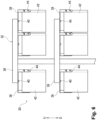
Figure 5A] Figure 5A is a diagram of a first irradiation stand seen from the opposite side (back side) of the irradiation side. - [
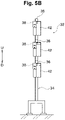
Figure 5B] Figure 5B is a diagram of the first irradiation stand seen from the right side ofFigure 5A . - [
Figure 6] Figure 6 is an enlarged view of a VI portion inFigure 5A . - [
Figure 7A] Figure 7A is a diagram of an illumination (a first illumination or a second illumination) attached with a bracket, which is seen from the irradiation side (front side). - [
Figure 7B] Figure 7B is a diagram of the illumination attached with the bracket, which is seen from the opposite side of the irradiation side. - [
Figure 8A] Figure 8A is a perspective view of the illumination attached with the bracket. - [
Figure 8B] Figure 8B is a perspective view of the illumination attached with the bracket and shows a state in which an adjustment jig is mounted to the illumination attached with the bracket. - [
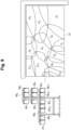
Figure 9] Figure 9 is a diagram illustrating irradiation ranges of the respective first illuminations. - [
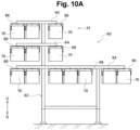
Figure 10A] Figure 10A is a diagram of a second irradiation stand seen from the opposite side (back side) of the irradiation side. - [
Figure 10B] Figure 10B is a diagram of the second irradiation stand seen from the left side ofFigure 10A . - [
Figure 11] Figure 11 is an enlarged view of an XI portion inFigure 10A . - [
Figure 12] Figure 12 is a diagram illustrating irradiation ranges of the respective second illuminations. - [
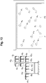
Figure 13] Figure 13 is a diagram illustrating positions on an adjustment sheet, which correspond to the irradiation ranges of the respective first illuminations. - [
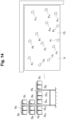
Figure 14] Figure 14 is a diagram illustrating positions on the adjustment sheet, which correspond to the irradiation ranges of the respective second illuminations. - [
Figure 15] Figure 15 is a perspective view of a bending system according to a second embodiment. - [
Figure 16] Figure 16 is a plan view of the bending system according to the second embodiment. - [
Figure 17] Figure 17 is a front view of the bending system according to the second embodiment. - Hereinafter, a first embodiment and a second embodiment will be described with reference to
Figures 1 to 17 . - Note that in the description and the scope of claims of the present application, "provided" is meant to include not only directly provided but also indirectly provided via another member. "Erected" means being set up in an upright state. The "lateral direction" is one of the horizontal directions and is synonymous with a direction parallel to the width direction of the press brake. The "front-back direction" is a horizontal direction orthogonal to the lateral direction, and is synonymous with a direction parallel to the depth direction of the press brake. "Holding" is meant to include sucking and gripping. In the drawings, "FF" indicates a forward direction, "FR" indicates a backward direction, "L" indicates a left direction, "R" indicates a right direction, "U" indicates an upper direction, and "D" indicates a downward direction.
- As shown in
Figures 1 to 3 , abending system 10 according to the first embodiment is a processing system that automatically bends a plate-shaped workpiece (sheet metal) W. The bendingsystem 10 includes apress brake 12 that bends the workpiece W through cooperation between a punch tool (not shown) and a die tool (not shown). - A predetermined setting area (carrying-in area) SA for a
pallet 14 to be set is formed in front of thepress brake 12. Thepallet 14 supports the workpiece W. In other words, in front of thepress brake 12, the carrying-in area SA for carrying in the workpiece W into thebending system 10 via thepallet 14 is formed. Thepallet 14 is set in the predetermined setting area SA by a fork lifter (not shown) or a hand lifter (not shown). Note that on the right side of the predetermined setting area, a carrying-out area TA for carrying out a bent product from the bendingsystem 10 via a product pallet (not shown) is formed. - As shown in
Figures 1 and4 , a plurality ofpedestals 16 that support thepallet 14 are provided on a floor surface of the predetermined setting area SA via a plurality oflow head bolts 18 and a plurality of anchors (not shown). A plurality of half-split shims (not shown) for adjusting a height location of each of thepedestals 16 are interposed between each of thepedestals 16 and the floor surface. Therefore, by adjusting the height location of each of thepedestals 16, it is possible to sufficiently ensure flatness of an upper surface of thepallet 14 set in the predetermined setting area SA. - As shown in
Figures 1 to 3 , aguide frame 20 extending in the lateral direction is provided between thepress brake 12 and the predetermined setting area SA. A bendingrobot 22, which assists in bending the workpiece W, is provided to theguide frame 20 in such a manner as to be movable in the lateral direction. In other words, the bendingrobot 22 is provided between thepress brake 12 and the predetermined setting area SA in such a manner as to be movable via theguide frame 20 in the lateral direction. The bendingrobot 22 has a known configuration shown in Patent Literature 2, for example, and includes an articulatedrobot arm 24. The bendingrobot 22 includes arobot hand 26 that is provided at the distal end of therobot arm 24 in an installable and removeable manner. Therobot hand 26 sucks the workpiece W on thepallet 14 set in the predetermined setting area SA. Note that as shown in Patent Literatures 3 and 4, therobot hand 26 may include a gripper (not shown) that grips the end portion of the workpiece W. - An L-shaped
support column 28 is erected on the floor surface on a left front side of the predetermined setting area SA, and thesupport column 28 includes a vertical portion (a perpendicular portion) 28a and ahorizontal portion 28b that is provided above thevertical portion 28a. At the distal end of thehorizontal portion 28b of thesupport column 28, amonocular camera 30 is provided as an image pickup unit that picks up, from an oblique upper direction, an image of the workpiece W on thepallet 14 set in the predetermined setting area SA. In other words, thecamera 30 is provided above and anterior to the predetermined setting area SA via thesupport column 28. Thecamera 30 includes a CCD (Charge Coupled Device) or a CMOS (Complementary Metal Oxide Semiconductor) as an image pickup element. Note that a stereo camera (not shown) may be used in lieu of themonocular camera 30. - As shown in
Figures 1 to 3 , afirst illumination stand 32, as a first illumination unit that irradiates an image pickup area of thecamera 30 with an illumination beam, is erected on the left front side of the predetermined setting area SA. Thefirst illumination stand 32 is arranged to be inclined with respect to the lateral direction so that a right end side thereof is located more forward than a left end side thereof. Then, the specific contents of the respective constituent members of thefirst illumination stand 32 are as follows. - As shown in
Figures 1 ,3 ,5A ,5B , and6 , afirst support frame 34 is erected on the left front side of the predetermined setting area SA. Thefirst support frame 34 includes a plurality of (three in the present embodiment)first beam members 36 that extend in the horizontal direction. Each of thefirst beam members 36 is provided with an inverted U-shapedfirst bracket 38 via a mountingbolt 40. Thefirst bracket 38 is rotatable around an axial center of the mountingbolt 40 that is a vertical axial center. - A
first illumination 42 for irradiation of the illumination beam in a right obliquely downward direction is provided to each of thefirst brackets 38 via a mountingbolt 44. In other words, thefirst illumination stand 32 includes a plurality of (13 in the present embodiment)first illuminations 42. The illumination beams from the plurality offirst illuminations 42 cast shadows on the right and rear edge portions (contour portions) of the workpiece W on thepallet 14 set in the predetermined setting area SA to clarify those edge portions. - As shown in
Figures 6 to 9 , each of thefirst illuminations 42 is rotatable around the axial center of the mountingbolt 44 that is a horizontal axial center. Each of thefirst illuminations 42 is rotatable around the axial center of the mountingbolt 40 integrally with thefirst bracket 38. A circular arc slit 38s is formed on each side surface of each of thefirst brackets 38. Amovable bolt 46 as a movable element is provided on each side surface of each of thefirst illuminations 42, and each of themovable bolts 46 moves in a state of being guided to theslit 38s of each of thefirst brackets 38. Further, each of thefirst illuminations 42 includes a rectangular box-shaped illuminationmain body 48 provided to each of thefirst brackets 38 and whose front side (irradiation side) is open, anacrylic panel 50 provided on the front side of the illuminationmain body 48, and a plurality of light emitting diodes (LEDs) 52 provided in the illuminationmain body 48. - As described above, each of the
first illuminations 42 is configured to be rotatable around the two orthogonal axial centers. In other words, the irradiation direction of each of thefirst illuminations 42 is configured to be adjustable so that an entire area on thepallet 14 is irradiated with the illumination beams from the plurality of first illuminations 42 (seeFigure 9 ). The two orthogonal axial centers refer to a horizontal axial center and a vertical axial center. InFigure 9 , each of thefirst illuminations 42 is attached with a numerical subscript for identification (421 to 4213). An irradiation range C of each of thefirst illuminations 42 is attached with a numerical subscript for identification (C1 to C13). Further, when the irradiation direction of each of thefirst illuminations 42 is adjusted, anadjustment jig 54 is used. Theadjustment jig 54 includes a jigmain body 56 that can be magnetically attached to an appropriate location of each of the illuminationmain bodies 48, and alaser pointer 58 that is provided to the jigmain body 56 and emits a visible beam. - As shown in
Figures 1 to 3 , asecond illumination stand 60, as a second illumination unit that irradiates the image pickup area of thecamera 30 with the illumination beam, is erected on the right front side of the predetermined setting area SA. Thesecond illumination stand 60 is arranged to be inclined with respect to the lateral direction so that a left end side thereof is located more forward than a right end side thereof. Thesecond illumination stand 60 is separated from thefirst illumination stand 32 in the lateral direction, and a taking-in and out passage EG for taking in and out thepallet 14 with respect to the predetermined setting area SA is formed between thefirst illumination stand 32 and thesecond illumination stand 60. Then, the specific contents of the respective constituent members of thesecond illumination stand 60 are as follows. - As shown in
Figures 1 ,3 ,10A ,10B , and11 , asecond support frame 62 is erected on the right front side of the predetermined setting area SA. Thesecond support frame 62 includes a plurality of (three in the present embodiment)second beam members 64 that extend in the horizontal direction. Each of thesecond beam members 64 is provided with an inverted U-shapedsecond bracket 66 via a mountingbolt 68. Thesecond bracket 66 is rotatable around the axial center of the mountingbolt 68 that is a vertical axial center. - A
second illumination 70 for irradiation of the illumination beam in a left obliquely downward direction is provided to each of thesecond brackets 66 via a mountingbolt 72. In other words, thesecond illumination stand 60 includes a plurality of (13 in the present embodiment)second illuminations 70. The plurality ofsecond illuminations 70 cast shadows on the left and rear edge portions (contour portions) of the workpiece W on thepallet 14 set in the predetermined setting area SA to clarify those edge portions. - As shown in
Figures 7A, 7B ,8A, 8B , and10A to 12 , each of thesecond illuminations 70 is rotatable around the axial center of the mountingbolt 72 that is a horizontal axial center. Each of thesecond illuminations 70 is rotatable around the axial center of the mountingbolt 68 integrally with thesecond bracket 66. A circular arc slit 66s is formed on each side surface of each of thesecond brackets 66. Amovable bolt 74 as a movable element is provided on each side surface of each of thesecond illuminations 70, and each of themovable bolts 74 moves in a state of being guided to theslit 66s of each of thesecond brackets 66. Further, each of thesecond illuminations 70 includes a rectangular box-shaped illuminationmain body 76 provided to each of thesecond brackets 66 and whose front side (irradiation side) is open, anacrylic panel 78 provided on the front side of the illuminationmain body 76, and a plurality of light emitting diodes (LEDs) 80 provided in the illuminationmain body 76. - As described above, each of the
second illuminations 70 is configured to be rotatable around the two orthogonal axial centers. In other words, the irradiation direction of each of thesecond illuminations 70 is configured to be adjustable so that the entire area on thepallet 14 set in the predetermined setting area SA is irradiated with the illumination beams from the plurality of second illuminations 70 (SeeFigure 12 ). InFigure 12 , each of thesecond illuminations 70 is attached with a numerical subscript for identification (701 to 7013). The irradiation range C of each of thesecond illuminations 70 is attached with a numerical subscript for identification (C1 to C13). Further, when the irradiation direction of each of thesecond illuminations 70 is adjusted, theadjustment jig 54 is used as described above. The jigmain body 56 of theadjustment jig 54 can be magnetically attached to an appropriate location of each of the illuminationmain bodies 76. - As shown in
Figures 1 to 3 , afirst guard 82 that protects thefirst illumination stand 32 is provided in the vicinity of the right side of thefirst illumination stand 32. Thefirst guard 82 is arranged to be along thefirst illumination stand 32. Asecond guard 84 that protects thesecond illumination stand 60 is provided in the vicinity of the left side of thesecond illumination stand 60. Thesecond guard 84 is arranged to be along thesecond illumination stand 60. Further, asafety fence 86 for ensuring the safety of the bending is provided around most of thebending system 10. Thesafety fence 86 includes a plurality of doors (not shown) for allowing the fork lifter or the hand lifter to pass through. - Although not shown, the bending
system 10 includes a numerical control device (a main control device) that controls thepress brake 12, and a robot control device that controls the bendingrobot 22. The bendingsystem 10 includes an illumination control device that controls thefirst illumination stand 32 and thesecond illumination stand 60, and an image processing device that performs image processing to a picked-up image of thecamera 30. The illumination control device separately executes an irradiation operation of the illumination beams from the plurality offirst illuminations 42 and an irradiation operation of the illumination beams from the plurality ofsecond illuminations 70. The image processing device corrects a distortion of the picked-up image of thecamera 30, which is caused by the inclination of the image pickup direction of thecamera 30 with respect to the vertical direction. The image processing device detects the location of the workpiece W on thepallet 14 based on the corrected picked-up image of thecamera 30. The robot control device controls the bendingrobot 22 so that therobot hand 26 holds a predetermined portion of the workpiece W based on the detected location of the workpiece W. Therefore, even if the workpiece W is not placed accurately at a predetermined position on thepallet 14, it is possible to sufficiently ensure the processing accuracy of the bending by appropriately operating the bendingrobot 22. - Next, a method for using the bending system according to the first embodiment will be described.
- As shown in
Figures 9 and13 , in a state in which the entire area of thepallet 14 is covered with a white adjustment sheet FS, the irradiation direction of each of thefirst illuminations 42 is adjusted such that a position P on the adjustment sheet FS, which corresponds to the irradiation range C of each of thefirst illuminations 42, is irradiated with the visible beam from the laser pointer 58 (seeFigure 8B ) of theadjustment jig 54 mounted to each of thefirst illuminations 42. Thereby, the illumination beams of thefirst illumination stand 32 can be adjusted. InFigure 13 , each of thefirst illuminations 42 is attached with a numerical subscript for identification (421 to 4213). The position P corresponding to the irradiation range C (C1 to C13) of each of the first illuminations 42 (421 to 4213) is attached with a numerical subscript for identification (P1 to P13). - Further, as shown in
Figures 12 and14 , in the state in which the entire area on thepallet 14 is covered with the adjustment sheet FS, the irradiation direction of each of thesecond illuminations 70 is adjusted such that the position P on the adjustment sheet FS, which corresponds to the irradiation range C of each of thesecond illuminations 70, is irradiated with the visible beam from the laser pointer 58 (seeFigure 8B ) of theadjustment jig 54 mounted to each of thesecond illuminations 70. Thereby, the illumination beams of thesecond illumination stand 60 can be adjusted. InFigure 14 , each of thesecond illuminations 70 is attached with a numerical subscript for identification (701 to 7013). The position P corresponding to the irradiation range C (C1 to C13) of each of the second illuminations 70 (701 to 7013) is attached with a numerical subscript for identification (P1 to P13). - As shown in
Figures 1 to 3 , when thecamera 30 picks up an image of the workpiece W on thepallet 14 from the oblique upper direction, an illumination operation of thefirst illumination stand 32 is executed so that the entire area on thepallet 14 is irradiated with the illumination beams from the plurality offirst illuminations 42. Then, shadows can be casted on the right and rear edge portions of the workpiece W on thepallet 14 to clarify those edge portions. Since the illumination beams from the plurality offirst illuminations 42 are directed in the right obliquely downward direction, the end surfaces of the left and front edge portions of the workpiece W on thepallet 14 can be recognized by thecamera 30. Therefore, it is not necessary to cast shadows on those edge portions. Further, an illumination operation of thesecond illumination stand 60 is executed so that the entire area on thepallet 14 is irradiated with the illumination beams from the plurality ofsecond illuminations 70. Then, shadows can be casted on the left and rear edge portions of the workpiece W on thepallet 14 to clarify those edge portions. Since the illumination beams from the plurality ofsecond illuminations 70 are directed in the left obliquely downward direction, the end surfaces of the right and front edge portions of the workpiece W on thepallet 14 can be recognized by thecamera 30. Therefore, it is not necessary to cast shadows on these edges. The execution timings of the illumination operation of thefirst illumination stand 32 and the illumination operation of thesecond illumination stand 60 are staggered. By clarifying the right, left, and rear edge portions of the workpiece W on thepallet 14, the image processing device can easily detect the location of the workpiece W by pattern matching. - Next, the operation and effect of the first embodiment will be described.
- As described above, since the
camera 30 is located above and anterior to the predetermined setting area SA, thecamera 30 can be sufficiently separated from the predetermined setting area SA. Since thefirst illumination stand 32 is located on the left front side of the predetermined setting area SA and thesecond illumination stand 60 is located on the right front side of the predetermined setting area SA, thefirst illumination stand 32 and thesecond illumination stand 60 can be sufficiently separated from the predetermined setting area SA. Therefore, the workpiece W sucked by a part of the bendingrobot 22 or therobot hand 26 does not interfere with thecamera 30, thefirst illumination stand 32, and thesecond illumination stand 60. In other words, the operating range of the bendingrobot 22 that sucks the workpiece W is not limited by thecamera 30 or the like. Therefore, according to the first embodiment, it is possible to increase the degree of freedom of the bending of thebending system 10 while sufficiently ensuring the processing accuracy of the bending. - As described above, the
first illumination stand 32 is arranged to be inclined with respect to the lateral direction so that the right end side thereof is located more forward than the left end side thereof. Thesecond illumination stand 60 is arranged to be inclined with respect to the lateral direction so that the left end side thereof is located more forward than the right end side thereof. A taking-in and out passage EG is formed between thefirst illumination stand 32 and thesecond illumination stand 60. Therefore, it is possible to sufficiently ensure a worker flow line in the vicinity of the predetermined setting area SA while allowing thepallet 14 to be taken in and out with respect to the predetermined setting area SA. Therefore, according to the first embodiment, the workability and operability of thebending system 10 can be improved. - As described above, the
first guard 82 is provided in the vicinity of the right side of thefirst illumination stand 32, and thesecond guard 84 is provided in the vicinity of the left side of thesecond illumination stand 60. Therefore, according to the first embodiment, damage to thefirst illumination stand 32 or thesecond illumination stand 60 due to contact with the fork lifter or the hand lifter can be sufficiently prevented. - As shown in
Figures 15 to 17 , abending system 88 according to a second embodiment automatically bends the workpiece W in the same manner as thebending system 10 of the first embodiment (seeFigure 1 ). The bendingsystem 88 has the same configurations as thebending system 10 except for a part, and of the configurations of thebending system 88, a configuration and the like different from those of thebending system 10 will be described. Note that of a plurality of constituent members of thebending system 88, those corresponding to the constituent members of thebending system 10 are denoted by the same reference numerals in the drawings. - The
first illumination stand 32 that irradiates the image pickup area of thecamera 30 with the illumination beam is erected on the left front side of the predetermined setting area SA. Thefirst illumination stand 32 is arranged in parallel along the lateral direction. Asecond illumination stand 60 that irradiates the image pickup area of thecamera 30 with the illumination beam is erected on the right front side of the predetermined setting area SA. Thesecond illumination stand 60 is arranged in parallel along the lateral direction. Note that thefirst illumination stand 32 and thesecond illumination stand 60 may each has a caster attached with a brake (not shown). A first guard (not shown) that protects thefirst illumination stand 32 may be provided in the vicinity of thefirst illumination stand 32. A second guard (not shown) that protects thesecond illumination stand 60 may be provided in the vicinity of thesecond illumination stand 60. - Next, the operation and effect of the second embodiment will be described.
- In the same manner as the operation of the first embodiment, the
first illumination stand 32 and thesecond illumination stand 60 can be sufficiently separated from the predetermined setting area SA. Therefore, the workpiece W sucked by the part of the bendingrobot 22 or therobot hand 26 does not interfere with thecamera 30, thefirst illumination stand 32, and thesecond illumination stand 60. In other words, the operating range of the bendingrobot 22 that sucks the workpiece W is not limited by thecamera 30 or the like. Therefore, according to the second embodiment, it is possible to increase the degree of freedom of the bending of thebending system 88 while sufficiently ensuring the processing accuracy of the bending. - It should be noted that the present invention is not limited to the descriptions of several embodiments described above, and can be implemented in various other aspects by making appropriate changes. Then, the scope of rights included in the present invention is not limited to the embodiments described above.
- The entire contents of
Japanese Patent Application No. 2020-089699 (Filing date: May 22, 2020
Claims (9)
- A bending system, comprising:a bending robot provided between a press brake and a predetermined setting area arranged in front of the press brake, including a robot hand for holding a workpiece on a pallet set in the predetermined setting area, and configured to assist in bending the workpiece;an image pickup unit provided above and anterior to the predetermined setting area and configured to pick up an image of the workpiece on the pallet from an oblique upper direction;a first illumination unit erected on a left front side of the predetermined setting area and configured to irradiate an image pickup area of the image pickup unit with an illumination beam; anda second illumination unit erected on a right front side of the predetermined setting area and configured to irradiate the image pickup area of the image pickup unit with the illumination beam.
- The bending system according to claim 1, whereinthe first illumination unit includes a plurality of first illuminations for irradiation of illumination beams in a right obliquely downward direction, and is configured such that an irradiation direction of each of the first illuminations is adjustable so that an entire area on the pallet is irradiated with the illumination beams from the plurality of first illuminations, andthe second illumination unit includes a plurality of second illuminations for irradiation of illumination beams in a left obliquely downward direction, and is configured such that an irradiation direction of each of the second illuminations is adjustable so that the entire area on the pallet is irradiated with the illumination beams from the plurality of second illuminations.
- The bending system according to claim 2, whereinthe first illumination unit includes a first support frame erected on a left front side of the predetermined setting area, and a plurality of first brackets provided rotatably around an axial center vertical to the first support frame, each of the first illuminations being provided rotatably around an axial center horizontal to each of the first brackets, andthe second illumination unit includes a second support frame erected on a right front side of the predetermined setting area, and a plurality of second brackets provided rotatably around an axial center vertical to the second support frame, each of the second illuminations being provided rotatably around an axial center horizontal to each of the second brackets.
- The bending system according to any one of claims 1 to 3, whereinthe first illumination unit is arranged to be inclined with respect to a lateral direction so that a right end side thereof is located more forward than a left end side thereof, andthe second illumination unit is arranged to be inclined with respect to the lateral direction so that a left end side thereof is located more forward than a right end side thereof.
- The bending system according to any one of claims 1 to 3, wherein the first illumination unit and the second illumination unit are each arranged in parallel along the lateral direction.
- The bending system according to any one of claims 1 to 5, further comprisinga first guard provided in a vicinity of the first illumination unit and configured to protect the first illumination unit, anda second guard provided in a vicinity of the second illumination unit and configured to protect the second illumination unit.
- A method for using the bending system according to claim 2, comprising, in a state in which an entire area of the pallet is covered with an adjustment sheet, adjusting an irradiation direction of each of the first illuminations such that a position on the adjustment sheet is irradiated with a visible beam from a laser pointer of an adjustment jig mounted to each of the first illuminations, the position on the adjustment sheet corresponding to an irradiation range of a respective one of the first illuminations, and adjusting an irradiation direction of each of the second illuminations such that a position on the adjustment sheet is irradiated with the visible beam from the laser pointer of the adjustment jig mounted to each of the second illuminations, the position on the adjustment sheet corresponding to an irradiation range of a respective one of the second illuminations.
- A method for using the bending system according to claim 2, comprising, when the image pickup unit picks up an image of the workpiece on the pallet from the oblique upper direction, executing an illumination operation of the first illumination unit so that the entire area on the pallet is irradiated with the illumination beams from the plurality of first illuminations, and executing an illumination operation of the second illumination unit so that the entire area on the pallet is irradiated with the illumination beams from the plurality of second illuminations.
- The method for using the bending system, according to claim 8, further comprising staggering execution timings of the illumination operation of the first illumination unit and the illumination operation of the second illumination unit.
Applications Claiming Priority (2)
| Application Number | Priority Date | Filing Date | Title |
|---|---|---|---|
| JP2020089699A JP7561519B2 (en) | 2020-05-22 | 2020-05-22 | Bending system and method of using same |
| PCT/JP2021/018424 WO2021235350A1 (en) | 2020-05-22 | 2021-05-14 | Bending system and method for using same |
Publications (3)
| Publication Number | Publication Date |
|---|---|
| EP4155003A1 true EP4155003A1 (en) | 2023-03-29 |
| EP4155003A4 EP4155003A4 (en) | 2023-11-08 |
| EP4155003B1 EP4155003B1 (en) | 2024-10-02 |
Family
ID=78708348
Family Applications (1)
| Application Number | Title | Priority Date | Filing Date |
|---|---|---|---|
| EP21808123.0A Active EP4155003B1 (en) | 2020-05-22 | 2021-05-14 | Bending system and method for using the same |
Country Status (5)
| Country | Link |
|---|---|
| US (1) | US12025299B2 (en) |
| EP (1) | EP4155003B1 (en) |
| JP (1) | JP7561519B2 (en) |
| CN (1) | CN115666807B (en) |
| WO (1) | WO2021235350A1 (en) |
Families Citing this family (3)
| Publication number | Priority date | Publication date | Assignee | Title |
|---|---|---|---|---|
| JP7248078B2 (en) * | 2017-03-30 | 2023-03-29 | 株式会社三洋物産 | game machine |
| JP7248079B2 (en) * | 2017-03-30 | 2023-03-29 | 株式会社三洋物産 | game machine |
| KR20250071326A (en) | 2023-11-14 | 2025-05-22 | 한국철도기술연구원 | Trolley system for non-destructive inspection of internal rail defects, and non-destructive inspection of internal rail defects method therewith |
Family Cites Families (28)
| Publication number | Priority date | Publication date | Assignee | Title |
|---|---|---|---|---|
| US5800048A (en) * | 1996-03-14 | 1998-09-01 | Musco Corporation | Split reflector lighting fixture |
| JPH10106309A (en) * | 1996-09-30 | 1998-04-24 | Iwasaki Electric Co Ltd | Emitter angle setting mechanism |
| JP3596434B2 (en) | 2000-06-30 | 2004-12-02 | 株式会社ダイフク | Article position recognition device |
| AT502501B1 (en) * | 2004-03-05 | 2007-04-15 | Trumpf Maschinen Austria Gmbh | BY LIGHT UNIT |
| JP2006107921A (en) | 2004-10-05 | 2006-04-20 | Pc Lights Inc | Lighting device |
| JP4020144B2 (en) * | 2006-03-10 | 2007-12-12 | オムロン株式会社 | Inspection method of surface condition |
| TWI335398B (en) * | 2007-08-30 | 2011-01-01 | Chieh Ouyang | Led lighting method and device |
| JP2009117315A (en) | 2007-11-09 | 2009-05-28 | Panasonic Electric Works Co Ltd | LED lighting device |
| JP5877639B2 (en) * | 2010-12-27 | 2016-03-08 | 富士機械製造株式会社 | Image generating apparatus and image generating method |
| JP2013101793A (en) | 2011-11-08 | 2013-05-23 | Chudenko Corp | Control method of road surface luminance by accuracy improvement of lighting fixture installation angle in tunnel using laser pointer |
| CN105090828B (en) * | 2013-02-25 | 2017-03-15 | 黄�俊 | Adjustable Projecting Lamp |
| JP5776716B2 (en) * | 2013-03-15 | 2015-09-09 | 株式会社安川電機 | Robot system and workpiece manufacturing method |
| JP6204723B2 (en) | 2013-07-05 | 2017-09-27 | 株式会社アマダホールディングス | Work support device and work gripping method |
| JP6394893B2 (en) | 2014-12-18 | 2018-09-26 | 三菱自動車工業株式会社 | Hydraulic clutch master cylinder mounting structure |
| JP2016135512A (en) | 2015-01-23 | 2016-07-28 | 東レエンジニアリング株式会社 | Plate-like object transfer device and plate-like object transfer method |
| JP6622598B2 (en) | 2016-01-14 | 2019-12-18 | 株式会社アマダホールディングス | Robot hand, articulated robot, and material loading method |
| JP2018120388A (en) | 2017-01-25 | 2018-08-02 | 株式会社アマダホールディングス | Work detection apparatus and method |
| JP6803254B2 (en) | 2017-02-08 | 2020-12-23 | 株式会社アマダ | Optical sensor installation structure and work loading system |
| JP6549644B2 (en) * | 2017-06-27 | 2019-07-24 | ファナック株式会社 | Machine learning apparatus, robot control system and machine learning method |
| JP6877272B2 (en) | 2017-07-10 | 2021-05-26 | 株式会社アマダ | Robot hand and bending robot |
| EP3438525B1 (en) * | 2017-08-04 | 2020-01-08 | Atlas Material Testing Technology GmbH | Lighting device for simulation apparatus for motor vehicle accidents |
| CN107617836A (en) | 2017-09-21 | 2018-01-23 | 重庆工商职业学院 | A kind of Intelligent welding industrial robot |
| JP2020089699A (en) | 2018-12-03 | 2020-06-11 | 合同会社ウルトラカンパニー | Filter attachable holder |
| JP6784361B1 (en) * | 2019-06-12 | 2020-11-11 | 株式会社アマダ | Work detection device and work detection method |
| CN110523909B (en) * | 2019-07-10 | 2021-02-05 | 南京航空航天大学 | An automatic nail feeding system and method based on robot vision |
| CN110930799A (en) | 2019-08-29 | 2020-03-27 | 苏州风正帆智能科技有限公司 | Industrial robot teaching training platform |
| JP7269864B2 (en) * | 2019-10-21 | 2023-05-09 | 株式会社アマダ | Work photographed image processing device and work photographed image processing method |
| JP7495864B2 (en) * | 2020-10-28 | 2024-06-05 | 株式会社アマダ | Workpiece transport system and workpiece transport method |
-
2020
- 2020-05-22 JP JP2020089699A patent/JP7561519B2/en active Active
-
2021
- 2021-05-14 EP EP21808123.0A patent/EP4155003B1/en active Active
- 2021-05-14 CN CN202180036536.7A patent/CN115666807B/en active Active
- 2021-05-14 WO PCT/JP2021/018424 patent/WO2021235350A1/en not_active Ceased
- 2021-05-14 US US17/926,585 patent/US12025299B2/en active Active
Also Published As
| Publication number | Publication date |
|---|---|
| EP4155003B1 (en) | 2024-10-02 |
| US12025299B2 (en) | 2024-07-02 |
| WO2021235350A1 (en) | 2021-11-25 |
| JP2021183349A (en) | 2021-12-02 |
| CN115666807A (en) | 2023-01-31 |
| US20230184417A1 (en) | 2023-06-15 |
| JP7561519B2 (en) | 2024-10-04 |
| CN115666807B (en) | 2026-01-02 |
| EP4155003A4 (en) | 2023-11-08 |
Similar Documents
| Publication | Publication Date | Title |
|---|---|---|
| EP4155003B1 (en) | Bending system and method for using the same | |
| EP3460834B1 (en) | Transport vehicle and transport method | |
| US10427253B2 (en) | Machine tool having a workpiece support and method for loading and unloading a workpiece support of a machine tool | |
| US8074975B2 (en) | Mechanical arrangement for processing plate-like workpieces | |
| EP3328181B1 (en) | Component mounting machine and component mounting system | |
| JP7261957B2 (en) | ELECTRONIC DEVICE ASSEMBLY DEVICE AND ELECTRONIC DEVICE ASSEMBLY METHOD | |
| US20180126682A1 (en) | Deformation Device and Method for Operating a Deformation Device | |
| CN104245176A (en) | Board conveying equipment and board processing system using it | |
| JP6561896B2 (en) | Work picking device | |
| US11219936B2 (en) | Tools, machines, and methods for machining planar workpieces | |
| US20190344436A1 (en) | Transferring system and method of operating the same | |
| US10369607B2 (en) | Safety device of press brake and controlling method of press brake | |
| US12600000B2 (en) | Workpiece conveying wheeled platform and working system | |
| EP2177326A2 (en) | Method for aligning a workpiece to a robot | |
| JP2000061752A (en) | Plate processing method and plate processing machine | |
| US5607281A (en) | Transfer device in a press | |
| CN114577806A (en) | Wall panel installation robot and visual inspection method | |
| CN119260224B (en) | Automatic sorting method and sorting system for laser blanking | |
| EP3763453B1 (en) | Method of bending sheet material using a clamp structure | |
| CN110636928B (en) | Stacking device, workpiece processing device, and method for operating a stacking device | |
| WO2018100706A1 (en) | Operation machine | |
| JP7816352B2 (en) | Sheet work stacking device and method | |
| JP2007268622A (en) | Workpiece transfer method, workpiece transfer device, and workpiece transfer system | |
| JP7716117B2 (en) | robotic device | |
| JPH0794052B2 (en) | Back gauge abutment positioning device |
Legal Events
| Date | Code | Title | Description |
|---|---|---|---|
| STAA | Information on the status of an ep patent application or granted ep patent |
Free format text: STATUS: THE INTERNATIONAL PUBLICATION HAS BEEN MADE |
|
| PUAI | Public reference made under article 153(3) epc to a published international application that has entered the european phase |
Free format text: ORIGINAL CODE: 0009012 |
|
| STAA | Information on the status of an ep patent application or granted ep patent |
Free format text: STATUS: REQUEST FOR EXAMINATION WAS MADE |
|
| 17P | Request for examination filed |
Effective date: 20221114 |
|
| AK | Designated contracting states |
Kind code of ref document: A1 Designated state(s): AL AT BE BG CH CY CZ DE DK EE ES FI FR GB GR HR HU IE IS IT LI LT LU LV MC MK MT NL NO PL PT RO RS SE SI SK SM TR |
|
| DAV | Request for validation of the european patent (deleted) | ||
| DAX | Request for extension of the european patent (deleted) | ||
| A4 | Supplementary search report drawn up and despatched |
Effective date: 20231011 |
|
| RIC1 | Information provided on ipc code assigned before grant |
Ipc: F21S 6/00 20060101ALI20231005BHEP Ipc: F21V 21/30 20060101ALI20231005BHEP Ipc: F21V 21/26 20060101ALI20231005BHEP Ipc: B21D 5/02 20060101AFI20231005BHEP |
|
| GRAP | Despatch of communication of intention to grant a patent |
Free format text: ORIGINAL CODE: EPIDOSNIGR1 |
|
| STAA | Information on the status of an ep patent application or granted ep patent |
Free format text: STATUS: GRANT OF PATENT IS INTENDED |
|
| INTG | Intention to grant announced |
Effective date: 20240620 |
|
| RIN1 | Information on inventor provided before grant (corrected) |
Inventor name: TAKATSU, SATOSHI Inventor name: NISHIHATA, YUTO Inventor name: KOIZUMI, NORIHISA |
|
| GRAS | Grant fee paid |
Free format text: ORIGINAL CODE: EPIDOSNIGR3 |
|
| P01 | Opt-out of the competence of the unified patent court (upc) registered |
Free format text: CASE NUMBER: APP_43219/2024 Effective date: 20240724 |
|
| GRAA | (expected) grant |
Free format text: ORIGINAL CODE: 0009210 |
|
| STAA | Information on the status of an ep patent application or granted ep patent |
Free format text: STATUS: THE PATENT HAS BEEN GRANTED |
|
| AK | Designated contracting states |
Kind code of ref document: B1 Designated state(s): AL AT BE BG CH CY CZ DE DK EE ES FI FR GB GR HR HU IE IS IT LI LT LU LV MC MK MT NL NO PL PT RO RS SE SI SK SM TR |
|
| REG | Reference to a national code |
Ref country code: GB Ref legal event code: FG4D |
|
| REG | Reference to a national code |
Ref country code: CH Ref legal event code: EP |
|
| REG | Reference to a national code |
Ref country code: IE Ref legal event code: FG4D |
|
| REG | Reference to a national code |
Ref country code: DE Ref legal event code: R096 Ref document number: 602021019684 Country of ref document: DE |
|
| REG | Reference to a national code |
Ref country code: LT Ref legal event code: MG9D |
|
| REG | Reference to a national code |
Ref country code: NL Ref legal event code: MP Effective date: 20241002 |
|
| REG | Reference to a national code |
Ref country code: AT Ref legal event code: MK05 Ref document number: 1728106 Country of ref document: AT Kind code of ref document: T Effective date: 20241002 |
|
| PG25 | Lapsed in a contracting state [announced via postgrant information from national office to epo] |
Ref country code: NL Free format text: LAPSE BECAUSE OF FAILURE TO SUBMIT A TRANSLATION OF THE DESCRIPTION OR TO PAY THE FEE WITHIN THE PRESCRIBED TIME-LIMIT Effective date: 20241002 |
|
| PG25 | Lapsed in a contracting state [announced via postgrant information from national office to epo] |
Ref country code: NL Free format text: LAPSE BECAUSE OF FAILURE TO SUBMIT A TRANSLATION OF THE DESCRIPTION OR TO PAY THE FEE WITHIN THE PRESCRIBED TIME-LIMIT Effective date: 20241002 |
|
| PG25 | Lapsed in a contracting state [announced via postgrant information from national office to epo] |
Ref country code: HR Free format text: LAPSE BECAUSE OF FAILURE TO SUBMIT A TRANSLATION OF THE DESCRIPTION OR TO PAY THE FEE WITHIN THE PRESCRIBED TIME-LIMIT Effective date: 20241002 Ref country code: IS Free format text: LAPSE BECAUSE OF FAILURE TO SUBMIT A TRANSLATION OF THE DESCRIPTION OR TO PAY THE FEE WITHIN THE PRESCRIBED TIME-LIMIT Effective date: 20250202 Ref country code: PT Free format text: LAPSE BECAUSE OF FAILURE TO SUBMIT A TRANSLATION OF THE DESCRIPTION OR TO PAY THE FEE WITHIN THE PRESCRIBED TIME-LIMIT Effective date: 20250203 |
|
| PG25 | Lapsed in a contracting state [announced via postgrant information from national office to epo] |
Ref country code: FI Free format text: LAPSE BECAUSE OF FAILURE TO SUBMIT A TRANSLATION OF THE DESCRIPTION OR TO PAY THE FEE WITHIN THE PRESCRIBED TIME-LIMIT Effective date: 20241002 |
|
| PG25 | Lapsed in a contracting state [announced via postgrant information from national office to epo] |
Ref country code: BG Free format text: LAPSE BECAUSE OF FAILURE TO SUBMIT A TRANSLATION OF THE DESCRIPTION OR TO PAY THE FEE WITHIN THE PRESCRIBED TIME-LIMIT Effective date: 20241002 |
|
| PG25 | Lapsed in a contracting state [announced via postgrant information from national office to epo] |
Ref country code: ES Free format text: LAPSE BECAUSE OF FAILURE TO SUBMIT A TRANSLATION OF THE DESCRIPTION OR TO PAY THE FEE WITHIN THE PRESCRIBED TIME-LIMIT Effective date: 20241002 |
|
| PG25 | Lapsed in a contracting state [announced via postgrant information from national office to epo] |
Ref country code: NO Free format text: LAPSE BECAUSE OF FAILURE TO SUBMIT A TRANSLATION OF THE DESCRIPTION OR TO PAY THE FEE WITHIN THE PRESCRIBED TIME-LIMIT Effective date: 20250102 |
|
| PG25 | Lapsed in a contracting state [announced via postgrant information from national office to epo] |
Ref country code: GR Free format text: LAPSE BECAUSE OF FAILURE TO SUBMIT A TRANSLATION OF THE DESCRIPTION OR TO PAY THE FEE WITHIN THE PRESCRIBED TIME-LIMIT Effective date: 20250103 Ref country code: LV Free format text: LAPSE BECAUSE OF FAILURE TO SUBMIT A TRANSLATION OF THE DESCRIPTION OR TO PAY THE FEE WITHIN THE PRESCRIBED TIME-LIMIT Effective date: 20241002 Ref country code: AT Free format text: LAPSE BECAUSE OF FAILURE TO SUBMIT A TRANSLATION OF THE DESCRIPTION OR TO PAY THE FEE WITHIN THE PRESCRIBED TIME-LIMIT Effective date: 20241002 |
|
| PG25 | Lapsed in a contracting state [announced via postgrant information from national office to epo] |
Ref country code: PL Free format text: LAPSE BECAUSE OF FAILURE TO SUBMIT A TRANSLATION OF THE DESCRIPTION OR TO PAY THE FEE WITHIN THE PRESCRIBED TIME-LIMIT Effective date: 20241002 Ref country code: CZ Free format text: LAPSE BECAUSE OF FAILURE TO SUBMIT A TRANSLATION OF THE DESCRIPTION OR TO PAY THE FEE WITHIN THE PRESCRIBED TIME-LIMIT Effective date: 20241002 |
|
| PG25 | Lapsed in a contracting state [announced via postgrant information from national office to epo] |
Ref country code: RS Free format text: LAPSE BECAUSE OF FAILURE TO SUBMIT A TRANSLATION OF THE DESCRIPTION OR TO PAY THE FEE WITHIN THE PRESCRIBED TIME-LIMIT Effective date: 20250102 |
|
| PG25 | Lapsed in a contracting state [announced via postgrant information from national office to epo] |
Ref country code: SM Free format text: LAPSE BECAUSE OF FAILURE TO SUBMIT A TRANSLATION OF THE DESCRIPTION OR TO PAY THE FEE WITHIN THE PRESCRIBED TIME-LIMIT Effective date: 20241002 |
|
| REG | Reference to a national code |
Ref country code: DE Ref legal event code: R097 Ref document number: 602021019684 Country of ref document: DE |
|
| PGFP | Annual fee paid to national office [announced via postgrant information from national office to epo] |
Ref country code: DE Payment date: 20250521 Year of fee payment: 5 |
|
| PG25 | Lapsed in a contracting state [announced via postgrant information from national office to epo] |
Ref country code: DK Free format text: LAPSE BECAUSE OF FAILURE TO SUBMIT A TRANSLATION OF THE DESCRIPTION OR TO PAY THE FEE WITHIN THE PRESCRIBED TIME-LIMIT Effective date: 20241002 |
|
| PGFP | Annual fee paid to national office [announced via postgrant information from national office to epo] |
Ref country code: GB Payment date: 20250527 Year of fee payment: 5 |
|
| PGFP | Annual fee paid to national office [announced via postgrant information from national office to epo] |
Ref country code: IT Payment date: 20250527 Year of fee payment: 5 |
|
| PG25 | Lapsed in a contracting state [announced via postgrant information from national office to epo] |
Ref country code: EE Free format text: LAPSE BECAUSE OF FAILURE TO SUBMIT A TRANSLATION OF THE DESCRIPTION OR TO PAY THE FEE WITHIN THE PRESCRIBED TIME-LIMIT Effective date: 20241002 |
|
| PGFP | Annual fee paid to national office [announced via postgrant information from national office to epo] |
Ref country code: FR Payment date: 20250528 Year of fee payment: 5 |
|
| PG25 | Lapsed in a contracting state [announced via postgrant information from national office to epo] |
Ref country code: RO Free format text: LAPSE BECAUSE OF FAILURE TO SUBMIT A TRANSLATION OF THE DESCRIPTION OR TO PAY THE FEE WITHIN THE PRESCRIBED TIME-LIMIT Effective date: 20241002 |
|
| PG25 | Lapsed in a contracting state [announced via postgrant information from national office to epo] |
Ref country code: SK Free format text: LAPSE BECAUSE OF FAILURE TO SUBMIT A TRANSLATION OF THE DESCRIPTION OR TO PAY THE FEE WITHIN THE PRESCRIBED TIME-LIMIT Effective date: 20241002 |
|
| PLBE | No opposition filed within time limit |
Free format text: ORIGINAL CODE: 0009261 |
|
| STAA | Information on the status of an ep patent application or granted ep patent |
Free format text: STATUS: NO OPPOSITION FILED WITHIN TIME LIMIT |
|
| PG25 | Lapsed in a contracting state [announced via postgrant information from national office to epo] |
Ref country code: SE Free format text: LAPSE BECAUSE OF FAILURE TO SUBMIT A TRANSLATION OF THE DESCRIPTION OR TO PAY THE FEE WITHIN THE PRESCRIBED TIME-LIMIT Effective date: 20241002 |
|
| 26N | No opposition filed |
Effective date: 20250703 |
|
| REG | Reference to a national code |
Ref country code: CH Ref legal event code: H13 Free format text: ST27 STATUS EVENT CODE: U-0-0-H10-H13 (AS PROVIDED BY THE NATIONAL OFFICE) Effective date: 20251223 |
|
| PG25 | Lapsed in a contracting state [announced via postgrant information from national office to epo] |
Ref country code: LU Free format text: LAPSE BECAUSE OF NON-PAYMENT OF DUE FEES Effective date: 20250514 |
|
| PG25 | Lapsed in a contracting state [announced via postgrant information from national office to epo] |
Ref country code: CH Free format text: LAPSE BECAUSE OF NON-PAYMENT OF DUE FEES Effective date: 20250531 |
|
| REG | Reference to a national code |
Ref country code: BE Ref legal event code: MM Effective date: 20250531 |
|
| PG25 | Lapsed in a contracting state [announced via postgrant information from national office to epo] |
Ref country code: MC Free format text: LAPSE BECAUSE OF FAILURE TO SUBMIT A TRANSLATION OF THE DESCRIPTION OR TO PAY THE FEE WITHIN THE PRESCRIBED TIME-LIMIT Effective date: 20241002 |
|
| PG25 | Lapsed in a contracting state [announced via postgrant information from national office to epo] |
Ref country code: IE Free format text: LAPSE BECAUSE OF NON-PAYMENT OF DUE FEES Effective date: 20250514 |
|
| PG25 | Lapsed in a contracting state [announced via postgrant information from national office to epo] |
Ref country code: BE Free format text: LAPSE BECAUSE OF NON-PAYMENT OF DUE FEES Effective date: 20250531 |