EP4154444B1 - Cqi-tabellenauswahl in sidelink - Google Patents
Cqi-tabellenauswahl in sidelink Download PDFInfo
- Publication number
- EP4154444B1 EP4154444B1 EP21725317.8A EP21725317A EP4154444B1 EP 4154444 B1 EP4154444 B1 EP 4154444B1 EP 21725317 A EP21725317 A EP 21725317A EP 4154444 B1 EP4154444 B1 EP 4154444B1
- Authority
- EP
- European Patent Office
- Prior art keywords
- cqi
- control information
- sci
- stage
- csi report
- Prior art date
- Legal status (The legal status is an assumption and is not a legal conclusion. Google has not performed a legal analysis and makes no representation as to the accuracy of the status listed.)
- Active
Links
Images

Classifications
-
- H—ELECTRICITY
- H04—ELECTRIC COMMUNICATION TECHNIQUE
- H04L—TRANSMISSION OF DIGITAL INFORMATION, e.g. TELEGRAPHIC COMMUNICATION
- H04L1/00—Arrangements for detecting or preventing errors in the information received
- H04L1/0001—Systems modifying transmission characteristics according to link quality, e.g. power backoff
- H04L1/0015—Systems modifying transmission characteristics according to link quality, e.g. power backoff characterised by the adaptation strategy
- H04L1/0016—Systems modifying transmission characteristics according to link quality, e.g. power backoff characterised by the adaptation strategy involving special memory structures, e.g. look-up tables
-
- H—ELECTRICITY
- H04—ELECTRIC COMMUNICATION TECHNIQUE
- H04W—WIRELESS COMMUNICATION NETWORKS
- H04W72/00—Local resource management
- H04W72/20—Control channels or signalling for resource management
-
- H—ELECTRICITY
- H04—ELECTRIC COMMUNICATION TECHNIQUE
- H04L—TRANSMISSION OF DIGITAL INFORMATION, e.g. TELEGRAPHIC COMMUNICATION
- H04L1/00—Arrangements for detecting or preventing errors in the information received
- H04L1/0001—Systems modifying transmission characteristics according to link quality, e.g. power backoff
- H04L1/0023—Systems modifying transmission characteristics according to link quality, e.g. power backoff characterised by the signalling
- H04L1/0025—Transmission of mode-switching indication
-
- H—ELECTRICITY
- H04—ELECTRIC COMMUNICATION TECHNIQUE
- H04L—TRANSMISSION OF DIGITAL INFORMATION, e.g. TELEGRAPHIC COMMUNICATION
- H04L1/00—Arrangements for detecting or preventing errors in the information received
- H04L1/0001—Systems modifying transmission characteristics according to link quality, e.g. power backoff
- H04L1/0023—Systems modifying transmission characteristics according to link quality, e.g. power backoff characterised by the signalling
- H04L1/0026—Transmission of channel quality indication
-
- H—ELECTRICITY
- H04—ELECTRIC COMMUNICATION TECHNIQUE
- H04L—TRANSMISSION OF DIGITAL INFORMATION, e.g. TELEGRAPHIC COMMUNICATION
- H04L1/00—Arrangements for detecting or preventing errors in the information received
- H04L1/0001—Systems modifying transmission characteristics according to link quality, e.g. power backoff
- H04L1/0023—Systems modifying transmission characteristics according to link quality, e.g. power backoff characterised by the signalling
- H04L1/0032—Without explicit signalling
-
- H—ELECTRICITY
- H04—ELECTRIC COMMUNICATION TECHNIQUE
- H04L—TRANSMISSION OF DIGITAL INFORMATION, e.g. TELEGRAPHIC COMMUNICATION
- H04L5/00—Arrangements affording multiple use of the transmission path
- H04L5/003—Arrangements for allocating sub-channels of the transmission path
- H04L5/0053—Allocation of signalling, i.e. of overhead other than pilot signals
- H04L5/0057—Physical resource allocation for CQI
-
- H—ELECTRICITY
- H04—ELECTRIC COMMUNICATION TECHNIQUE
- H04W—WIRELESS COMMUNICATION NETWORKS
- H04W24/00—Supervisory, monitoring or testing arrangements
- H04W24/08—Testing, supervising or monitoring using real traffic
Definitions
- the present disclosure relates generally to communication systems, and more particularly, to wireless communication based on sidelink.
- Wireless communication systems are widely deployed to provide various telecommunication services such as telephony, video, data, messaging, and broadcasts.
- Typical wireless communication systems may employ multiple-access technologies capable of supporting communication with multiple users by sharing available system resources. Examples of such multiple-access technologies include code division multiple access (CDMA) systems, time division multiple access (TDMA) systems, frequency division multiple access (FDMA) systems, orthogonal frequency division multiple access (OFDMA) systems, single-carrier frequency division multiple access (SC-FDMA) systems, and time division synchronous code division multiple access (TD-SCDMA) systems.
- CDMA code division multiple access
- TDMA time division multiple access
- FDMA frequency division multiple access
- OFDMA orthogonal frequency division multiple access
- SC-FDMA single-carrier frequency division multiple access
- TD-SCDMA time division synchronous code division multiple access
- 5G New Radio is part of a continuous mobile broadband evolution promulgated by Third Generation Partnership Project (3GPP) to meet new requirements associated with latency, reliability, security, scalability (e.g., with Internet of Things (IoT)), and other requirements.
- 3GPP Third Generation Partnership Project
- 5G NR includes services associated with enhanced mobile broadband (eMBB), massive machine type communications (mMTC), and ultra-reliable low latency communications (URLLC).
- eMBB enhanced mobile broadband
- mMTC massive machine type communications
- URLLC ultra-reliable low latency communications
- Some aspects of 5G NR may be based on the 4G Long Term Evolution (LTE) standard.
- LTE Long Term Evolution
- aspects of wireless communication may comprise direct communication between devices based on sidelink, such as vehicle-to-everything (V2X) or other device-to-device (D2D) communication.
- V2X vehicle-to-everything
- D2D device-to-device
- Implementations may range a spectrum from chip-level or modular components to non-modular, non-chip-level implementations and further to aggregate, distributed, or original equipment manufacturer (OEM) devices or systems incorporating one or more aspects of the described innovations.
- devices incorporating described aspects and features may also include additional components and features for implementation and practice of claimed and described aspect.
- transmission and reception of wireless signals necessarily includes a number of components for analog and digital purposes (e.g., hardware components including antenna, RF-chains, power amplifiers, modulators, buffer, processor(s), interleaver, adders/summers, etc.).
- innovations described herein may be practiced in a wide variety of devices, chip-level components, systems, distributed arrangements, end-user devices, etc. of varying sizes, shapes, and constitution.
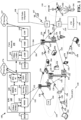
- FIG. 1 is a diagram illustrating an example of a wireless communications system and an access network 100.
- Some wireless communication may be exchanged directly between wireless devices, e.g., over sidelink or a PC5 interface.
- sidelink communication may include vehicle-based communication devices that can communicate from vehicle-to-vehicle (V2V), vehicle-to-infrastructure (V2I) (e.g., from the vehicle-based communication device to road infrastructure nodes such as a Road Side Unit (RSU)), vehicle-to-network (V2N) (e.g., from the vehicle-based communication device to one or more network nodes, such as a base station), vehicle-to-pedestrian (V2P), cellular vehicle-to-everything (C-V2X), and/or a combination thereof and/or with other devices, which can be collectively referred to as vehicle-to-anything (V2X) communications.
- V2V vehicle-to-vehicle
- V2I vehicle-to-infr
- a UE 104 e.g., a transmitting Vehicle User Equipment (VUE) or other UE, may be configured to transmit messages directly to another UE 104.
- the communication may be based on V2X or other D2D communication, such as Proximity Services (ProSe), etc.
- Communication based on V2X and/or D2D may also be transmitted and received by other transmitting and receiving devices, such as Road Side Unit (RSU) 107, etc.
- RSU Road Side Unit
- aspects of the communication may be based on PC5 or sidelink communication e.g., as described in connection with the example in FIG. 2 .
- the UE 104 may include a CQI table component 198 configured to receive a first set of control information, e.g., in a first portion of SCI indicating an MCS table and a second set of control information triggering a CSI report, e.g., in a second portion of SCI, and to determine a CQI table for the CSI report based on the MCS table indicated in the first set of control information.
- the UE 104 that transmits the SCI may include a CSI component 199 configured to transmit the first set of control information indicating an MCS table and the second set of control information triggering a CSI report from a receiver.
- the CSI component 199 may be configured to receive the CSI report in response to the second set of control information and based on the CQI table associated with the MCS table indicated in the first set of control information.
- the wireless communications system (also referred to as a wireless wide area network (WWAN)) includes base stations 102, UEs 104, an Evolved Packet Core (EPC) 160, and another core network 190 (e.g., a 5G Core (5GC)).
- the base stations 102 may include macrocells (high power cellular base station) and/or small cells (low power cellular base station).
- the macrocells include base stations.
- the small cells include femtocells, picocells, and microcells.
- the base stations 102 may perform one or more of the following functions: transfer of user data, radio channel ciphering and deciphering, integrity protection, header compression, mobility control functions (e.g., handover, dual connectivity), inter-cell interference coordination, connection setup and release, load balancing, distribution for non-access stratum (NAS) messages, NAS node selection, synchronization, radio access network (RAN) sharing, multimedia broadcast multicast service (MBMS), subscriber and equipment trace, RAN information management (RIM), paging, positioning, and delivery of warning messages.
- the base stations 102 may communicate directly or indirectly (e.g., through the EPC 160 or core network 190) with each other over third backhaul links 134 (e.g., X2 interface).
- the first backhaul links 132, the second backhaul links 184, and the third backhaul links 134 may be wired or wireless.
- the base stations 102 may wirelessly communicate with the UEs 104. Each of the base stations 102 may provide communication coverage for a respective geographic coverage area 110. There may be overlapping geographic coverage areas 110. For example, the small cell 102' may have a coverage area 110' that overlaps the coverage area 110 of one or more macro base stations 102.
- a network that includes both small cell and macrocells may be known as a heterogeneous network.
- a heterogeneous network may also include Home Evolved Node Bs (eNBs) (HeNBs), which may provide service to a restricted group known as a closed subscriber group (CSG).
- eNBs Home Evolved Node Bs
- CSG closed subscriber group
- the component carriers may include a primary component carrier and one or more secondary component carriers.
- a primary component carrier may be referred to as a primary cell (PCell) and a secondary component carrier may be referred to as a secondary cell (SCell).
- D2D communication link 158 may use the DL/UL WWAN spectrum.
- the D2D communication link 158 may use one or more sidelink channels, such as a physical sidelink broadcast channel (PSBCH), a physical sidelink discovery channel (PSDCH), a physical sidelink shared channel (PSSCH), and a physical sidelink control channel (PSCCH).
- sidelink channels such as a physical sidelink broadcast channel (PSBCH), a physical sidelink discovery channel (PSDCH), a physical sidelink shared channel (PSSCH), and a physical sidelink control channel (PSCCH).
- sidelink channels such as a physical sidelink broadcast channel (PSBCH), a physical sidelink discovery channel (PSDCH), a physical sidelink shared channel (PSSCH), and a physical sidelink control channel (PSCCH).
- sidelink channels such as a physical sidelink broadcast channel (PSBCH), a physical sidelink discovery channel (PSDCH), a physical sidelink shared channel (PSSCH), and a physical sidelink control channel (PSCCH).
- the small cell 102' may operate in a licensed and/or an unlicensed frequency spectrum. When operating in an unlicensed frequency spectrum, the small cell 102' may employ NR and use the same 5 GHz unlicensed frequency spectrum as used by the Wi-Fi AP 150. The small cell 102', employing NR in an unlicensed frequency spectrum, may boost coverage to and/or increase capacity of the access network.
- FR2 which is often referred to (interchangeably) as a "millimeter wave” band in documents and articles, despite being different from the extremely high frequency (EHF) band (30 GHz - 300 GHz) which is identified by the International Telecommunications Union (ITU) as a "millimeter wave” band.
- EHF extremely high frequency
- ITU International Telecommunications Union
- FR4a or FR4-1 52.6 GHz - 71 GHz
- FR4 52.6 GHz - 114.25 GHz
- FR5 114.25 GHz - 300 GHz.
- Each of these higher frequency bands falls within the EHF band.
- sub-6 GHz or the like if used herein may broadly represent frequencies that may be less than 6 GHz, may be within FR1, or may include mid-band frequencies.
- millimeter wave or the like if used herein may broadly represent frequencies that may include mid-band frequencies, may be within FR2, FR4, FR4-a or FR4-1, and/or FR5, or may be within the EHF band.
- a base station 102 may include and/or be referred to as an eNB, gNodeB (gNB), or another type of base station.
- Some base stations, such as gNB 180 may operate in a traditional sub 6 GHz spectrum, in millimeter wave (mmW) frequencies, and/or near mmW frequencies in communication with the UE 104.
- mmW millimeter wave
- mmW base station Extremely high frequency (EHF) is part of the RF in the electromagnetic spectrum.
- EHF Extremely high frequency
- the mmW base station 180 may utilize beamforming 182 with the UE 104 to compensate for the extremely high path loss and short range.
- the base station 180 and the UE 104 may each include a plurality of antennas, such as antenna elements, antenna panels, and/or antenna arrays to facilitate the beamforming.
- the base station 180 may transmit a beamformed signal to the UE 104 in one or more transmit directions 182'.
- the UE 104 may receive the beamformed signal from the base station 180 in one or more receive directions 182".
- the UE 104 may also transmit a beamformed signal to the base station 180 in one or more transmit directions.
- the base station 180 may receive the beamformed signal from the UE 104 in one or more receive directions.
- the base station 180 / UE 104 may perform beam training to determine the best receive and transmit directions for each of the base station 180 / UE 104.
- the transmit and receive directions for the base station 180 may or may not be the same.
- the transmit and receive directions for the UE 104 may or may not be the same.
- the PDN Gateway 172 provides UE IP address allocation as well as other functions.
- the PDN Gateway 172 and the BM-SC 170 are connected to the IP Services 176.
- the IP Services 176 may include the Internet, an intranet, an IP Multimedia Subsystem (IMS), a PS Streaming Service, and/or other IP services.
- the BM-SC 170 may provide functions for MBMS user service provisioning and delivery.
- the BM-SC 170 may serve as an entry point for content provider MBMS transmission, may be used to authorize and initiate MBMS Bearer Services within a public land mobile network (PLMN), and may be used to schedule MBMS transmissions.
- PLMN public land mobile network
- Examples of UEs 104 include a cellular phone, a smart phone, a session initiation protocol (SIP) phone, a laptop, a personal digital assistant (PDA), a satellite radio, a global positioning system, a multimedia device, a video device, a digital audio player (e.g., MP3 player), a camera, a game console, a tablet, a smart device, a wearable device, a vehicle, an electric meter, a gas pump, a large or small kitchen appliance, a healthcare device, an implant, a sensor/actuator, a display, or any other similar functioning device.
- SIP session initiation protocol
- PDA personal digital assistant
- the UEs 104 may be referred to as IoT devices (e.g., parking meter, gas pump, toaster, vehicles, heart monitor, etc.).
- the UE 104 may also be referred to as a station, a mobile station, a subscriber station, a mobile unit, a subscriber unit, a wireless unit, a remote unit, a mobile device, a wireless device, a wireless communications device, a remote device, a mobile subscriber station, an access terminal, a mobile terminal, a wireless terminal, a remote terminal, a handset, a user agent, a mobile client, a client, or some other suitable terminology.
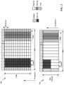
- Each subframe may include one or more time slots. Subframes may also include mini-slots, which may include 7, 4, or 2 symbols. Each slot may include 7 or 14 symbols, depending on the slot configuration. For slot configuration 0, each slot may include 14 symbols, and for slot configuration 1, each slot may include 7 symbols.
- Diagram 200 illustrates a single resource block of a single slot transmission, e.g., which may correspond to a 0.5 ms transmission time interval (TTI).
- a physical sidelink control channel may be configured to occupy multiple physical resource blocks (PRBs), e.g., 10, 12, 15, 20, or 25 PRBs.
- the PSCCH may be limited to a single sub-channel.
- a PSCCH duration may be configured to be 2 symbols or 3 symbols, for example.
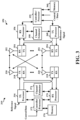
- FIG. 3 is a block diagram of a first wireless communication device 310 in communication with a second wireless communication device 350.
- the devices 310 and 350 may communicate based on sidelink using a PC5 interface.
- the devices 310 and the 350 may comprise a UE, an RSU, a base station, etc.
- Packets may be provided to a controller/processor 375 that implements layer 3 and layer 2 functionality.
- Layer 3 includes a radio resource control (RRC) layer
- layer 2 includes a packet data convergence protocol (PDCP) layer, a radio link control (RLC) layer, and a medium access control (MAC) layer.
- RRC radio resource control
- PDCP packet data convergence protocol
- RLC radio link control
- MAC medium access control
- each receiver 354RX receives a signal through its respective antenna 352.
- Each receiver 354RX recovers information modulated onto an RF carrier and provides the information to the receive (RX) processor 356.
- the TX processor 368 and the RX processor 356 implement layer 1 functionality associated with various signal processing functions.
- the RX processor 356 may perform spatial processing on the information to recover any spatial streams destined for the device 350. If multiple spatial streams are destined for the device 350, they may be combined by the RX processor 356 into a single OFDM symbol stream.
- the RX processor 356 then converts the OFDM symbol stream from the time-domain to the frequency domain using a Fast Fourier Transform (FFT).
- FFT Fast Fourier Transform
- the symbols on each subcarrier, and the reference signal, are recovered and demodulated by determining the most likely signal constellation points transmitted by device 310. These soft decisions may be based on channel estimates computed by the channel estimator 358. The soft decisions are then decoded and deinterleaved to recover the data and control signals that were originally transmitted by device 310 on the physical channel. The data and control signals are then provided to the controller/processor 359, which implements layer 3 and layer 2 functionality.
- the controller/processor 359 can be associated with a memory 360 that stores program codes and data.
- the memory 360 may be referred to as a computer-readable medium.
- the controller/processor 359 may provide demultiplexing between transport and logical channels, packet reassembly, deciphering, header decompression, and control signal processing.
- the controller/processor 359 is also responsible for error detection using an ACK and/or NACK protocol to support HARQ operations.
- the controller/processor 359 may provide RRC layer functionality associated with system information (e.g., MIB, SIBs) acquisition, RRC connections, and measurement reporting; PDCP layer functionality associated with header compression / decompression, and security (ciphering, deciphering, integrity protection, integrity verification); RLC layer functionality associated with the transfer of upper layer PDUs, error correction through ARQ, concatenation, segmentation, and reassembly of RLC SDUs, re-segmentation of RLC data PDUs, and reordering of RLC data PDUs; and MAC layer functionality associated with mapping between logical channels and transport channels, multiplexing of MAC SDUs onto TBs, demultiplexing of MAC SDUs from TBs, scheduling information reporting, error correction through HARQ, priority handling, and logical channel prioritization.
- RRC layer functionality associated with system information (e.g., MIB, SIBs) acquisition, RRC connections, and measurement reporting
- PDCP layer functionality associated with header
- Channel estimates derived by a channel estimator 358 from a reference signal or feedback transmitted by device 310 may be used by the TX processor 368 to select the appropriate coding and modulation schemes, and to facilitate spatial processing.
- the spatial streams generated by the TX processor 368 may be provided to different antenna 352 via separate transmitters 354TX. Each transmitter 354TX may modulate an RF carrier with a respective spatial stream for transmission.
- Each receiver 318RX receives a signal through its respective antenna 320.
- Each receiver 318RX recovers information modulated onto an RF carrier and provides the information to a RX processor 370.
- the controller/processor 375 can be associated with a memory 376 that stores program codes and data.
- the memory 376 may be referred to as a computer-readable medium.
- the controller/processor 375 provides demultiplexing between transport and logical channels, packet reassembly, deciphering, header decompression, control signal processing.
- the controller/processor 375 is also responsible for error detection using an ACK and/or NACK protocol to support HARQ operations.
- At least one of the TX processor 368, the RX processor 356, and the controller/processor 359 may be configured to perform aspects in connection with the CQI table component 198 of FIG. 1 .
- At least one of the TX processor 316, the RX processor 370, and the controller/processor 375 may be configured to perform aspects in connection with the CSI component 199 of FIG. 1 .
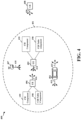
- FIG. 4 illustrates an example 400 of wireless communication between devices based on V2X or other D2D communication.
- the communication may be based on a slot structure comprising aspects described in connection with FIG. 2 .
- the UE 402 may transmit a sidelink transmission 414, e.g., comprising a control channel (e.g., PSCCH) and/or a corresponding data channel (e.g., PSSCH), that may be received by UEs 404, 406, 408.
- a control channel may include information (e.g., sidelink control information (SCI)) for decoding the data channel including reservation information, such as information about time and/or frequency resources that are reserved for the data channel transmission.
- SCI sidelink control information
- the SCI may indicate a number of TTIs, as well as the RBs that will be occupied by the data transmission.
- the SCI may also be used by receiving devices to avoid interference by refraining from transmitting on the reserved resources.
- the UEs 402, 404, 406, 408 may each be capable of sidelink transmission in addition to sidelink reception. Thus, UEs 404, 406, 408 are illustrated as transmitting sidelink transmissions 413, 415, 416, 420.
- the sidelink transmissions 413, 414, 415, 416, 420 may be unicast, broadcast or multicast to nearby devices.
- UE 404 may transmit communication 413, 415 intended for receipt by other UEs within a range 401 of UE 404, and UE 406 may transmit communication 416.
- RSU 407 may receive communication from and/or transmit communication 418 to UEs 402, 404, 406, 408.
- Sidelink communication may be based on different types or modes of resource allocation mechanisms.
- a first resource allocation mode (which may be referred to herein as "Mode 1")
- centralized resource allocation may be provided by a network entity.
- a base station 102 or 180 may determine resources for sidelink communication and may allocate resources to different UEs 104 to use for sidelink transmissions.
- a UE receives the allocation of sidelink resources from the base station 102 or 180.
- a second resource allocation mode (which may be referred to herein as "Mode 2”), distributed resource allocation may be provided. In Mode 2, each UE may autonomously determine resources to use for sidelink transmission.
- each UE may use a sensing technique to monitor for resource reservations by other sidelink UEs and may select resources for sidelink transmissions from unreserved resources.
- Devices communicating based on sidelink may determine one or more radio resources in the time and frequency domain that are used by other devices in order to select transmission resources that avoid collisions with other devices.
- the sidelink transmission and/or the resource reservation may be periodic or aperiodic, where a UE may reserve resources for transmission in a current slot and up to two future slots.
- the SCI-1 may include one or more of priority information (e.g., a quality of service QoS value), a PSSCH resource assignment (such as frequency and time resource assignment for PSSCH), a resource reservation period, a PSSCH DMRS pattern, a format information of SCI-2 (such as size information), an offset for SCI-2 control resource allocation, an indication of a number of PSSCH DMRS ports, a modulation and coding scheme (MCS), or the like.
- the SCI-2 may include one or more of a HARQ process ID, a new data indicator (NDI), a source ID, a destination ID, a CSI report trigger, a Zone ID of transmitter and/or a communication range.
- the UE 402, 404, 406, 408 or RSU 407 may comprise a CQI Table component 198 and/or a CSI component 199, as described in connection with FIG. 1 .
- the UEs may use the CSI component 199 when requesting/receiving CSI reports from other UEs and may use the CQI table component 198 when transmitting CSI reports to a requesting UE.
- the UEs may operate as a sidelink receiver and a sidelink transmitter, the UEs may include both components and may use the components based on whether the UE is transmitting sidelink communication or receiving sidelink communication.
- Wireless communication may be based on a modulation and coding scheme that provides a code rate for data transmitted by a wireless device.
- the MCS may be based on a table. There may be multiple MCS tables. For example, for communication between a base station and a UE over a Uu interface with cyclic prefix - orthogonal frequency division multiplexing (CP-OFDM), there may be three MCS tables.
- a first table may include a 64-QAM MCS table.
- a second table may include a 256-QAM table.
- a third table may include a low spectral efficiency MCS table. Multiple MCS tables may also be used in sidelink communication.
- a first CQI table includes a 64-QAM MCS table associated with a 10% block error rate (BLER) target.
- a second CQI table includes a 256 QAM table associated with a 10% BLER target.
- a third CQI table includes a low spectral efficiency CQI table associated with a 1e-5 BLER target.
- a base station configures the UE with a CQI table for each CSI report configuration. For example, the base station may configure the UE for a CSI report in downlink control information that indicates the CQI table for the configured CSI report.
- a CSI report configured by a base station in sidelink communication, there may be a single CSI report configuration for a unicast link between two UEs, e.g., between UE 402 and 406 in FIG. 4 .
- the MCS table for communication may be signaled from one UE to the other UE in a first stage SCI (e.g., SCI-1).
- Periodic CSI reporting may not be supported for sidelink.
- an aperiodic CSI report may be triggered based on SCI received from another UE.
- a second stage SCI e.g., SCI-2
- aspects presented herein enable a UE that is triggered to send an aperiodic CSI report over sidelink to determine a CQI table to use for the CSI report.
- the aspects may enable different CQI tables to be applied for different CSI reports even though there may be a single CSI report configuration for unicast communication between the two UEs.
- the UE that is triggered to send the CSI report may determine the CQI table for the CSI report based on an MCS table indication in SCI.
- the SCI may be associated with the triggered CSI report.
- the SCI may comprise the CSI report trigger.
- the MCS table indication may be received in a first set of control information (such as SCI-1), and the CSI trigger may be received in a second set of control information (such as SCI-2).
- the UE may use an association or relationship between the control information to determine the CQI table, for reporting CSI in the CSI report, based on the MCS of the associated control information.
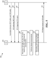
- FIG. 5 illustrates an example communication flow 500 between a UE 502 and a UE 504 that includes the transmission of an aperiodic CSI report over sidelink.
- the UE 504 sends SCI-1 505 indicating an MCS table to the UE 502.
- the UE 504 may have a unicast link with the UE 502.
- the UE 504 may broadcast or groupcast the SCI-1 to nearby UEs including the UE 502.
- the UE 504 then transmits the SCI-2 507 with an indication for the UE 502 to provide a CSI report.
- the SCI-2 may be referred to as triggering an aperiodic CSI report by the UE 502.
- the UE 502 In response to receiving the SCI-2 507, the UE 502 performs channel measurements, at 509, and calculates the CSI. For example, at 510, the UE may determine a CQI based on the channel measurements performed at 509 and the CQI table determined at 508. For example, the UE 502 may measure one or more of an achievable spectral efficiency (and indicated as a channel quality index (CQI), a rank of the channel (and indicated as a rank indicator (RI)), and a precoder that achieves the peak spectral efficiency (and indicated as a precoder matrix index (PMI)). The UE 502 reports the CSI, including the CQI, to the UE 504 in a CSI report 511.
- CQI channel quality index
- RI rank indicator
- PMI precoder matrix index
- the CSI report may include an indicator that carries information about the channel quality.
- the indicator may include an index from a CQI table.
- the CQI table may include entries based on modulation, code rate, and efficiency.
- the CQI table shown here provides one example MCS table to illustrate the concept.
- the UE may determine an index from the table that represents the measured channel quality and may include the index in the CSI report 511. The use of the index from the CQI table enables the UE to report a quantized value for the observed channel quality.
- the UE 502 determines the CQI table to use for the CSI report 511 based on the MCS table indicated in the SCI-1, e.g., the SCI-1 that is associated with the SCI-2 that triggered the CSI report.
- the UE 502 determines which of the CQI tables to use for the CSI report based on the MCS table indicated in the SCI-1.
- Each of the multiple MCS tables is associated with a particular CQI table.
- the association may be defined, in some examples.
- the association between an MCS table and a CQI table may be defined in a standard.
- the association may be configured, e.g., over PC5-RRC signaling.
- an association between the MCS tables and the CQI tables may be indicated in PC5-RRC signaling, at 503.
- a low spectral efficiency 64 QAM MCS table may be associated with a low spectral efficiency 64 QAM CQI table.
- a regular 64 QAM MCS table may be associated with a regular 64 QAM CQI table.
- a 256 QAM MCS table may be associated with a 256 QAM CQI table.
- Different SCI-1 from the UE 504 may indicate different MCS tables.
- the UE 502 uses the MCS table indicated in the SCI-1 to determine the CQI table for reporting CSI, the UE 502 uses different CQI tables for a CSI report triggered in SCI-2 that is associated with SCI-1 indicating different MCS tables.
- the BLER target may be based on the CQI table, e.g., the CQI table determined by the UE at 508.
- the aspects presented herein enable the CQI table to be determined by the UE 502 without signaling the CQI table to the UE 502, which improves the efficient use of wireless resources and reduced the amount of signaling between the two UEs. Additionally, the manner of determining the CQI table presented in FIG. 5 enables different CQI tables to be used for different CSI reports even if there is a single CSI configuration for the sidelink unicast between two UEs.
- the CQI table may be updated in RRC signaling.
- the aspects presented in FIG. 5 enable the CQI table to updated when the MCS table changes and without an RRC reconfiguration.
- FIG. 6 is a flowchart 600 of a method of wireless communication.
- the method may be performed by a wireless device that communications based on sidelink.
- the method may be performed by a UE (e.g., the UE 104, 402, 406, 502; the wireless device 350; the apparatus 802).
- a UE e.g., the UE 104, 402, 406, 502; the wireless device 350; the apparatus 802.
- One or more aspects illustrated in FIG. 6 may be optional.
- Various implementations may include a method with any combination of the aspects described in connection with FIG. 6 .
- the aspects presented herein may enable the use of different CQI tables for sidelink CSI reports.
- the wireless device receives a first set of control information indicating an MCS table.
- the first set of control information is received in a first portion of SCI, such as SCI-1 received on a PSCCH.
- the first portion of SCI is referred to as a first stage SCI.
- the first set of control information may include aspects described in connection with 505 in FIG. 5 .
- the reception of the first set of control information may be performed by the MCS Table component 840 of the apparatus 802 in FIG. 8 , for example.
- the wireless device receives a second set of control information triggering a CSI report.
- the second set of control information may comprise a second portion of the SCI associated with the first portion of the SCI, e.g., SCI-2 that is received on a PSSCH.
- the second portion of the SCI is referred to as a second stage SCI.
- the second stage of the SCI is associated with the first stage of the SCI, e.g., that indicated the MCS table.
- the second set of control information may include aspects described in connection with 507 in FIG. 5 .
- the reception of the second set of control information may be performed by the control information component 842 of the apparatus 802 in FIG. 8 , for example.
- the wireless device determines a CQI table for the CSI report, e.g., a sidelink CSI report, based on the MCS table indicated in the first set of control information, i.e., first stage SCI.
- the determination may include aspects described in connection with 508 in FIG. 5 .
- the determination may be performed, for example, by the determination component 844 of the apparatus 802 in FIG. 8 .
- a BLER target for the CSI report may be based on the determined CQI table.
- the wireless device may perform channel measurements in response to the second set of control information that triggers the CSI report, at 610.
- the wireless device may measure one or more of an achievable spectral efficiency (and indicated as a channel quality index (CQI), a rank of the channel (and indicated as a rank indicator (RI)), and a precoder that achieves the peak spectral efficiency (and indicated as a precoder matrix index (PMI)).
- CQI channel quality index
- RI rank of the channel
- PMI precoder matrix index
- the measurements may be performed by the measurement component 846 of the apparatus 802 in FIG. 8 , for example.
- the wireless device calculates the CQI to be indicated in the CSI report, e.g., based on the channel measurements and the determined CQI table. For example, the wireless device may determine a CQI index in the determined CQI table based on the measurements, the MCS, etc. The calculation may be determined by the CSI report component 848 of the apparatus 802 in FIG. 8 , for example.
- the wireless device transmits the CSI report including CQI that is based on a CQI table associated with the MCS table indicated in the first set of control information.
- the CSI report may be transmitted over sidelink and may include a reference to an index from the determined CQI table, such as described in connection with FIG. 5 .
- the CSI report may indicate the CQI based on an index of the corresponding CQI table, e.g., determined at 608.
- the transmission of the CSI report may be performed, e.g., by the transmission component 834 of the apparatus 802 in FIG. 8 .
- the wireless device may receive an indication of an association between the MCS table and the CQI table.
- the indication may include aspects described in connection with 503 in FIG. 5 .
- the indication may be performed, e.g., by the association component 850 of the apparatus 802 in FIG. 8 .
- the indication may be received in PCS-RRC signaling.
- the wireless device may receive a mapping between multiple MCS tables and multiple CQI tables.
- the association between the MCS table and the CQI table may be defined and may be known by both the transmitting wireless device and the receiving wireless device.
- the wireless device may determine the CQI table, at 608, based on the defined association between the MCS table and the CQI table.
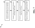
- FIG. 7 is a flowchart 700 of a method of wireless communication.
- the method may be performed by a wireless device that communications based on sidelink.
- the method may be performed by a UE (e.g., the UE 104; the apparatus 802).
- a UE e.g., the UE 104; the apparatus 802.
- One or more aspects illustrated in FIG. 7 may be optional.
- Various implementations may include a method with any combination of the aspects described in connection with FIG. 7 .
- the aspects presented herein may enable the use of different CQI tables for sidelink CSI reports.
- a 704 the wireless device transmits a first set of control information indicating an MCS table.
- the first set of control information is transmitted in a first portion of SCI, SCI-1 transmitted on a PSCCH.
- the first portion of SCI is referred to as a first stage SCI.
- the first set of control information may include aspects described in connection with 505 in FIG. 5 .
- the transmission of the first set of control information may be performed by the MCS Table component 840 of the apparatus 802 in FIG. 8 , for example.
- the wireless device transmits a second set of control information triggering a CSI report from a receiver.
- a CQI table for the CSI report is based on the MCS table indicated in the first set of control information.
- the second set of control information comprises a second portion of the SCI associated with the first portion of the SCI, i.e., SCI-2 that is transmitted on a PSSCH.
- the second portion of SCI is referred to as a second stage SCI.
- the second set of control information may include aspects described in connection with 507 in FIG. 5 .
- the transmission of the second set of control information may be performed by the control information component 842 of the apparatus 802 in FIG. 8 , for example.
- the association between the MCS table and the CQI table may be defined and may be known by both the transmitting wireless device and the receiving wireless device.
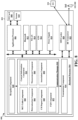
- the apparatus may further include one or more subscriber identity modules (SIM) cards 820, an application processor 806 coupled to a secure digital (SD) card 808 and a screen 810, a Bluetooth module 812, a wireless local area network (WLAN) module 814, a Global Positioning System (GPS) module 816, and/or a power supply 818.
- SIM subscriber identity modules
- SD secure digital
- Bluetooth Bluetooth module
- WLAN wireless local area network
- GPS Global Positioning System
- the baseband processor 804 communicates through the RF transceiver 822 with the UE 104 and/or BS 102/180.
- the baseband processor 804 may include a computer-readable medium / memory.
- the baseband processor 804 is responsible for general processing, including the execution of software stored on the computer-readable medium / memory.
- the communication manager 832 includes an MCS table component 840, a control information component 842, a determination component 844, a measurement component 846, a CSI report component 848, and an association component 850 configured to perform the aspects described in connection with FIGs. 5-7 .
- the MCS table component 840 may be configured to receive or transmit a first set of control information indicating an MCS table, e.g., as described in connection with 604 or 704 in FIG. 6 or FIG. 7 .
- the apparatus 802 may further include a control information component 842 configured to receive or transmit a second set of control information triggering a CSI report, e.g., as described in connection with 606 or 706 in FIG. 6 or FIG. 7 .
- the apparatus 802 further includes a CSI report component 848 configured to receive or transmit the CSI report including CQI that is based on a CQI table associated with the MCS table indicated in the first set of control information, e.g., as described in connection with 614 or 708 in FIG. 6 or FIG. 7 .
- the apparatus may further include a determination component 844 configured to determine the CQI table based on the defined association between the MCS table and the CQI table, e.g., as described in connection with 608 in FIG. 6 .
- the apparatus may further include a measurement component 846 configured to perform channel measurements in response to the second set of control information that triggers the CSI report, e.g., as described in connection with 610 in FIG. 6 .
- the apparatus 802 may further include a CQI component 852 configured to calculate the CQI, for indication in the CSI report, based on the CQI table, e.g., determined by the determination component 844, e.g., as described in connection with 612 in FIG. 6 .
- the apparatus 802 may further include an association component 850 configured to receive or transmit an indication of an association between an MCS table and a CQI table, e.g., as described in connection with 602 or 702 in FIG. 6 or FIG. 7 .
- the association between the MCS table and the CQI table may be defined.
- the apparatus 802 may include a variety of components configured for various functions.
- the apparatus 802 and in particular the baseband processor 804, includes means for receiving a first set of control information indicating an MCS table.
- the apparatus 802 may include means for receiving a second set of control information triggering a CSI report, and means for transmitting the CSI report including the CQI that is based on a CQI table associated with the MCS table indicated in the first set of control information.
- the apparatus 802 may further include means for determining a CQI table for the CSI report based on the MCS table indicated in the first set of control information.
- the apparatus 802 may further include means for receiving the CSI report in response to the second set of control information and based on the CQI table associated with the MCS table indicated in the first set of control information.
- the apparatus 802 may further include means for transmitting an indication of an association between the MCS table and the CQI table.
- the means may be one or more of the components of the apparatus 802 configured to perform the functions recited by the means, e.g., such as described in connection with the algorithm in FIG. 6 or FIG. 7 .
- the apparatus 802 may include the TX Processor 368, the RX Processor 356, and the controller/processor 359.
- the means may be the TX Processor 368, the RX Processor 356, and the controller/processor 359 configured to perform the functions recited by the means.
- the UE may receive an indication over sidelink of an MCS table for sidelink communication with another UE.
- the UE may receive the indication for the MCS table in a first portion of sidelink control information, e.g., which may be referred to as a first stage SCI or SCI-1.
- the UE may receive a trigger for providing a CSI report over sidelink.
- the aperiodic CSI report may be triggered by a second portion of SCI, e.g., which may be referred to as a second stage SCI or SCI-2.
- the UE may determine the CQI table to apply for the CSI report over sidelink based on the MCS table indicated in the first stage SCI.
- Combinations such as "at least one of A, B, or C,” “one or more of A, B, or C,” “at least one of A, B, and C,” “one or more of A, B, and C,” and "A, B, C, or any combination thereof” include any combination of A, B, and/or C, and may include multiples of A, multiples of B, or multiples of C.
- combinations such as “at least one of A, B, or C,” “one or more of A, B, or C,” “at least one of A, B, and C,” “one or more of A, B, and C,” and “A, B, C, or any combination thereof” may be A only, B only, C only, A and B, A and C, B and C, or A and B and C, where any such combinations may contain one or more member or members of A, B, or C.
Landscapes
- Engineering & Computer Science (AREA)
- Signal Processing (AREA)
- Computer Networks & Wireless Communication (AREA)
- Quality & Reliability (AREA)
- Mobile Radio Communication Systems (AREA)
Claims (14)
- Vorrichtung zur drahtlosen Kommunikation an einem drahtlosen Gerät (502), die Folgendes umfasst:Mittel zumEmpfangen (505) eines ersten Satzes von Steuerinformationen in einer ersten Stufe von SCI (Sidelink Control Information), wobei der erste Satz von Steuerinformationen eine MCS-(Modulation and Coding Scheme)-Tabelle angibt;Empfangen (507) eines zweiten Satzes von Steuerinformationen in einer mit der ersten Stufe assoziierten zweiten Stufe der SCI, wobei der zweite Satz von Steuerinformationen einen CSI-(Channel State Information)-Bericht auslöst, ohne eine CQI-(Channel Quality Indicator)-Tabelle anzugeben;Bestimmen (508) der CQI-Tabelle aus mehreren CQI-Tabellen auf der Basis einer definierten Assoziation zwischen der in der ersten Stufe der SCI angegebenen MCS-Tabelle und der CQI-Tabelle; undÜbertragen (511) des durch die zweite Stufe der SCI ausgelösten CSI-Berichts, wobei der CSI-Bericht einen CQI enthält, der auf der CQI-Tabelle basiert, die mit der MCS-Tabelle assoziiert ist, die im ersten Satz von in der ersten Stufe der SCI angegebenen Steuerinformationen angegeben ist.
- Vorrichtung nach Anspruch 1, die Mittel umfasst zumDurchführen von Kanalmessungen als Reaktion auf den zweiten Satz von Steuerinformationen, der den CSI-Bericht auslöst; undBerechnen des im CSI-Bericht angegebenen CQI auf der Basis der CQI-Tabelle.
- Vorrichtung zur drahtlosen Kommunikation an einem drahtlosen Gerät (504), die Folgendes umfasst:Mittel zumÜbertragen (505) eines ersten Satzes von Steuerinformationen in einer ersten Stufe von SCI (Sidelink Control Information), wobei der erste Satz von Steuerinformationen eine MCS-(Modulation and Coding Scheme)-Tabelle angibt;Übertragen (507) eines zweiten Satzes von Steuerinformationen in einer mit der ersten Stufe assoziierten zweiten Stufe der SCI, wobei der zweite Satz von Steuerinformationen einen CSI-(Channel State Information)-Bericht von einem Empfänger auslöst, ohne eine CQI-(Channel Quality Indicator)-Tabelle anzugeben; undEmpfangen (511) des durch die zweite Stufe der SCI ausgelösten CSI-Berichts, wobei der CSI-Bericht eine CQI auf der Basis der CQI-Tabelle aus mehreren CQI-Tabellen enthält, wobei die CQI eine definierte Assoziation zur MCS-Tabelle aufweist, die im ersten Satz von Steuerinformationen angegeben ist, die in der ersten Stufe der SCI enthalten sind.
- Vorrichtung nach Anspruch 2 oder 3, wobei der CSI-Bericht die CQI auf der Basis eines Index einer entsprechenden CQI-Tabelle angibt.
- Vorrichtung nach Anspruch 1 oder 3, wobei ein BLER-(Block Error Rate)-Ziel für den CSI-Bericht auf der CQI-Tabelle basiert.
- Vorrichtung nach Anspruch 1, die Empfangsmittel umfasst, oder Vorrichtung nach Anspruch 3, die Mittel zum Übertragen einer Angabe einer Assoziation zwischen der MCS-Tabelle und der CQI-Tabelle umfasst.
- Vorrichtung nach Anspruch 6, wobei die Angabe in PC5-RRC-(PC5 Radio Ressource Control)-Signalisierung erfolgt.
- Vorrichtung nach Anspruch 6, wobei die Angabe eine Abbildung zwischen mehreren MCS-Tabellen und mehreren CQI-Tabellen umfasst.
- Vorrichtung nach Anspruch 1 oder 3, die ferner einen Transceiver umfasst.
- Verfahren (600) zur drahtlosen Kommunikation an einem drahtlosen Gerät, das Folgendes umfasst:Empfangen (604) eines ersten Satzes von Steuerinformationen in einer ersten Stufe von SCI (Sidelink Control Information), wobei der erste Satz von Steuerinformationen eine MCS-(Modulation and Coding Scheme)-Tabelle angibt;Empfangen (606) eines zweiten Satzes von Steuerinformationen in einer mit der ersten Stufe assoziierten zweiten Stufe der SCI, wobei der zweite Satz von Steuerinformationen einen CSI-(Channel State Information)-Bericht auslöst, ohne eine CQI-(Channel Quality Indicator)-Tabelle anzugeben;Bestimmen der CQI-Tabelle aus mehreren CQI-Tabellen auf der Basis einer definierten Assoziation zwischen der in der ersten Stufe der SCI angegebenen MCS-Tabelle und der CQI-Tabelle; undÜbertragen (614) des durch die zweite Stufe der SCI ausgelösten CSI-Berichts, wobei der CSI-Bericht einen CQI enthält, der auf der CQI-Tabelle basiert, die mit der MCS-Tabelle assoziiert ist, die im ersten Satz von in der ersten Stufe der SCI angegebenen Steuerinformationen angegeben ist.
- Verfahren nach Anspruch 10, das ferner Folgendes beinhaltet:Durchführen (610) von Kanalmessungen als Reaktion auf den zweiten Satz von Steuerinformationen, der den CSI-Bericht auslöst; undBerechnen (612) des im CSI-Bericht angegebenen CQI auf der Basis der CQI-Tabelle.
- Verfahren (700) zur drahtlosen Kommunikation an einem drahtlosen Gerät, das Folgendes beinhaltet:Übertragen (704) eines ersten Satzes von Steuerinformationen in einer ersten Stufe von SCI (Sidelink Control Information), wobei der erste Satz von Steuerinformationen eine MCS-(Modulation and Coding Scheme)-Tabelle angibt;Übertragen (706) eines zweiten Satzes von Steuerinformationen in einer mit der ersten Stufe assoziierten zweiten Stufe der SCI, wobei der zweite Satz von Steuerinformationen einen CSI-(Channel State Information)-Bericht von einem Empfänger auslöst, ohne eine CQI-(Channel Quality Indicator)-Tabelle anzugeben; undEmpfangen (708) des durch die zweite Stufe der SCI ausgelösten CSI-Berichts, wobei der CSI-Bericht einen CQI auf der Basis der CQI-Tabelle aus mehreren CQI-Tabellen enthält, wobei die CQI eine definierte Assoziation zur MCS-Tabelle aufweist, die im ersten Satz von Steuerinformationen angegeben ist, die in der ersten Stufe der SCI enthalten sind.
- Verfahren nach Anspruch 11 oder Anspruch 10, wobei der CSI-Bericht den CQI auf der Basis eines Index einer entsprechenden CQI-Tabelle angibt.
- Verfahren nach Anspruch 10, wobei ein BLER-(Block Error Rate)-Ziel für den CSI-Bericht auf der CQI-Tabelle basiert.
Applications Claiming Priority (3)
| Application Number | Priority Date | Filing Date | Title |
|---|---|---|---|
| US202063029466P | 2020-05-23 | 2020-05-23 | |
| US17/236,518 US20210368489A1 (en) | 2020-05-23 | 2021-04-21 | Cqi table selection in sidelink |
| PCT/US2021/028668 WO2021242456A1 (en) | 2020-05-23 | 2021-04-22 | Cqi table selection in sidelink |
Publications (2)
| Publication Number | Publication Date |
|---|---|
| EP4154444A1 EP4154444A1 (de) | 2023-03-29 |
| EP4154444B1 true EP4154444B1 (de) | 2025-06-25 |
Family
ID=78608060
Family Applications (1)
| Application Number | Title | Priority Date | Filing Date |
|---|---|---|---|
| EP21725317.8A Active EP4154444B1 (de) | 2020-05-23 | 2021-04-22 | Cqi-tabellenauswahl in sidelink |
Country Status (4)
| Country | Link |
|---|---|
| US (1) | US20210368489A1 (de) |
| EP (1) | EP4154444B1 (de) |
| CN (1) | CN115668826B (de) |
| WO (1) | WO2021242456A1 (de) |
Families Citing this family (4)
| Publication number | Priority date | Publication date | Assignee | Title |
|---|---|---|---|---|
| KR102586344B1 (ko) * | 2020-09-29 | 2023-10-11 | 엘지전자 주식회사 | Nr v2x에서 보조 정보를 기반으로 sl 통신을 수행하는 방법 및 장치 |
| US12114317B2 (en) * | 2021-01-26 | 2024-10-08 | Qualcomm Incorporated | Sidelink channel state information (CSI) reporting from a user equipment |
| US12082231B2 (en) * | 2021-11-02 | 2024-09-03 | Qualcomm Incorporated | Sidelink assisted cross link interference determination |
| US20240235721A9 (en) * | 2022-10-25 | 2024-07-11 | Dell Products L.P. | Group link adaptation of 5g multicast broadcast services |
Family Cites Families (25)
| Publication number | Priority date | Publication date | Assignee | Title |
|---|---|---|---|---|
| US8976751B2 (en) * | 2010-07-16 | 2015-03-10 | Lg Electronics Inc. | Method for transmitting control information and apparatus for same |
| CN103988455B (zh) * | 2011-10-12 | 2017-08-25 | 三星电子株式会社 | 移动通信系统中用于发送反向控制信号的方法和设备 |
| EP3972167B1 (de) * | 2012-02-20 | 2023-01-04 | Nokia Solutions and Networks Oy | Steuerung eines modulations-und codierschemas für eine übertragung zwischen einer basisstation und einem benutzergerät |
| EP4207668A1 (de) * | 2013-01-11 | 2023-07-05 | InterDigital Patent Holdings, Inc. | System und verfahren zur adaptiven modulation |
| WO2015041579A1 (en) * | 2013-09-20 | 2015-03-26 | Telefonaktiebolaget L M Ericsson (Publ) | Network node, user equipment and methods for obtaining a modulation and coding scheme |
| CN105850066B (zh) * | 2013-12-27 | 2019-07-19 | Lg电子株式会社 | 报告信道状态信息的方法和装置 |
| EP3089384B1 (de) * | 2013-12-29 | 2019-06-19 | LG Electronics Inc. | Verfahren zur rückmeldung von kanalstatusinformationen in einem drahtloskommunikationssystem und vorrichtung dafür |
| WO2015147592A1 (ko) * | 2014-03-28 | 2015-10-01 | 엘지전자 주식회사 | 무선접속 시스템에서 256qam 지원을 위한 채널상태정보 보고 방법 및 장치 |
| US9161386B1 (en) * | 2014-08-14 | 2015-10-13 | Harris Corporation | Hybrid LMR transceiver with LTE and dynamic antenna control |
| US9590667B1 (en) * | 2015-09-15 | 2017-03-07 | Mediatek Inc. | Method and apparatus for interference cancellation by a user equipment |
| GB2552307A (en) * | 2016-07-12 | 2018-01-24 | Tcl Communication Ltd | Methods and devices for link adaptation under conditions of intermittent interference in wireless communication systems |
| CN108633066B (zh) * | 2017-03-24 | 2021-12-03 | 华为技术有限公司 | 通信方法及其网络设备、终端设备 |
| WO2019027185A1 (ko) * | 2017-08-01 | 2019-02-07 | 엘지전자 주식회사 | Ldpc 코드를 위한 레이트 매칭 수행 방법 및 이를 위한 통신 장치 |
| US10567113B2 (en) * | 2017-08-11 | 2020-02-18 | Samsung Electronics Co., Ltd. | Method and apparatus for channel quality indicator (CQI) and channel state information (CSI) reporting |
| WO2019099319A1 (en) * | 2017-11-15 | 2019-05-23 | Idac Holdings, Inc. | Polar coding system |
| BR112020009846A2 (pt) * | 2017-11-17 | 2020-11-03 | Telefonaktiebolaget Lm Ericsson (Publ) | método desempenhado por um dispositivo sem fio para determinar um esquema de modulação e codificação, dispositivo sem fio, nó de rede e método desempenhado por um nó de rede |
| US10944501B2 (en) * | 2017-12-15 | 2021-03-09 | Mediatek Singapore Pte. Ltd. | Method and apparatus for determining modulation and coding scheme table in mobile communications |
| US11258532B2 (en) * | 2018-01-11 | 2022-02-22 | Kt Corporation | Method and apparatus for data modulation and coding for new radio |
| CN111010254B (zh) * | 2018-01-19 | 2020-11-10 | 华为技术有限公司 | 一种通信方法、通信装置、计算机存储介质 |
| WO2019199070A1 (ko) * | 2018-04-13 | 2019-10-17 | 엘지전자 주식회사 | 무선 통신 시스템에서 하향링크 제어 정보를 이용하여, 전송 블록을 전송하는 방법 및 이를 위한 장치 |
| US10980044B2 (en) * | 2018-07-13 | 2021-04-13 | Qualcomm Incorporated | Rate matching and semi persistent scheduling configuration in wireless communications |
| WO2020171669A1 (ko) * | 2019-02-24 | 2020-08-27 | 엘지전자 주식회사 | 무선통신시스템에서 사이드 링크 단말이 채널 상태보고에 관련된 신호를 송수신하는 방법 및 장치 |
| CN113785612B (zh) * | 2019-05-02 | 2024-05-17 | 三星电子株式会社 | 用于在侧链路通信中测量和报告信道状态的方法和装置 |
| TWI809372B (zh) * | 2020-04-10 | 2023-07-21 | 新加坡商聯發科技(新加坡)私人有限公司 | 側鏈路時隙配置方法與裝置 |
| US20210329604A1 (en) * | 2020-04-20 | 2021-10-21 | Mediatek Singapore Pte. Ltd. | Physical Layer Enhancements for Sidelink Communication |
-
2021
- 2021-04-21 US US17/236,518 patent/US20210368489A1/en active Pending
- 2021-04-22 EP EP21725317.8A patent/EP4154444B1/de active Active
- 2021-04-22 WO PCT/US2021/028668 patent/WO2021242456A1/en not_active Ceased
- 2021-04-22 CN CN202180036999.3A patent/CN115668826B/zh active Active
Also Published As
| Publication number | Publication date |
|---|---|
| EP4154444A1 (de) | 2023-03-29 |
| WO2021242456A1 (en) | 2021-12-02 |
| CN115668826B (zh) | 2024-08-23 |
| US20210368489A1 (en) | 2021-11-25 |
| CN115668826A (zh) | 2023-01-31 |
Similar Documents
| Publication | Publication Date | Title |
|---|---|---|
| US12167384B2 (en) | Sidelink TCI indication for sidelink multi-TRP relaying | |
| US20220103247A1 (en) | Programmable smart repeater with in-band control | |
| WO2021067889A1 (en) | Phase tracking reference signal for multi-transmit/receive points | |
| US12363734B2 (en) | Beamforming in multicast communications | |
| EP4162763B1 (de) | Periodische ressourcenreservierung zur versorgung von aperiodischem verkehr über sidelink | |
| EP4226705B1 (de) | Bandbreitenteilschalter für sidelink-kommunikation | |
| EP4154444B1 (de) | Cqi-tabellenauswahl in sidelink | |
| US11792837B2 (en) | Techniques to facilitate opportunistic CSI for sidelink communication | |
| US20220094389A1 (en) | Switching between different configurations of frequency and beam hopping for single-beam and multi-beam pucch | |
| US11799618B2 (en) | SL BWP mismatch | |
| US20210360609A1 (en) | Utilization of physical resource blocks in a sidelink resource pool | |
| US11838231B2 (en) | Encoding for uplink channel repetition | |
| US12120614B2 (en) | Beam based power control for sidelink | |
| US11924855B2 (en) | Sidelink dormancy | |
| US11778604B2 (en) | MAC-CE for joint sidelink TCI and power control configuration | |
| US12016006B2 (en) | Beam report triggers autonomous beam hopping | |
| US11864274B2 (en) | MAC-CE activation time in multi-path sidelink relay | |
| US11736984B2 (en) | Resource reservation signaling for aperiodic reservations | |
| US20220039139A1 (en) | Beam specific rmsi transmission | |
| US12484039B2 (en) | Soft A/N report triggering for SPS PDSCH | |
| US20240146442A1 (en) | Mcs selection in sbfd | |
| WO2022226759A1 (en) | Delivery of paging for remote ue via rrc signaling |
Legal Events
| Date | Code | Title | Description |
|---|---|---|---|
| STAA | Information on the status of an ep patent application or granted ep patent |
Free format text: STATUS: UNKNOWN |
|
| STAA | Information on the status of an ep patent application or granted ep patent |
Free format text: STATUS: THE INTERNATIONAL PUBLICATION HAS BEEN MADE |
|
| PUAI | Public reference made under article 153(3) epc to a published international application that has entered the european phase |
Free format text: ORIGINAL CODE: 0009012 |
|
| STAA | Information on the status of an ep patent application or granted ep patent |
Free format text: STATUS: REQUEST FOR EXAMINATION WAS MADE |
|
| 17P | Request for examination filed |
Effective date: 20221109 |
|
| AK | Designated contracting states |
Kind code of ref document: A1 Designated state(s): AL AT BE BG CH CY CZ DE DK EE ES FI FR GB GR HR HU IE IS IT LI LT LU LV MC MK MT NL NO PL PT RO RS SE SI SK SM TR |
|
| DAV | Request for validation of the european patent (deleted) | ||
| DAX | Request for extension of the european patent (deleted) | ||
| GRAP | Despatch of communication of intention to grant a patent |
Free format text: ORIGINAL CODE: EPIDOSNIGR1 |
|
| STAA | Information on the status of an ep patent application or granted ep patent |
Free format text: STATUS: GRANT OF PATENT IS INTENDED |
|
| RIC1 | Information provided on ipc code assigned before grant |
Ipc: H04L 5/00 20060101ALI20250107BHEP Ipc: H04L 1/00 20060101AFI20250107BHEP |
|
| INTG | Intention to grant announced |
Effective date: 20250123 |
|
| GRAS | Grant fee paid |
Free format text: ORIGINAL CODE: EPIDOSNIGR3 |
|
| GRAA | (expected) grant |
Free format text: ORIGINAL CODE: 0009210 |
|
| STAA | Information on the status of an ep patent application or granted ep patent |
Free format text: STATUS: THE PATENT HAS BEEN GRANTED |
|
| AK | Designated contracting states |
Kind code of ref document: B1 Designated state(s): AL AT BE BG CH CY CZ DE DK EE ES FI FR GB GR HR HU IE IS IT LI LT LU LV MC MK MT NL NO PL PT RO RS SE SI SK SM TR |
|
| REG | Reference to a national code |
Ref country code: GB Ref legal event code: FG4D |
|
| REG | Reference to a national code |
Ref country code: CH Ref legal event code: EP |
|
| REG | Reference to a national code |
Ref country code: DE Ref legal event code: R096 Ref document number: 602021032847 Country of ref document: DE |
|
| REG | Reference to a national code |
Ref country code: CH Ref legal event code: EP |
|
| REG | Reference to a national code |
Ref country code: IE Ref legal event code: FG4D |
|
| PG25 | Lapsed in a contracting state [announced via postgrant information from national office to epo] |
Ref country code: FI Free format text: LAPSE BECAUSE OF FAILURE TO SUBMIT A TRANSLATION OF THE DESCRIPTION OR TO PAY THE FEE WITHIN THE PRESCRIBED TIME-LIMIT Effective date: 20250625 |
|
| REG | Reference to a national code |
Ref country code: LT Ref legal event code: MG9D |
|
| PG25 | Lapsed in a contracting state [announced via postgrant information from national office to epo] |
Ref country code: NO Free format text: LAPSE BECAUSE OF FAILURE TO SUBMIT A TRANSLATION OF THE DESCRIPTION OR TO PAY THE FEE WITHIN THE PRESCRIBED TIME-LIMIT Effective date: 20250925 Ref country code: GR Free format text: LAPSE BECAUSE OF FAILURE TO SUBMIT A TRANSLATION OF THE DESCRIPTION OR TO PAY THE FEE WITHIN THE PRESCRIBED TIME-LIMIT Effective date: 20250926 |
|
| PG25 | Lapsed in a contracting state [announced via postgrant information from national office to epo] |
Ref country code: BG Free format text: LAPSE BECAUSE OF FAILURE TO SUBMIT A TRANSLATION OF THE DESCRIPTION OR TO PAY THE FEE WITHIN THE PRESCRIBED TIME-LIMIT Effective date: 20250625 |
|
| PG25 | Lapsed in a contracting state [announced via postgrant information from national office to epo] |
Ref country code: HR Free format text: LAPSE BECAUSE OF FAILURE TO SUBMIT A TRANSLATION OF THE DESCRIPTION OR TO PAY THE FEE WITHIN THE PRESCRIBED TIME-LIMIT Effective date: 20250625 |
|
| PG25 | Lapsed in a contracting state [announced via postgrant information from national office to epo] |
Ref country code: RS Free format text: LAPSE BECAUSE OF FAILURE TO SUBMIT A TRANSLATION OF THE DESCRIPTION OR TO PAY THE FEE WITHIN THE PRESCRIBED TIME-LIMIT Effective date: 20250925 |
|
| PG25 | Lapsed in a contracting state [announced via postgrant information from national office to epo] |
Ref country code: LV Free format text: LAPSE BECAUSE OF FAILURE TO SUBMIT A TRANSLATION OF THE DESCRIPTION OR TO PAY THE FEE WITHIN THE PRESCRIBED TIME-LIMIT Effective date: 20250625 |
|
| REG | Reference to a national code |
Ref country code: NL Ref legal event code: MP Effective date: 20250625 |
|
| PG25 | Lapsed in a contracting state [announced via postgrant information from national office to epo] |
Ref country code: NL Free format text: LAPSE BECAUSE OF FAILURE TO SUBMIT A TRANSLATION OF THE DESCRIPTION OR TO PAY THE FEE WITHIN THE PRESCRIBED TIME-LIMIT Effective date: 20250625 |