EP4226705B1 - Bandbreitenteilschalter für sidelink-kommunikation - Google Patents
Bandbreitenteilschalter für sidelink-kommunikation Download PDFInfo
- Publication number
- EP4226705B1 EP4226705B1 EP21777915.6A EP21777915A EP4226705B1 EP 4226705 B1 EP4226705 B1 EP 4226705B1 EP 21777915 A EP21777915 A EP 21777915A EP 4226705 B1 EP4226705 B1 EP 4226705B1
- Authority
- EP
- European Patent Office
- Prior art keywords
- bwp
- sidelink
- resource
- resource pool
- wireless communication
- Prior art date
- Legal status (The legal status is an assumption and is not a legal conclusion. Google has not performed a legal analysis and makes no representation as to the accuracy of the status listed.)
- Active
Links
Images


Classifications
-
- H—ELECTRICITY
- H04—ELECTRIC COMMUNICATION TECHNIQUE
- H04W—WIRELESS COMMUNICATION NETWORKS
- H04W72/00—Local resource management
- H04W72/02—Selection of wireless resources by user or terminal
-
- H—ELECTRICITY
- H04—ELECTRIC COMMUNICATION TECHNIQUE
- H04W—WIRELESS COMMUNICATION NETWORKS
- H04W72/00—Local resource management
- H04W72/04—Wireless resource allocation
- H04W72/044—Wireless resource allocation based on the type of the allocated resource
-
- H—ELECTRICITY
- H04—ELECTRIC COMMUNICATION TECHNIQUE
- H04W—WIRELESS COMMUNICATION NETWORKS
- H04W72/00—Local resource management
- H04W72/20—Control channels or signalling for resource management
-
- H—ELECTRICITY
- H04—ELECTRIC COMMUNICATION TECHNIQUE
- H04W—WIRELESS COMMUNICATION NETWORKS
- H04W76/00—Connection management
- H04W76/20—Manipulation of established connections
- H04W76/28—Discontinuous transmission [DTX]; Discontinuous reception [DRX]
-
- H—ELECTRICITY
- H04—ELECTRIC COMMUNICATION TECHNIQUE
- H04L—TRANSMISSION OF DIGITAL INFORMATION, e.g. TELEGRAPHIC COMMUNICATION
- H04L5/00—Arrangements affording multiple use of the transmission path
- H04L5/0001—Arrangements for dividing the transmission path
- H04L5/0003—Two-dimensional division
- H04L5/0005—Time-frequency
-
- H—ELECTRICITY
- H04—ELECTRIC COMMUNICATION TECHNIQUE
- H04W—WIRELESS COMMUNICATION NETWORKS
- H04W72/00—Local resource management
- H04W72/04—Wireless resource allocation
- H04W72/044—Wireless resource allocation based on the type of the allocated resource
- H04W72/0453—Resources in frequency domain, e.g. a carrier in FDMA
-
- H—ELECTRICITY
- H04—ELECTRIC COMMUNICATION TECHNIQUE
- H04W—WIRELESS COMMUNICATION NETWORKS
- H04W72/00—Local resource management
- H04W72/20—Control channels or signalling for resource management
- H04W72/25—Control channels or signalling for resource management between terminals via a wireless link, e.g. sidelink
-
- H—ELECTRICITY
- H04—ELECTRIC COMMUNICATION TECHNIQUE
- H04W—WIRELESS COMMUNICATION NETWORKS
- H04W92/00—Interfaces specially adapted for wireless communication networks
- H04W92/16—Interfaces between hierarchically similar devices
- H04W92/18—Interfaces between hierarchically similar devices between terminal devices
Definitions
- the present disclosure relates generally to communication systems, and more particularly, to sidelink communication.
- Wireless communication systems are widely deployed to provide various telecommunication services such as telephony, video, data, messaging, and broadcasts.
- Typical wireless communication systems may employ multiple-access technologies capable of supporting communication with multiple users by sharing available system resources. Examples of such multiple-access technologies include code division multiple access (CDMA) systems, time division multiple access (TDMA) systems, frequency division multiple access (FDMA) systems, orthogonal frequency division multiple access (OFDMA) systems, single-carrier frequency division multiple access (SC-FDMA) systems, and time division synchronous code division multiple access (TD-SCDMA) systems.
- CDMA code division multiple access
- TDMA time division multiple access
- FDMA frequency division multiple access
- OFDMA orthogonal frequency division multiple access
- SC-FDMA single-carrier frequency division multiple access
- TD-SCDMA time division synchronous code division multiple access
- 5G New Radio is part of a continuous mobile broadband evolution promulgated by Third Generation Partnership Project (3GPP) to meet new requirements associated with latency, reliability, security, scalability (e.g., with Internet of Things (IoT)), and other requirements.
- 3GPP Third Generation Partnership Project
- 5G NR includes services associated with enhanced mobile broadband (eMBB), massive machine type communications (mMTC), and ultra-reliable low latency communications (URLLC).
- eMBB enhanced mobile broadband
- mMTC massive machine type communications
- URLLC ultra-reliable low latency communications
- Some aspects of 5G NR may be based on the 4G Long Term Evolution (LTE) standard.
- LTE Long Term Evolution
- wireless communication may comprise direct communication between devices based on sidelink, such as in vehicle-to-everything (V2X) and/or other device-to-device (D2D) communication.
- V2X vehicle-to-everything
- D2D device-to-device
- WO 2020/030688 A1 relates to the design of resource pools as they may be used in sidelink communications among users of the wireless communication system, for ex-ample in V2X applications. It discloses a transceiver for a wireless communication system, wherein the wireless communication system configures a set of resources in the wireless communication system.
- the set of resources include a plurality of re-sources to be allocated for respective transmissions to one or more second transceiv-ers in the wireless communication system.
- the set of resources includes a plurality of transmit resource sets and/or receive resource sets, the plurality of transmit/receive resource sets including at least a first transmit/receive resource set and a second transmit/receive resource set.
- the first transmit/receive resource set has a first prop-erty
- the second transmit/receive resource set has a second property, the first property and the second property being different
- the transceiver is configured to use resources from one or more of the plurality of transmit/receive resource sets for the communication.
- a BWP that includes a subset of contiguous resource blocks within a frequency range of a carrier may enable a UE to achieve power savings.
- Sidelink communication that occurs directly between UEs may include unique challenges to avoid interference that are different than communication between a UE and a base station.
- Sidelink communication may include a single BWP for a sidelink carrier, e.g., which may help to avoid interference among sidelink transmissions.
- a single BWP constrains a UE's ability to achieve power savings through communication over narrower bandwidths. Aspects presented herein provide for the configuration of multiple BWPs in a sidelink carrier with each BWP including one or more resource pools.
- processors include microprocessors, microcontrollers, graphics processing units (GPUs), central processing units (CPUs), application processors, digital signal processors (DSPs), reduced instruction set computing (RISC) processors, systems on a chip (SoC), baseband processors, field programmable gate arrays (FPGAs), programmable logic devices (PLDs), state machines, gated logic, discrete hardware circuits, and other suitable hardware configured to perform the various functionality described throughout this disclosure.
- processors in the processing system may execute software.
- Software shall be construed broadly to mean instructions, instruction sets, code, code segments, program code, programs, subprograms, software components, applications, software applications, software packages, routines, subroutines, objects, executables, threads of execution, procedures, functions, etc., whether referred to as software, firmware, middleware, microcode, hardware description language, or otherwise.
- the functions described may be implemented in hardware, software, or any combination thereof. If implemented in software, the functions may be stored on or encoded as one or more instructions or code on a computer-readable medium.
- Computer-readable media includes computer storage media. Storage media may be any available media that can be accessed by a computer.
- such computer-readable media can comprise a random-access memory (RAM), a read-only memory (ROM), an electrically erasable programmable ROM (EEPROM), optical disk storage, magnetic disk storage, other magnetic storage devices, combinations of the types of computer-readable media, or any other medium that can be used to store computer executable code in the form of instructions or data structures that can be accessed by a computer.
- implementations and/or uses may come about via integrated chip implementations and other non-module-component based devices (e.g., end-user devices, vehicles, communication devices, computing devices, industrial equipment, retail/purchasing devices, medical devices, artificial intelligence (AI)-enabled devices, etc.). While some examples may or may not be specifically directed to use cases or applications, a wide assortment of applicability of described aspects may occur.
- non-module-component based devices e.g., end-user devices, vehicles, communication devices, computing devices, industrial equipment, retail/purchasing devices, medical devices, artificial intelligence (AI)-enabled devices, etc.
- Implementations may range a spectrum from chip-level or modular components to non-modular, non-chip-level implementations and further to aggregate, distributed, or original equipment manufacturer (OEM) devices or systems incorporating one or more aspects of the described aspects.
- devices incorporating described aspects and features may also include additional components and features for implementation and practice of claimed and described aspect.
- transmission and reception of wireless signals necessarily includes a number of components for analog and digital purposes (e.g., hardware components including antenna, RF-chains, power amplifiers, modulators, buffer, processor(s), interleaver, adders/summers, etc.). It is intended that aspects described herein may be practiced in a wide variety of devices, chip-level components, systems, distributed arrangements, aggregated or disaggregated components, end-user devices, etc. of varying sizes, shapes, and constitution.
- FIG. 1 is a diagram illustrating an example of a wireless communications system and an access network 100.
- the wireless communications system (also referred to as a wireless wide area network (WWAN)) includes base stations 102, UEs 104, an Evolved Packet Core (EPC) 160, and another core network 190 (e.g., a 5G Core (5GC)).
- the base stations 102 may include macrocells (high power cellular base station) and/or small cells (low power cellular base station).
- the macrocells include base stations.
- the small cells include femtocells, picocells, and microcells.
- a link between a UE 104 and a base station 102 or 180 may be established as an access link, e.g., using a Uu interface. Other communication may be exchanged between wireless devices based on sidelink. For example, some UEs 104 may communicate with each other directly using a device-to-device (D2D) communication link 158. In some examples, the D2D communication link 158 may use the DL/UL WWAN spectrum.
- the D2D communication link 158 may use one or more sidelink channels, such as a physical sidelink broadcast channel (PSBCH), a physical sidelink discovery channel (PSDCH), a physical sidelink shared channel (PSSCH), and a physical sidelink control channel (PSCCH).
- PSBCH physical sidelink broadcast channel
- PSDCH physical sidelink discovery channel
- PSSCH physical sidelink shared channel
- PSCCH physical sidelink control channel
- D2D communication may be through a variety of wireless D2D communications systems, such as for example, WiMedia, Bluetooth, ZigBee, Wi-Fi based on the Institute of Electrical and Electronics Engineers (IEEE) 802.11 standard, LTE, or NR.
- IEEE Institute of Electrical and Electronics Engineers
- sidelink communication may include vehicle-based communication devices that can communicate from vehicle-to-vehicle (V2V), vehicle-to-infrastructure (V2I) (e.g., from the vehicle-based communication device to road infrastructure nodes such as a Road Side Unit (RSU)), vehicle-to-network (V2N) (e.g., from the vehicle-based communication device to one or more network nodes, such as a base station), vehicle-to-pedestrian (V2P), cellular vehicle-to-everything (C-V2X), and/or a combination thereof and/or with other devices, which can be collectively referred to as vehicle-to-anything (V2X) communications.
- V2V vehicle-to-vehicle
- V2I vehicle-to-infrastructure
- RSU Road Side Unit
- V2N vehicle-to-network
- V2P vehicle-to-pedestrian
- C-V2X cellular vehicle-to-everything
- V2X vehicle-
- Sidelink communication may be based on V2X or other D2D communication, such as Proximity Services (ProSe), etc.
- sidelink communication may also be transmitted and received by other transmitting and receiving devices, such as Road Side Unit (RSU) 107, etc.
- Sidelink communication may be exchanged using a PC5 interface, such as described in connection with the example in FIG. 2 .
- RSU Road Side Unit
- Sidelink communication may be exchanged using a PC5 interface, such as described in connection with the example in FIG. 2 .
- the following description, including the example slot structure of FIG 2 may provide examples for sidelink communication in connection with 5G NR, the concepts described herein may be applicable to other similar areas, such as LTE, LTE-A, CDMA, GSM, and other wireless technologies.
- a UE 104 may include a sidelink BWP component 198 configured to receive a configuration of multiple BWPs for sidelink communication with each BWP including one or more sidelink resource pools, and activate a BWP from the multiple BWPs configured for the sidelink communication.
- a sidelink BWP component 198 configured to receive a configuration of multiple BWPs for sidelink communication with each BWP including one or more sidelink resource pools, and activate a BWP from the multiple BWPs configured for the sidelink communication.
- the base stations 102 configured for 4G LTE may interface with the EPC 160 through first backhaul links 132 (e.g., S1 interface).
- the base stations 102 configured for 5G NR may interface with core network 190 through second backhaul links 184.
- UMTS Universal Mobile Telecommunications System
- 5G NR Next Generation RAN
- the base stations 102 may perform one or more of the following functions: transfer of user data, radio channel ciphering and deciphering, integrity protection, header compression, mobility control functions (e.g., handover, dual connectivity), inter-cell interference coordination, connection setup and release, load balancing, distribution for non-access stratum (NAS) messages, NAS node selection, synchronization, radio access network (RAN) sharing, multimedia broadcast multicast service (MBMS), subscriber and equipment trace, RAN information management (RIM), paging, positioning, and delivery of warning messages.
- the base stations 102 may communicate directly or indirectly (e.g., through the EPC 160 or core network 190) with each other over third backhaul links 134 (e.g., X2 interface).
- the first backhaul links 132, the second backhaul links 184, and the third backhaul links 134 may be wired or wireless.
- the base stations 102 may wirelessly communicate with the UEs 104. Each of the base stations 102 may provide communication coverage for a respective geographic coverage area 110. There may be overlapping geographic coverage areas 110. For example, the small cell 102' may have a coverage area 110' that overlaps the coverage area 110 of one or more macro base stations 102.
- a network that includes both small cell and macrocells may be known as a heterogeneous network.
- a heterogeneous network may also include Home Evolved Node Bs (eNBs) (HeNBs), which may provide service to a restricted group known as a closed subscriber group (CSG).
- eNBs Home Evolved Node Bs
- CSG closed subscriber group
- the communication links 120 between the base stations 102 and the UEs 104 may include uplink (UL) (also referred to as reverse link) transmissions from a UE 104 to a base station 102 and/or downlink (DL) (also referred to as forward link) transmissions from a base station 102 to a UE 104.
- the communication links 120 may use multiple-in put and multiple-output (MIMO) antenna technology, including spatial multiplexing, beamforming, and/or transmit diversity.
- the communication links may be through one or more carriers.
- the base stations 102 / UEs 104 may use spectrum up to Y MHz (e.g., 5, 10, 15, 20, 100, 400, etc.
- the component carriers may include a primary component carrier and one or more secondary component carriers.
- a primary component carrier may be referred to as a primary cell (PCell) and a secondary component carrier may be referred to as a secondary cell (SCell).
- the wireless communications system may further include a Wi-Fi access point (AP) 150 in communication with Wi-Fi stations (STAs) 152 via communication links 154, e.g., in a 5 GHz unlicensed frequency spectrum or the like.
- AP Wi-Fi access point
- STAs Wi-Fi stations
- communication links 154 e.g., in a 5 GHz unlicensed frequency spectrum or the like.
- the STAs 152 / AP 150 may perform a clear channel assessment (CCA) prior to communicating in order to determine whether the channel is available.
- CCA clear channel assessment
- the small cell 102' may operate in a licensed and/or an unlicensed frequency spectrum. When operating in an unlicensed frequency spectrum, the small cell 102' may employ NR and use the same unlicensed frequency spectrum (e.g., 5 GHz, or the like) as used by the Wi-Fi AP 150.
- the small cell 102', employing NR in an unlicens ed frequency spectrum, may boost coverage to and/or increase capacity of the access network.
- the electromagnetic spectrum is often subdivided, based on frequency/wavelength, into various classes, bands, channels, etc.
- frequency range designations FR1 410 MHz - 7.125 GHz
- FR2 24.25 GHz - 52.6 GHz
- the frequencies between FR1 and FR2 are often referred to as mid-band frequencies.
- FR1 is often referred to (interchangeably) as a "sub-6 GHz" band in various documents and articles.
- FR2 which is often referred to (interchangeably) as a "millimeter wave” band in documents and articles, despite being different from the extremely high frequency (EHF) band (30 GHz - 300 GHz) which is identified by the International Telecommunications Union (ITU) as a "millimeter wave” band.
- EHF extremely high frequency
- ITU International Telecommunications Union
- FR3 7.125 GHz - 24.25 GHz
- FR3 7.125 GHz - 24.25 GHz
- Frequency bands falling within FR3 may inherit FR1 characteristics and/or FR2 characteristics, and thus may effectively extend features of FR1 and/or FR2 into mid-band frequencies.
- higher frequency bands are currently being explored to extend 5G NR operation beyond 52.6 GHz.
- FR4a or FR4-1 52.6 GHz - 71 GHz
- FR4 52.6 GHz - 114.25 GHz
- FR5 114.25 GHz - 300 GHz.
- Each of these higher frequency bands falls within the EHF band.
- sub-6 GHz or the like if used herein may broadly represent frequencies that may be less than 6 GHz, may be within FR1, or may include mid-band frequencies.
- millimeter wave or the like if used herein may broadly represent frequencies that may include mid-band frequencies, may be within FR2, FR4, FR4-a or FR4-1, and/or FR5, or may be within the EHF band.
- a base station 102 may include and/or be referred to as an eNB, gNodeB (gNB), or another type of base station.
- Some base stations, such as gNB 180 may operate in a traditional sub 6 GHz spectrum, in millimeter wave frequencies, and/or near millimeter wave frequencies in communication with the UE 104.
- the gNB 180 may be referred to as a millimeter wave base station.
- the millimeter wave base station 180 may utilize beamforming 182 with the UE 104 to compensate for the path loss and short range.
- the base station 180 and the UE 104 may each include a plurality of antennas, such as antenna elements, antenna panels, and/or antenna arrays to facilitate the beamforming. Similarly, beamforming may be applied for sidelink communication, e.g., between UEs.
- the base station 180 may transmit a beamformed signal to the UE 104 in one or more transmit directions 182'.
- the UE 104 may receive the beamformed signal from the base station 180 in one or more receive directions 182".
- the UE 104 may also transmit a beamformed signal to the base station 180 in one or more transmit directions.
- the base station 180 may receive the beamformed signal from the UE 104 in one or more receive directions.
- the base station 180 / UE 104 may perform beam training to determine the best receive and transmit directions for each of the base station 180 / UE 104.
- the transmit and receive directions for the base station 180 may or may not be the same.
- the transmit and receive directions for the UE 104 may or may not be the same.
- the EPC 160 may include a Mobility Management Entity (MME) 162, other MMEs 164, a Serving Gateway 166, a Multimedia Broadcast Multicast Service (MBMS) Gateway 168, a Broadcast Multicast Service Center (BM-SC) 170, and a Packet Data Network (PDN) Gateway 172.
- MME Mobility Management Entity
- MBMS Multimedia Broadcast Multicast Service
- BM-SC Broadcast Multicast Service Center
- PDN Packet Data Network
- the MME 162 may be in communication with a Home Subscriber Server (HSS) 174.
- HSS Home Subscriber Server
- the MME 162 is the control node that processes the signaling between the UEs 104 and the EPC 160.
- the MME 162 provides bearer and connection management. All user Internet protocol (IP) packets are transferred through the Serving Gateway 166, which itself is connected to the PDN Gateway 172.
- IP Internet protocol
- the PDN Gateway 172 provides UE IP address allocation as well as other functions.
- the PDN Gateway 172 and the BM-SC 170 are connected to the IP Services 176.
- the IP Services 176 may include the Internet, an intranet, an IP Multimedia Subsystem (IMS), a PS Streaming Service, and/or other IP services.
- the BM-SC 170 may provide functions for MBMS user service provisioning and delivery.
- the BM-SC 170 may serve as an entry point for content provider MBMS transmission, may be used to authorize and initiate MBMS Bearer Services within a public land mobile network (PLMN), and may be used to schedule MBMS transmissions.
- PLMN public land mobile network
- the MBMS Gateway 168 may be used to distribute MBMS traffic to the base stations 102 belonging to a Multicast Broadcast Single Frequency Network (MBSFN) area broadcasting a particular service, and may be responsible for session management (start/stop) and for collecting eMBMS related charging information.
- MMSFN Multicast Broadcast Single Frequency Network
- the core network 190 may include an Access and Mobility Management Function (AMF) 192, other AMFs 193, a Session Management Function (SMF) 194, and a User Plane Function (UPF) 195.
- the AMF 192 may be in communication with a Unified Data Management (UDM) 196.
- the AMF 192 is the control node that processes the signaling between the UEs 104 and the core network 190.
- the AMF 192 provides QoS flow and session management. All user Internet protocol (IP) packets are transferred through the UPF 195.
- the UPF 195 provides UE IP address allocation as well as other functions.
- the UPF 195 is connected to the IP Services 197.
- the IP Services 197 may include the Internet, an intranet, an IP Multimedia Subsystem (IMS), a Packet Switch (PS) Streaming (PSS) Service, and/or other IP services.
- IMS IP Multimedia Subsystem
- PS Packet Switch
- PSS Packet Switch
- the base station may include and/or be referred to as a gNB, Node B, eNB, an access point, a base transceiver station, a radio base station, a radio transceiver, a transceiver function, a basic service set (BSS), an extended service set (ESS), a transmit reception point (TRP), or some other suitable terminology.
- the base station 102 provides an access point to the EPC 160 or core network 190 for a UE 104.
- Examples of UEs 104 include a cellular phone, a smart phone, a session initiation protocol (SIP) phone, a laptop, a personal digital assistant (PDA), a satellite radio, a global positioning system, a multimedia device, a video device, a digital audio player (e.g., MP3 player), a camera, a game console, a tablet, a smart device, a wearable device, a vehicle, an electric meter, a gas pump, a large or small kitchen appliance, a healthcare device, an implant, a sensor/actuator, a display, or any other similar functioning device.
- SIP session initiation protocol
- PDA personal digital assistant
- the UEs 104 may be referred to as IoT devices (e.g., parking meter, gas pump, toaster, vehicles, heart monitor, etc.).
- the UE 104 may also be referred to as a station, a mobile station, a subscriber station, a mobile unit, a subscriber unit, a wireless unit, a remote unit, a mobile device, a wireless device, a wireless communications device, a remote device, a mobile subscriber station, an access terminal, a mobile terminal, a wireless terminal, a remote terminal, a handset, a user agent, a mobile client, a client, or some other suitable terminology.
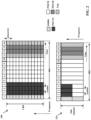
- FIG. 2 includes diagrams 200 and 210 illustrating example aspects of slot structures that may be used for sidelink communication (e.g., between UEs 104, RSU 107, etc.).
- the slot structure may be within a 5G/NR frame structure in some examples. In other examples, the slot structure may be within an LTE frame structure. Although the following description may be focused on 5G NR, the concepts described herein may be applicable to other similar areas, such as LTE, LTE-A, CDMA, GSM, and other wireless technologies.
- the example slot structure in FIG. 2 is merely one example, and other sidelink communication may have a different frame structure and/or different channels for sidelink communication.
- a frame (10 ms) may be divided into 10 equally sized subframes (1 ms).
- Each subframe may include one or more time slots. Subframes may also include mini-slots, which may include 7, 4, or 2 symbols. Each slot may include 7 or 14 symbols, depending on the slot configuration. For slot configuration 0, each slot may include 14 symbols, and for slot configuration 1, each slot may include 7 symbols.
- Diagram 200 illustrates a single resource block of a single slot transmission, e.g., which may correspond to a 0.5 ms transmission time interval (TTI).
- a physical sidelink control channel may be configured to occupy multiple physical resource blocks (PRBs), e.g., 10, 12, 15, 20, or 25 PRBs.
- the PSCCH may be limited to a single sub-channel.
- a PSCCH duration may be configured to be 2 symbols or 3 symbols, for example.
- a sub-channel may comprise 10, 15, 20, 25, 50, 75, or 100 PRBs, for example.
- the resources for a sidelink transmission may be selected from a resource pool including one or more subchannels.
- the resource pool may include between 1-27 subchannels.
- a PSCCH size may be established for a resource pool, e.g., as between 10-100 % of one subchannel for a duration of 2 symbols or 3 symbols.
- the diagram 210 in FIG. 2 illustrates an example in which the PSCCH occupies about 50% of a subchannel, as one example to illustrate the concept of PSCCH occupying a portion of a subchannel.
- the physical sidelink shared channel (PSSCH) occupies at least one subchannel.
- the PSCCH may include a first portion of sidelink control information (SCI), and the PSSCH may include a second portion of SCI in some examples.
- SCI sidelink control information
- a resource grid may be used to represent the frame structure.
- Each time slot may include a resource block (RB) (also referred to as physical RBs (PRBs)) that extends 12 consecutive subcarriers.
- RB resource block
- PRBs physical RBs
- the resource grid is divided into multiple resource elements (REs). The number of bits carried by each RE depends on the modulation scheme.
- some of the REs may comprise control information in PSCCH and some Res may comprise demodulation RS (DMRS).
- DMRS demodulation RS
- At least one symbol may be used for feedback.
- FIG. 2 illustrates examples with two symbols for a physical sidelink feedback channel (PSFCH) with adjacent gap symbols. A symbol prior to and/or after the feedback may be used for turnaround between reception of data and transmission of the feedback.
- PSFCH physical sidelink feedback channel
- the gap enables a device to switch from operating as a transmitting device to prepare to operate as a receiving device, e.g., in the following slot.
- Data may be transmitted in the remaining REs, as illustrated.
- the data may comprise the data message described herein.
- the position of any of the data, DMRS, SCI, feedback, gap symbols, and/or LBT symbols may be different than the example illustrated in FIG. 2 .
- Multiple slots may be aggregated together in some examples.
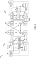
- FIG. 3 is a block diagram 300 of a first wireless communication device 310 in communication with a second wireless communication device 350 based on sidelink.
- the devices 310 and 350 may communicate based on V2X or other D2D communication. The communication may be based on sidelink using a PC5 interface.
- the devices 310 and the 350 may comprise a UE, an RSU, a base station, etc. Packets may be provided to a controller/processor 375 that implements layer 3 and layer 2 functionality.
- Layer 3 includes a radio resource control (RRC) layer
- layer 2 includes a packet data convergence protocol (PDCP) layer, a radio link control (RLC) layer, and a medium access control (MAC) layer.
- RRC radio resource control
- PDCP packet data convergence protocol
- RLC radio link control
- MAC medium access control
- Each stream may then be mapped to an OFDM subcarrier, multiplexed with a reference signal (e.g., pilot) in the time and/or frequency domain, and then combined together using an Inverse Fast Fourier Transform (IFFT) to produce a physical channel carrying a time domain OFDM symbol stream.
- the OFDM stream is spatially precoded to produce multiple spatial streams.
- Channel estimates from a channel estimator 374 may be used to determine the coding and modulation scheme, as well as for spatial processing.
- the channel estimate may be derived from a reference signal and/or channel condition feedback transmitted by the device 350.
- Each spatial stream may then be provided to a different antenna 320 via a separate transmitter 318TX.
- Each transmitter 318TX may modulate an RF carrier with a respective spatial stream for transmission.
- each receiver 354RX receives a signal through its respective antenna 352.
- Each receiver 354RX recovers information modulated onto an RF carrier and provides the information to the receive (RX) processor 356.
- the TX processor 368 and the RX processor 356 implement layer 1 functionality associated with various signal processing functions.
- the RX processor 356 may perform spatial processing on the information to recover any spatial streams destined for the device 350. If multiple spatial streams are destined for the device 350, they may be combined by the RX processor 356 into a single OFDM symbol stream.
- the RX processor 356 then converts the OFDM symbol stream from the time-domain to the frequency domain using a Fast Fourier Transform (FFT).
- FFT Fast Fourier Transform
- the symbols on each subcarrier, and the reference signal, are recovered and demodulated by determining the most likely signal constellation points transmitted by device 310. These soft decisions may be based on channel estimates computed by the channel estimator 358. The soft decisions are then decoded and deinterleaved to recover the data and control signals that were originally transmitted by device 310 on the physical channel. The data and control signals are then provided to the controller/processor 359, which implements layer 3 and layer 2 functionality.
- the controller/processor 359 can be associated with a memory 360 that stores program codes and data.
- the memory 360 may be referred to as a computer-readable medium.
- the controller/processor 359 may provide demultiplexing between transport and logical channels, packet reassembly, deciphering, header decompression, and control signal processing.
- the controller/processor 359 is also responsible for error detection using an ACK and/or NACK protocol to support HARQ operations.
- the controller/processor 359 may provide RRC layer functionality associated with system information (e.g., MIB, SIBs) acquisition, RRC connections, and measurement reporting; PDCP layer functionality associated with header compression / decompression, and security (ciphering, deciphering, integrity protection, integrity verification); RLC layer functionality associated with the transfer of upper layer PDUs, error correction through ARQ, concatenation, segmentation, and reassembly of RLC SDUs, re-segmentation of RLC data PDUs, and reordering of RLC data PDUs; and MAC layer functionality associated with mapping between logical channels and transport channels, multiplexing of MAC SDUs onto TBs, demultiplexing of MAC SDUs from TBs, scheduling information reporting, error correction through HARQ, priority handling, and logical channel prioritization.
- RRC layer functionality associated with system information (e.g., MIB, SIBs) acquisition, RRC connections, and measurement reporting
- PDCP layer functionality associated with header
- Channel estimates derived by a channel estimator 358 from a reference signal or feedback transmitted by device 310 may be used by the TX processor 368 to select the appropriate coding and modulation schemes, and to facilitate spatial processing.
- the spatial streams generated by the TX processor 368 may be provided to different antenna 352 via separate transmitters 354TX. Each transmitter 354TX may modulate an RF carrier with a respective spatial stream for transmission.
- Each receiver 318RX receives a signal through its respective antenna 320.
- Each receiver 318RX recovers information modulated onto an RF carrier and provides the information to a RX processor 370.
- the controller/processor 375 can be associated with a memory 376 that stores program codes and data.
- the memory 376 may be referred to as a computer-readable medium.
- the controller/processor 375 provides demultiplexing between transport and logical channels, packet reassembly, deciphering, header decompression, control signal processing.
- the controller/processor 375 is also responsible for error detection using an ACK and/or NACK protocol to support HARQ operations.
- At least one of the TX processor 368, the RX processor 356, the controller/processor 359, the TX processor 316, the RX processor 370, and the controller/processor 375 may include a sidelink BWP component 198 that is configured to perform the aspects described in connection with FIG. 1 .
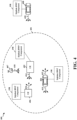
- FIG. 4 illustrates an example 400 of sidelink communication between devices.
- the communication may be based on a slot structure comprising aspects described in connection with FIG. 2 .
- the UE 402 may transmit a sidelink transmission 414, e.g., comprising a control channel (e.g., PSCCH) and/or a corresponding data channel (e.g., PSSCH), that may be received by UEs 404, 406, 408.
- a control channel may include information (e.g., sidelink control information (SCI)) for decoding the data channel including reservation information, such as information about time and/or frequency resources that are reserved for the data channel transmission.
- SCI sidelink control information
- the SCI may indicate a number of TTIs, as well as the RBs that will be occupied by the data transmission.
- the SCI may also be used by receiving devices to avoid interference by refraining from transmitting on the reserved resources.
- the UEs 402, 404, 406, 408 may each be capable of sidelink transmission in addition to sidelink reception. Thus, UEs 404, 406, 408 are illustrated as transmitting sidelink transmissions 413, 415, 416, 420.
- the sidelink transmissions 413, 414, 415, 416, 420 may be unicast, broadcast or multicast to nearby devices.
- UE 404 may transmit communication 413, 415 intended for receipt by other UEs within a range 401 of UE 404, and UE 406 may transmit communication 416.
- RSU 407 may receive communication from and/or transmit communication 418 to UEs 402, 404, 406, 408.
- the UE 402 may provide sidelink control information (SCI) with information for decoding the corresponding data channel.
- SCI may also include information that receiving device may use to avoid interference.
- the SCI may indicate time and frequency resources that will be occupied by the data transmission, may be indicated in a control message from the transmitting device.
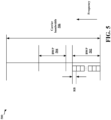
- FIG. 5 illustrates an example frequency diagram 500 showing multiple BWPs (e.g., 502 and 504) within a carrier bandwidth 506.
- Each BWP includes a set of contiguous physical RBs.
- the active BWP(s) of the UE may change dynamically over time, e.g., depending on a traffic pattern between the UE and the base station.
- the use of the BWPs may enable a UE to communicate with the base station over a narrower bandwidth, which may use less power at the UE.
- FIG. 6 illustrates an example of BWP switching 600 for downlink reception by a UE.
- the UE may monitor a narrower BWP (e.g., BWP 1) for a control channel transmission 602 from the base station.
- the control channel 602 does not include a downlink grant for the UE.
- the UE may receive a downlink grant in the control channel 604, the downlink grant indicating BWP 1.
- the UE continues to monitor the narrower bandwidth 608 of BWP 1.
- the UE may receive a control channel transmission 606 and/or data 610 within the frequency resources of the BWP 1.
- the UE may receive a downlink grant in a control channel transmission 612 that indicates a different BWP, e.g., BWP 2.
- BWP e.g., BWP 2.
- the UE switches to monitor the indicated BWP, as shown at 616.
- the UE receives the downlink data 618 on frequency resources of BWP 2.
- the UE may switch back to monitoring the narrower bandwidth of BWP 1. For example, if the UE has not received data and a timer expires, the UE may switch, at 620, back to monitoring BWP 1.
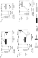
- FIG. 7 illustrates examples of BWP switching for downlink and uplink transmissions from a UE.
- a UE receives downlink control information (DCI) 702 in a first BWP with a downlink grant for the UE to receive PDSCH 704 in a second BWP.
- the UE performs a BWP switch from the first BWP to the second BWP in order to receive the PDSCH.
- the UE transmits feedback 706 (e.g., ACK/NACK) in the second BWP.
- feedback 706 e.g., ACK/NACK
- the RF switching latency for the UE to switch from the first BWP to the second BWP may be provided for with a delay parameter (e.g., k0) between the DCI and the PDSCH reception.
- K1 may provide a delay between the PDSCH reception and the feedback 706.
- a UE receives DCI 712 in a first BWP of a first carrier with a downlink grant for the UE to receive PDSCH 714 in a second BWP of the first carrier.
- the UE performs a BWP switch from the first BWP to the second BWP for the first carrier in order to receive the PDSCH.
- the UE then transmits feedback 716 in a different carrier.
- a delay parameter (e.g., k0) may be configured for a delay between the DCI and the PDSCH reception due to the RF switching latency for the UE to switch from the first BWP to the second BWP.
- the PDSCH may be in the new BWP, e.g., involving a BWP switch from the BWP in which the DCI with the downlink grant is received.
- the UE may apply a new DL/UL BWP pair, e.g., transmitting the ACK (e.g., feedback 706) in a new uplink BWP.
- the UE may receive the PDSCH 714 in the new BWP, and may transmit the feedback in a prior uplink BWP.
- the UE receives the DCI 708, in a first BWP, with an uplink grant for the UE to transmit the PUSCH 710 in a second BWP.
- the UE performs a BWP switch from the first BWP to the second BWP in order to transmit the PUSCH.
- the RF switching latency for the UE to switch from the first BWP to the second BWP may be accommodated by a delay parameter (e.g., k2) for a delay between the DCI and the PUSCH transmission.
- the UE may be configured for a first BWP for a first carrier.
- the UE receives the DCI 718, on a second carrier, with an uplink grant for the UE to transmit PUSCH 720 in a second BWP of the first carrier.
- the UE performs a BWP switch from the first BWP to the second BWP for the first carrier in order to transmit the PUSCH.
- the RF switching latency for the UE to switch from the first BWP to the second BWP on the first carrier may be accommodated with a delay parameter (e.g., k2) that corresponds to a delay between the DCI and the PUSCH transmission.
- a delay parameter e.g., k2
- the sidelink frequency configuration 804 may include a sidelink BWP configuration 808.
- the BWP configuration 808 may include a generic BWP configuration 814.
- the generic BWP configuration 814 may include one or more parameters 820 such as a bandwidth and frequency location for the generic BWP, an SCS and cyclic prefix (CP) for the generic BWP, and/or one or more time domain resources for the generic BWP.
- the sidelink BWP configuration 808 may include one or more resource pool configurations 816. Each resource pool configuration may include one or more resource pools 822 for sidelink communication.
- a BWP may be wider in the frequency domain than a resource pool, and one BWP may include multiple receiving and transmitting resource pools. For example, FIG.
- Each resource pool configuration 824 may include a number of subchannels, subchannel size, starting RB, a code block rate (CBR), modulation and coding scheme (MCS), sensing configuration (e.g., for mode 2 resource allocation), and/or power control configuration, among others.
- reach resource pool configuration may include a maximum number of reception pools and/or transmission pools.
- a sidelink BWP may include a maximum of 16 reception pools and a maximum of 8 transmission pools.
- aspects presented herein provide for multiple BWPs to be configured for a single sidelink carrier.
- the BWPs may improve power savings at a sidelink device while also providing different frequency resources for different sidelink communication. Similar to the BWPs for a UU link, having multiple BWPs for a sidelink carrier may enable some sidelink devices to communicate over a narrower bandwidth, which may improve power savings at the sidelink devices. However, sidelink devices that communicate based on overlapping BWPs may cause interference to each other. Aspects presented herein provide for improved coordination for sidelink communication that is based on multiple BWPs.
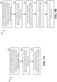
- a configuration of multiple BWPs for sidelink communication is received with each BWP including one or more sidelink resource pools.
- at least one sidelink resource pool may be shared between two or more BWPs, e.g., as illustrated in any of FIGs. 10 or 11 .
- 902 may be performed by a sidelink BWP configuration component 1340 in FIG. 13 .
- a plurality of sidelink resource pools may be configured for a carrier, and each BWP includes one or more configured sidelink resources pools.
- the BWP configuration may indicate the resource pools without separately providing a configuration for each resource pool comprised in the BWP.
- a configuration for each of the plurality of BWPs may include a configuration for each of the one or more sidelink resource pools associated with a corresponding BWP.
- a BWP from the multiple BWPs configured for the sidelink communication is activated.
- a triggering event for the BWP switching may be the change of traffic load among pairs of communication UEs (e.g., when a large amount of data is received at the Tx buffer of the Tx UE). This may indicate to the receiver to switch to a larger BWP, which is similar for the Uu case (i.e., cellular link).
- 904 may be performed by the BWP activation component 1342 in FIG. 13 .
- the indication may be transmitted or received by the BWP switch indication component 1344 of the apparatus 1302.
- the indication of the BWP switch may be transmitted or received in SCI in a first resource pool of the first BWP and indicates a switch to the second BWP.
- the indication may be comprised in a MAC-CE.
- the indication may be transmitted or received in the resource pool associated with BWP indications.
- the indication may comprise a codepoint that maps to a BWP index of the second BWP.
- SCI may indicate a sidelink grant for a sidelink transmission in the first BWP.
- the sidelink device switches to the second BWP after a PSFCH associated with the sidelink transmission in the first BWP.
- a switching time is defined for the BWP switch from a symbol comprising the feedback for a PSCCH that indicates the BWP switch to a first slot in which resource pools in the second BWP become active.
- the sidelink device may not be expected to transmit or receive during the switching time, for example if the first BWP and the second BWP do not share a common resource pool.
- the sidelink device may continue to transmit or receive during the switching time if the first BWP and the second BWP have a common resource pool.
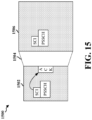
- FIG. 15 illustrates an example timing 1500 of the BWP switch from the first BWP 1502 to the second BWP 1506.
- the BWP switching indication may be included in the SCI of the first BWP 1502.
- the switching time 1504 occurs after the SCI and scheduled PSSCH (i.e., data) and ACK. This is in contrast to the BWP switching for the downlink and uplink transmissions from a UE, shown in FIG. 7 , in which the BWP switching occurs before the data and ACK.
- first BWP and a second BWP on a sidelink carrier have a common resource pool
- the first BWP and the second BWP have one or more of: a SCS, a same CP configuration, time allocation based on a same starting symbol and symbol length, or common transmission occasions for a PSFCH.
- the first BWP and the second BWP may have the common transmission occasions for the PSFCH, wherein each resource pool of the first BWP and the second BWP are configured with a common PSFCH transmission period and slot offset.
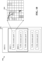
- the activated BWP may include multiple resource pools, and the sidelink device may perform discontinuous reception (DRX) or partial sensing for each of the multiple resource pools of the activated BWP, as illustrated at 907 in FIG. 9B .
- FIG. 14 illustrates an example of a DRX/partial sensing pattern applied to multiple resource pools of a BWP.
- the sidelink device may apply a same DRX pattern for each of the multiple resource pools of the activated BWP.
- the sidelink device may apply a same partial sensing pattern for each of the multiple resource pools of the activated BWP.
- the DRX or partial sensing may be performed by a low power component 1346 of the apparatus 1302.
- FIG. 11B illustrates an example 1102 of two resource pools, each with a distributed RA mode (i.e., Mode 2 RA or sensing based RA).
- each resource pool (resource pool 1 or resource pool 2) may reside in same or different BWP (BWP 1 or BWP 2).
- the first resource pool (resource pool 1) may fully overlap the second resource pool (resource pool 2) of a second BWP (BWP 2) or the first resource pool may not overlap the second resource pool (resource pool 2) of the second BWP (BWP 2).
- the two sidelink resource pools configured with mode 2 resource allocation may not partially overlap.
- the sidelink device monitors for sidelink messages in each reception resource pool configured for the activated BWP.
- the sidelink device selects transmission resources from resources based on each transmission resource pool configured for the activated BWP.
- FIG. 12 illustrates an example 1200 of the BWP switch between nonoverlapping BWPs or partially overlapping BWPs.
- the BWP switch is between BWP 1 and BWP 2.
- the indication of the BWP switch between BWP 1 and BWP 2 may be transmitted or received in SCI in a first resource pool of the first BWP and indicates a switch to the second BWP.
- the indication is comprised in a MAC-CE.
- the indication is transmitted or received in the resource pool associated with BWP indications.
- the indication includes a codepoint that maps to a BWP index of the second BWP.
- the SCI indicates a sidelink grant for a sidelink transmission in the first BWP.
- the sidelink device switches to the second BWP after a PSFCH associated with the sidelink transmission in the first BWP.
- a switching time is defined for the BWP switch from a symbol comprising the feedback for a PSCCH that indicates the BWP switch to a first slot in which resource pools in the second BWP become active.
- the sidelink device is not expected to transmit or receive during the switching time, if the first BWP and the second BWP do not share a common resource pool.
- the sidelink device continues to transmit or receive during the switching time if the first BWP and the second BWP have a common resource pool.
- a configuration that configures a BWP switching indicator may be identified in the SCI associated with the resource pool that is common to the first BWP and the second BWP.
- the UE may be configured whether to include a BWP switching indicator in the corresponding SCI associated with the resource pool.
- the BWP switching indicator may be configured in the common resource pools between multiple BWPs, e.g., rather than in a resource pool that is not common to the BWPs involved in the BWP switch.
- a configuration that configures a mapping between each codepoint of a BWP switching field may be identified in the SCI associated with the resource pool and one or more of the multiple BWPs.
- the configuration may be configured for each resource pool of the resource pools in each BWP.
- the mapping may be part of the configuration 824 for each resource pool described in connection with FIG. 8 .
- a first BWP and a second BWP on a sidelink carrier have at least one common resource pool
- the first BWP and the second BWP have one or more of: a same SCS; a same CP configuration; time allocation based on a same starting symbol and symbol length, or common transmission occasions for a PSFCH.
- the first BWP and the second BWP may have the common transmission occasions for the PSFCH, and each resource pool of the first BWP and the second BWP may be configured with a common PSFCH transmission period and slot offset.
- discontinuous reception may be performed for each of the multiple resource pools of the activated BWP.
- the sidelink device applies a same DRX pattern for each of the multiple resource pools of the activated BWP.
- the activated BWP includes multiple resource pools
- partial sensing is performed for each of the multiple resource pools of the activated BWP.
- the sidelink device applies a same partial sensing pattern for each of the multiple resource pools of the activated BWP.
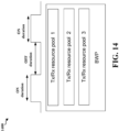
- FIG. 14 illustrates an example low power mode 1400 that includes a pattern of ON durations and OFF durations.
- the pattern may be a DRX pattern with DRX ON durations and DRX OFF durations that are applied to each of resource pools 1, 2, and 3 of the BWP.
- the pattern may be a partial sensing pattern with OFF durations during which the UE is not performing sensing for sidelink messages and ON durations during which the UE performs sensing for sidelink reservations. Both low power modes enable the UE to perform discontinuous reception/sensing for a resource pool over some periods of time.
- the UE may apply DRX/partial sensing jointly for each resource pool of the BWP.
- FIG. 13 is a diagram 1300 illustrating an example of a hardware implementation for an apparatus 1302 for wireless communication.
- the apparatus 1302 is a device that supports sidelink communication.
- the apparatus 1302 may be a UE, a component of a UE, or may implement UE functionality.
- the apparatus 1302 may include a baseband processor 1304 (also referred to as a modem) that may be coupled to an RF transceiver 1322.
- a baseband processor 1304 also referred to as a modem
- the apparatus 1302 may include one or more of a subscriber identity modules (SIM) card 1320, an application processor 1306 coupled to a secure digital (SD) card 1308 and a screen 1310, a Bluetooth module 1312, a wireless local area network (WLAN) module 1314, a Global Positioning System (GPS) module 1316, and/or a power supply 1318.
- SIM subscriber identity modules
- SD secure digital
- GPS Global Positioning System
- the baseband processor 1304 communicates through the RF transceiver 1322 with the UE 104 and/or BS 102/180.
- the baseband processor 1304 may include a computer-readable medium / memory.
- the computer-readable medium / memory may be non-transitory.
- the baseband processor 1304 is responsible for general processing, including the execution of software stored on the computer-readable medium / memory.
- the software when executed by the baseband processor 1304, causes the baseband processor 1304 to perform the various functions described supra.
- the computer-readable medium / memory may also be used for storing data that is manipulated by the baseband processor 1304 when executing software.
- the baseband processor 1304 further includes a reception component 1330, a communication manager 1332, and a transmission component 1334.
- the communication manager 1332 includes the one or more illustrated components.
- the components within the communication manager 1332 may be stored in the computer-readable medium / memory and/or configured as hardware within the baseband processor 1304.
- the baseband processor 1304 may be a component of the device 350 and may include the memory 360 and/or at least one of the TX processor 368, the RX processor 356, and the controller/processor 359.
- the apparatus 1302 may be a modem chip and include just the baseband processor 1304, and in another configuration, the apparatus 1302 may be the entire wireless device (e.g., see 350 of FIG. 3 ) and include the additional modules of the apparatus 1302.
- the communication manager 1332 includes a sidelink BWP configuration component 1340 that is configured to receive a configuration of multiple BWPs for sidelink communication with each BWP including one or more sidelink resource pools, and/or activate a BWP from the multiple BWPs configured for the sidelink communication, e.g., as described in connection with 902 and 904 in FIG. 9A or 9B .
- the communication manager 1332 includes a transmission component 1334 and a reception component 1330, that are configured to transmit or receive the sidelink communication in the resources from the resource pool of the activated BWP once the sidelink BWP configuration component 1340 receives the configuration and activates the BWP, e.g., as described in connection with 906 in FIG. 9A or 9B .
- the apparatus may include additional components that perform the algorithm in the flowchart and illustrations of FIGs. 9A-12 .
- each block in the flowchart and illustrations of FIGs. 9A-12 may be performed by a component and the apparatus may include one or more of those components.
- the components may be one or more hardware components specifically configured to carry out the stated processes/algorithm, implemented by a processor configured to perform the stated processes/algorithm, stored within a computer-readable medium for implementation by a processor, or some combination thereof.
- Combinations such as "at least one of A, B, or C,” “one or more of A, B, or C,” “at least one of A, B, and C,” “one or more of A, B, and C,” and "A, B, C, or any combination thereof” include any combination of A, B, and/or C, and may include multiples of A, multiples of B, or multiples of C.
- combinations such as “at least one of A, B, or C,” “one or more of A, B, or C,” “at least one of A, B, and C,” “one or more of A, B, and C,” and “A, B, C, or any combination thereof” may be A only, B only, C only, A and B, A and C, B and C, or A and B and C, where any such combinations may contain one or more member or members of A, B, or C.
Landscapes
- Engineering & Computer Science (AREA)
- Computer Networks & Wireless Communication (AREA)
- Signal Processing (AREA)
- Mobile Radio Communication Systems (AREA)
Claims (13)
- Verfahren zur drahtlosen Kommunikation an einer Sidelink-Vorrichtung, umfassend:Empfangen einer Konfiguration von mehreren Bandbreitenteilen, BWPs (1000) für Sidelink-Kommunikation, wobei jeder Bandbreitenteil, BWP, einen oder mehrere Sidelink-Ressourcenpools (902) umfasst;Aktivieren eines BWP aus den mehreren BWPs, die für die Sidelink-Kommunikation (904) konfiguriert sind;Senden oder Empfangen der Sidelink-Kommunikation in Ressourcen aus einem Ressourcenpool in dem aktivierten BWP (906);Senden oder Empfangen einer Anzeige eines BWP-Wechsels von einem ersten BWP zu einem zweiten BWP;wobei die Anzeige des BWP-Wechsels in Sidelink-Steuerinformationen, SCI, in einem ersten Ressourcenpool des ersten BWP, der mit BWP-Anzeigen assoziiert ist, gesendet oder empfangen wird und die Anzeige einen Wechsel zu dem zweiten BWP anzeigt; undWechseln zu dem zweiten BWP nach einem physikalischen Sidelink-Rückmeldungskanal, PSFCH, der mit der Sidelink-Übertragung in dem ersten BWP assoziiert ist, wobei eine Wechselzeit für den BWP-Wechsel aus einem Symbol definiert ist, das Rückmeldung für einen physikalischen Sidelink-Steuerkanal, PSCCH, umfasst, der den BWP-Wechsel zu einem ersten Schlitz anzeigt, in dem Ressourcenpools in dem zweiten BWP aktiv werden.
- Verfahren zur drahtlosen Kommunikation nach Anspruch 1, wobei mindestens ein Sidelink-Ressourcenpool von zwei oder mehr BWPs gemeinsam genutzt wird.
- Verfahren zur drahtlosen Kommunikation nach Anspruch 1 oder 2, ferner umfassend:Überwachen auf die Sidelink-Kommunikation in dem einen oder den mehreren Sidelink-Ressourcenpools des aktivierten BWP; undÜberspringen des Überwachens auf die Sidelink-Kommunikation außerhalb des einen oder der mehreren Sidelink-Ressourcenpools des aktivierten BWP.
- Verfahren zur drahtlosen Kommunikation nach einem der Ansprüche 1 bis 3, ferner umfassend:
Durchführen einer Sidelink-Operation in dem einen oder den mehreren Sidelink-Ressourcenpools des aktivierten BWP, wobei die Sidelink-Operation mindestens eines von Folgendem beinhaltet:Auswählen einer Ressource zur Übertragung der Sidelink-Kommunikation aus dem einen oder den mehreren Sidelink-Ressourcenpools des aktivierten BWP,Erfassen von Ressourcenreservierungen basierend auf einem verteilten Ressourcenzuweisungsmodus,Senden einer Ressourcenreservierung basierend auf dem verteilten Ressourcenzuweisungsmodus,Senden der Rückmeldung auf dem PSFCH,Durchführen von Überlastungssteuerung oderBereitstellen von Kanalzustandsinformationen, CSI. - Verfahren zur drahtlosen Kommunikation nach einem der Ansprüche 1 bis 4, wobei eine Vielzahl von Sidelink-Ressourcenpools für einen Träger konfiguriert ist und jeder BWP einen oder mehrere konfigurierte Sidelink-Ressourcenpools beinhaltet.
- Verfahren zur drahtlosen Kommunikation nach einem der Ansprüche 1 bis 5, wobei die Konfiguration für jeden der mehreren BWPs eine Ressourcenpoolkonfiguration für jeden des einen oder der mehreren Sidelink-Ressourcenpools beinhaltet, die mit einem entsprechenden BWP assoziiert sind.
- Verfahren zur drahtlosen Kommunikation nach einem der Ansprüche 1 bis 6, wobei ein erster Ressourcenpool eines ersten BWP und ein zweiter Ressourcenpool eines zweiten BWP für einen zentralisierten Ressourcenzuweisungsmodus sind und der erste Ressourcenpool den zweiten Ressourcenpool mindestens teilweise überlappt, wobei das Verfahren ferner umfasst:
Überspringen des Decodierens mindestens einer Sidelink-Nachricht auf einem zusätzlichen Ressourcenpool eines nicht aktiven BWP. - Verfahren zur drahtlosen Kommunikation nach einem der Ansprüche 1 bis 7, wobei ein erster Ressourcenpool und ein zweiter Ressourcenpool für einen verteilten Ressourcenzuweisungsmodus sind und der erste Ressourcenpool den zweiten Ressourcenpool eines zweiten BWP vollständig überlappt oder den zweiten Ressourcenpool des zweiten BWP nicht überlappt.
- Verfahren zur drahtlosen Kommunikation nach einem der Ansprüche 1 bis 8, wobei die Sidelink-Vorrichtung Übertragungsressourcen aus einem Satz von Ressourcen basierend auf jedem Übertragungsressourcenpool auswählt, der für den aktivierten BWP konfiguriert ist.
- Verfahren zur drahtlosen Kommunikation nach einem der Ansprüche 1 bis 9, wobei die Anzeige des BWP-Wechsels in Sidelink-Steuerinformationen, SCI, in einem gemeinsamen Ressourcenpool, der dem ersten BWP und dem zweiten BWP gemeinsam ist, gesendet oder empfangen wird, wobei einer oder mehrere des PSCCH, eines gemeinsamen physikalischen Sidelink-Kanals, PSSCH, oder des PSFCH, der mit den SCI assoziiert ist, in dem Ressourcenpool gesendet oder empfangen werden, der dem ersten BWP und dem zweiten BWP gemeinsam ist, und der BWP-Wechsel darauf basiert, dass der erste BWP und der zweite BWP den gemeinsamen Ressourcenpool aufweisen.
- Verfahren zur drahtlosen Kommunikation nach einem der Ansprüche 1 bis 10, wobei, wenn ein erster BWP und ein zweiter BWP auf einem Sidelink-Träger einen gemeinsamen Ressourcenpool aufweisen, der erste BWP und der zweite BWP eines oder mehrere aufweisen von:einem gleichen Unterträgerabstand, SCS,einer gleichen zyklischen Präfix-, CP-, Konfiguration,einer Zeitzuweisung basierend auf einem gleichen Startsymbol und einer gleichen Symbollänge, odergemeinsamen Übertragungsgelegenheiten für den PSFCH, wobei der erste BWP und der zweite BWP die gemeinsamen Übertragungsgelegenheiten für den PSFCH aufweisen, wobei jeder Ressourcenpool des ersten BWP und des zweiten BWP mit einer gemeinsamen PSFCH-Übertragungsperiode und einem gemeinsamen Schlitzversatz konfiguriert ist.
- Verfahren zur drahtlosen Kommunikation nach einem der Ansprüche 1 bis 11, wobei der aktivierte BWP mehrere Ressourcenpools beinhaltet, wobei das Verfahren ferner Folgendes umfasst:
Durchführen von diskontinuierlichem Empfang, DRX, oder Teilerfassung für jeden der mehreren Ressourcenpools des aktivierten BWP, wobei die Sidelink-Vorrichtung ein gleiches DRX-Muster oder Teilerfassungsmuster für jeden der mehreren Ressourcenpools des aktivierten BWP anwendet. - Vorrichtung zur drahtlosen Kommunikation an einer Sidelink-Vorrichtung, wobei die Vorrichtung Mittel zum Ausführen des Verfahrens nach einem der Ansprüche 1 bis 12 umfasst.
Applications Claiming Priority (3)
| Application Number | Priority Date | Filing Date | Title |
|---|---|---|---|
| US202063090163P | 2020-10-09 | 2020-10-09 | |
| US17/462,913 US11937214B2 (en) | 2020-10-09 | 2021-08-31 | Bandwidth part switch for sidelink communication |
| PCT/US2021/048605 WO2022076112A1 (en) | 2020-10-09 | 2021-09-01 | Bandwidth part switch for sidelink communication |
Publications (2)
| Publication Number | Publication Date |
|---|---|
| EP4226705A1 EP4226705A1 (de) | 2023-08-16 |
| EP4226705B1 true EP4226705B1 (de) | 2025-03-19 |
Family
ID=81078119
Family Applications (1)
| Application Number | Title | Priority Date | Filing Date |
|---|---|---|---|
| EP21777915.6A Active EP4226705B1 (de) | 2020-10-09 | 2021-09-01 | Bandbreitenteilschalter für sidelink-kommunikation |
Country Status (3)
| Country | Link |
|---|---|
| US (1) | US11937214B2 (de) |
| EP (1) | EP4226705B1 (de) |
| WO (1) | WO2022076112A1 (de) |
Families Citing this family (6)
| Publication number | Priority date | Publication date | Assignee | Title |
|---|---|---|---|---|
| US12096458B2 (en) * | 2020-10-22 | 2024-09-17 | Intel Corporation | MBS service multiplexing and resource configuration |
| US20250274956A1 (en) * | 2022-04-21 | 2025-08-28 | Apple Inc. | Sidelink physical layer structure in nr unlicensed |
| WO2024034991A1 (ko) * | 2022-08-10 | 2024-02-15 | 엘지전자 주식회사 | 무선 통신 시스템에서 신호를 송수신하는 방법 및 장치 |
| US12439401B2 (en) * | 2022-09-14 | 2025-10-07 | Qualcomm Incorporated | Sidelink unified transmission configuration indicator state |
| WO2024197654A1 (zh) * | 2023-03-29 | 2024-10-03 | Oppo广东移动通信有限公司 | 通信方法及通信装置 |
| CN119485692A (zh) * | 2023-08-11 | 2025-02-18 | 华为技术有限公司 | 侧行通信方法和装置 |
Family Cites Families (13)
| Publication number | Priority date | Publication date | Assignee | Title |
|---|---|---|---|---|
| WO2017014514A1 (en) * | 2015-07-17 | 2017-01-26 | Lg Electronics Inc. | Method and apparatus for transmitting data via road side unit in wireless communication system |
| MX2020004752A (es) | 2017-11-22 | 2020-08-20 | Fg innovation co ltd | Operaciones de recepcion discontinua entre varias partes de ancho de banda. |
| US11432369B2 (en) * | 2018-06-19 | 2022-08-30 | Apple Inc. | Reference signal and control information processing in 5G-NR wireless systems |
| CN108830866A (zh) * | 2018-06-25 | 2018-11-16 | 北京达佳互联信息技术有限公司 | 图像分离方法、装置、计算机设备及存储介质 |
| US12219443B2 (en) * | 2018-08-09 | 2025-02-04 | Interdigital Patent Holdings, Inc. | Broadcast, multicast, and unicast on sidelink for 5G eV2X |
| EP3834540A1 (de) | 2018-08-09 | 2021-06-16 | Fraunhofer-Gesellschaft zur Förderung der angewandten Forschung e.V. | Design eines nr-v2x-ressourcenpools |
| CN110830952B (zh) * | 2018-08-10 | 2023-03-28 | 中兴通讯股份有限公司 | 车联网中直通链路的资源配置方法及装置 |
| WO2020085854A1 (ko) * | 2018-10-25 | 2020-04-30 | 엘지전자 주식회사 | 무선 통신 시스템에서 사이드링크 harq 피드백과 관련된 정보에 기반하여 자원선택 윈도우를 결정하는 방법 및 장치 |
| WO2020167773A1 (en) * | 2019-02-12 | 2020-08-20 | Idac Holdings, Inc. | Method for sidelink radio link monitoring and determining radio link failure |
| US11212060B2 (en) * | 2019-04-10 | 2021-12-28 | Hyundai Motor Company | Method and apparatus for reconfiguring bandwidth part in sidelink communication |
| US20220377566A1 (en) * | 2019-10-14 | 2022-11-24 | Sony Group Corporation | Communications devices, and methods |
| EP4108044B1 (de) * | 2020-02-17 | 2024-09-04 | Sony Group Corporation | Kommunikationsvorrichtung, verfahren und schaltung |
| US12167369B2 (en) * | 2020-05-21 | 2024-12-10 | Sharp Kabushiki Kaisha | Method and user equipment for resource selection approach adaptation |
-
2021
- 2021-08-31 US US17/462,913 patent/US11937214B2/en active Active
- 2021-09-01 EP EP21777915.6A patent/EP4226705B1/de active Active
- 2021-09-01 WO PCT/US2021/048605 patent/WO2022076112A1/en not_active Ceased
Also Published As
| Publication number | Publication date |
|---|---|
| US11937214B2 (en) | 2024-03-19 |
| CN116325628A (zh) | 2023-06-23 |
| US20220116914A1 (en) | 2022-04-14 |
| EP4226705A1 (de) | 2023-08-16 |
| WO2022076112A1 (en) | 2022-04-14 |
Similar Documents
| Publication | Publication Date | Title |
|---|---|---|
| US11937182B2 (en) | Sidelink resource allocation with power saving operation | |
| EP4226705B1 (de) | Bandbreitenteilschalter für sidelink-kommunikation | |
| EP4162763B1 (de) | Periodische ressourcenreservierung zur versorgung von aperiodischem verkehr über sidelink | |
| US20220240265A1 (en) | Prioritization of inter-ue coordination information | |
| US11849439B2 (en) | Bandwidth part switch for sidelink communication | |
| US12096400B2 (en) | Resource allocation for sidelink discovery | |
| US11910357B2 (en) | Full duplex sidelink UE indication of selected sidelink resources for overcoming self-interference | |
| US11751198B2 (en) | Discontinuous reception for sidelink | |
| EP4154444B1 (de) | Cqi-tabellenauswahl in sidelink | |
| US20220361196A1 (en) | Sidelink resource selection based on inter-ue coordination information | |
| US11799618B2 (en) | SL BWP mismatch | |
| US11695533B2 (en) | Sidelink resource pool activation and deactivation for power savings | |
| US20210360609A1 (en) | Utilization of physical resource blocks in a sidelink resource pool | |
| US12120614B2 (en) | Beam based power control for sidelink | |
| US11778604B2 (en) | MAC-CE for joint sidelink TCI and power control configuration | |
| US11924855B2 (en) | Sidelink dormancy | |
| US11864274B2 (en) | MAC-CE activation time in multi-path sidelink relay | |
| US20250016805A1 (en) | Congestion control for multi-carrier v2x communication | |
| US20220116913A1 (en) | Multiplexing sidelink ues with different capabilities | |
| WO2023019382A1 (en) | Adapt random selection resources | |
| CN116325628B (en) | Bandwidth portion handover for side-link communication | |
| WO2022226759A1 (en) | Delivery of paging for remote ue via rrc signaling | |
| WO2023077409A1 (en) | Inter-ue coordination information |
Legal Events
| Date | Code | Title | Description |
|---|---|---|---|
| STAA | Information on the status of an ep patent application or granted ep patent |
Free format text: STATUS: UNKNOWN |
|
| STAA | Information on the status of an ep patent application or granted ep patent |
Free format text: STATUS: THE INTERNATIONAL PUBLICATION HAS BEEN MADE |
|
| PUAI | Public reference made under article 153(3) epc to a published international application that has entered the european phase |
Free format text: ORIGINAL CODE: 0009012 |
|
| STAA | Information on the status of an ep patent application or granted ep patent |
Free format text: STATUS: REQUEST FOR EXAMINATION WAS MADE |
|
| 17P | Request for examination filed |
Effective date: 20230215 |
|
| AK | Designated contracting states |
Kind code of ref document: A1 Designated state(s): AL AT BE BG CH CY CZ DE DK EE ES FI FR GB GR HR HU IE IS IT LI LT LU LV MC MK MT NL NO PL PT RO RS SE SI SK SM TR |
|
| DAV | Request for validation of the european patent (deleted) | ||
| DAX | Request for extension of the european patent (deleted) | ||
| GRAP | Despatch of communication of intention to grant a patent |
Free format text: ORIGINAL CODE: EPIDOSNIGR1 |
|
| STAA | Information on the status of an ep patent application or granted ep patent |
Free format text: STATUS: GRANT OF PATENT IS INTENDED |
|
| INTG | Intention to grant announced |
Effective date: 20241112 |
|
| RIC1 | Information provided on ipc code assigned before grant |
Ipc: H04W 92/18 20090101ALN20241101BHEP Ipc: H04W 72/25 20230101ALN20241101BHEP Ipc: H04W 72/0453 20230101ALN20241101BHEP Ipc: H04L 5/00 20060101ALI20241101BHEP Ipc: H04W 72/02 20090101AFI20241101BHEP |
|
| GRAS | Grant fee paid |
Free format text: ORIGINAL CODE: EPIDOSNIGR3 |
|
| GRAA | (expected) grant |
Free format text: ORIGINAL CODE: 0009210 |
|
| STAA | Information on the status of an ep patent application or granted ep patent |
Free format text: STATUS: THE PATENT HAS BEEN GRANTED |
|
| AK | Designated contracting states |
Kind code of ref document: B1 Designated state(s): AL AT BE BG CH CY CZ DE DK EE ES FI FR GB GR HR HU IE IS IT LI LT LU LV MC MK MT NL NO PL PT RO RS SE SI SK SM TR |
|
| REG | Reference to a national code |
Ref country code: GB Ref legal event code: FG4D |
|
| REG | Reference to a national code |
Ref country code: CH Ref legal event code: EP |
|
| REG | Reference to a national code |
Ref country code: DE Ref legal event code: R096 Ref document number: 602021027853 Country of ref document: DE |
|
| REG | Reference to a national code |
Ref country code: IE Ref legal event code: FG4D |
|
| PG25 | Lapsed in a contracting state [announced via postgrant information from national office to epo] |
Ref country code: RS Free format text: LAPSE BECAUSE OF FAILURE TO SUBMIT A TRANSLATION OF THE DESCRIPTION OR TO PAY THE FEE WITHIN THE PRESCRIBED TIME-LIMIT Effective date: 20250619 |
|
| PG25 | Lapsed in a contracting state [announced via postgrant information from national office to epo] |
Ref country code: FI Free format text: LAPSE BECAUSE OF FAILURE TO SUBMIT A TRANSLATION OF THE DESCRIPTION OR TO PAY THE FEE WITHIN THE PRESCRIBED TIME-LIMIT Effective date: 20250319 |
|
| REG | Reference to a national code |
Ref country code: LT Ref legal event code: MG9D |
|
| PG25 | Lapsed in a contracting state [announced via postgrant information from national office to epo] |
Ref country code: NO Free format text: LAPSE BECAUSE OF FAILURE TO SUBMIT A TRANSLATION OF THE DESCRIPTION OR TO PAY THE FEE WITHIN THE PRESCRIBED TIME-LIMIT Effective date: 20250619 |
|
| PG25 | Lapsed in a contracting state [announced via postgrant information from national office to epo] |
Ref country code: HR Free format text: LAPSE BECAUSE OF FAILURE TO SUBMIT A TRANSLATION OF THE DESCRIPTION OR TO PAY THE FEE WITHIN THE PRESCRIBED TIME-LIMIT Effective date: 20250319 |
|
| PG25 | Lapsed in a contracting state [announced via postgrant information from national office to epo] |
Ref country code: LV Free format text: LAPSE BECAUSE OF FAILURE TO SUBMIT A TRANSLATION OF THE DESCRIPTION OR TO PAY THE FEE WITHIN THE PRESCRIBED TIME-LIMIT Effective date: 20250319 |
|
| PG25 | Lapsed in a contracting state [announced via postgrant information from national office to epo] |
Ref country code: GR Free format text: LAPSE BECAUSE OF FAILURE TO SUBMIT A TRANSLATION OF THE DESCRIPTION OR TO PAY THE FEE WITHIN THE PRESCRIBED TIME-LIMIT Effective date: 20250620 Ref country code: BG Free format text: LAPSE BECAUSE OF FAILURE TO SUBMIT A TRANSLATION OF THE DESCRIPTION OR TO PAY THE FEE WITHIN THE PRESCRIBED TIME-LIMIT Effective date: 20250319 |
|
| REG | Reference to a national code |
Ref country code: NL Ref legal event code: MP Effective date: 20250319 |
|
| REG | Reference to a national code |
Ref country code: AT Ref legal event code: MK05 Ref document number: 1778030 Country of ref document: AT Kind code of ref document: T Effective date: 20250319 |
|
| PG25 | Lapsed in a contracting state [announced via postgrant information from national office to epo] |
Ref country code: NL Free format text: LAPSE BECAUSE OF FAILURE TO SUBMIT A TRANSLATION OF THE DESCRIPTION OR TO PAY THE FEE WITHIN THE PRESCRIBED TIME-LIMIT Effective date: 20250319 |
|
| PG25 | Lapsed in a contracting state [announced via postgrant information from national office to epo] |
Ref country code: SE Free format text: LAPSE BECAUSE OF FAILURE TO SUBMIT A TRANSLATION OF THE DESCRIPTION OR TO PAY THE FEE WITHIN THE PRESCRIBED TIME-LIMIT Effective date: 20250319 |
|
| PG25 | Lapsed in a contracting state [announced via postgrant information from national office to epo] |
Ref country code: SM Free format text: LAPSE BECAUSE OF FAILURE TO SUBMIT A TRANSLATION OF THE DESCRIPTION OR TO PAY THE FEE WITHIN THE PRESCRIBED TIME-LIMIT Effective date: 20250319 |
|
| PG25 | Lapsed in a contracting state [announced via postgrant information from national office to epo] |
Ref country code: ES Free format text: LAPSE BECAUSE OF FAILURE TO SUBMIT A TRANSLATION OF THE DESCRIPTION OR TO PAY THE FEE WITHIN THE PRESCRIBED TIME-LIMIT Effective date: 20250319 Ref country code: PT Free format text: LAPSE BECAUSE OF FAILURE TO SUBMIT A TRANSLATION OF THE DESCRIPTION OR TO PAY THE FEE WITHIN THE PRESCRIBED TIME-LIMIT Effective date: 20250721 |
|
| PGFP | Annual fee paid to national office [announced via postgrant information from national office to epo] |
Ref country code: DE Payment date: 20250808 Year of fee payment: 5 |
|
| PG25 | Lapsed in a contracting state [announced via postgrant information from national office to epo] |
Ref country code: PL Free format text: LAPSE BECAUSE OF FAILURE TO SUBMIT A TRANSLATION OF THE DESCRIPTION OR TO PAY THE FEE WITHIN THE PRESCRIBED TIME-LIMIT Effective date: 20250319 Ref country code: IT Free format text: LAPSE BECAUSE OF FAILURE TO SUBMIT A TRANSLATION OF THE DESCRIPTION OR TO PAY THE FEE WITHIN THE PRESCRIBED TIME-LIMIT Effective date: 20250319 |
|
| PGFP | Annual fee paid to national office [announced via postgrant information from national office to epo] |
Ref country code: GB Payment date: 20250814 Year of fee payment: 5 |
|
| PG25 | Lapsed in a contracting state [announced via postgrant information from national office to epo] |
Ref country code: AT Free format text: LAPSE BECAUSE OF FAILURE TO SUBMIT A TRANSLATION OF THE DESCRIPTION OR TO PAY THE FEE WITHIN THE PRESCRIBED TIME-LIMIT Effective date: 20250319 |
|
| PGFP | Annual fee paid to national office [announced via postgrant information from national office to epo] |
Ref country code: FR Payment date: 20250808 Year of fee payment: 5 |
|
| PG25 | Lapsed in a contracting state [announced via postgrant information from national office to epo] |
Ref country code: CZ Free format text: LAPSE BECAUSE OF FAILURE TO SUBMIT A TRANSLATION OF THE DESCRIPTION OR TO PAY THE FEE WITHIN THE PRESCRIBED TIME-LIMIT Effective date: 20250319 Ref country code: EE Free format text: LAPSE BECAUSE OF FAILURE TO SUBMIT A TRANSLATION OF THE DESCRIPTION OR TO PAY THE FEE WITHIN THE PRESCRIBED TIME-LIMIT Effective date: 20250319 |
|
| PG25 | Lapsed in a contracting state [announced via postgrant information from national office to epo] |
Ref country code: RO Free format text: LAPSE BECAUSE OF FAILURE TO SUBMIT A TRANSLATION OF THE DESCRIPTION OR TO PAY THE FEE WITHIN THE PRESCRIBED TIME-LIMIT Effective date: 20250319 |
|
| PG25 | Lapsed in a contracting state [announced via postgrant information from national office to epo] |
Ref country code: SK Free format text: LAPSE BECAUSE OF FAILURE TO SUBMIT A TRANSLATION OF THE DESCRIPTION OR TO PAY THE FEE WITHIN THE PRESCRIBED TIME-LIMIT Effective date: 20250319 |
|
| PG25 | Lapsed in a contracting state [announced via postgrant information from national office to epo] |
Ref country code: IS Free format text: LAPSE BECAUSE OF FAILURE TO SUBMIT A TRANSLATION OF THE DESCRIPTION OR TO PAY THE FEE WITHIN THE PRESCRIBED TIME-LIMIT Effective date: 20250719 |