EP4154344B1 - Elektrochemische anordnung, zugehörige batterie und verfahren - Google Patents
Elektrochemische anordnung, zugehörige batterie und verfahren Download PDFInfo
- Publication number
- EP4154344B1 EP4154344B1 EP21727847.2A EP21727847A EP4154344B1 EP 4154344 B1 EP4154344 B1 EP 4154344B1 EP 21727847 A EP21727847 A EP 21727847A EP 4154344 B1 EP4154344 B1 EP 4154344B1
- Authority
- EP
- European Patent Office
- Prior art keywords
- electrical connection
- tab
- support element
- connection tab
- electrochemical
- Prior art date
- Legal status (The legal status is an assumption and is not a legal conclusion. Google has not performed a legal analysis and makes no representation as to the accuracy of the status listed.)
- Active
Links
Images


Classifications
-
- H—ELECTRICITY
- H01—ELECTRIC ELEMENTS
- H01M—PROCESSES OR MEANS, e.g. BATTERIES, FOR THE DIRECT CONVERSION OF CHEMICAL ENERGY INTO ELECTRICAL ENERGY
- H01M10/00—Secondary cells; Manufacture thereof
- H01M10/04—Construction or manufacture in general
- H01M10/0413—Large-sized flat cells or batteries for motive or stationary systems with plate-like electrodes
-
- H—ELECTRICITY
- H01—ELECTRIC ELEMENTS
- H01M—PROCESSES OR MEANS, e.g. BATTERIES, FOR THE DIRECT CONVERSION OF CHEMICAL ENERGY INTO ELECTRICAL ENERGY
- H01M50/00—Constructional details or processes of manufacture of the non-active parts of electrochemical cells other than fuel cells, e.g. hybrid cells
- H01M50/10—Primary casings; Jackets or wrappings
- H01M50/102—Primary casings; Jackets or wrappings characterised by their shape or physical structure
- H01M50/103—Primary casings; Jackets or wrappings characterised by their shape or physical structure prismatic or rectangular
-
- H—ELECTRICITY
- H01—ELECTRIC ELEMENTS
- H01M—PROCESSES OR MEANS, e.g. BATTERIES, FOR THE DIRECT CONVERSION OF CHEMICAL ENERGY INTO ELECTRICAL ENERGY
- H01M50/00—Constructional details or processes of manufacture of the non-active parts of electrochemical cells other than fuel cells, e.g. hybrid cells
- H01M50/10—Primary casings; Jackets or wrappings
- H01M50/147—Lids or covers
- H01M50/148—Lids or covers characterised by their shape
- H01M50/15—Lids or covers characterised by their shape for prismatic or rectangular cells
-
- H—ELECTRICITY
- H01—ELECTRIC ELEMENTS
- H01M—PROCESSES OR MEANS, e.g. BATTERIES, FOR THE DIRECT CONVERSION OF CHEMICAL ENERGY INTO ELECTRICAL ENERGY
- H01M50/00—Constructional details or processes of manufacture of the non-active parts of electrochemical cells other than fuel cells, e.g. hybrid cells
- H01M50/50—Current conducting connections for cells or batteries
- H01M50/502—Interconnectors for connecting terminals of adjacent batteries; Interconnectors for connecting cells outside a battery casing
- H01M50/503—Interconnectors for connecting terminals of adjacent batteries; Interconnectors for connecting cells outside a battery casing characterised by the shape of the interconnectors
-
- H—ELECTRICITY
- H01—ELECTRIC ELEMENTS
- H01M—PROCESSES OR MEANS, e.g. BATTERIES, FOR THE DIRECT CONVERSION OF CHEMICAL ENERGY INTO ELECTRICAL ENERGY
- H01M50/00—Constructional details or processes of manufacture of the non-active parts of electrochemical cells other than fuel cells, e.g. hybrid cells
- H01M50/50—Current conducting connections for cells or batteries
- H01M50/502—Interconnectors for connecting terminals of adjacent batteries; Interconnectors for connecting cells outside a battery casing
- H01M50/507—Interconnectors for connecting terminals of adjacent batteries; Interconnectors for connecting cells outside a battery casing comprising an arrangement of two or more busbars within a container structure, e.g. busbar modules
-
- H—ELECTRICITY
- H01—ELECTRIC ELEMENTS
- H01M—PROCESSES OR MEANS, e.g. BATTERIES, FOR THE DIRECT CONVERSION OF CHEMICAL ENERGY INTO ELECTRICAL ENERGY
- H01M50/00—Constructional details or processes of manufacture of the non-active parts of electrochemical cells other than fuel cells, e.g. hybrid cells
- H01M50/50—Current conducting connections for cells or batteries
- H01M50/502—Interconnectors for connecting terminals of adjacent batteries; Interconnectors for connecting cells outside a battery casing
- H01M50/514—Methods for interconnecting adjacent batteries or cells
- H01M50/516—Methods for interconnecting adjacent batteries or cells by welding, soldering or brazing
-
- H—ELECTRICITY
- H01—ELECTRIC ELEMENTS
- H01M—PROCESSES OR MEANS, e.g. BATTERIES, FOR THE DIRECT CONVERSION OF CHEMICAL ENERGY INTO ELECTRICAL ENERGY
- H01M50/00—Constructional details or processes of manufacture of the non-active parts of electrochemical cells other than fuel cells, e.g. hybrid cells
- H01M50/50—Current conducting connections for cells or batteries
- H01M50/531—Electrode connections inside a battery casing
- H01M50/533—Electrode connections inside a battery casing characterised by the shape of the leads or tabs
-
- H—ELECTRICITY
- H01—ELECTRIC ELEMENTS
- H01M—PROCESSES OR MEANS, e.g. BATTERIES, FOR THE DIRECT CONVERSION OF CHEMICAL ENERGY INTO ELECTRICAL ENERGY
- H01M50/00—Constructional details or processes of manufacture of the non-active parts of electrochemical cells other than fuel cells, e.g. hybrid cells
- H01M50/50—Current conducting connections for cells or batteries
- H01M50/531—Electrode connections inside a battery casing
- H01M50/536—Electrode connections inside a battery casing characterised by the method of fixing the leads to the electrodes, e.g. by welding
-
- H—ELECTRICITY
- H01—ELECTRIC ELEMENTS
- H01M—PROCESSES OR MEANS, e.g. BATTERIES, FOR THE DIRECT CONVERSION OF CHEMICAL ENERGY INTO ELECTRICAL ENERGY
- H01M50/00—Constructional details or processes of manufacture of the non-active parts of electrochemical cells other than fuel cells, e.g. hybrid cells
- H01M50/50—Current conducting connections for cells or batteries
- H01M50/531—Electrode connections inside a battery casing
- H01M50/538—Connection of several leads or tabs of wound or folded electrode stacks
-
- H—ELECTRICITY
- H01—ELECTRIC ELEMENTS
- H01M—PROCESSES OR MEANS, e.g. BATTERIES, FOR THE DIRECT CONVERSION OF CHEMICAL ENERGY INTO ELECTRICAL ENERGY
- H01M50/00—Constructional details or processes of manufacture of the non-active parts of electrochemical cells other than fuel cells, e.g. hybrid cells
- H01M50/50—Current conducting connections for cells or batteries
- H01M50/531—Electrode connections inside a battery casing
- H01M50/54—Connection of several leads or tabs of plate-like electrode stacks, e.g. electrode pole straps or bridges
-
- H—ELECTRICITY
- H01—ELECTRIC ELEMENTS
- H01M—PROCESSES OR MEANS, e.g. BATTERIES, FOR THE DIRECT CONVERSION OF CHEMICAL ENERGY INTO ELECTRICAL ENERGY
- H01M50/00—Constructional details or processes of manufacture of the non-active parts of electrochemical cells other than fuel cells, e.g. hybrid cells
- H01M50/50—Current conducting connections for cells or batteries
- H01M50/543—Terminals
- H01M50/547—Terminals characterised by the disposition of the terminals on the cells
- H01M50/55—Terminals characterised by the disposition of the terminals on the cells on the same side of the cell
-
- Y—GENERAL TAGGING OF NEW TECHNOLOGICAL DEVELOPMENTS; GENERAL TAGGING OF CROSS-SECTIONAL TECHNOLOGIES SPANNING OVER SEVERAL SECTIONS OF THE IPC; TECHNICAL SUBJECTS COVERED BY FORMER USPC CROSS-REFERENCE ART COLLECTIONS [XRACs] AND DIGESTS
- Y02—TECHNOLOGIES OR APPLICATIONS FOR MITIGATION OR ADAPTATION AGAINST CLIMATE CHANGE
- Y02E—REDUCTION OF GREENHOUSE GAS [GHG] EMISSIONS, RELATED TO ENERGY GENERATION, TRANSMISSION OR DISTRIBUTION
- Y02E60/00—Enabling technologies; Technologies with a potential or indirect contribution to GHG emissions mitigation
- Y02E60/10—Energy storage using batteries
-
- Y—GENERAL TAGGING OF NEW TECHNOLOGICAL DEVELOPMENTS; GENERAL TAGGING OF CROSS-SECTIONAL TECHNOLOGIES SPANNING OVER SEVERAL SECTIONS OF THE IPC; TECHNICAL SUBJECTS COVERED BY FORMER USPC CROSS-REFERENCE ART COLLECTIONS [XRACs] AND DIGESTS
- Y02—TECHNOLOGIES OR APPLICATIONS FOR MITIGATION OR ADAPTATION AGAINST CLIMATE CHANGE
- Y02P—CLIMATE CHANGE MITIGATION TECHNOLOGIES IN THE PRODUCTION OR PROCESSING OF GOODS
- Y02P70/00—Climate change mitigation technologies in the production process for final industrial or consumer products
- Y02P70/50—Manufacturing or production processes characterised by the final manufactured product
Definitions
- the present invention relates to an electrochemical assembly, of the type comprising the characteristics of the preamble of claim 1.
- the electrochemical assembly comprises two stacks of electrochemical cells, each of which comprises an electrical connection tab.
- the tabs are arranged one on top of the other and are supported by a support plate arranged on both stacks.
- the tabs extend on either side around the edges of the support plate.
- the tabs and the support plate are stacked on both stacks of electrochemical cells.
- the aim of the invention is to provide an electrochemical assembly that is easy and economical to manufacture.
- the aim of the invention is in particular to provide a reliable, economical and space-saving connection between the electrodes and the terminals of the electrochemical assembly.
- the invention relates to an electrochemical assembly comprising the characteristics of claim 1.
- a battery according to the invention is shown, designated by the general reference 2.
- the battery 2 is shown in perspective, in the exploded state.
- Battery 2 is an electrochemical battery, as used in electric vehicles. However, other areas of application for Battery 2 are conceivable, such as energy storage, electric mobility, aviation, and railways.
- Battery 2 comprises a housing 4, a cover 6 and an electrochemical assembly 8.
- the or each of the PL/PT/PE planes extends in this case in a corresponding plane of symmetry of the battery.
- the cover 6 is provided with an electrical connection terminal of a first polarity 14 and an electrical connection terminal of a second polarity 16.
- the cover 6 is in this case a substantially rectangular plate.
- the electrochemical assembly 8 comprises a first stack of electrochemical elements 18 which is provided with a first electrical connection tab 20.
- the electrochemical assembly 8 comprises a second stack of electrochemical elements 22 which is provided with a second electrical connection tab 24.
- Each stack of electrochemical elements is commonly called a “Stack”.
- the first stack of electrochemical elements 18 and the second stack of electrochemical elements 22 are arranged in the housing 4 and are electrically connected to each other in a parallel electrical connection.
- the battery 2 may comprise any number of electrochemical elements 8.
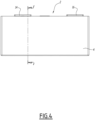
- the first electrical connection tab 20 is formed from a superposition of metal strips which are connected or formed in one piece with current collectors of the first stack of electrochemical elements 18.
- the second electrical connection tab 24 is formed from a superposition of metal strips which are connected or formed in one piece with current collectors of the second stack of electrochemical elements 22. This is shown schematically in the Figure 6 .
- the first electrical connection tab 20 extends substantially parallel to the PE stacking plane.
- the second electrical connection tab 24 extends substantially parallel to the PE stacking plane.
- substantially parallel means parallelism within manufacturing tolerances, for example between 0° and 3°.
- the or each of the electrical connection tabs is an unbent tab and is substantially flat over its entire extent.
- the first stack of electrochemical elements 18 and the second stack of electrochemical elements 22 extend on either side of the PE stacking plane.
- the first electrical connection tab 20 and/or the second electrical connection tab 24 are arranged on the corresponding stack of electrochemical elements on the side remote from the other stack of electrochemical elements.
- the first electrical connection tab 20 and/or the second electrical connection tab 24 are therefore arranged closer to a free face of the stack of electrochemical elements adjacent to the casing 4 than to the longitudinal plane PL.
- the electrochemical assembly 8 comprises a first common connection element 26 (also called a “lug” or “collector”), electrically connecting the first electrical connection tab 20 and the second electrical connection tab 24.
- the first connection element 26 is for example formed from a folded sheet metal.
- the common connection element 26 is fixed and electrically connected to the electrical connection terminal 14 and electrically connects the first electrical connection tab 20 and the second electrical connection tab 24 to the electrical connection terminal 14.
- the first common connection element 26 comprises a first electrical connection rib 28 fixed to the first electrical connection tab 20, and a second electrical connection rib 30, fixed to the second electrical connection tab 24.
- each of the electrical connection ribs has a greater thickness than the electrical connection tab, respectively than each of the strips of the electrical connection tab, to which this rib is associated and fixed.
- the first common connection element 26 comprises an electrical connection core 32 disposed between the first electrical connection rib and the second electrical connection rib.
- the electrical connection core 32 comprises a terminal portion 34 and a terminal portion 36, the terminal portion being offset towards the stack of electrochemical elements 22 relative to the terminal portion 24. In this case, the electrical connection core 32 is stepped (see Figure 2 ).
- the first electrical connection rib 28 and the second electrical connection rib 30 are disposed between the first and second electrical connection tabs 20, 24.
- the first electrical connection rib 28 extends substantially parallel to the PE stacking plane.
- the second electrical connection rib 30 extends substantially parallel to the PE stacking plane.
- first electrical connection rib 28, the first electrical connection tab 20, the second connection rib electrical 30, the second electrical connection tab 24 are offset from the terminal portion 36 respectively from the associated terminal 14. This leads to a compact structure of the battery 2.
- the casing 4 is for example a rectangular parallelepiped casing formed of metal or a thermoplastic material. Alternatively, the casing 4 has a cylindrical shape with a circular section. The casing 4 has walls which are less deformable than the walls of the stacks of electrochemical elements 18 and 22.
- the electrochemical assembly comprises a first support member 40, in particular a single-piece member, which forms a first support element 42, a second support element 44 and which comprises a central core 46 arranged between the first support element and the second support element.
- the first support element 42 and the second support element 44 define a support plane PS, which extends perpendicular to the stacking plane PE and perpendicular to the transverse plane PT (see Figure 6 ).
- the support plane PS is generally a plane in which the first support element 42 and the second support element 44 are located.
- the first electrical connection tab 20 is arranged between the first electrical connection rib 28 and the first support element 42.
- the second electrical connection tab 24 is arranged between the second electrical connection rib 30 and the second support element 44.
- the first support element 42 and/or the second support element 44 is for example each a support tab, in particular extending parallel to the associated electrical connection tab 20, 24.
- the first support element 42 and/or the second support element 44 have a shape different from a tab shape.
- each of the support elements has a greater thickness than the electrical connection tab, respectively than each of the strips of the electrical connection tab, to which this support element is associated and fixed.
- Each support element is adapted to support the electrical connection tab and the associated electrical connection rib during the operation of fixing the electrical connection tab to the associated electrical connection rib.
- the support elements prevent deformation of the electrical connection tab/electrical connection rib assembly during the welding or brazing operation.
- the support elements reduce the risk of holes forming in the connection tabs during the welding or brazing operation.
- the associated electrical connection rib, electrical connection tab and support element thus form a sandwich structure.
- the central core 46 is arranged substantially perpendicular to the support plane PS.
- first electrical connection tab 20 and the second electrical connection tab 24 are arranged between the first and second support elements 42, 44 (see Figure 6 ).
- the first common connection element 26 is fixed to the first electrical connection tab 20 by a material connection, in particular by laser welding.
- the first electrical connection tab 20 is fixed to the first support element 42 by a material connection, in particular by laser welding, and in particular by the same material connection as the first common connection element.
- the first common connection element 26 is fixed to the second electrical connection tab 24 by a material bond, in particular by laser welding.
- the second electrical connection tab 24 is fixed to the second support element 44 by a material bond, in particular by laser welding, and in particular by the same material bond as the first common connection element.
- the structure of the electrical connection tabs and the electrical connection element connects the stacks of electrochemical elements along the tabs in a space-saving manner along the central axis A-A.
- the structure of battery 2 is substantially symmetrical.
- first stack of electrochemical elements 18 is provided with a third electrical connection tab 60 of a second polarity
- second stack of electrochemical elements 22 is provided with a fourth electrical connection tab 64 of the second polarity.
- the electrochemical assembly comprises a second common connection element 66, electrically connecting the third electrical connection tab 60 and the fourth electrical connection tab 66 and adapted to electrically connect the third electrical connection tab and the fourth electrical connection tab to the electrical connection terminal 16 of the second polarity.
- the first common connection element 26 and the second common connection element 66 have an identical shape.
- the second common connection element 66 therefore has the same structural characteristics as the first common connection element 26.
- the second common connection element 66 includes a third electrical connection rib 68 attached to the third electrical connection tab 60, and a fourth electrical connection rib 70, attached to the fourth electrical connection tab 64.
- the second common connection element 66 comprises an electrical connection core 72 disposed between the third electrical connection rib and the fourth electrical connection rib.
- the electrical connection core 72 comprises a terminal portion 74 and a terminal portion 76, the terminal portion 76 being offset towards the stack of electrochemical elements 22 relative to the terminal portion 24. In this case, the electrical connection core 72 is stepped (see Figure 2 ).
- the electrochemical assembly 8 comprises a second support member 80, in particular a single-piece member, which forms a third support element 82 and a fourth support element 84 and which comprises at least one second central core 86 arranged between the third support element and the fourth support element.
- the third electrical connection tab 60 is disposed between the third electrical connection rib 68 and the third support member, and the fourth electrical connection tab 64 is disposed between the fourth electrical connection rib 70 and the fourth support member.
- the third electrical connection tab 60 and/or the third electrical connection rib extend substantially parallel to the stacking plane (PE) and the fourth electrical connection tab 64 and the fourth electrical connection rib extend substantially parallel to the stacking plane (PE).
- the first common connecting element 26 and the second common connecting element 66 are arranged in a plane symmetric configuration with respect to a plane of symmetry (PT).
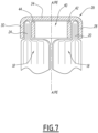
- FIG. 7 schematically represents a section of an electrochemical assembly according to a variant of the battery according to the invention above. This variant differs from what has been described previously only in the following. Similar elements bear the same references.
- the first support element 42 and the second support element 44 are disposed between the first and second electrical connection tabs 20, 24. Also, the first electrical connection tab 20 and the second electrical connection tab 24 are disposed between the first electrical connection rib 28 and the second electrical connection rib 30.
- the first support member 40 is arranged between the first electrical connection rib 28 and the second electrical connection rib 30.
- the configuration is therefore reversed with respect to that of the Figure 6 .
- the first organ support 40 advantageously has the shape of a rectangular frame in order to avoid deformation during the fixing step.
- second support member 80 and the second common connection element 66 may have a configuration identical to that of this Figure 7 or the configuration of the Figure 6 , described above.
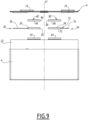
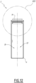
- FIG. 8 to 13 a second embodiment of the battery according to the invention is shown.
- Figures 8 to 13 correspond to the Figures 1 to 7 .
- This second embodiment differs from the first embodiment only in the following. Similar elements bear the same references.
- the central core 46 of the first support member 40 is arranged substantially parallel to the support plane PS.
- the central core 86 of the second support member 80 is arranged substantially parallel to the support plane PS.
- the central core 46 is connected along the long edges of the support elements 42, 44 respectively 82, 84. Also, the central core 46, respectively 86, covers the terminal portion 34, respectively 74, of the electrical connection core 32, respectively 72, and extends parallel thereto.
- the support elements 42, 44 and/or 82, 84 can be arranged as in the variant of the Figure 7 .
- the common connection element for example element 26, comprises only a single electrical connection rib, for example rib 28.
- a single stack of electrochemical elements is connected to the common connection element, or the other stack of electrochemical elements is connected by means other than an electrical connection rib to the common connection element.
- the support member may comprise only one support element or be formed by this support element.
- the or each electrical connection tab and the associated electrical connection rib extend relative to the stacking plane (PE) at an angle of between 0° and 45°.
- the first electrical connection tab and the first electrical connection rib extend at an angle either parallel or oblique (e.g. between 0° and 60°) to the PE stacking plane.
- the fixing and connection of the first electrical connection rib 28 and the first support element 42 to the first electrical connection tab and the fixing and connection of the second electrical connection rib 30 and the second support element 44 to the second electrical connection tab are carried out simultaneously.
- the battery structure is compact while leading to a reliable electrical connection between the various elements.
- the battery is also easy and economical to manufacture, particularly due to the arrangement of the electrical connection tabs and the characteristics of the common connection elements and support members.
Landscapes
- Chemical & Material Sciences (AREA)
- Chemical Kinetics & Catalysis (AREA)
- Electrochemistry (AREA)
- General Chemical & Material Sciences (AREA)
- Engineering & Computer Science (AREA)
- Manufacturing & Machinery (AREA)
- Connection Of Batteries Or Terminals (AREA)
Claims (13)
- Elektrochemische Anordnung der Art, umfassend:einen ersten Stapel von elektrochemischen Elementen (18), ausgestattet mit einer ersten elektrischen Verbindungslasche (20) mit einer ersten Polarität,wobei sich der erste Stapel von elektrochemischen Elementen gemäß einer Stapelebene (PE) erstreckt,ein erstes gemeinsames Verbindungselement (26), das ausgelegt ist, um die erste elektrische Verbindungslasche elektrisch mit einer ersten elektrischen Verbindungsklemme (14) mit der ersten Polarität elektrisch zu verbinden,wobei das erste gemeinsame Verbindungselement eine erste elektrische Verbindungsrippe (28) umfasst, die an die erste elektrische Verbindungslasche fixiert ist,wobei die erste elektrochemische Anordnung ein erstes Stützelement (42) umfasst,wobei die erste elektrische Verbindungslasche (20) zwischen der ersten elektrischen Verbindungsrippe (28) und dem ersten Stützelement (42) angeordnet ist, wobei die erste elektrochemische Anordnung Folgendes umfasst:einen zweiten Stapel von elektrochemischen Elementen (22), der mit einer zweiten elektrischen Verbindungslasche (24) mit der ersten Polarität ausgestattet ist,wobei sich der zweite Stapel von elektrochemischen Elementen gemäß der Stapelebene (PE) erstreckt,wobei das erste gemeinsame Verbindungselement (26) die erste elektrische Verbindungslasche und die zweite elektrische Verbindungslasche elektrisch verbindet und ausgelegt ist, um die zweite elektrische Verbindungslasche mit der elektrischen Verbindungsklemme (14) mit der ersten Polarität zu verbinden,wobei das erste gemeinsame Verbindungselement (26) eine zweite elektrische Verbindungsrippe (30) umfasst, die an die zweite elektrische Verbindungslasche fixiert ist,wobei die elektrochemische Anordnung ein zweites Stützelement (44) umfasst,wobei die zweite elektrische Verbindungslasche zwischen der zweiten elektrischen Verbindungsrippe und dem zweiten Stützelement angeordnet ist,dadurch gekennzeichnet, dassdie elektrochemische Anordnung ein erstes Stützorgan (40) umfasst, das das erste Stützelement und das zweite Stützelement bildet, und das mindestens einen zentralen Kern (46) umfasst, der zwischen dem ersten Stützelement und dem zweiten Stützelement angeordnet ist.
- Elektrochemische Anordnung nach Anspruch 1, wobei die erste elektrische Verbindungslasche und die erste elektrische Verbindungsrippe sich im Wesentlichen parallel zu der Stapelebene (PE) erstrecken.
- Elektrochemische Anordnung nach Anspruch 1 oder 2, wobei
die zweite elektrische Verbindungslasche und die zweite elektrische Verbindungsrippe sich im Wesentlichen parallel zur Stapelebene (PE) erstrecken. - Elektrochemische Anordnung nach einem der Ansprüche 1 bis 3, wobei der zentrale Kern entweder im Wesentlichen senkrecht oder im Wesentlichen parallel zu einer Stützebene (PS) angeordnet ist, die von dem ersten Stützelement und dem zweiten Stützelement definiert ist.
- Elektrochemische Anordnung nach einem der Ansprüche 1 bis 4, wobeidas erste gemeinsame Verbindungselement (26) an die erste elektrische Verbindungslasche (20) durch eine Materialverbindung fixiert ist, insbesondere durch Laserschweißen, und die erste elektrische Verbindungslasche (20) an das erste Stützelement durch eine Materialverbindung fixiert ist, insbesondere durch Laserschweißen,
und/oderdas erste gemeinsame Verbindungselement (26) an die zweite elektrische Verbindungslasche (24) durch eine Materialverbindung fixiert ist, insbesondere durch Laserschweißen, und die zweite elektrische Verbindungslasche (24) an das zweite Stützelement durch eine Materialverbindung fixiert ist, insbesondere durch Laserschweißen. - Elektrochemische Anordnung nach einem der vorhergehenden Ansprüche, wobei das erste gemeinsame Verbindungselement (26) einen elektrischen Verbindungskern (32) umfasst, der zwischen der ersten elektrischen Verbindungsrippe und der zweiten elektrischen Verbindungsrippe angeordnet ist.
- Elektrochemische Anordnung nach Anspruch 6, wobei der elektrische Verbindungskern (32) abgestuft ist und einen Klemmenabschnitt (36) und einen Verbindungsabschnitt (34) umfasst, wobei der Klemmenabschnitt hin zum Stapel von elektrochemischen Elementen mit Bezug auf den Verbindungsabschnitt versetzt ist.
- Elektrochemische Anordnung nach einem der Ansprüche 1 bis 7, wobeidie erste elektrische Verbindungsrippe (28) und die zweite elektrische Verbindungsrippe (30) zwischen der ersten und der zweiten elektrischen Verbindungslasche angeordnet sind, und wobeidie erste elektrische Verbindungslasche und die zweite elektrische Verbindungslasche zwischen dem ersten und dem zweiten Stützelement angeordnet sind.
- Elektrochemische Anordnung nach einem der Ansprüche 2 bis 7, wobei das erste Stützelement (42) und das zweite Stützelement (44) zwischen der ersten und der zweiten elektrischen Verbindungslasche angeordnet sind, und wobei
die erste elektrische Verbindungslasche (20) und die zweite elektrische Verbindungslasche (24) zwischen der ersten elektrischen Verbindungsrippe und der zweiten elektrischen Verbindungsrippe angeordnet sind. - Elektrochemische Anordnung nach einem der vorhergehenden der Ansprüche, wobeider erste Stapel von elektrochemischen Elementen mit einer dritten elektrischen Verbindungslasche (60) mit einer zweiten Polarität ausgestattet ist, und,der zweite Stapel von elektrochemischen Elementen mit einer vierten elektrischen Verbindungslasche (64) mit der zweiten Polarität ausgestattet ist,wobei die elektrochemische Anordnung ein zweites gemeinsames Verbindungselement (66) umfasst, dass die dritte elektrische Verbindungslasche und die vierte elektrische Verbindungslasche elektrisch verbindet und ausgelegt ist, um die dritte elektrische Verbindungslasche mit der vierte elektrische Verbindungslasche mit einer elektrischen Verbindungsklemme (16) mit der zweiten Polarität zu verbinden,wobei das zweite gemeinsame Verbindungselement Folgendes umfasst:eine dritte elektrische Verbindungsrippe (68), die an die dritte elektrische Verbindungslasche fixiert ist, undeine vierte elektrische Verbindungsrippe (70), die an die vierte elektrische Verbindungslasche fixiert ist, wobeidie elektrochemische Anordnung ein zweites Stützorgan (80) umfasst, das ein drittes Stützelement (82) und ein viertes Stützelement (84) bildet, und das mindestens einen zentralen Kern (86) umfasst, der zwischen dem dritten Stützelement und dem vierten Stützelement angeordnet ist, wobeidie dritte elektrische Verbindungslasche zwischen der dritten elektrischen Verbindungsrippe (68) und dem dritten Stützelement (82) angeordnet ist, unddie vierte elektrische Verbindungslasche zwischen der vierten elektrischen Verbindungsrippe (70) und dem vierten Stützelement (84) angeordnet ist, und insbesondere wobeidie dritte elektrische Verbindungslasche (60) und die dritte elektrische Verbindungsrippe sich im Wesentlichen parallel zu der Stapelebene (PE) erstrecken, unddie vierte elektrische Verbindungslasche (64) und die vierte elektrische Verbindungsrippe sich im Wesentlichen parallel zu der Stapelebene (PE) erstrecken.
- Elektrochemische Anordnung nach Anspruch 10, wobei das erste gemeinsame Verbindungselement (26) und das zweite gemeinsame Verbindungselement (66) eine identische Form aufweisen und gemäß einer Ebenensymmetriekonfiguration mit Bezug auf eine Symmetrieebene (PT) angeordnet sind.
- Batterie der Art, umfassend- ein Gehäuse (4),- einen Deckel (6), der mit einer elektrischen Verbindungsklemme (14) mit einer ersten Polarität und vorzugsweise einer elektrischen Verbindungsklemme (16) mit einer zweiten Polarität ausgestattet ist,- eine elektrochemische Anordnung (8),dadurch gekennzeichnet, dassdie elektrochemische Anordnung (8) eine elektrochemische Anordnung nach einem der vorhergehenden Ansprüche ist, und dadurch, dassdas erste gemeinsame Verbindungselement (26) mit der elektrischen Verbindungsklemme (14) mit der ersten Polarität elektrisch verbunden ist.
- Verfahren zur Herstellung einer elektrochemischen Anordnung nach einem der Ansprüche 1 bis 11, umfassend die folgenden Schritte:- Liefern des ersten Stapels von elektrochemischen Elementen (18), der mit der elektrischen Verbindungsklemme (20) mit der ersten Polarität ausgestattet ist,- Liefern des ersten gemeinsamen Verbindungselements (26), das ausgelegt ist, um die erste elektrische Verbindungslasche elektrisch mit der elektrischen Verbindungsklemme (14) mit der ersten Polarität zu verbinden,- Anordnen der ersten elektrischen Verbindungslasche (20) zwischen der ersten elektrischen Verbindungsrippe (28) und dem ersten Stützelement (42), und- Befestigen und Verbinden der ersten elektrischen Verbindungsrippe (28) und des ersten Stützelements (42) mit der ersten elektrischen Verbindungslasche.
Applications Claiming Priority (2)
| Application Number | Priority Date | Filing Date | Title |
|---|---|---|---|
| FR2005291A FR3110773B1 (fr) | 2020-05-20 | 2020-05-20 | Ensemble électrochimique, batterie et procédé correspondants |
| PCT/EP2021/063508 WO2021234106A1 (fr) | 2020-05-20 | 2021-05-20 | Ensemble électrochimique, batterie et procédé correspondants |
Publications (2)
| Publication Number | Publication Date |
|---|---|
| EP4154344A1 EP4154344A1 (de) | 2023-03-29 |
| EP4154344B1 true EP4154344B1 (de) | 2025-04-30 |
Family
ID=72356109
Family Applications (1)
| Application Number | Title | Priority Date | Filing Date |
|---|---|---|---|
| EP21727847.2A Active EP4154344B1 (de) | 2020-05-20 | 2021-05-20 | Elektrochemische anordnung, zugehörige batterie und verfahren |
Country Status (5)
| Country | Link |
|---|---|
| US (1) | US12451567B2 (de) |
| EP (1) | EP4154344B1 (de) |
| CN (1) | CN115668563A (de) |
| FR (1) | FR3110773B1 (de) |
| WO (1) | WO2021234106A1 (de) |
Family Cites Families (18)
| Publication number | Priority date | Publication date | Assignee | Title |
|---|---|---|---|---|
| CN100508248C (zh) * | 2002-05-27 | 2009-07-01 | 株式会社杰士汤浅 | 电池 |
| JP4556428B2 (ja) * | 2003-12-24 | 2010-10-06 | 株式会社Gsユアサ | 電池 |
| KR101233626B1 (ko) | 2006-05-08 | 2013-02-14 | 삼성에스디아이 주식회사 | 이차전지 |
| US7932700B2 (en) * | 2007-03-26 | 2011-04-26 | The Gillette Company | Battery with integrated voltage converter |
| KR101048963B1 (ko) | 2009-09-30 | 2011-07-12 | 삼성에스디아이 주식회사 | 이차전지 |
| US9178204B2 (en) * | 2009-12-07 | 2015-11-03 | Samsung Sdi Co., Ltd. | Rechargeable battery |
| US9537121B2 (en) | 2011-03-18 | 2017-01-03 | Samsung Sdi Co., Ltd. | Secondary battery and secondary battery pack having a flexible collecting tab extending through a cap plate |
| CN107968163A (zh) | 2012-06-26 | 2018-04-27 | 株式会社丰田自动织机 | 蓄电装置 |
| KR101440972B1 (ko) * | 2012-12-28 | 2014-09-18 | 주식회사 엘지화학 | 두께 방향의 형상 자유도가 우수한 전극 조립체, 상기 전극 조립체를 포함하는 이차 전지, 전지팩 및 디바이스 |
| EP2953186B1 (de) | 2013-02-01 | 2018-11-28 | Hitachi Automotive Systems, Ltd. | Stromspeichervorrichtung |
| KR102483338B1 (ko) | 2015-05-15 | 2023-01-02 | 삼성에스디아이 주식회사 | 이차 전지 |
| CN105591062B (zh) | 2016-03-17 | 2018-08-24 | 宁德时代新能源科技股份有限公司 | 二次电池 |
| CN205543009U (zh) | 2016-03-17 | 2016-08-31 | 宁德时代新能源科技股份有限公司 | 二次电池 |
| KR101858680B1 (ko) | 2016-08-11 | 2018-05-16 | (주)테크랜드 | 2차 전지용 셀의 폴딩 장치 및 방법 |
| WO2018126439A1 (zh) | 2017-01-06 | 2018-07-12 | 宁德时代新能源科技股份有限公司 | 动力电池顶盖结构、动力电池及电池模组 |
| CN110383537B (zh) | 2017-02-28 | 2022-05-27 | 株式会社丰田自动织机 | 蓄电装置 |
| DE112018002624T5 (de) * | 2017-06-23 | 2020-05-14 | Advanced Battery Concepts, LLC | Verstärkte bipolarbatteriebaugruppe |
| CN111799402B (zh) | 2017-08-30 | 2021-06-25 | 宁德时代新能源科技股份有限公司 | 二次电池以及电池模组 |
-
2020
- 2020-05-20 FR FR2005291A patent/FR3110773B1/fr active Active
-
2021
- 2021-05-20 CN CN202180036834.6A patent/CN115668563A/zh active Pending
- 2021-05-20 EP EP21727847.2A patent/EP4154344B1/de active Active
- 2021-05-20 US US17/926,525 patent/US12451567B2/en active Active
- 2021-05-20 WO PCT/EP2021/063508 patent/WO2021234106A1/fr not_active Ceased
Also Published As
| Publication number | Publication date |
|---|---|
| WO2021234106A1 (fr) | 2021-11-25 |
| CN115668563A (zh) | 2023-01-31 |
| US12451567B2 (en) | 2025-10-21 |
| FR3110773B1 (fr) | 2022-10-14 |
| EP4154344A1 (de) | 2023-03-29 |
| FR3110773A1 (fr) | 2021-11-26 |
| US20230198107A1 (en) | 2023-06-22 |
Similar Documents
| Publication | Publication Date | Title |
|---|---|---|
| EP4154344B1 (de) | Elektrochemische anordnung, zugehörige batterie und verfahren | |
| EP2751821A1 (de) | Abdeckung zum verbinden von energiespeicheranordnungen | |
| EP3316350B1 (de) | Elektrisches anschlussstück für akkumulator | |
| EP4154350B1 (de) | Elektrochemische einheit und zugehöriges herstellungsverfahren und anlage | |
| EP2239802B1 (de) | Batterie und Hestellungsverfahren | |
| EP4162564A1 (de) | Verbindungselement zum verbinden zweier akkumulatoren | |
| WO2022243243A1 (fr) | Elément électrochimique pour batterie, et batterie correspondante | |
| FR3164571A1 (fr) | Procédé de fabrication d’un dispositif d’interconnexion de cellules électrochimiques, dispositif d’interconnexion et assemblage électrique associés | |
| WO2025262565A1 (fr) | Cellules électrochimiques et modules de batterie et batteries intégrant de telles cellules | |
| EP4228070A1 (de) | Einheit zur elastischen verbindung von elektrochemischen zellen und entsprechendes installationsverfahren | |
| FR3164323A1 (fr) | Cellule de batterie électrique de type cylindrique sans languettes | |
| WO2025052072A1 (fr) | Procédé de fabrication d'une cellule de batterie cylindrique | |
| WO2023126398A1 (fr) | Ensemble d'interconnexion de cellules électrochimiques et procédé d'installation associé | |
| EP4604248A1 (de) | Zellgehäuseabdeckung, gehäuse dafür, batteriezelle mit solch einer abdeckung und anordnung solcher zellen | |
| FR3163777A1 (fr) | Cellule cylindrique pour batterie électrique et son procédé de fabrication | |
| EP4604232A1 (de) | Zellengehäuse, batteriezelle mit einem solchen zellengehäuse und anordnung solcher zellen | |
| EP4604233A1 (de) | Zellengehäuseschaufel, gehäuse dafür, batteriezelle mit solch einer gehäuseschale und anordnung solcher zellen | |
| WO2025210306A1 (fr) | Batterie comprenant un module et un moyen de fixation | |
| EP4604261A1 (de) | Batteriezelle und anordnung solcher zellen | |
| WO2025215556A1 (fr) | Cellules électrochimiques et modules de batterie et batteries intégrant de telles cellules | |
| WO2025052073A1 (fr) | Cellule de batterie cylindrique et son procédé de fabrication | |
| FR3165360A1 (fr) | Cellule électrochimique et module de batterie comprenant de telles cellules électrochimiques | |
| WO2024121330A1 (fr) | Cellule électrochimique pour batterie comportant un organe de contact pour coincer une pluralité d'électrodes d'un empilement et les relier à une borne | |
| WO2025068359A1 (fr) | Ensemble comprenant un élément électrochimique et un élément électrique rechargeable et procédé de fabrication associé | |
| WO2025141081A1 (fr) | Plaque et joint périphérique pour une pile à combustible, séparateur polaire comprenant de tels plaque et joint, cellule électrochimique comprenant un tel séparateur, empilement et pile à combustible associés |
Legal Events
| Date | Code | Title | Description |
|---|---|---|---|
| STAA | Information on the status of an ep patent application or granted ep patent |
Free format text: STATUS: UNKNOWN |
|
| STAA | Information on the status of an ep patent application or granted ep patent |
Free format text: STATUS: THE INTERNATIONAL PUBLICATION HAS BEEN MADE |
|
| PUAI | Public reference made under article 153(3) epc to a published international application that has entered the european phase |
Free format text: ORIGINAL CODE: 0009012 |
|
| STAA | Information on the status of an ep patent application or granted ep patent |
Free format text: STATUS: REQUEST FOR EXAMINATION WAS MADE |
|
| 17P | Request for examination filed |
Effective date: 20221118 |
|
| AK | Designated contracting states |
Kind code of ref document: A1 Designated state(s): AL AT BE BG CH CY CZ DE DK EE ES FI FR GB GR HR HU IE IS IT LI LT LU LV MC MK MT NL NO PL PT RO RS SE SI SK SM TR |
|
| P01 | Opt-out of the competence of the unified patent court (upc) registered |
Effective date: 20230523 |
|
| DAV | Request for validation of the european patent (deleted) | ||
| DAX | Request for extension of the european patent (deleted) | ||
| GRAP | Despatch of communication of intention to grant a patent |
Free format text: ORIGINAL CODE: EPIDOSNIGR1 |
|
| STAA | Information on the status of an ep patent application or granted ep patent |
Free format text: STATUS: GRANT OF PATENT IS INTENDED |
|
| INTG | Intention to grant announced |
Effective date: 20250205 |
|
| RIN1 | Information on inventor provided before grant (corrected) |
Inventor name: BARDIAU, MAXENCE Inventor name: VEZAT, CHRISTIAN |
|
| GRAS | Grant fee paid |
Free format text: ORIGINAL CODE: EPIDOSNIGR3 |
|
| GRAA | (expected) grant |
Free format text: ORIGINAL CODE: 0009210 |
|
| STAA | Information on the status of an ep patent application or granted ep patent |
Free format text: STATUS: THE PATENT HAS BEEN GRANTED |
|
| AK | Designated contracting states |
Kind code of ref document: B1 Designated state(s): AL AT BE BG CH CY CZ DE DK EE ES FI FR GB GR HR HU IE IS IT LI LT LU LV MC MK MT NL NO PL PT RO RS SE SI SK SM TR |
|
| REG | Reference to a national code |
Ref country code: CH Ref legal event code: EP Ref country code: GB Ref legal event code: FG4D Free format text: NOT ENGLISH |
|
| REG | Reference to a national code |
Ref country code: DE Ref legal event code: R096 Ref document number: 602021030004 Country of ref document: DE |
|
| REG | Reference to a national code |
Ref country code: IE Ref legal event code: FG4D Free format text: LANGUAGE OF EP DOCUMENT: FRENCH |
|
| PGFP | Annual fee paid to national office [announced via postgrant information from national office to epo] |
Ref country code: DE Payment date: 20250513 Year of fee payment: 5 |
|
| PGFP | Annual fee paid to national office [announced via postgrant information from national office to epo] |
Ref country code: GB Payment date: 20250521 Year of fee payment: 5 |
|
| PGFP | Annual fee paid to national office [announced via postgrant information from national office to epo] |
Ref country code: FR Payment date: 20250429 Year of fee payment: 5 |
|
| PGFP | Annual fee paid to national office [announced via postgrant information from national office to epo] |
Ref country code: AT Payment date: 20250721 Year of fee payment: 5 |
|
| REG | Reference to a national code |
Ref country code: NL Ref legal event code: MP Effective date: 20250430 |
|
| REG | Reference to a national code |
Ref country code: AT Ref legal event code: MK05 Ref document number: 1790930 Country of ref document: AT Kind code of ref document: T Effective date: 20250430 |
|
| PG25 | Lapsed in a contracting state [announced via postgrant information from national office to epo] |
Ref country code: FI Free format text: LAPSE BECAUSE OF FAILURE TO SUBMIT A TRANSLATION OF THE DESCRIPTION OR TO PAY THE FEE WITHIN THE PRESCRIBED TIME-LIMIT Effective date: 20250430 Ref country code: PT Free format text: LAPSE BECAUSE OF FAILURE TO SUBMIT A TRANSLATION OF THE DESCRIPTION OR TO PAY THE FEE WITHIN THE PRESCRIBED TIME-LIMIT Effective date: 20250901 Ref country code: ES Free format text: LAPSE BECAUSE OF FAILURE TO SUBMIT A TRANSLATION OF THE DESCRIPTION OR TO PAY THE FEE WITHIN THE PRESCRIBED TIME-LIMIT Effective date: 20250430 |
|
| REG | Reference to a national code |
Ref country code: LT Ref legal event code: MG9D |
|
| PG25 | Lapsed in a contracting state [announced via postgrant information from national office to epo] |
Ref country code: GR Free format text: LAPSE BECAUSE OF FAILURE TO SUBMIT A TRANSLATION OF THE DESCRIPTION OR TO PAY THE FEE WITHIN THE PRESCRIBED TIME-LIMIT Effective date: 20250731 Ref country code: NO Free format text: LAPSE BECAUSE OF FAILURE TO SUBMIT A TRANSLATION OF THE DESCRIPTION OR TO PAY THE FEE WITHIN THE PRESCRIBED TIME-LIMIT Effective date: 20250730 |
|
| PG25 | Lapsed in a contracting state [announced via postgrant information from national office to epo] |
Ref country code: PL Free format text: LAPSE BECAUSE OF FAILURE TO SUBMIT A TRANSLATION OF THE DESCRIPTION OR TO PAY THE FEE WITHIN THE PRESCRIBED TIME-LIMIT Effective date: 20250430 Ref country code: NL Free format text: LAPSE BECAUSE OF FAILURE TO SUBMIT A TRANSLATION OF THE DESCRIPTION OR TO PAY THE FEE WITHIN THE PRESCRIBED TIME-LIMIT Effective date: 20250430 |
|
| PG25 | Lapsed in a contracting state [announced via postgrant information from national office to epo] |
Ref country code: BG Free format text: LAPSE BECAUSE OF FAILURE TO SUBMIT A TRANSLATION OF THE DESCRIPTION OR TO PAY THE FEE WITHIN THE PRESCRIBED TIME-LIMIT Effective date: 20250430 |
|
| PG25 | Lapsed in a contracting state [announced via postgrant information from national office to epo] |
Ref country code: HR Free format text: LAPSE BECAUSE OF FAILURE TO SUBMIT A TRANSLATION OF THE DESCRIPTION OR TO PAY THE FEE WITHIN THE PRESCRIBED TIME-LIMIT Effective date: 20250430 |
|
| PG25 | Lapsed in a contracting state [announced via postgrant information from national office to epo] |
Ref country code: AT Free format text: LAPSE BECAUSE OF FAILURE TO SUBMIT A TRANSLATION OF THE DESCRIPTION OR TO PAY THE FEE WITHIN THE PRESCRIBED TIME-LIMIT Effective date: 20250430 |
|
| PG25 | Lapsed in a contracting state [announced via postgrant information from national office to epo] |
Ref country code: RS Free format text: LAPSE BECAUSE OF FAILURE TO SUBMIT A TRANSLATION OF THE DESCRIPTION OR TO PAY THE FEE WITHIN THE PRESCRIBED TIME-LIMIT Effective date: 20250731 |
|
| PG25 | Lapsed in a contracting state [announced via postgrant information from national office to epo] |
Ref country code: IS Free format text: LAPSE BECAUSE OF FAILURE TO SUBMIT A TRANSLATION OF THE DESCRIPTION OR TO PAY THE FEE WITHIN THE PRESCRIBED TIME-LIMIT Effective date: 20250830 |
|
| PG25 | Lapsed in a contracting state [announced via postgrant information from national office to epo] |
Ref country code: LV Free format text: LAPSE BECAUSE OF FAILURE TO SUBMIT A TRANSLATION OF THE DESCRIPTION OR TO PAY THE FEE WITHIN THE PRESCRIBED TIME-LIMIT Effective date: 20250430 |
|
| REG | Reference to a national code |
Ref country code: CH Ref legal event code: H13 Free format text: ST27 STATUS EVENT CODE: U-0-0-H10-H13 (AS PROVIDED BY THE NATIONAL OFFICE) Effective date: 20251223 |
|
| PG25 | Lapsed in a contracting state [announced via postgrant information from national office to epo] |
Ref country code: SM Free format text: LAPSE BECAUSE OF FAILURE TO SUBMIT A TRANSLATION OF THE DESCRIPTION OR TO PAY THE FEE WITHIN THE PRESCRIBED TIME-LIMIT Effective date: 20250430 Ref country code: DK Free format text: LAPSE BECAUSE OF FAILURE TO SUBMIT A TRANSLATION OF THE DESCRIPTION OR TO PAY THE FEE WITHIN THE PRESCRIBED TIME-LIMIT Effective date: 20250430 |
|
| PG25 | Lapsed in a contracting state [announced via postgrant information from national office to epo] |
Ref country code: LU Free format text: LAPSE BECAUSE OF NON-PAYMENT OF DUE FEES Effective date: 20250520 |
|
| PG25 | Lapsed in a contracting state [announced via postgrant information from national office to epo] |
Ref country code: CH Free format text: LAPSE BECAUSE OF NON-PAYMENT OF DUE FEES Effective date: 20250531 |
|
| PG25 | Lapsed in a contracting state [announced via postgrant information from national office to epo] |
Ref country code: CZ Free format text: LAPSE BECAUSE OF FAILURE TO SUBMIT A TRANSLATION OF THE DESCRIPTION OR TO PAY THE FEE WITHIN THE PRESCRIBED TIME-LIMIT Effective date: 20250430 |
|
| PG25 | Lapsed in a contracting state [announced via postgrant information from national office to epo] |
Ref country code: EE Free format text: LAPSE BECAUSE OF FAILURE TO SUBMIT A TRANSLATION OF THE DESCRIPTION OR TO PAY THE FEE WITHIN THE PRESCRIBED TIME-LIMIT Effective date: 20250430 |
|
| PG25 | Lapsed in a contracting state [announced via postgrant information from national office to epo] |
Ref country code: SK Free format text: LAPSE BECAUSE OF FAILURE TO SUBMIT A TRANSLATION OF THE DESCRIPTION OR TO PAY THE FEE WITHIN THE PRESCRIBED TIME-LIMIT Effective date: 20250430 |
|
| PG25 | Lapsed in a contracting state [announced via postgrant information from national office to epo] |
Ref country code: IT Free format text: LAPSE BECAUSE OF FAILURE TO SUBMIT A TRANSLATION OF THE DESCRIPTION OR TO PAY THE FEE WITHIN THE PRESCRIBED TIME-LIMIT Effective date: 20250430 |
|
| PG25 | Lapsed in a contracting state [announced via postgrant information from national office to epo] |
Ref country code: MC Free format text: LAPSE BECAUSE OF FAILURE TO SUBMIT A TRANSLATION OF THE DESCRIPTION OR TO PAY THE FEE WITHIN THE PRESCRIBED TIME-LIMIT Effective date: 20250430 |
|
| PG25 | Lapsed in a contracting state [announced via postgrant information from national office to epo] |
Ref country code: RO Free format text: LAPSE BECAUSE OF FAILURE TO SUBMIT A TRANSLATION OF THE DESCRIPTION OR TO PAY THE FEE WITHIN THE PRESCRIBED TIME-LIMIT Effective date: 20250430 |