EP4154017B1 - Method for estimating, by means of measurements with an inductive sensor, the time for which an endothermic motor has operated at the predetermined speeds, and apparatus for implementing such method - Google Patents
Method for estimating, by means of measurements with an inductive sensor, the time for which an endothermic motor has operated at the predetermined speeds, and apparatus for implementing such method Download PDFInfo
- Publication number
- EP4154017B1 EP4154017B1 EP21723415.2A EP21723415A EP4154017B1 EP 4154017 B1 EP4154017 B1 EP 4154017B1 EP 21723415 A EP21723415 A EP 21723415A EP 4154017 B1 EP4154017 B1 EP 4154017B1
- Authority
- EP
- European Patent Office
- Prior art keywords
- frequencies
- range
- frequency
- peaks
- rotation
- Prior art date
- Legal status (The legal status is an assumption and is not a legal conclusion. Google has not performed a legal analysis and makes no representation as to the accuracy of the status listed.)
- Active
Links
Images


Classifications
-
- G—PHYSICS
- G01—MEASURING; TESTING
- G01D—MEASURING NOT SPECIALLY ADAPTED FOR A SPECIFIC VARIABLE; ARRANGEMENTS FOR MEASURING TWO OR MORE VARIABLES NOT COVERED IN A SINGLE OTHER SUBCLASS; TARIFF METERING APPARATUS; MEASURING OR TESTING NOT OTHERWISE PROVIDED FOR
- G01D5/00—Mechanical means for transferring the output of a sensing member; Means for converting the output of a sensing member to another variable where the form or nature of the sensing member does not constrain the means for converting; Transducers not specially adapted for a specific variable
- G01D5/12—Mechanical means for transferring the output of a sensing member; Means for converting the output of a sensing member to another variable where the form or nature of the sensing member does not constrain the means for converting; Transducers not specially adapted for a specific variable using electric or magnetic means
- G01D5/14—Mechanical means for transferring the output of a sensing member; Means for converting the output of a sensing member to another variable where the form or nature of the sensing member does not constrain the means for converting; Transducers not specially adapted for a specific variable using electric or magnetic means influencing the magnitude of a current or voltage
- G01D5/20—Mechanical means for transferring the output of a sensing member; Means for converting the output of a sensing member to another variable where the form or nature of the sensing member does not constrain the means for converting; Transducers not specially adapted for a specific variable using electric or magnetic means influencing the magnitude of a current or voltage by varying inductance, e.g. by a movable armature
-
- G—PHYSICS
- G01—MEASURING; TESTING
- G01P—MEASURING LINEAR OR ANGULAR SPEED, ACCELERATION, DECELERATION, OR SHOCK; INDICATING PRESENCE, ABSENCE, OR DIRECTION, OF MOVEMENT
- G01P3/00—Measuring linear or angular speed; Measuring differences of linear or angular speeds
- G01P3/42—Devices characterised by the use of electric or magnetic means
- G01P3/44—Devices characterised by the use of electric or magnetic means for measuring angular speed
- G01P3/48—Devices characterised by the use of electric or magnetic means for measuring angular speed by measuring frequency of generated current or voltage
- G01P3/4802—Devices characterised by the use of electric or magnetic means for measuring angular speed by measuring frequency of generated current or voltage by using electronic circuits in general
- G01P3/4807—Devices characterised by the use of electric or magnetic means for measuring angular speed by measuring frequency of generated current or voltage by using electronic circuits in general by using circuits for the detection of the pulses delivered by the ignition system of an internal combustion engine
-
- G—PHYSICS
- G01—MEASURING; TESTING
- G01P—MEASURING LINEAR OR ANGULAR SPEED, ACCELERATION, DECELERATION, OR SHOCK; INDICATING PRESENCE, ABSENCE, OR DIRECTION, OF MOVEMENT
- G01P21/00—Testing or calibrating of apparatus or devices covered by the preceding groups
- G01P21/02—Testing or calibrating of apparatus or devices covered by the preceding groups of speedometers
-
- G—PHYSICS
- G07—CHECKING-DEVICES
- G07C—TIME OR ATTENDANCE REGISTERS; REGISTERING OR INDICATING THE WORKING OF MACHINES; GENERATING RANDOM NUMBERS; VOTING OR LOTTERY APPARATUS; ARRANGEMENTS, SYSTEMS OR APPARATUS FOR CHECKING NOT PROVIDED FOR ELSEWHERE
- G07C3/00—Registering or indicating the condition or the working of machines or other apparatus, other than vehicles
- G07C3/02—Registering or indicating working or idle time only
Definitions
- the present invention relates to a method for estimating the time for which an endothermic motor has operated at given rotating speeds, said method in particular being adapted to be applied to endothermic motors of landscaping tools.
- Accessories i.e. after-market devices, which are adapted to be coupled to a gardening tool actuated by an endothermic motor, such as for example a chainsaw, a brush cutter or a blower, to automatically measure the operating hours thereof.
- an endothermic motor such as for example a chainsaw, a brush cutter or a blower
- a type of such accessories comprises an inductive sensor for taking such measurement of the operating hours.
- inductive sensor allows measuring the variations in electromagnetic field generated from the passage of the current required to generate a spark in the combustion chamber of the endothermic motor and/or from the magnets present in the free wheel of the endothermic motor.
- Inductive sensors are particularly advantageous in this type of accessories because they have a very low, if not zero, energy consumption, and therefore they allow long-lasting battery-operated devices to be made.
- the magnetic field variations in the form of peaks
- the number of sparks in a two-stroke in the unit of time corresponds to the number of revolutions in the unit of time. Therefore, sensing the number of sparks would determine the frequency of the rotating speed, i.e. the number of revolutions in the unit of time, which may then be conveniently converted into the number of revolutions per minute (rpm).
- the intensity of the variations in electromagnetic field caused by the free wheel depend on the position and orientation of the inductive sensor with respect to the motor. Furthermore, they are not always linearly proportional to the number of revolutions of the motor along the whole range of operating rotating speeds of the motor.
- the invention makes available a method as defined in claim 1, for estimating, by means of measurements taken by means of an inductive sensor, the time for which an endothermic motor of a tool has operated at predetermined rotating speeds.
- Said method comprises the following steps:
- a method is made available that is capable of providing an accurate estimate of the operating time in which the motor operated about a given rotating speed, or also at precise rotating speeds if the pre-set ranges of frequencies are particularly small, based on information, i.e. on the only information of variation in magnetic field measured by an inductive sensor.
- such method is based on the fact that when the variations in magnetic field generated by an endothermic motor are measured, mainly three situations may occur according to the position and orientation of the inductive sensor and according to the rotating speeds.
- a first situation is the one in which each variation peak of the magnetic field is due to the sparking spark.
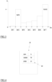
- Such first situation is exemplified in figure 5 with a graph of the intensity of the variation in magnetic field over time, where the peaks due to the sparking spark are indicated with PS.
- a second situation is the one in which a variation in magnetic field due to the rotation of the magnets of the free wheel is interposed between two variation peaks of the magnetic field due to the sparking spark.
- Such second situation is illustrated in figures 6 and 7 with a graph of the intensity of the variation in magnetic field over time, where the peaks due to the sparking spark are indicated with PS, and the peaks due to the rotation of the free wheel are indicated with PW.
- a third situation is the one in which two variations in magnetic field due to the rotation of the magnets of the free wheel are interposed between two variation peaks of the magnetic field due to the sparking spark.
- the measurement every six peaks allows having an optimum accuracy and simultaneously obtaining an energy saving because there is less consumption in recording six peaks each sampling period with respect to twelve or sixty peaks.
- the motor is always either at maximum speed or minimum speed and remains for such little time at intermediate speeds at which the aforesaid transitions occur, and the transition is so quick that such error is completely irrelevant in the computation of the overall hours of use.
- An aspect of the invention provides for the method to comprise the following steps:
- the step of measuring at least one predetermined overall number of time intervals may comprise the step of accelerating the endothermic motor of the tool at least once from the idling rotating speed to the maximum rotating speed.
- the invention also makes available an apparatus as defined in claim 4, for the deferred estimation of the time for which an endothermic motor of a tool has operated at predetermined rotating speeds, said apparatus comprising an acquisition device provided with:
- an apparatus is made available that is capable of accurately estimating the number of operating hours of the tool with which it is associated and that requires less frequent maintenance intervals than the battery of the acquisition device with respect to the case in which the data are processed by the acquisition device itself since the energy consumption due to the data processing is transferred to a remote device.
- the remote device may comprise a displaying device and the processing unit is configured to show a report on the displaying device showing, for each calculated representative rotation frequency value, the operating time associated therewith.
- An apparatus for estimating the time for which an endothermic motor of a tool has operated at predetermined rotating speeds is indicated as a whole with 1, i.e. at about predetermined rotating speeds, in particular at least at one between the minimum rotating speed and the maximum rotating speed.
- such estimate is differed, i.e. not in real time during the operation of the endothermic motor.
- Said tool is preferably a landscaping tool, such as for example a chainsaw, a blower (shown in the drawings with number 5), a brush cutter, a hedge cutter, a lawn trimmer or a motor hoe.
- a landscaping tool such as for example a chainsaw, a blower (shown in the drawings with number 5), a brush cutter, a hedge cutter, a lawn trimmer or a motor hoe.
- Such tools are all provided with an endothermic motor, for example of the two-stroke type, housed in a protective crankcase 10, for example made of plastic material.
- a protective crankcase may also make available a grasping portion of the tool, such as for example a handle.
- the engine works for almost the entire time either at a maximum rotation speed or at a minimum rotation speed.
- the apparatus 1 comprises an acquisition device 15 provided with a casing 20, for example a box-like casing, inside of which an inductive sensor 25 is housed that is capable of measuring variations in magnetic and/or electromagnetic field.
- a casing 20 for example a box-like casing, inside of which an inductive sensor 25 is housed that is capable of measuring variations in magnetic and/or electromagnetic field.
- Such inductive sensor comprises a spiral-wound electrically conductive wire and/or a coil made of electrically conductive material.
- said variations in electromagnetic field are mainly due to the passage of an electric current through a respective wire of the motor to generate the sparking spark in combustion chamber, and/or from the rotation of the free wheel of the motor.
- the acquisition device 15 comprises a storage unit that is directly housed in the casing 20.
- the storage unit comprises a volatile storage device 30, commonly known as RAM, and a non-volatile storage device 35.
- volatile storage device means a storage device that if it is not powered, loses the data stored therein, while a non-volatile storage device is designed so as to keep the data stored also if not powered.
- the acquisition device 15 also comprises a wireless transmitter housed in the casing 20, for example of the Bluetooth or WLAN type.
- the acquisition device 15 preferably also comprises a transceiver 40 housed in the casing 20, for example of the Bluetooth or WLAN type, so as to also receive external commands.
- the acquisition device 15 comprises an electronic control and command unit 45 operatively connected to the inductive sensor 25, the wireless transmitter, i.e. the wireless transceiver 40 and the storage unit, i.e. volatile storage 30 and non-volatile storage 35, it also housed in the casing 20.
- the wireless transmitter i.e. the wireless transceiver 40
- the storage unit i.e. volatile storage 30 and non-volatile storage 35
- the acquisition device 15, i.e. the components thereof, is powered by means of a source of electric energy, for example a battery 50, housed in the casing 20.
- a source of electric energy for example a battery 50, housed in the casing 20.
- the battery 50 is for example, a coin-type battery.
- the inductive sensor 25 is powered by the battery 50.
- the apparatus 1 also comprises a remote device 55 configured to wirelessly interface with the acquisition device 15.
- Said remote device 55 may comprise a wireless receiver and a processing unit 60 connected to the wireless receiver and configured to process the data acquired by the acquisition device.
- the remote device preferably comprises a wireless transceiver 65, for example of the Bluetooth or WLAN type, so as to both receive data from the acquisition device and send commands.
- the remote device 55 may for example, be a smartphone.
- the apparatus 1 may also comprise a further remote device 70 provided with a wireless transceiver 75 and a processing unit 80 configured to process the data acquired by the acquisition device.
- the remote device 55 is to comprise the wireless transceiver configured to transmit the data acquired by the acquisition device to the further remote device and the processing unit is configured only to transmit and receive the data of the acquisition device 15 and from the further remote device and it is not configured to process the data from the acquisition device.
- the further remote device may for example, be a computer connected to the remote device via the Internet.
- the remote device 55 comprises a displaying device 85, such as for example, an electronic display.
- the further remote device may comprise a displaying device in the form of an electronic display.
- the above-described apparatus 1 is configured to carry out a method for estimating the time for which an endothermic motor of a tool has operated at predetermined rotating speeds, i.e. at about predetermined rotating speeds, in particular at least at one between the minimum rotating speed and the maximum rotating speed.
- such estimate is differed, i.e. not in real time during the operation of the endothermic motor.
- such method comprises a sequence of steps relative to acquiring data and storing data, for example carried out by the electronic control and command unit 45 of the acquisition device 15, and a sequence of steps relative to processing data acquired, for example carried out by the processing unit 60 of the remote device 55 and/or by the processing unit 80 of the further remote device 70.
- the method may also comprise a successive step of displaying processed data, for example carried out by the remote device 55, i.e. by the displaying device 85 thereof.
- the inductive sensor 25 i.e. the acquisition device provided with the inductive sensor 25, within a predetermined distance from the endothermic motor of the tool so that the inductive sensor can pick up the magnetic field variations generated by the operation of the endothermic motor.
- a predetermined distance is less than 10 cm.
- the sequence of steps relative to acquiring and storing data comprises the step of cyclically measuring, at a pre-set sampling period ⁇ C, an overall time interval ⁇ T between a first and a last variation peak of the electromagnetic field, where the pre-set sampling period ⁇ C is greater than the overall time interval ⁇ T, i.e. than the maximum overall time interval measurable (see figure 7 ).
- the pre-set sampling period ⁇ C may be set equal to 250 ms in order to allow an optimal balancing between electric energy consumption and measurement accuracy.
- the step of cyclically measuring the overall time interval ⁇ T with sampling periods ⁇ C may be started manually by the operator by actuating the acquisition device by means of a suitable manual command or preferably, the actuation of such step may occur automatically based on the monitoring of eddy currents within the inductive sensor generated by the variations in electromagnetic field due to the operation of the endothermic motor. Reaching a predetermined variation value of the electromagnetic field, for example for a given period of time, actuates the beginning of the cyclical measuring.
- the first and the last peak are the start and tail ends of a sequence of peaks PS, PW having a predetermined number of successive peaks, i.e. immediately successive to one another.
- the number of peaks of the sequence is a positive, whole number that is at least equal to six and a least common multiple at least of two and three.
- the number of peaks is equal to six, therefore a least common multiple of two and three.
- peak PS, PW means a variation in the electromagnetic field having greater intensity at a predetermined threshold value.
- Such threshold value is greater than an intensity value of average magnetic field measured during the operation of the endothermic motor.
- a peak PS, PW can be identified as a variation in electromagnetic field that has an upward portion followed by a portion having substantially constant intensity, which in turn is followed by a downward portion.
- the step therefore provides sensing a decreasing gradient intensity of the electromagnetic field.
- the electronic control and command unit of the acquisition device is therefore configured to identify the decreasing gradients of variations in the electromagnetic field.
- the method provides, i.e. the electronic control and command unit is configured, to start the measuring of the overall time interval ⁇ T within a sampling period ⁇ C when it senses, in the manners described, a first peak, and successively to increase the value of a meter by one each time it senses a peak PS, PW.
- the meter reaches a number equal to the number of peaks of the sequence of peaks, it is provided to interrupt the measuring of the overall time interval while storing the datum and interrupting the measuring of the variations in electromagnetic field up to the start of a new sampling period ⁇ C.
- the method herein introduced provides only measuring the time interval between the first peak and the last peak of said sequence of peaks PS, PW, and does not provide measuring the intensity of the peaks or the time the peaks last. This allows a significant savings in electric energy.
- the sequence of steps relative to acquiring and storing data may comprise the step of storing, preferably in the volatile storage, the value of the overall time interval ⁇ T measured.
- the sequence of steps relative to acquiring and storing data comprises the step of obtaining, from the overall time interval measured, the respective frequency thereof.
- the frequency is calculated by dividing 1 by the overall time interval measured, which overall time interval is to have a value measured in seconds. In this manner, a frequency value in Hertz is obtained, i.e. s -1 .
- the method provides making available a plurality of pre-set ranges of frequencies RF1, RF2, RF3, RF4, RF5, RF6, RF7 of the overall time intervals ⁇ T measured.
- the method provides making available a plurality of meters, each one of which being associated with a pre-set range of frequencies overall time intervals.
- each range of frequencies has an amplitude of 5 Hertz, and overall the ranges start from 20 Hertz and end at 70 Hertz.
- the values of the pre-set ranges of frequencies RF1, RF2, RF3, RF4, RF5, RF6, RF7 are for example, stored in the non-volatile storage 35.
- the sequence of steps relative to acquiring and storing data comprises the step of increasing the number of occurrences of a corresponding range of frequencies RF1, RF2, RF3, RF4, RF5, RF6, RF7 of the overall time intervals ⁇ T by one each time an overall time interval having a frequency falling within the pre-set range of frequencies RF1, RF2, RF3, RF4, RF5, RF6, RF7 is measured.
- the electronic control and command unit may compare the frequency value of overall time intervals measured with the ranges of pre-set ranges of frequencies and to increase the occurrences by one when there is a correspondence between the value measured and the range stored in the memory.
- occurrence means the number of times that a given event is repeated over time. For example, if during the measuring period, the endothermic motor was sensed 100 times at a frequency of 30 Hertz, 100 times at a frequency of 31 Hertz, 100 times at a frequency of 32 Hertz, 100 times at a frequency of 33 Hertz and 100 times at a frequency of 34 Hertz, the number of the occurrences of a pre-set range of frequencies RF2 that goes from 30 to 34 Hertz therefore is 500 occurrences.
- Figure three illustrates a graph of the occurrences created by means of the method hereinto introduced, in which the occurrences are on the Y axis, indicated with N (the occurrences do not have a unit of measurement) and the frequencies (in Hertz) are on the X axis and the pre-set ranges of frequencies RF1, RF2, RF3, RF4, RF5, RF6, RF7 are shown.
- Such graph of the occurrences illustrates a part of the present method and could be created and displayed during the method for checking the correct functioning of the method. However, the creation and/or display of such graph of the occurrences is not required for the correct functioning of the method.
- the sequence of steps relative to acquiring and storing the data may comprise the step of storing the number of occurrences in a corresponding range of frequencies in the volatile storage up to reaching a predefined maximum value, which when reached, the number of occurrences is stored in the non-volatile storage. It may also be provided that the number of occurrences stored in the non-volatile storage during such transfer from one storage to the other is one for each maximum value of occurrences reached in the volatile storage.
- an option of calibrating such step may provide setting the predefined maximum value at 240 so that reaching such maximum value corresponds to one operating minute of the motor within a pre-set range of frequencies, given that the sampling period is equal to 250 ms.
- the method may also provide, in the case in which after sensing the activity of the endothermic motor it senses a non-use of the endothermic motor, for it to store the data measured in the non-volatile storage also in the case in which the predefined maximum value of occurrences was not reached.
- the sequence of steps relative to acquiring and storing data concludes with storing the occurrences of the pre-set ranges of frequencies. Therefore, the operations carried out by the acquisition device 15 are concluded.
- this step concludes after measuring at least one predetermined overall number of time intervals ⁇ T.
- the method provides the step of transferring the values of occurrences of the pre-set ranges of frequencies from the acquisition device 15 to the remote device 55, which may in turn for example, send them to the further remote device 70.
- the transfer of the data measured and stored may be carried out automatically, for example by nearing the remote device to the acquisition device until the respective transceiver means 40, 65 establish a communication between the two devices.
- the sequence of steps relative to processing the data acquired starts with the step of comparing the number of occurrences of each pre-set range of frequencies RF1, RF2, RF3, RF4, RF5, RF6, RF7 of overall time intervals measured and of identifying the two with the largest number of occurrences, labelling between the two the pre-set range of frequencies having lowest, i.e. lower, frequencies as indicative of the range of rotation frequencies of the minimum speed and the other, i.e. having highest frequencies between the two, as indicative of the range of rotation frequency of the maximum speed.
- pre-set range of frequencies having the largest number of occurrences and having less frequencies with respect to a pre-set frequency value indicative of an intermediate rotating speed and indicating it as indicative of the range of rotation frequencies of the minimum speed it is provided to select the pre-set range of frequencies having the largest number of occurrences and having less frequencies with respect to a pre-set frequency value indicative of an intermediate rotating speed and indicating it as indicative of the range of rotation frequencies of the minimum speed.
- such two ranges are indicated in figure three respectively as MIN, the pre-set range of frequencies RF2, which goes from 30 to 35 Hertz, and MAX, the pre-set range of frequencies RF7, which goes from 55 to 60 Hertz.
- an overall threshold frequency is calculated by calculating an arithmetic average between at least one frequency of the range of the minimum speed and one frequency of the range of the maximum speed. For example, to calculate such overall threshold frequency, it is possible to take the lowest end of the pre-set range of frequencies indicative of the rotation of the motor at the minimum speed, and the highest end of the pre-set range of frequencies indicative of the rotation of the motor at the maximum speed.
- a plurality of corrective coefficients can be determined by dividing the number of peaks of the sequence of peaks respectively by one, and for each of the whole and positive numbers of which the number of peaks is a least common multiple.
- a first corrective coefficient is obtained by dividing the number of peaks of the sequence of peaks by one
- a second corrective coefficient is obtained by dividing the number of peaks by a positive whole number of which the number of peaks is a least common multiple
- a third corrective coefficient is obtained by dividing the number of peaks by another positive whole number of which the number of peaks is a least common multiple, and so on.
- the corrective factor of six is to be applied to a situation in which out of six peaks, each peak measured of the sequence of peaks is due to a variation in magnetic field caused by the sparking spark
- the corrective factor of three is to be applied to a situation in which out of six peaks, only three are due to a variation in magnetic field caused by the sparking spark because one variation in electromagnetic field of another nature, in particular due to the rotation of the free wheel, is interposed every two variations in electromagnetic field due to the sparking spark.
- the corrective factor of two is to be applied to a situation in which out of six peaks, two are due to a variation in magnetic field caused by the sparking spark because two variations in electromagnetic field of another nature are interposed every two variations in electromagnetic field due to the sparking spark.
- the sequence of steps relative to processing the data acquired continues with calculating a plurality of rotation frequencies by multiplying, for each corrective coefficient of the plurality of corrective coefficients, a frequency value of the range of frequencies of the minimum speed, preferably the lowest end of the frequency range of the minimum speed.
- the values of the calculated rotation frequencies are compared with a (pre-set) reference range of frequencies indicative of the idling of the endothermic motor.
- a (pre-set) reference range of frequencies indicative of the idling of the endothermic motor comprises the frequencies corresponding to the operation of the motor between a minimum of 2200 rpm and a maximum of 4000 rpm.
- Such reference range of frequencies indicative of the idling may for example, be stored in a non-volatile storage of the remote device or of the further remote device.
- the sequence of steps relative to processing the data acquired continues with storing the corrective coefficient of the plurality of corrective coefficients corresponding to the rotation frequency falling within the reference range of frequencies indicative of the idling of the endothermic motor, as a corrective coefficient of the low speeds, and calculating a representative rotation frequency for each pre-set range of frequencies lower than the threshold frequency, multiplying a frequency value of each range by the corrective coefficient of the low speeds.
- the frequency value of each pre-set range of frequencies to be multiplied by the corrective coefficient of the low speeds is the lowest end of said range.
- the calculated representative rotation frequencies are stored, for example in the non-volatile storage of the remote device or of the further remote device, according to which of the two processes the data.
- the sequence of steps relative to processing the data acquired continues with calculating a plurality of rotation frequencies by multiplying, for each corrective coefficient of the plurality of corrective coefficients, a frequency value of the range of frequencies of the maximum speed, preferably the highest end of the frequency range of the maximum speed.
- the method may provide making available a database of a plurality of types of tools provided with endothermic motors, comprising for example the ones listed above, in which each type of tool is associated with a predefined reference range of frequencies indicative of the maximum running of the endothermic motor of said type of tool.
- the method may provide for such foresight to be present also for the reference frequency values of the minimum speed.
- Such reference range of frequencies indicative of the maximum running may for example, be stored in a non-volatile storage of the remote device or of the further remote device.
- the sequence of steps relative to processing the data acquired continues with storing the corrective coefficient of the plurality of corrective coefficients corresponding to the rotation frequency falling within the reference range of frequencies indicative of the maximum running of the endothermic motor as a corrective coefficient of the high speeds, and calculating a representative rotation frequency for each pre-set range of frequencies higher than the threshold frequency, multiplying a frequency value of each pre-set range of frequencies by the corrective coefficient of the high speeds.
- the frequency value of each pre-set range of frequencies to be multiplied by the corrective coefficient of the high speeds is the highest end of the range.
- the calculated representative rotation frequencies are stored, preferably in the non-volatile storage of the remote device or of the further remote device.
- the operating time in which the motor has operated at the rotation frequencies of each pre-set range of frequencies is determined by multiplying the number of occurrences of each range of frequencies by the value of the pre-set sampling period ⁇ C, and associating, in the sense of connecting until there is a bi-unique connection, the operating times calculated at the corresponding pre-set ranges of frequencies.
- the calculation is made on the occurrences stored in the non-volatile storage, therefore the number of the occurrences is already representative of the operating minutes of the motor.
- the method may provide transforming the value of the calculated representative rotation frequencies into revolutions per minute, i.e. rpm.
- Such transformation of measurement unit occurs by multiplying the value of the frequencies in Hertz by 60.
- the method may also provide the step of displaying, on the displaying device 85, such as for example illustrated in figure four, a report indicating, for each calculated representative rotation frequency value, preferably displayed in revolutions per minute, the operating time associated therewith.
- the method may provide comparing the operating time values associated with pre-selected values of representative rotation frequencies with predetermined threshold values of the operating time at a given rotating speed and generating an alarm signal if such threshold value is exceeded. For example, the method may provide comparing the operating time value of the representative frequency value corresponding to the pre-set range of frequencies of the maximum speed with a pre-set threshold value of the operating time of the motor at maximum speed.
- the whole method up to the part of associating the operating time with the predetermined rotating speeds to be carried out by the acquisition device alone.
- the remote device only carries out the step of displaying the data obtained, i.e. of creating a report of such data.
- Such embodiment would lose the advantage of the reduced consumption of the battery of the acquisition device 15 when not assigned to processing data and would also lose the advantage of a particularly simple, therefore robust and affordable, acquisition device, however it would in any case allow obtaining the advantages associated with the features of claim one.
- the operation of the apparatus of the method according to the invention is as follows.
- the user installs the acquisition device 15 on the protective crankcase 10 of the tool, for example by fastening it by means of an adhesive or non-removable connection members or removable connection members.
- the acquisition device stores the data that will be obsessively processed by the remote device 55 or by the further remote device 70.
- the user may near the remote device 55 to the acquisition device 15 so that a wireless communication is established between the two such as to allow the transfer of the data acquired to the remote device.
- the data acquired may be processed directly by the remote device or sent for processing to the further remote device.
- the data acquired are stored simultaneously in the remote device 55 until it is possible to establish a connection between the remote device and the further remote device.
- the data Once the data have been processed to obtain the operating times at representative rotating speeds, such data are displayed in the displaying device, for example in the form of a report as in figure 4 .
- the invention thus conceived is susceptible to many modifications and variants, all falling within the same inventive concept, whereby the scope of the invention is defined by the appended claims. In practice, any materials and also any contingent shapes and sizes may be used, depending on the needs, without departing from the scope of protection of the following claims.
Landscapes
- Physics & Mathematics (AREA)
- General Physics & Mathematics (AREA)
- Chemical & Material Sciences (AREA)
- Engineering & Computer Science (AREA)
- Combustion & Propulsion (AREA)
- Control Of Electric Motors In General (AREA)
- Combined Controls Of Internal Combustion Engines (AREA)
Applications Claiming Priority (2)
| Application Number | Priority Date | Filing Date | Title |
|---|---|---|---|
| IT102020000011872A IT202000011872A1 (it) | 2020-05-21 | 2020-05-21 | Metodo per la stima, mediante misurazioni effettuate tramite un sensore induttivo, del tempo per il quale un motore endotermico di un attrezzo ha operato a predeterminati regimi di rotazione, ed apparato per l’implementazione di tale metodo |
| PCT/IB2021/053775 WO2021234489A1 (en) | 2020-05-21 | 2021-05-05 | Method for estimating, by means of measurements with an inductive sensor, the time for which an endothermic motor has operated at the predetermined speeds, and apparatus for implementing such method |
Publications (2)
| Publication Number | Publication Date |
|---|---|
| EP4154017A1 EP4154017A1 (en) | 2023-03-29 |
| EP4154017B1 true EP4154017B1 (en) | 2024-03-27 |
Family
ID=71784589
Family Applications (1)
| Application Number | Title | Priority Date | Filing Date |
|---|---|---|---|
| EP21723415.2A Active EP4154017B1 (en) | 2020-05-21 | 2021-05-05 | Method for estimating, by means of measurements with an inductive sensor, the time for which an endothermic motor has operated at the predetermined speeds, and apparatus for implementing such method |
Country Status (7)
| Country | Link |
|---|---|
| US (1) | US12209887B2 (pl) |
| EP (1) | EP4154017B1 (pl) |
| CN (1) | CN115552252B (pl) |
| ES (1) | ES2983182T3 (pl) |
| IT (1) | IT202000011872A1 (pl) |
| PL (1) | PL4154017T3 (pl) |
| WO (1) | WO2021234489A1 (pl) |
Family Cites Families (11)
| Publication number | Priority date | Publication date | Assignee | Title |
|---|---|---|---|---|
| JPS5860212A (ja) * | 1982-02-15 | 1983-04-09 | Mitsubishi Motors Corp | 運行管理装置 |
| CA1247743A (en) * | 1985-01-24 | 1988-12-28 | Izuru Morita | Operation data recording system |
| US5043659A (en) * | 1989-12-18 | 1991-08-27 | Clean Air Technologies Inc. | Non-intrusive tachometer for spark ignition autos |
| DE69706581T2 (de) * | 1996-02-29 | 2002-07-11 | Kelsey-Hayes Co., Livonia | Positionsgeberschaltung für einen elektrischen Motor |
| FI20000646A0 (fi) * | 2000-03-20 | 2000-03-20 | Abb Research Ltd | Menetelmä pyörimisnopeuden määrittämiseksi |
| SE532224C2 (sv) * | 2008-02-15 | 2009-11-17 | Atlas Copco Tools Ab | Pneumatiskt kraftverktyg försett med indikeringsorgan för arbetsparametervärden |
| US9192096B2 (en) * | 2012-08-31 | 2015-11-24 | Deere & Company | Electric lawn tractor power management system and method |
| CN107291071A (zh) * | 2016-03-30 | 2017-10-24 | 苏州宝时得电动工具有限公司 | 自动工作系统、自动行走设备及其转向方法 |
| CN108802616A (zh) * | 2017-04-27 | 2018-11-13 | 苏州宝时得电动工具有限公司 | 电动设备及其电池电量管理方法和系统 |
| DE202017103056U1 (de) * | 2017-05-19 | 2018-08-26 | Wilhelm Altendorf Gmbh & Co. Kg | Verschleißermittlung bei Sägewerkzeugen |
| CN109861172B (zh) * | 2019-03-29 | 2020-07-03 | 北京经纬恒润科技有限公司 | 电机过热保护方法及装置 |
-
2020
- 2020-05-21 IT IT102020000011872A patent/IT202000011872A1/it unknown
-
2021
- 2021-05-05 ES ES21723415T patent/ES2983182T3/es active Active
- 2021-05-05 WO PCT/IB2021/053775 patent/WO2021234489A1/en not_active Ceased
- 2021-05-05 PL PL21723415.2T patent/PL4154017T3/pl unknown
- 2021-05-05 EP EP21723415.2A patent/EP4154017B1/en active Active
- 2021-05-05 CN CN202180033986.0A patent/CN115552252B/zh active Active
- 2021-05-05 US US17/926,544 patent/US12209887B2/en active Active
Also Published As
| Publication number | Publication date |
|---|---|
| EP4154017A1 (en) | 2023-03-29 |
| IT202000011872A1 (it) | 2021-11-21 |
| CN115552252B (zh) | 2025-10-28 |
| WO2021234489A1 (en) | 2021-11-25 |
| US20230204390A1 (en) | 2023-06-29 |
| US12209887B2 (en) | 2025-01-28 |
| ES2983182T3 (es) | 2024-10-22 |
| CN115552252A (zh) | 2022-12-30 |
| PL4154017T3 (pl) | 2024-07-29 |
Similar Documents
| Publication | Publication Date | Title |
|---|---|---|
| US4525782A (en) | Process for determining maintenance and serving intervals on motor vehicles | |
| CN100481137C (zh) | 评价机器的条件的方法和系统以及便携式分析仪 | |
| EP1604783B1 (en) | System for assisting selection of power tool | |
| US6973377B2 (en) | Automotive performance meter | |
| AU2003288666B2 (en) | Device and method of monitoring the starting capability of a vehicle's starter battery | |
| US6972668B2 (en) | Tamper-evident use-indicating odometer and engine-timer | |
| US20220176527A1 (en) | Method for Detecting a First Operating State of a Handheld Power Tool | |
| US4106095A (en) | Electrical usage display system | |
| US6124692A (en) | Method and apparatus for reducing electrical power consumption in a machine monitor | |
| US10596652B2 (en) | Systems and methods for fuel level monitoring in an engine-driven generator | |
| EP0701134A1 (en) | Tachometer based on electrical ripple and calibrated by mechanical engine signals | |
| US7047125B1 (en) | Internal combustion engine performance calibration systems | |
| US10974399B2 (en) | Method for determining the time behavior of a cyclic motor process during use of an electrical hair removal device and hair removal device | |
| EP4154017B1 (en) | Method for estimating, by means of measurements with an inductive sensor, the time for which an endothermic motor has operated at the predetermined speeds, and apparatus for implementing such method | |
| US4358828A (en) | Engine speed measuring system | |
| KR20220041852A (ko) | 휴대용 전동 공구의 작업 진행 상황을 감지하는 방법 | |
| JP2020518467A (ja) | 少なくとも1つの工具の少なくとも1つの特性値を検出するための方法、追加モジュール、及び、工具 | |
| CN114649565A (zh) | 一种锂电池化成分容设备的控制方法及系统 | |
| CN109190220B (zh) | 一种基于小波分析的发动机气密性诊断方法以及系统 | |
| US7726181B2 (en) | Ignition timing measuring and display device of internal combustion engine | |
| KR100780920B1 (ko) | 차량 연비 측정장치 및 그 측정 방법 | |
| WO2006136503A1 (en) | Control and diagnostic unit for pneumatic tool | |
| EP3985244B1 (en) | Ignition coil unit collecting operating data | |
| US6671639B2 (en) | Method of determining speed of rotation of squirrel-cage motor and a computer software product to carry out the method | |
| JP7509416B2 (ja) | 肉厚測定システム、肉厚測定方法及び肉厚測定プログラム |
Legal Events
| Date | Code | Title | Description |
|---|---|---|---|
| STAA | Information on the status of an ep patent application or granted ep patent |
Free format text: STATUS: UNKNOWN |
|
| STAA | Information on the status of an ep patent application or granted ep patent |
Free format text: STATUS: THE INTERNATIONAL PUBLICATION HAS BEEN MADE |
|
| PUAI | Public reference made under article 153(3) epc to a published international application that has entered the european phase |
Free format text: ORIGINAL CODE: 0009012 |
|
| STAA | Information on the status of an ep patent application or granted ep patent |
Free format text: STATUS: REQUEST FOR EXAMINATION WAS MADE |
|
| 17P | Request for examination filed |
Effective date: 20221014 |
|
| AK | Designated contracting states |
Kind code of ref document: A1 Designated state(s): AL AT BE BG CH CY CZ DE DK EE ES FI FR GB GR HR HU IE IS IT LI LT LU LV MC MK MT NL NO PL PT RO RS SE SI SK SM TR |
|
| P01 | Opt-out of the competence of the unified patent court (upc) registered |
Effective date: 20230605 |
|
| DAV | Request for validation of the european patent (deleted) | ||
| DAX | Request for extension of the european patent (deleted) | ||
| GRAP | Despatch of communication of intention to grant a patent |
Free format text: ORIGINAL CODE: EPIDOSNIGR1 |
|
| STAA | Information on the status of an ep patent application or granted ep patent |
Free format text: STATUS: GRANT OF PATENT IS INTENDED |
|
| INTG | Intention to grant announced |
Effective date: 20231207 |
|
| RIC1 | Information provided on ipc code assigned before grant |
Ipc: G07C 5/04 20060101ALI20231127BHEP Ipc: G07C 3/00 20060101ALI20231127BHEP Ipc: G01P 21/02 20060101ALI20231127BHEP Ipc: G01P 3/48 20060101AFI20231127BHEP |
|
| GRAS | Grant fee paid |
Free format text: ORIGINAL CODE: EPIDOSNIGR3 |
|
| GRAA | (expected) grant |
Free format text: ORIGINAL CODE: 0009210 |
|
| STAA | Information on the status of an ep patent application or granted ep patent |
Free format text: STATUS: THE PATENT HAS BEEN GRANTED |
|
| AK | Designated contracting states |
Kind code of ref document: B1 Designated state(s): AL AT BE BG CH CY CZ DE DK EE ES FI FR GB GR HR HU IE IS IT LI LT LU LV MC MK MT NL NO PL PT RO RS SE SI SK SM TR |
|
| REG | Reference to a national code |
Ref country code: GB Ref legal event code: FG4D |
|
| REG | Reference to a national code |
Ref country code: CH Ref legal event code: EP |
|
| REG | Reference to a national code |
Ref country code: DE Ref legal event code: R096 Ref document number: 602021010993 Country of ref document: DE |
|
| REG | Reference to a national code |
Ref country code: IE Ref legal event code: FG4D |
|
| PG25 | Lapsed in a contracting state [announced via postgrant information from national office to epo] |
Ref country code: LT Free format text: LAPSE BECAUSE OF FAILURE TO SUBMIT A TRANSLATION OF THE DESCRIPTION OR TO PAY THE FEE WITHIN THE PRESCRIBED TIME-LIMIT Effective date: 20240327 |
|
| REG | Reference to a national code |
Ref country code: LT Ref legal event code: MG9D |
|
| PG25 | Lapsed in a contracting state [announced via postgrant information from national office to epo] |
Ref country code: GR Free format text: LAPSE BECAUSE OF FAILURE TO SUBMIT A TRANSLATION OF THE DESCRIPTION OR TO PAY THE FEE WITHIN THE PRESCRIBED TIME-LIMIT Effective date: 20240628 |
|
| PG25 | Lapsed in a contracting state [announced via postgrant information from national office to epo] |
Ref country code: HR Free format text: LAPSE BECAUSE OF FAILURE TO SUBMIT A TRANSLATION OF THE DESCRIPTION OR TO PAY THE FEE WITHIN THE PRESCRIBED TIME-LIMIT Effective date: 20240327 Ref country code: RS Free format text: LAPSE BECAUSE OF FAILURE TO SUBMIT A TRANSLATION OF THE DESCRIPTION OR TO PAY THE FEE WITHIN THE PRESCRIBED TIME-LIMIT Effective date: 20240627 |
|
| PG25 | Lapsed in a contracting state [announced via postgrant information from national office to epo] |
Ref country code: RS Free format text: LAPSE BECAUSE OF FAILURE TO SUBMIT A TRANSLATION OF THE DESCRIPTION OR TO PAY THE FEE WITHIN THE PRESCRIBED TIME-LIMIT Effective date: 20240627 Ref country code: NO Free format text: LAPSE BECAUSE OF FAILURE TO SUBMIT A TRANSLATION OF THE DESCRIPTION OR TO PAY THE FEE WITHIN THE PRESCRIBED TIME-LIMIT Effective date: 20240627 Ref country code: LT Free format text: LAPSE BECAUSE OF FAILURE TO SUBMIT A TRANSLATION OF THE DESCRIPTION OR TO PAY THE FEE WITHIN THE PRESCRIBED TIME-LIMIT Effective date: 20240327 Ref country code: HR Free format text: LAPSE BECAUSE OF FAILURE TO SUBMIT A TRANSLATION OF THE DESCRIPTION OR TO PAY THE FEE WITHIN THE PRESCRIBED TIME-LIMIT Effective date: 20240327 Ref country code: GR Free format text: LAPSE BECAUSE OF FAILURE TO SUBMIT A TRANSLATION OF THE DESCRIPTION OR TO PAY THE FEE WITHIN THE PRESCRIBED TIME-LIMIT Effective date: 20240628 Ref country code: FI Free format text: LAPSE BECAUSE OF FAILURE TO SUBMIT A TRANSLATION OF THE DESCRIPTION OR TO PAY THE FEE WITHIN THE PRESCRIBED TIME-LIMIT Effective date: 20240327 Ref country code: BG Free format text: LAPSE BECAUSE OF FAILURE TO SUBMIT A TRANSLATION OF THE DESCRIPTION OR TO PAY THE FEE WITHIN THE PRESCRIBED TIME-LIMIT Effective date: 20240327 |
|
| REG | Reference to a national code |
Ref country code: NL Ref legal event code: MP Effective date: 20240327 |
|
| PG25 | Lapsed in a contracting state [announced via postgrant information from national office to epo] |
Ref country code: SE Free format text: LAPSE BECAUSE OF FAILURE TO SUBMIT A TRANSLATION OF THE DESCRIPTION OR TO PAY THE FEE WITHIN THE PRESCRIBED TIME-LIMIT Effective date: 20240327 Ref country code: LV Free format text: LAPSE BECAUSE OF FAILURE TO SUBMIT A TRANSLATION OF THE DESCRIPTION OR TO PAY THE FEE WITHIN THE PRESCRIBED TIME-LIMIT Effective date: 20240327 |
|
| PG25 | Lapsed in a contracting state [announced via postgrant information from national office to epo] |
Ref country code: NL Free format text: LAPSE BECAUSE OF FAILURE TO SUBMIT A TRANSLATION OF THE DESCRIPTION OR TO PAY THE FEE WITHIN THE PRESCRIBED TIME-LIMIT Effective date: 20240327 |
|
| REG | Reference to a national code |
Ref country code: AT Ref legal event code: MK05 Ref document number: 1670396 Country of ref document: AT Kind code of ref document: T Effective date: 20240327 |
|
| PG25 | Lapsed in a contracting state [announced via postgrant information from national office to epo] |
Ref country code: NL Free format text: LAPSE BECAUSE OF FAILURE TO SUBMIT A TRANSLATION OF THE DESCRIPTION OR TO PAY THE FEE WITHIN THE PRESCRIBED TIME-LIMIT Effective date: 20240327 |
|
| PG25 | Lapsed in a contracting state [announced via postgrant information from national office to epo] |
Ref country code: IS Free format text: LAPSE BECAUSE OF FAILURE TO SUBMIT A TRANSLATION OF THE DESCRIPTION OR TO PAY THE FEE WITHIN THE PRESCRIBED TIME-LIMIT Effective date: 20240727 |
|
| PG25 | Lapsed in a contracting state [announced via postgrant information from national office to epo] |
Ref country code: PT Free format text: LAPSE BECAUSE OF FAILURE TO SUBMIT A TRANSLATION OF THE DESCRIPTION OR TO PAY THE FEE WITHIN THE PRESCRIBED TIME-LIMIT Effective date: 20240729 Ref country code: SM Free format text: LAPSE BECAUSE OF FAILURE TO SUBMIT A TRANSLATION OF THE DESCRIPTION OR TO PAY THE FEE WITHIN THE PRESCRIBED TIME-LIMIT Effective date: 20240327 |
|
| REG | Reference to a national code |
Ref country code: ES Ref legal event code: FG2A Ref document number: 2983182 Country of ref document: ES Kind code of ref document: T3 Effective date: 20241022 |
|
| PG25 | Lapsed in a contracting state [announced via postgrant information from national office to epo] |
Ref country code: CZ Free format text: LAPSE BECAUSE OF FAILURE TO SUBMIT A TRANSLATION OF THE DESCRIPTION OR TO PAY THE FEE WITHIN THE PRESCRIBED TIME-LIMIT Effective date: 20240327 Ref country code: EE Free format text: LAPSE BECAUSE OF FAILURE TO SUBMIT A TRANSLATION OF THE DESCRIPTION OR TO PAY THE FEE WITHIN THE PRESCRIBED TIME-LIMIT Effective date: 20240327 |
|
| PG25 | Lapsed in a contracting state [announced via postgrant information from national office to epo] |
Ref country code: AT Free format text: LAPSE BECAUSE OF FAILURE TO SUBMIT A TRANSLATION OF THE DESCRIPTION OR TO PAY THE FEE WITHIN THE PRESCRIBED TIME-LIMIT Effective date: 20240327 |
|
| PG25 | Lapsed in a contracting state [announced via postgrant information from national office to epo] |
Ref country code: SK Free format text: LAPSE BECAUSE OF FAILURE TO SUBMIT A TRANSLATION OF THE DESCRIPTION OR TO PAY THE FEE WITHIN THE PRESCRIBED TIME-LIMIT Effective date: 20240327 |
|
| PG25 | Lapsed in a contracting state [announced via postgrant information from national office to epo] |
Ref country code: SM Free format text: LAPSE BECAUSE OF FAILURE TO SUBMIT A TRANSLATION OF THE DESCRIPTION OR TO PAY THE FEE WITHIN THE PRESCRIBED TIME-LIMIT Effective date: 20240327 Ref country code: SK Free format text: LAPSE BECAUSE OF FAILURE TO SUBMIT A TRANSLATION OF THE DESCRIPTION OR TO PAY THE FEE WITHIN THE PRESCRIBED TIME-LIMIT Effective date: 20240327 Ref country code: RO Free format text: LAPSE BECAUSE OF FAILURE TO SUBMIT A TRANSLATION OF THE DESCRIPTION OR TO PAY THE FEE WITHIN THE PRESCRIBED TIME-LIMIT Effective date: 20240327 Ref country code: PT Free format text: LAPSE BECAUSE OF FAILURE TO SUBMIT A TRANSLATION OF THE DESCRIPTION OR TO PAY THE FEE WITHIN THE PRESCRIBED TIME-LIMIT Effective date: 20240729 Ref country code: IS Free format text: LAPSE BECAUSE OF FAILURE TO SUBMIT A TRANSLATION OF THE DESCRIPTION OR TO PAY THE FEE WITHIN THE PRESCRIBED TIME-LIMIT Effective date: 20240727 Ref country code: EE Free format text: LAPSE BECAUSE OF FAILURE TO SUBMIT A TRANSLATION OF THE DESCRIPTION OR TO PAY THE FEE WITHIN THE PRESCRIBED TIME-LIMIT Effective date: 20240327 Ref country code: CZ Free format text: LAPSE BECAUSE OF FAILURE TO SUBMIT A TRANSLATION OF THE DESCRIPTION OR TO PAY THE FEE WITHIN THE PRESCRIBED TIME-LIMIT Effective date: 20240327 Ref country code: AT Free format text: LAPSE BECAUSE OF FAILURE TO SUBMIT A TRANSLATION OF THE DESCRIPTION OR TO PAY THE FEE WITHIN THE PRESCRIBED TIME-LIMIT Effective date: 20240327 |
|
| REG | Reference to a national code |
Ref country code: CH Ref legal event code: PL |
|
| REG | Reference to a national code |
Ref country code: DE Ref legal event code: R097 Ref document number: 602021010993 Country of ref document: DE |
|
| PG25 | Lapsed in a contracting state [announced via postgrant information from national office to epo] |
Ref country code: MC Free format text: LAPSE BECAUSE OF FAILURE TO SUBMIT A TRANSLATION OF THE DESCRIPTION OR TO PAY THE FEE WITHIN THE PRESCRIBED TIME-LIMIT Effective date: 20240327 |
|
| PG25 | Lapsed in a contracting state [announced via postgrant information from national office to epo] |
Ref country code: DK Free format text: LAPSE BECAUSE OF FAILURE TO SUBMIT A TRANSLATION OF THE DESCRIPTION OR TO PAY THE FEE WITHIN THE PRESCRIBED TIME-LIMIT Effective date: 20240327 |
|
| PG25 | Lapsed in a contracting state [announced via postgrant information from national office to epo] |
Ref country code: LU Free format text: LAPSE BECAUSE OF NON-PAYMENT OF DUE FEES Effective date: 20240505 |
|
| PG25 | Lapsed in a contracting state [announced via postgrant information from national office to epo] |
Ref country code: MC Free format text: LAPSE BECAUSE OF FAILURE TO SUBMIT A TRANSLATION OF THE DESCRIPTION OR TO PAY THE FEE WITHIN THE PRESCRIBED TIME-LIMIT Effective date: 20240327 Ref country code: LU Free format text: LAPSE BECAUSE OF NON-PAYMENT OF DUE FEES Effective date: 20240505 Ref country code: DK Free format text: LAPSE BECAUSE OF FAILURE TO SUBMIT A TRANSLATION OF THE DESCRIPTION OR TO PAY THE FEE WITHIN THE PRESCRIBED TIME-LIMIT Effective date: 20240327 Ref country code: CH Free format text: LAPSE BECAUSE OF NON-PAYMENT OF DUE FEES Effective date: 20240531 |
|
| PLBE | No opposition filed within time limit |
Free format text: ORIGINAL CODE: 0009261 |
|
| STAA | Information on the status of an ep patent application or granted ep patent |
Free format text: STATUS: NO OPPOSITION FILED WITHIN TIME LIMIT |
|
| REG | Reference to a national code |
Ref country code: BE Ref legal event code: MM Effective date: 20240531 |
|
| 26N | No opposition filed |
Effective date: 20250103 |
|
| PG25 | Lapsed in a contracting state [announced via postgrant information from national office to epo] |
Ref country code: IE Free format text: LAPSE BECAUSE OF NON-PAYMENT OF DUE FEES Effective date: 20240505 |
|
| PG25 | Lapsed in a contracting state [announced via postgrant information from national office to epo] |
Ref country code: BE Free format text: LAPSE BECAUSE OF NON-PAYMENT OF DUE FEES Effective date: 20240531 Ref country code: SI Free format text: LAPSE BECAUSE OF FAILURE TO SUBMIT A TRANSLATION OF THE DESCRIPTION OR TO PAY THE FEE WITHIN THE PRESCRIBED TIME-LIMIT Effective date: 20240327 |
|
| PGFP | Annual fee paid to national office [announced via postgrant information from national office to epo] |
Ref country code: PL Payment date: 20250418 Year of fee payment: 5 Ref country code: DE Payment date: 20250529 Year of fee payment: 5 |
|
| PGFP | Annual fee paid to national office [announced via postgrant information from national office to epo] |
Ref country code: GB Payment date: 20250527 Year of fee payment: 5 Ref country code: ES Payment date: 20250602 Year of fee payment: 5 |
|
| PGFP | Annual fee paid to national office [announced via postgrant information from national office to epo] |
Ref country code: IT Payment date: 20250326 Year of fee payment: 5 |
|
| PGFP | Annual fee paid to national office [announced via postgrant information from national office to epo] |
Ref country code: FR Payment date: 20250526 Year of fee payment: 5 |
|
| PGFP | Annual fee paid to national office [announced via postgrant information from national office to epo] |
Ref country code: TR Payment date: 20250428 Year of fee payment: 5 |
|
| PG25 | Lapsed in a contracting state [announced via postgrant information from national office to epo] |
Ref country code: CY Free format text: LAPSE BECAUSE OF FAILURE TO SUBMIT A TRANSLATION OF THE DESCRIPTION OR TO PAY THE FEE WITHIN THE PRESCRIBED TIME-LIMIT; INVALID AB INITIO Effective date: 20210505 |
|
| PG25 | Lapsed in a contracting state [announced via postgrant information from national office to epo] |
Ref country code: HU Free format text: LAPSE BECAUSE OF FAILURE TO SUBMIT A TRANSLATION OF THE DESCRIPTION OR TO PAY THE FEE WITHIN THE PRESCRIBED TIME-LIMIT; INVALID AB INITIO Effective date: 20210505 |