EP4153828B1 - Drehriegel mit federführung - Google Patents
Drehriegel mit federführung Download PDFInfo
- Publication number
- EP4153828B1 EP4153828B1 EP21732744.4A EP21732744A EP4153828B1 EP 4153828 B1 EP4153828 B1 EP 4153828B1 EP 21732744 A EP21732744 A EP 21732744A EP 4153828 B1 EP4153828 B1 EP 4153828B1
- Authority
- EP
- European Patent Office
- Prior art keywords
- pawl
- latch
- spring
- trigger
- striker
- Prior art date
- Legal status (The legal status is an assumption and is not a legal conclusion. Google has not performed a legal analysis and makes no representation as to the accuracy of the status listed.)
- Active
Links
Images












Classifications
-
- E—FIXED CONSTRUCTIONS
- E05—LOCKS; KEYS; WINDOW OR DOOR FITTINGS; SAFES
- E05B—LOCKS; ACCESSORIES THEREFOR; HANDCUFFS
- E05B15/00—Other details of locks; Parts for engagement by bolts of fastening devices
-
- E—FIXED CONSTRUCTIONS
- E05—LOCKS; KEYS; WINDOW OR DOOR FITTINGS; SAFES
- E05B—LOCKS; ACCESSORIES THEREFOR; HANDCUFFS
- E05B15/00—Other details of locks; Parts for engagement by bolts of fastening devices
- E05B15/0053—Other details of locks; Parts for engagement by bolts of fastening devices means providing a stable, i.e. indexed, position of lock parts
-
- E—FIXED CONSTRUCTIONS
- E05—LOCKS; KEYS; WINDOW OR DOOR FITTINGS; SAFES
- E05B—LOCKS; ACCESSORIES THEREFOR; HANDCUFFS
- E05B15/00—Other details of locks; Parts for engagement by bolts of fastening devices
- E05B15/02—Striking-plates; Keepers; Bolt staples; Escutcheons
-
- E—FIXED CONSTRUCTIONS
- E05—LOCKS; KEYS; WINDOW OR DOOR FITTINGS; SAFES
- E05B—LOCKS; ACCESSORIES THEREFOR; HANDCUFFS
- E05B15/00—Other details of locks; Parts for engagement by bolts of fastening devices
- E05B15/02—Striking-plates; Keepers; Bolt staples; Escutcheons
- E05B15/0205—Striking-plates, keepers, staples
- E05B15/0295—Striking-plates, keepers, staples specially adapted for forked or bifurcated bolts
-
- E—FIXED CONSTRUCTIONS
- E05—LOCKS; KEYS; WINDOW OR DOOR FITTINGS; SAFES
- E05B—LOCKS; ACCESSORIES THEREFOR; HANDCUFFS
- E05B15/00—Other details of locks; Parts for engagement by bolts of fastening devices
- E05B15/04—Spring arrangements in locks
-
- E—FIXED CONSTRUCTIONS
- E05—LOCKS; KEYS; WINDOW OR DOOR FITTINGS; SAFES
- E05C—BOLTS OR FASTENING DEVICES FOR WINGS, SPECIALLY FOR DOORS OR WINDOWS
- E05C19/00—Other devices specially designed for securing wings, e.g. with suction cups
- E05C19/02—Automatic catches, i.e. released by pull or pressure on the wing
-
- E—FIXED CONSTRUCTIONS
- E05—LOCKS; KEYS; WINDOW OR DOOR FITTINGS; SAFES
- E05C—BOLTS OR FASTENING DEVICES FOR WINGS, SPECIALLY FOR DOORS OR WINDOWS
- E05C19/00—Other devices specially designed for securing wings, e.g. with suction cups
- E05C19/02—Automatic catches, i.e. released by pull or pressure on the wing
- E05C19/024—Automatic catches, i.e. released by pull or pressure on the wing with a bifurcated latch
-
- E—FIXED CONSTRUCTIONS
- E05—LOCKS; KEYS; WINDOW OR DOOR FITTINGS; SAFES
- E05C—BOLTS OR FASTENING DEVICES FOR WINGS, SPECIALLY FOR DOORS OR WINDOWS
- E05C3/00—Fastening devices with bolts moving pivotally or rotatively
- E05C3/12—Fastening devices with bolts moving pivotally or rotatively with latching action
- E05C3/16—Fastening devices with bolts moving pivotally or rotatively with latching action with operating handle or equivalent member moving otherwise than rigidly with the latch
- E05C3/22—Fastening devices with bolts moving pivotally or rotatively with latching action with operating handle or equivalent member moving otherwise than rigidly with the latch the bolt being spring controlled
- E05C3/24—Fastening devices with bolts moving pivotally or rotatively with latching action with operating handle or equivalent member moving otherwise than rigidly with the latch the bolt being spring controlled in the form of a bifurcated member
-
- E—FIXED CONSTRUCTIONS
- E05—LOCKS; KEYS; WINDOW OR DOOR FITTINGS; SAFES
- E05C—BOLTS OR FASTENING DEVICES FOR WINGS, SPECIALLY FOR DOORS OR WINDOWS
- E05C9/00—Arrangements of simultaneously actuated bolts or other securing devices at well-separated positions on the same wing
- E05C9/02—Arrangements of simultaneously actuated bolts or other securing devices at well-separated positions on the same wing with one sliding bar for fastening when moved in one direction and unfastening when moved in opposite direction; with two sliding bars moved in the same direction when fastening or unfastening
-
- E—FIXED CONSTRUCTIONS
- E05—LOCKS; KEYS; WINDOW OR DOOR FITTINGS; SAFES
- E05B—LOCKS; ACCESSORIES THEREFOR; HANDCUFFS
- E05B15/00—Other details of locks; Parts for engagement by bolts of fastening devices
- E05B15/04—Spring arrangements in locks
- E05B2015/0437—Attachments or mountings; Mounting of springs
-
- E—FIXED CONSTRUCTIONS
- E05—LOCKS; KEYS; WINDOW OR DOOR FITTINGS; SAFES
- E05B—LOCKS; ACCESSORIES THEREFOR; HANDCUFFS
- E05B15/00—Other details of locks; Parts for engagement by bolts of fastening devices
- E05B15/04—Spring arrangements in locks
- E05B2015/0493—Overcenter springs
Definitions
- the present invention relates to the field of mechanical latches.
- Latch assemblies are relied on in many applications for securing items such as panels, doors, and doorframes together.
- containers, doors, cabinets, closets, drawers, compartments and the like may be secured with a latch.
- One type of latch assembly includes a rotary pawl or cam, which remains open until the pawl or cam impinges on a striker (or bolt). The relative displacement of the assembly with respect to the striker causes the rotary pawl to rotate and capture the striker.
- striker or bolt
- GB 31 5 027 A illustrates for example a latch or lock having a pivoted bolt of arcuate form, means of causing same to engage a striking plate when, turned on its pivot, means of disengaging same therefrom and spring-controlled means provided with one or more notches or serrations adapted to co-operate with said bolt so as to retain it in one or other of a plurality of rotational settings.
- US 3 71 3 681 A concerns a latch assembly for picnic coolers, and, more particularly, to a safety latch assembly which permits the door of the cooler to be opened from the inside and prevents inadvertent relatching of the door
- US 3 659 886 A relates to a pivotally mounted aircraft panel with a an adjustable spring toggle latch.
- FR 1 01 3 656 A concerns a closing systems for doors, panels or other elements, of the type where it is necessary to develop, at the end of the closing of the door or other element, an additional effort, for example to tighten or crush a sealing gasket.
- GB 2 297 578 A illustrates a safety device for urging drawers fully open or fully closed comprises catch means adapted to be fixed to an item in which the drawer is arranged to slide, and co-operating actuator means mounted on the drawer.
- EP 0 326 252 A1 concerns a cabinet for protecting electronic equipment from Electromagnetic Interference.
- relative terms such as “horizontal,” “vertical,” “up,” “down,” “top” and “bottom” as well as derivatives thereof (e.g., “horizontally,” “downwardly,” “upwardly,” etc.) should be construed to refer to the orientation as then described or as shown in the drawing figure under discussion. These relative terms are for convenience of description and normally are not intended to require a particular orientation.
- proximal and distal may be used herein as relative terms.
- FIGs. 1A-1D depict an exemplary latch 10 which does not represent an embodiment of the present invention.
- Latch 10 generally comprises a rear frame member 12 and a front frame member 14 that are connected together by pins 16, 17, 18. Taken together these components may be said to constitute a frame or housing.
- the frame members are (optionally) composed of bent sheetmetal, and may together be considered a housing for the latch 10. Although not shown, additional fasteners may be included for fastening the frame members 12 and 14 together.
- the frame members 12 and 14 are spaced apart from each other by the pins 16-18 to form an interior space for accommodating the other components of the latch 10.
- a spring guide retention member 20 is positioned between the frame members 12 and 14, and includes an opening 22 for receiving the pin 16, as well as an opening 36 having a dovetail shape for receiving a spring guide 30 (as is described later).
- a pawl 24 is rotatably mounted to the pin 18, and moves (i.e., rotates) between a closed position ( FIG. 1C ) and an open position ( FIG. 1D ).
- the pawl 24 includes an open C-shaped channel 26 that is sized and configured to accommodate and interact with a striker, as is known in the art.
- An opening 28 is provided in the pawl 24 to which a spring guide 30 is rotatably connected.
- the spring guide 30 is an elongated body having a first end defining a pin 32 that is rotatably positioned within the opening 28 in the pawl 24.
- the second, opposite, end 34 of the spring guide 30 is substantially flat and is positioned to travel within an opening 36 defined in the member 20.
- the end 34 moves in an unconstrained fashion within the opening 36 of the member 20 and without becoming detached from the member 20 as the pawl 24 moves between the open and closed positions.
- a compression spring 38 is positioned over the elongated portion of the spring guide 30.
- One end 39 of the spring 38 is positioned to bear on a shoulder 37 of the opening 36 of the member 20, while the opposite end 41 of the spring 38 is positioned to bear on the pin 32 of the spring guide 30.
- the spring 38 is configured to urge the pawl 24 in a counterclockwise position (as viewed in that figure) and to remain in the closed position.
- the spring 38 is configured to urge the pawl 24 in a clockwise position and to remain in the open position. Therefore, the latch 10 may be considered a bi-stable latch because the latch 10 can remain in the open position until it is moved to the closed position and can also remain in the closed position until it is moved to the open position. In other words, the latch 10 is stable in both the closed and open positions.
- the latch 10 is bi-stable at least in part because the pin 32 of the spring guide 30 is connected to the pawl 24 at a location whereupon, in the closed position of the pawl 24, a force vector (see arrow in FIG. 1C ) of the spring guide 30 urges the pawl 24 about its rotational axis toward the closed position. And, in the open position of the pawl 24, a force vector (see arrow in FIG. 1D ) of the spring guide 30 urges the pawl 24 about its rotational axis toward the open position.
- the striker (not shown) is pulled away from the latch 10 (or vice versa) with sufficient force, thereby rotating the pawl 24 in the clockwise direction and against the bias of the spring 38.
- the spring 38 is positioned such that it urges the pawl 24 toward the open position.
- the striker eventually separates from the channel 26 of the pawl 24, and the pawl 24 remains in the open position by virtue of the bias of the spring 38.
- the top end of the pawl 24 comes to rest against a bearing surface 40 that is formed on a tab of the frame member 12.
- the striker is moved into the channel 26 of the pawl 24, thereby rotating the pawl 24 in the counterclockwise direction and against the bias of the spring 38.
- the spring 38 is positioned such that it urges the pawl 24 toward the closed position.
- the latch 10 may be referred to as a "pull to open” and “push to close” type latch.
- FIGs. 2A-2D depict another exemplary latch 110.
- the latch 110 is substantially similar to the latch 10 and only the primary differences between those latches will be described hereinafter.
- Latch 110 generally comprises a rear frame member 112 and a front frame member 114 that are connected together by pins 117 and 118 and/or other fasteners.
- An opening 136 is formed in the front frame member 114 for accommodating movement of a spring guide 130.
- the end 134 of the spring guide 130 is substantially flat and is positioned to travel within the opening 136.
- the end 134 has a cross-sectional area that is reduced as compared to a cross-sectional area of the elongated portion of the spring guide 130 that is located closer to the pin connector 132.
- a compression spring 138 is positioned over the elongated portion of the spring guide 130.
- One end 139 of the spring 138 is positioned to bear on the interior facing surface 137 of a tab formed on the frame member 114, while the opposite end 141 of the spring 138 is positioned to bear on a pin connector 132 of the spring guide 130.
- the pin connector 132 is rotatably coupled to an opening 133 formed in the pawl 124, like the first example.
- a striker bumper 150 which may be composed of a soft ductile material, is positioned between the frame members 112 and 114.
- a concave top surface 152 of the bumper 150 is arranged to be contacted by the striker when the latch 110 is maintained in the closed position. In operation, the striker bumper 150 either prevents or limits bumps, squeaks and rattles.
- the spring 138 In the closed position of the pawl 124 shown in FIG. 2C , the spring 138 is configured to urge the pawl 124 in a clockwise direction (as viewed in that figure) and to remain in the closed position. Conversely, in the open position of the pawl 124 shown in FIG. 2D , the spring 138 is configured to urge the pawl 124 in a counterclockwise direction and to remain in the open position. Therefore, like the latch 10, the latch 110 may be considered a bi-stable latch because the latch 110 can remain in the open position until it is moved to the closed position and can also remain in the closed position until it is moved to the open position.
- the latches 10 and 110 may also include a trigger, like trigger 211, that is configured to retain the pawl in a locked position as well as release the pawl.
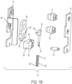
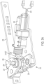
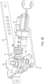
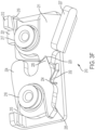
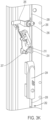
- FIG. 3A-3F depict a first exemplary embodiment of a latch 210.
- the latch 210 is shown interacting with an actuator 202 and striker assembly 204.
- the actuator 202 may form part of a larger assembly including the latch 210.
- the striker assembly 204 may form part of a larger assembly including the latch 210 and/or actuator 202.
- the actuator 202 is (optionally) an electric solenoid that is configured to be connected to a power source and a computer controller by wires 203. Upon receiving a command from the computer controller (not shown), the actuator 202 is configured to actuate (i.e., extend or retract or otherwise translate) a piston 205 from the end of actuator 202, and the piston 205 is configured to interact with a trigger 211 of the latch 210, as will be described later. Other types of actuators are known to those skilled in the art. Also, the actuator 202 may be omitted.
- the striker assembly 204 includes an elongated rail 208, and a striker 207 that is fixedly mounted to the rail 208 by a bracket 209 using fasteners.
- Rail 208 may be flat, as shown, or may be rounded, for example. The geometry and shape of rail 208 can vary.
- the rail 208 is movable with respect to the latch 210 in the direction of the arrows shown in FIG. 3C . Either the rail 208 moves with respect to latch 210, or the latch 210 moves with respect to the rail 208.
- the striker 207 is a cylindrical (or semi-cylindrical) member that is configured to interact with the pawl 224 of the latch 210.
- latch 210 generally comprises a rear frame member 212 and a front frame member 214 that are connected together by pins 217 and 218 and/or other fasteners.
- the rear frame member 212 includes a mounting surface and opening 213 to which the actuator 202 (not shown in FIGS. 3E and 3F ) is mounted by fasteners (not shown).
- a pawl 224 has an opening through which the pin 218 is positioned, and the pawl 224 moves (i.e., rotates) about the pin 218 between a closed position ( FIG. 3B ) and an open position ( FIG. 3C ).
- a torsion spring 215 is mounted around the pin 218 and includes a first free end that is mounted on the rear frame member 212 (or other stationary feature) and a second free end that is mounted to a bearing surface on the pawl 224. The spring 215 biases pawl 224 to the open position.
- a trigger 211 has an opening through which the pin 217 is positioned, and the trigger 211 moves (i.e., rotates) between a locked position ( FIG. 3F ) and an unlocked position ( FIG. 3C ).
- a torsion spring 219 is mounted around the pin 217 and includes a first free end that is mounted on the rear frame member 212 (or other stationary feature) and a second free end that is mounted to a bearing surface on the trigger 211. The spring 219 biases trigger 211 to the unlocked position.
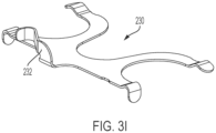
- a spring member 230 which is formed from a ductile and resilient material, is positioned at an elevation that is both above the frame member 212 and beneath the trigger 211 and pawl 224.
- the spring member 230 includes four legs depending therefrom that urge the trigger 211 and the pawl 224 toward the frame member 214, thereby preventing the trigger 211 and pawl 224 from rattling during operation.
- a spring arm 232 also extends from the spring member 230.
- the spring arm 232 is a flexible curved member that is positioned to interact with a perimeter surface of the pawl 224.
- the spring arm 232 in the closed position of the pawl 224, the spring arm 232 is seated in a concave recess, indent or depression 234 formed on the outer perimeter of the lower side of the pawl 224.
- the holding force exerted by the spring arm 232 onto the pawl 224 is greater than the force exerted by the torsion spring 215 such that the pawl 224 remains in the closed position even after the trigger 211 has been moved to the unlocked position ( FIG. 3B ).
- the spring arm 232 in the open position of the pawl 224, the spring arm 232 is seated in another concave recess, indent or depression 235 formed on the outer perimeter of the lower side of the pawl 224.
- a plurality of depressions 234/235 are defined on the lower perimeter side of the pawl 224.
- the latch 210 also may be considered a bi-stable latch because the latch 210 can remain in the open position until it is moved to the closed position and can also remain in the closed position until it is moved to the open position.
- a tab 221 extending from the perimeter of the trigger 211 bears on a bearing surface of the frame member 212.
- a v-shaped recess 223 formed along the perimeter of the trigger 211 is positioned within a correspondingly v-shaped projection 225 formed on the perimeter of the pawl 224. Engagement between the recess 223 and projection 225 as well as the tab 221 and frame 212 prevents the pawl 224 from moving in a counterclockwise direction (as viewed in FIG. 3F ) toward the open position.
- the trigger 211 includes a control surface 227, in the form of a bent projection, that protrudes from the latch 210 toward the actuator 202.
- the control surface 227 is positioned to interact with the piston 205 of the actuator 202.
- the piston 205 is configured to bear on the bearing surface 227 to move the trigger 211 from the locked position ( FIG. 3F ) to the unlocked position ( FIG. 3C ).
- control surface 227a has a hole or opening that may be connected to a cable (not shown), and the cable may be connected to an actuator (not shown) for pulling the cable to cause the trigger 211 to move from the locked position to the unlocked position.
- control surface 227b is provided in the form of a finger tab that is positioned on the top side of the trigger and is positioned to be accessed by (for example) a user for manually moving the trigger 211 to cause the trigger 211 to move from the locked position to the unlocked position.
- the latch 210 is shown in a locked and latched state.
- the locked and latched (i.e., closed) state the latch 210 retains the striker 207 within the pawl 224. If a user were attempt to move the striker 207 away from the latch 210 (e.g., by translating the rail 208), the latch 210 would prevent the movement of the striker 207 and rail 208 because the trigger 211 would prevent the pawl 224 from rotating in a counterclockwise direction (as viewed in FIG. 3F ) to the open position.
- the latch 210 is shown in an unlocked and latched state.
- the computer controller actuates the actuator 202, which causes the piston 205 of the actuator 202 to extend and bear on the control surface 227 of the trigger 211, which causes the trigger 211 to rotate in a counterclockwise direction (as viewed in FIG. 3F ) and against the bias of the spring 219.
- the pawl 224 remains in the closed state by virtue of the engagement between the spring arm 232 and the pawl 224.
- the latch 210 is shown in an unlocked and unlatched state.
- the user translates the rail 208 and striker 207 away from the latch 210.
- the striker 207 moves the pawl 224 (which is unlocked) in the counterclockwise direction (as viewed in FIG. 3F ) against the bias of the spring arm 232.
- the spring arm 232 slides along the lower surface of the pawl 224.
- the pawl 224 eventually releases the striker 207 as the striker 207 is moved away from the latch 210.
- the pawl 224 remains in the open state by virtue of the engagement between the spring arm 232 and the detent 235 of the pawl 224.
- the trigger 211 remains in the unlocked state due to the engagement between the piston 205 and the control surface 227 of the trigger 211.
- the latch 210 is shown in an unlocked and unlatched state.
- the computer controller actuates the actuator 202, which causes the piston 205 of the actuator 202 to retract and separate from the control surface 227 of the trigger 211.
- the torsion spring 219 returns the trigger 211 to its locked position whereupon the tab 221 bears on the frame member 212, as shown in FIG. 3F .
- the pawl 224 remains open.
- the user moves the striker 207 toward the latch 210.
- the striker 207 engages the opening in the pawl 224, and the pawl 224 rotates in a clockwise direction (as viewed in FIG. 3F ) against the bias of the spring 215.
- the projection 225 of the pawl 224 rides on the perimeter of the trigger 211 (and causes slight rotation of the trigger 211 against the bias of the spring 219) until the striker 207 bears on the frame members 212 and 214. And, at which time the projection 225 of the pawl 224 becomes seated in the recess 223 of the trigger 211.
- the latch 210 is then maintained in the locked and latched state of FIG. 3A .
- the latch 210, actuator 202 and rail 208 may be employed as part of a multi-point latching system 292 for securing a door 290 to a door frame or other structure.
- the multi-point latching system 292 comprises an actuator 294 in the form of a lever, handle or driver, for example.
- the actuator 294 is movable between a first position that corresponds to a locked state of the door 290, and a second position that corresponds to an unlocked state of the door 290, as is known in the art.
- the actuator 294 has an output end that is connected to the rail 208 of FIG. 3C . Moving the actuator 294 between the first and second positions causes the rail 208 to translate up and down, as is known in the art.
- One or more of the striker assemblies 204 are connected to the rail 208.
- One or more pawls 295 are individually connected to the door 290.
- the pawls 295 may be pivotably mounted to the door 290, for example.
- each pawl 295 is connected to a cam 296 that pivots on the door 290.
- Each pawl 295 is also connected to the rail 208, such that translation of the rail 208 causes the cams 296 and the pawls 295 that are connected thereto to pivot between locked and unlocked positions.
- the locked position the pawls 295 are oriented such that they retain the door 290 to the door frame or other structure.
- the pawls 295 are oriented such that they do not retain the door 290 to the door frame or other structure.
- Each guide 297 may include a rectangular through-hole for receiving the rail 208, in order to constrain the rail 208 in two translation degrees of freedom.
- One or more additional guides 298 are also mounted to the door 290. Each guide 298 may include an open ended slot for receiving the rail 208, in order to constrain the rail 208 in one translation degree of freedom.
- Each latch 210 is configured to interact with a striker 207 that is mounted to the rail 208, as was described previously.
- the latch 210 restrains the striker 207, as well as the entire multi-point latch system 292, from moving.
- the latch 210 does not prevent the striker 207, as well as the entire multi-point latch system 292, from moving.
- multi-point latching system 292 has been described for use with the latch 210, it should be understood that the multi-point latching system 292 may incorporate any of the latches described herein without extensive modification.
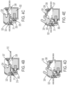
- FIG. 4A-4D depict a second exemplary embodiment of a latch 310.
- the latch 310 is similar to the latch 210 of FIG. 3A , and the primary differences therebetween will be described hereinafter.
- the latch 310 generally comprises a frame or housing comprising a rear frame member 312 and a front frame member 314 that are connected together by fasteners or clips, for example.
- Various components are positioned within the interior space defined by the frame, and those components will be described hereinafter.
- a pawl 324 includes co-aligned pins 318 that are positioned within openings 313 defined in the frame members.
- the pins 318 may be integral with the body of the pawl 324, or may comprise one or more separate components that are mounted to the pawl 324.
- the pawl 324 moves (i.e., rotates) about the openings 313 between a closed position ( FIG. 4B ) and an open position ( FIG. 4D ).
- the pawl 324 includes a concave area for receiving a striker, like the other pawls described above.
- a concave recess 325 ( FIG. 4C ) is formed along the perimeter of the pawl 324, and a corresponding projection 323 is formed on the perimeter of the trigger 311. Engagement between the recess 325 and projection 323 prevents the pawl 324 from rotating in a counterclockwise direction (as viewed in FIG. 4B ) toward the open position.
- An opening 328 ( FIG. 4A ) is provided in the pawl 324 to which a spring guide 330 is rotatably connected.
- the spring guide 330 is an elongated body having a first bifurcated connection end 331 that is rotatably positioned within the opening 328 in the pawl 324 by a pin 332 that is positioned through co-aligned holes in the bifurcated end 331.
- the second, opposite, end 334 of the spring guide 330 is substantially flat and is positioned to travel within an opening 336 defined in the frame. The end 334 moves in an unconstrained fashion within the opening 336 of the frame and without becoming detached from the frame as the pawl 324 moves between the open and closed positions.
- a compression spring 338 is positioned over the elongated portion of the spring guide 330.
- One end of the spring 338 is positioned to bear on a shoulder 337 ( FIG. 4D ) of the opening 336 of the frame, while the opposite end of the spring 338 is positioned to bear on the bifurcated connection end 331 of the spring guide 330.
- the spring 338 In the closed position of the pawl 324 shown in FIG. 4B , the spring 338 is configured to urge the pawl 324 in a counterclockwise position (as viewed in that figure) and to remain in the closed position. Conversely, in the open position of the pawl 324 shown in FIG. 4D , the spring 338 is configured to urge the pawl 324 in a clockwise position and to remain in the open position. Therefore, the latch 310 may also be considered a bi-stable latch because the latch 310 can remain in the open position until it is moved to the closed position and can also remain in the closed position until it is moved to the open position.
- the trigger 311 includes co-aligned pins 317 that are positioned within openings 315 ( FIG. 4A , one shown) defined in the frame members.
- the pins 317 may be integral with the body of the trigger 311, or may comprise one or more separate components that are mounted to the trigger 311.
- the trigger 311 moves (i.e., rotates) about the opening 315 ( FIG. 4A , one shown) between a locked position ( FIG. 4B ) and an unlocked position ( FIG. 4C ).
- the axes of rotation of the trigger 311 and the pawl 324 are parallel.
- the trigger 311 includes a control surface 327 in the form of a leg that extends from the body of the trigger 311.
- the control surface 327 is configured to be contacted by an actuator 302, as will be described later, for moving the trigger 311 between the locked and unlocked positions.
- An opening 321 is defined in the body of the trigger 311 for accommodating the coiled portion of a torsion spring 319.
- a pin (such as pin 317) may be positioned through the coiled portion of the spring 319 to retain the spring 319 in place.
- One leg of the torsion spring 319 is positioned against the trigger 311 while the other leg of the torsion spring 319 is positioned against a stationary surface, such as a surface on the frame.
- the spring 319 biases trigger 311 to the locked position.
- An actuator 302 is mounted to the frame and is configured to actuate (i.e., extend or retract or otherwise translate) a piston 305 from the end of actuator 302.
- the actuator 302 is a solenoid, however, other types of actuators are known to those skilled in the art. Like the above described actuators, the actuator 302 is connected to the computer controller for control purposes.
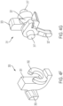
- a cap 350 is connected to the piston 305 in a fixed manner such that the cap 350 moves with the piston 305.
- the cap 350 has a J-shaped body 351, a C-clip 352 mounted to the curved end of the body 351, and a projection 353 that extends longitudinally and outwardly from the body 351.
- C-clip 352 and projection 353 may be integrated with the body 351, or those features may be separate components that are mounted to the body 351.
- the C-clip 352 is connected to the piston 305 in a non-rotatable manner.
- the projection 353 is configured to interact with the control surface 327 of the trigger 311 of the latch 310.
- a sensor 360 is mounted to the frame, and is configured to detect one or more of the rotational position, presence or absence of the pawl 324 (and/or trigger 311) and transmit a corresponding signal to the computer controller via a cable.
- the sensor 360 may be a switch, for example.
- Other means for sensing the closed or open state of the pawl 324 are known to those skilled in the art, such as magnetic sensors, proximity sensors, Hall-Effect sensor and optical sensors.
- the latch 310 is shown in a locked and latched state.
- the locked and latched (i.e., closed) state the latch 310 retains the striker within the pawl 324. If a user were attempt to move the striker away from the latch 310 (or vice versa), the latch 310 would prevent the movement of the striker because the trigger 311 would prevent the pawl 324 from rotating in a counterclockwise direction (as viewed in FIG. 4B ) to the open position.
- the latch 310 is shown in an unlocked and latched state.
- a user instructs the computer controller to actuate the actuator 302, which causes the piston 305 of the actuator 302 to retract.
- the computer controller may perform this unlocking step in response to an event, such as a vehicle being placed into the Park 'P' position.
- the projection 353 on the cap 350 bears on the control surface 327 of the trigger 311, which causes the trigger 311 to rotate in a counterclockwise direction (as viewed in FIG. 4C ) and against the bias of the spring 319. Rotation of the trigger 311 causes the projection 323 of the trigger 311 to separate from the recess 325 of the pawl 324. Once the recess 325 of the pawl 324 separates from the projection 323 of the trigger 311, the trigger 311 is maintained in the unlocked position, and the latch 310 is unlocked. In the unlocked state of the latch 310, the pawl 324 remains in the closed state by virtue of the bias of the spring 338 applied against the pawl 324.
- the senor 360 In the latched state, the sensor 360 detects the closed state of the pawl 324 and communicates the same to the computer controller.
- the computer controller may, for example, send a warning to the user if it is determined that the trigger 311 is unlocked (by virtue of the known position of the actuator 302) while another condition is present (e.g., a motor vehicle to which the latch is attached is being driven).
- the latch 310 is shown in an unlocked and unlatched state.
- the user translates the striker away from the latch 310 (or vice versa).
- the striker moves the pawl 324 (which is unlocked) in the counterclockwise direction (as viewed in FIG. 4D ) to the open position and against the bias of the spring 338.
- the pawl 324 remains in the open state by virtue of the bias of the spring 338 applied against the pawl 324.
- the latch 310 is shown in a locked and unlatched state.
- a user instructs the computer controller to actuate the actuator 302, which causes the piston 305 of the actuator 302 to extend.
- the trigger 311 is permitted to rotate in the clockwise direction and return to the locked position under the bias of the spring 319.
- the pawl 324 is maintained in the open/unlatched state, the trigger 311 remains rotated as shown in FIG. 4E due to the interference between the pawl 324 and the trigger 311.
- the force indirectly applied onto the pawl 324 by the spring 319 is less than the force indirectly applied onto the pawl 324 by the spring 338.
- the user moves the striker toward the latch 310.
- the striker engages the opening in the pawl 324, and the pawl 324 rotates in a clockwise direction (as viewed in FIG. 4B ) against the bias of the spring 338.
- the projection 323 of the trigger 311 rides on the perimeter of the pawl 324 due to the bias of the spring 319 until the striker is captivated by the pawl 324 in the latched position. And, at which time the projection 323 of the trigger 311 is seated in the recess 325 of the pawl 324, thereby locking the pawl 324.
- the latch 310 is then maintained in the locked and latched state of FIG. 4B .
- the latch 310 may be moved between the unlocked states shown in FIGs. 4C and 4D without locking the pawl 324 using the trigger 311. Also, the user can move the trigger 311 between the locked and unlocked states (by way of the computer controller or other device) as desired.
- FIG. 5A-5H depict a third exemplary embodiment of a latch 410.
- the latch 410 is similar to the latch 210, and the primary differences between those latches will be described hereinafter.
- the latch 410 is shown interacting with an actuator 402 and a release cable 409.
- the actuator 402 is substantially similar to the actuator 202.
- the actuator 402 Upon receiving a command from the computer controller (not shown), the actuator 402 is configured to actuate (i.e., extend or retract) a piston 405 from the end of actuator 402, and the piston 405 is configured to interact with a trigger 411 of the latch 410 for moving the trigger 411 from a locked position to an unlocked position.
- the release cable 409 is also connected to an opening in the trigger 411. In operation, the cable 409 may be pulled by either manual or automated means to release the trigger 411 (i.e., move the trigger 411 from the locked position to the unlocked position).
- the actuator 402 and cable 409 may form part of the latch 410, or may form part of a separate assembly.
- the actuator 402 and/or cable 409 are omitted in various figures.
- latch 410 generally comprises a rear frame member 412 and a front frame member 414 (omitted in FIGs. 5B and 5C ) that are connected together by pins 417 and 418 and/or other fasteners.
- a pawl 424 has an opening through which the pin 418 is positioned, and the pawl 424 moves (i.e., rotates) about the pin 418 between a closed position ( FIG. 5E ) and an open position ( FIG. 5F ).
- a torsion spring 415 is mounted around the pin 418 and includes a first free end 415a that bears on the rear frame member 412 and a second free end 415b that is mounted to in a depression 434 formed on the perimeter of the pawl 424.
- the spring 415 biases pawl 424 to the open position.
- a trigger 411 has an opening through which the pin 417 is positioned, and, like the trigger 211, the trigger 411 moves (i.e., rotates) between a locked position and an unlocked position.
- a torsion spring 419 is mounted around the pin 417 and includes a first free end 419a that bears on the rear frame member 412 and a second free end that is mounted to a bearing surface on the trigger 411. The spring 419 biases trigger 411 to the locked position.
- a spring member 430 which is formed from a ductile and resilient material, is sandwiched between (i) the frame member 414 and (ii) the trigger 411 and pawl 424.
- the spring member 430 includes four legs depending therefrom that urge the trigger 411 and the pawl 424 toward the frame member 412, thereby preventing the trigger 411 and pawl 424 from rattling during operation.
- First and second spring arms 432 and 433 extend from the spring member 430.
- the first spring arm 432 is a flexible curved member that is positioned to interact with a surface of the pawl 424.
- the second spring arm 433 is a flexible curved member that is positioned to interact with a surface of a striker bar 450.
- the first spring arm 432 is seated in a concave recess, indent or depression 434 formed on the outer perimeter of the lower side of the pawl 224.
- the spring arm 432 rests above the second free end 415b of the spring 415.
- the holding force exerted by the spring arm 432 onto the pawl 424 is greater than the force exerted by the torsion spring 415 such that the pawl 424 remains in the closed position even after the trigger 411 has been moved to the unlocked position.
- the latch 410 in the open position of the pawl 424, the spring arm 432 is seated in another concave recess, indent or depression 435 formed on the outer perimeter of the lower side of the pawl 424.
- the force exerted by the spring arm 432 onto the pawl 424 retains the pawl in the open position. Therefore, like the latch 10, the latch 410 also may be considered a bi-stable latch because the latch 410 can remain in the open position until it is moved to the closed position and can also remain in the closed position until it is moved to the open position.
- the spring arm 432 may be omitted if so desired, and, in such case, the latch 410 would not be bi-stable.
- the trigger 411 includes a tab 421 extending from the perimeter of the trigger 411.
- the tab 421 bears on a bearing surface of the frame member 412.
- a v-shaped recess 423 is formed along the perimeter of the trigger 411, and a corresponding v-shaped projection 425 formed on the perimeter of the pawl 424 is positioned within the recess 423. Engagement between the recess 423 and projection 425 as well as the tab 421 and frame 412 prevents the pawl 424 from moving in a counterclockwise direction (as viewed in FIG. 5F ) toward the open position.
- the trigger 411 includes a control surface 427, in the form of a vertically extending projection, that is configured to interact with the piston 405 of the actuator 402.
- the piston 405 is configured to bear on the bearing surface 427 to move the trigger 411 from the locked position ( FIG. 5H ) to the unlocked position.
- the control surface 427 also has a hole or opening 427a that is connected to the cable 409, as described earlier, for moving the trigger 411 from the locked position ( FIG. 5H ) to the unlocked position.
- a striker bar 450 is pivotably mounted to an opening 451 ( FIG. 5D ) in the center of the trigger 411 by a pin 452.
- the pin 452 passes through an opening 453 in the striker bar 450 and the opening 451 in the trigger 411.
- Striker bar 450 is directly mounted to the trigger 411.
- Striker bar 450 is configured to rotate with respect to the trigger 411 about the pin 452.
- the perimeter of the striker bar 450 includes a concave portion 459 that is configured to interact with the striker 407.
- the striker bar 450 is an elongated member having an outer surface and an inner surface.
- a projection or tab 455 projects from the inner surface of the striker bar 450.
- the tab 455 is configured to interact with a wiper arm 458 of a switch 460.
- the switch 460 is connected to a computer controller (not shown) by a cable 461 that is terminated at a connector.
- a cover 462 is positioned over the switch 460 and at least a portion of the cabling extending therefrom to partially conceal the switch 460.
- the switch 460 may be fixedly connected to the frame member 412. In operation, in an open state of the switch 460, the tab 455 of the striker bar 450 is not positioned in contact with the wiper arm 458 of the switch 460, thereby indicating that (i) the striker 407 is not positioned within the interior of the latch 410, and/or (ii) the trigger 411 is rotated to the unlocked position.
- the tab 455 is positioned in contact with the wiper arm 458 of the switch 460, thereby indicating that (i) the striker 407 is positioned within the interior of the latch 410, and (ii) the trigger 411 is rotated to the locked position.
- the switch 460 When the switch 460 is closed, it transmits a corresponding 'closed' signal to the computer controller via the cable 461.
- Other means for sensing the presence or absence of the striker bar 450 are known to those skilled in the art, such as magnetic sensors, proximity sensors, Hall-Effect sensor and optical sensors.
- the switch 460 may be more generally referred to as a means for sensing a position, presence or absence of striker bar 450.
- the second spring arm 433 of the spring member 430 is positioned to bear on the perimeter surface of the striker bar 450.
- the second spring arm 433 is configured to bias the striker bar 450 in the direction of the striker 407.
- moving the striker 407 into the latch 410 causes the striker bar 450 to rotate with respect to the trigger 411 against the bias of the spring arm 433.
- rotation of the striker bar 450 in the counterclockwise direction is limited by the spring arm 433, and rotation of the striker bar 450 in the clockwise direction is limited by the pin 417.
- first and second spring arms may be replaced by simple spring elements, and that the first and second spring arms are not required to be associated with the same spring component.
- first and second spring arms may be referred to more generally as spring elements herein.
- the rear frame member 412 includes a bent tab section 470 having an L-shape that extends inwardly toward the interior of the frame.
- the bent tab section 470 is positioned adjacent and extends from the concave opening 471 in the rear frame member 412 that is provided for accommodating the striker 407.
- the free end of the bent tab section 470 extends upwardly toward the striker 407.
- the bent tab section 470 is formed integrally with the frame member 412.
- the bent tab section 470 is arranged between the pins 417 and 418 as viewed in a longitudinal direction.
- the bent tab section 470 may be referred to herein more generally as a projection.
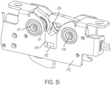
- a bumper 474 is mounted on the bent tab section 470.
- the bumper 474 may be composed of an elastomeric material such as rubber, for example.
- the top end of the bumper 474 includes a concave surface 476 that is configured to interact with the cylindrical body of the striker 407. In operation, the striker 407 contacts the concave surface 476 without producing an audible bump, squeak or rattle.
- the bottom end of the bumper 474 includes an opening 478 for receiving the free end of the bent tab section 470.
- the bumper 474 may be connected to the bent tab section 470 using adhesive, for example.
- Two elongated arms 480 are positioned on opposite sides of the opening 478.
- the arms 480 are positioned in the channels that run adjacent the bent tab section 470, as best shown in FIG. 5I .
- An exterior surface of the bumper 474 is maintained flush with an exterior surface of the frame member 412 and extends within an interior region of the frame formed by frame members 412 and 414.
- An opening 482, in the form of a rectangular aperture, extends across the width of the bumper 474 (i.e., in the longitudinal direction), and intersects the opening 478.
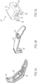
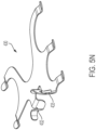
- the opening 482 receives barbs 473 ( FIG. 5M ) on the bent tab section 470 for holding the bumper 474 to the frame.
- the latch 410 is shown in a locked and latched state.
- the locked and latched (i.e., closed) state the latch 410 retains the striker 407 within the pawl 424.
- the pawl 424 is held in a fixed rotational position by the trigger 411 due to the interface between the surfaces 423 and 425 (see FIG. 5H ).
- the switch 460 is maintained in a closed position, thereby indicating that (i) the striker 407 is positioned within the interior of the latch 410, and (ii) the trigger 411 is rotated to the locked position.
- the latch 410 is shown in an unlocked and unlatched state.
- the computer controller actuates the actuator 402, which causes the piston 405 of the actuator 402 to extend and bear on the control surface 427 of the trigger 411, which causes the trigger 411 to rotate in a counterclockwise direction (as viewed in FIG. 5F ) and against the bias of the spring 419. Rotation of the trigger 411 may result in slight rotation of the pawl 424 until the recess 423 of the trigger separates from the projection 425 of the pawl 424.
- translating the release cable 409 would also result in counterclockwise rotation of the trigger 411.
- the striker 407 moves the pawl 424 (which is unlocked) in the counterclockwise direction (as viewed in FIG. 5F ) against the bias of the spring arm 432.
- the spring arm 432 slides along the surface of the pawl 424.
- the pawl 424 eventually releases the striker 407 as the striker 407 is moved away from the latch 410.
- the striker 407 separates from the striker bar 450, and, in the absence of the striker 407, the second spring arm 433 urges the striker bar 450 to rotate in the clockwise direction.
- the tab 455 of the striker bar 450 separates from the wiper arm 458 of the switch 460, thereby indicating that (i) the striker 407 is not positioned within the interior of the latch 410, and/or (ii) the trigger 411 is rotated to the unlocked position.
- the computer controller identifies this change in state due to the signals (or absence of signals) transmitted from switch 460.
- the pawl 424 remains in the open state by virtue of the engagement between the spring arm 432 and the pawl 424 as well as the force exerted by the spring 415.
- the trigger 411 remains in the unlocked state due to the engagement between the piston 405 and the control surface 427 of the trigger 411.
- the computer controller actuates the actuator 402, which causes the piston 405 of the actuator 402 to retract and separate from the control surface 427 of the trigger 411.
- the torsion spring 419 then returns the trigger 411 to its locked position.
- the pawl 424 remains open due to the bearing force of the spring arm 432.
- the user moves the striker 407 toward the latch 410.
- the striker 407 engages the concave opening in the pawl 424, and the pawl 424 rotates in a clockwise direction against the bias of the spring 415.
- the projection 425 of the pawl 424 rides on the perimeter of the trigger 411 (and causes slight rotation of the trigger 411 against the bias of the spring 419) until the striker 407 bears on the bumper 474. And, at which time the projection 425 of the pawl 424 is seated in the recess 423 of the trigger 411.
- the latch 410 is then maintained in the locked and latched state of FIG. 5E .
- the tab 455 of the striker bar 450 contacts the wiper arm 458 of the switch 460, thereby indicating that (i) the striker 407 is positioned within the interior of the latch 410, and (ii) the trigger 411 is rotated to the locked position.
Landscapes
- Engineering & Computer Science (AREA)
- Mechanical Engineering (AREA)
- Lock And Its Accessories (AREA)
Claims (13)
- Verriegelungsanordnung (210, 310, 410), umfassend:einen Rahmen (212, 214, 412, 414);eine Sperrklinke (224, 295, 324, 424), die eine Fläche zur Aufnahme eines Schlagbolzens (207, 407) aufweist und mit dem Rahmen (212, 214, 412, 414) zwischen einer offenen und einer geschlossenen Position beweglich gekoppelt ist, wobei die Sperrklinke (224, 295, 324, 424) in der geschlossenen Position so positioniert ist, dass sie den Schlagbolzen (207, 407) an dem Riegel hält, 424) so positioniert ist, dass sie den Anschlag (207, 407) an der Verriegelungsanordnung (210, 310, 410) festhält, und wobei die Sperrklinke (224, 295, 324, 424) in der offenen Position nicht so positioniert ist, dass sie den Anschlag (207, 407) an der Verriegelungsanordnung (210, 310, 410) festhält; undeine Feder (230, 430, 232, 432), die gegen eine Umfangsfläche der Sperrklinke (224, 295, 324, 424) positioniert ist, wobei in der geschlossenen Position der Sperrklinke (224, 295, 324, 424) die Feder (230, 430, 232, 432) so konfiguriert ist, dass sie die Sperrklinke (224, 295, 324, 424) so vorspannt, dass die Sperrklinke (224, 295, 324, 424) in die geschlossene Position zurückkehrt, Die Feder (230, 430, 232, 432) ist so konfiguriert, dass sie die Sperrklinke (224, 295, 324, 424) so vorspannt, dass die Sperrklinke (224, 295, 324, 424) in der geschlossenen Position verbleibt, dadurch gekennzeichnet, dass die Verriegelungsbaugruppe ferner eine Vielzahl von Vertiefungen (234, 235, 434, 435) umfasst, die auf der Umfangsfläche der Sperrklinke (224, 295, 324, 424) ausgebildet sind, wobei jede Vertiefung (234, 234, 434, 435) so konfiguriert ist, dass sie die Feder (230, 430, 232, 432) aufnimmt, wobei in der offenen Position der Sperrklinke (224, 295, 324, 424) die Feder (230, 430, 232, 432) in einer der beiden Positionen sitzt, 432) in einer der Vertiefungen (234, 235, 434, 435) sitzt und in der geschlossenen Stellung der Sperrklinke (224, 295, 324, 424) die Feder (230, 430, 232, 432) in einer anderen der Vertiefungen (234, 235, 434, 435) sitzt.
- Verriegelungsvorrichtung nach Anspruch 1, wobei die Feder (230, 430) ein gebogener Federarm (232, 432) ist.
- Verriegelungsanordnung nach Anspruch 1, die ferner einen Auslöser (211, 311, 411) umfasst, der an dem Rahmen (212, 214, 412, 414) angebracht und so konfiguriert ist, dass er die Sperrklinke (224, 295, 324, 424) in einem verriegelten Zustand hält, während die Sperrklinke (224, 424) in der geschlossenen Position gehalten wird.
- Verriegelungsanordnung nach Anspruch 3, wobei der Auslöser (211, 311, 411) eine Steuerfläche (227, 327, 427) aufweist, die so konfiguriert ist, dass sie bewegt werden kann, um den Auslöser (211, 311, 411) von der Sperrklinke (224, 295, 324, 424) zu lösen, so dass sich die Sperrklinke (224, 295, 324, 424) in die offene Position bewegen kann.
- Verriegelungsanordnung nach Anspruch 4 umfasst ferner einen Aktuator, der so konfiguriert ist, dass er die Steuerfläche (227, 327, 427) des Auslösers (211, 311, 411) bewegt.
- Fallenanordnung nach Anspruch 1 umfasst ferner eine Torsionsfeder (215, 219, 232, 415, 419) zum Vorspannen der Sperrklinke (224, 295, 324, 424) in Richtung der offenen Position.
- Verriegelungsanordnung nach Anspruch 3 umfasst ferner eine Lasche (221, 421), die sich von einem Umfang des Auslösers (211, 311, 411) erstreckt und so konfiguriert ist, dass sie auf einer Lagerfläche des Rahmens aufliegt.
- Verriegelungsanordnung nach Anspruch 7, die ferner eine v-förmige Aussparung umfasst, die entlang des Umfangs des Drückers (211, 311, 411) ausgebildet ist und innerhalb eines entsprechend v-förmigen Vorsprungs (225, 425) positioniert ist, der am Umfang der Sperrklinke (224, 295, 324, 424) ausgebildet ist, so dass ein Eingriff zwischen der Aussparung und dem Vorsprung (225, 425) und zwischen der Lasche (221, 421) und dem Rahmen (212, 214, 412, 414) verhindert, dass sich die Sperrklinke (224, 295, 324, 424) in Richtung der offenen Position bewegt.
- Verriegelungsanordnung nach Anspruch 8, wobei der Vorsprung (225, 425) der Sperrklinke (224, 295, 324, 424) so konfiguriert ist, dass er entlang des Umfangs des Abzugs (211, 311, 411) läuft, bis der Vorsprung der Sperrklinke (224, 295, 324, 424) in der Aussparung des Abzugs (211, 311, 411) sitzt.
- Verriegelungsanordnung nach Anspruch 9, wobei der Vorsprung (225, 425) der Sperrklinke (224, 295, 324, 424) den Abzug (211, 311, 411) dazu bringt, sich gegen die Vorspannung der Feder (230, 430, 232, 432) zu drehen.
- Mehrpunkt-Verriegelungssystem für eine Tür, umfassend:ein Betätigungselement in Form eines Riegels (210, 310, 410), Hebels oder Griffs, wobei das Betätigungselement so konfiguriert ist, dass es zwischen einer ersten Position und einer zweiten Position bewegt werden kann;eine längliche Schiene oder Stange, die mit dem Betätigungselement verbunden und so konfiguriert ist, dass sie sich in Reaktion auf die Bewegung des Betätigungselements zwischen der ersten und der zweiten Position bewegt;eine Vielzahl von Sperrklinken (224, 295, 324, 424), die so konfiguriert sind, dass sie an der Tür montiert werden können, wobei die Sperrklinken (224, 295, 324, 424) jeweils mit der Schiene verbunden sind, so dass eine Bewegung der Schiene bewirkt, dass sich die Sperrklinken (224, 295, 324, 424) zwischen einer verriegelten und einer entriegelten Position bewegen;einen Anschlag (207, 407), der an der Schiene angebracht ist; undeinen Riegel (210, 310, 410), der so konfiguriert ist, dass er an der Tür angebracht werden kann, wobei der Riegel (210, 310, 410) Folgendes umfasst: (i) einen Rahmen (212, 214, 412, 414), (ii) eine Klinke (224, 424) mit einer Fläche zur Aufnahme des Schlagbolzens (207, 407), die beweglich mit dem Rahmen (212, 214, 412, 414) zwischen einer offenen und einer geschlossenen Position gekoppelt ist, wobei die Klinke (224, 424) in der geschlossenen Position so positioniert ist, dass sie den Schlagbolzen (207, 407) zurückhält, 424) so positioniert ist, dass sie den Schlagbolzen (207, 407) an dem Riegel (210, 310, 410) festhält, und wobei die Sperrklinke (224, 295, 324, 424) in der offenen Position nicht so positioniert ist, dass sie den Schlagbolzen (207, 407) an dem Riegel (210, 310, 410) zu halten, und (iii) eine Feder (215, 219, 232, 415, 419), die mit der Sperrklinke (224, 295, 324, 424) verbunden ist, wobei in der geschlossenen Position der Sperrklinke (224, 295, 324, 424) die Feder (215, 219, 232, 415, 419) so konfiguriert ist, dass sie die Sperrklinke (224, 295, 324, 424) so vorspannt, dass die Sperrklinke (224, 295, 324, 424) in der geschlossenen Position verbleibt, dadurch gekennzeichnet, dass die Verriegelungsbaugruppe ferner eine Vielzahl von Vertiefungen (234, 235, 434, 435) umfasst, die an der Umfangsfläche der Sperrklinke (224, 295, 324, 424) ausgebildet sind, wobei jede Vertiefung (234, 235, 434, 435) so konfiguriert ist, dass sie die Sperrklinke (224, 295, 324, 424) aufnimmt, 435) so konfiguriert ist, dass sie die Feder (230, 430, 232, 432) aufnimmt, wobei in der offenen Position der Sperrklinke (224, 295, 324, 424) die Feder (230, 430, 232, 432) in einer der Vertiefungen (234, 235, 434, 435) sitzt, und in der geschlossenen Stellung der Sperrklinke (224, 295, 324, 424) die Feder (230, 430, 282, 432) in einer anderen der Vertiefungen (234, 235, 434, 435) sitzt.
- Mehrpunkt-Verriegelungssystem nach Anspruch 11, wobei das Schloss (210, 310, 410) ferner eine Torsionsfeder (215, 219, 232, 415, 419) zum Vorspannen der Sperrklinke (224, 295, 324, 424) in Richtung der offenen Position umfasst.
- Türanordnung mit dem Mehrpunkt-Verriegelungssystem nach Anspruch 11.
Priority Applications (1)
| Application Number | Priority Date | Filing Date | Title |
|---|---|---|---|
| EP25175437.0A EP4575155A3 (de) | 2020-05-22 | 2021-05-21 | Drehriegel mit federführung |
Applications Claiming Priority (2)
| Application Number | Priority Date | Filing Date | Title |
|---|---|---|---|
| US202063028915P | 2020-05-22 | 2020-05-22 | |
| PCT/US2021/033529 WO2021237007A1 (en) | 2020-05-22 | 2021-05-21 | Rotary latch with spring guide |
Related Child Applications (1)
| Application Number | Title | Priority Date | Filing Date |
|---|---|---|---|
| EP25175437.0A Division EP4575155A3 (de) | 2020-05-22 | 2021-05-21 | Drehriegel mit federführung |
Publications (2)
| Publication Number | Publication Date |
|---|---|
| EP4153828A1 EP4153828A1 (de) | 2023-03-29 |
| EP4153828B1 true EP4153828B1 (de) | 2025-05-14 |
Family
ID=76444659
Family Applications (2)
| Application Number | Title | Priority Date | Filing Date |
|---|---|---|---|
| EP25175437.0A Pending EP4575155A3 (de) | 2020-05-22 | 2021-05-21 | Drehriegel mit federführung |
| EP21732744.4A Active EP4153828B1 (de) | 2020-05-22 | 2021-05-21 | Drehriegel mit federführung |
Family Applications Before (1)
| Application Number | Title | Priority Date | Filing Date |
|---|---|---|---|
| EP25175437.0A Pending EP4575155A3 (de) | 2020-05-22 | 2021-05-21 | Drehriegel mit federführung |
Country Status (6)
| Country | Link |
|---|---|
| US (1) | US20230175295A1 (de) |
| EP (2) | EP4575155A3 (de) |
| KR (2) | KR20250001557U (de) |
| CN (2) | CN115667649B (de) |
| BR (1) | BR112022023165A2 (de) |
| WO (1) | WO2021237007A1 (de) |
Family Cites Families (10)
| Publication number | Priority date | Publication date | Assignee | Title |
|---|---|---|---|---|
| GB315027A (en) * | 1928-04-18 | 1929-07-11 | George Washington Pirrie Johns | A new or improved combination latch and lock fastening for doors and the like |
| FR1013656A (fr) * | 1950-02-21 | 1952-08-01 | Perfectionnements apportés aux systèmes de fermeture pour portes ou autres éléments, notamment pour portes étanches | |
| US3659886A (en) * | 1970-05-01 | 1972-05-02 | Sealth Aero Marine Co | Aircraft panels with precisely adjustable and easy action spring toggle latch |
| US3713681A (en) * | 1971-08-27 | 1973-01-30 | Coleman Co | Safety latch assembly for picnic coolers |
| US4687237A (en) * | 1986-05-01 | 1987-08-18 | Southco, Inc. | Over-center toggle latch |
| GB8802004D0 (en) * | 1988-01-29 | 1988-02-24 | Gen Electric Co Plc | Sealed cabinet |
| GB2297578A (en) * | 1995-02-02 | 1996-08-07 | Ind Ragi D A | Drawer closure safety device |
| US6109667A (en) * | 1995-10-10 | 2000-08-29 | Collins; Matthew J. | Over-center toggle latch with integral switch |
| GB0703597D0 (en) * | 2007-02-23 | 2007-04-04 | Meritor Technology Inc | Latch assembley |
| KR101972508B1 (ko) * | 2016-08-19 | 2019-04-26 | 주식회사 우보테크 | 차량용 도어 래치 시스템 |
-
2021
- 2021-05-21 KR KR2020257000065U patent/KR20250001557U/ko active Pending
- 2021-05-21 US US17/925,632 patent/US20230175295A1/en active Pending
- 2021-05-21 KR KR2020227000065U patent/KR200499649Y1/ko active Active
- 2021-05-21 EP EP25175437.0A patent/EP4575155A3/de active Pending
- 2021-05-21 CN CN202180037466.7A patent/CN115667649B/zh active Active
- 2021-05-21 BR BR112022023165A patent/BR112022023165A2/pt unknown
- 2021-05-21 WO PCT/US2021/033529 patent/WO2021237007A1/en not_active Ceased
- 2021-05-21 EP EP21732744.4A patent/EP4153828B1/de active Active
- 2021-05-21 CN CN202510750225.7A patent/CN120331556A/zh active Pending
Also Published As
| Publication number | Publication date |
|---|---|
| CN115667649B (zh) | 2025-07-18 |
| EP4575155A2 (de) | 2025-06-25 |
| US20230175295A1 (en) | 2023-06-08 |
| CN115667649A (zh) | 2023-01-31 |
| KR20250001557U (ko) | 2025-10-21 |
| EP4153828A1 (de) | 2023-03-29 |
| CN120331556A (zh) | 2025-07-18 |
| KR20230000232U (ko) | 2023-01-30 |
| EP4575155A3 (de) | 2025-10-01 |
| KR200499649Y1 (ko) | 2025-10-13 |
| BR112022023165A2 (pt) | 2022-12-20 |
| WO2021237007A1 (en) | 2021-11-25 |
Similar Documents
| Publication | Publication Date | Title |
|---|---|---|
| US7832239B2 (en) | Lock apparatus for a glove box of a vehicle | |
| JP6155488B2 (ja) | 複数パーツを備えた爪部を有するロック装置 | |
| US7188871B2 (en) | Door lock mechanism and door lock unit | |
| EP1330584B1 (de) | Verriegelungseinrichtung | |
| US5423582A (en) | Power-assist motor-vehicle door latch | |
| US8191935B2 (en) | Glove box assembly for a dashboard of a motor vehicle | |
| EP2053186B1 (de) | Vorrichtung zum Verhindern der Entriegelung einer Türklinke | |
| US20150008680A1 (en) | Interior apparatus of a vehicle | |
| US20020117865A1 (en) | Inner door handle for automobiles | |
| KR20120096938A (ko) | 차량용 도어 래치 장치에서의 액추에이터 | |
| US6592157B1 (en) | Latch | |
| US20250146330A1 (en) | Method and device for sensing a striker within a rotary latch | |
| CN110114542B (zh) | 箱子闩锁 | |
| CN107257877B (zh) | 机动车门锁 | |
| EP4575155A2 (de) | Drehriegel mit federführung | |
| US8091933B1 (en) | Heavy duty door latch and release modules | |
| EP1179108B1 (de) | Verschluss | |
| JPH08312225A (ja) | 耐震ラッチ錠 | |
| US20250243695A1 (en) | Safety device for a vehicle door handle assembly | |
| JP2007045264A (ja) | エンジンフードロック装置 | |
| US20240209656A1 (en) | Latch system with actuator, position sensor, or actuator and position sensor | |
| WO2011002770A1 (en) | Vehicle door-latch manual release |
Legal Events
| Date | Code | Title | Description |
|---|---|---|---|
| STAA | Information on the status of an ep patent application or granted ep patent |
Free format text: STATUS: UNKNOWN |
|
| STAA | Information on the status of an ep patent application or granted ep patent |
Free format text: STATUS: THE INTERNATIONAL PUBLICATION HAS BEEN MADE |
|
| PUAI | Public reference made under article 153(3) epc to a published international application that has entered the european phase |
Free format text: ORIGINAL CODE: 0009012 |
|
| STAA | Information on the status of an ep patent application or granted ep patent |
Free format text: STATUS: REQUEST FOR EXAMINATION WAS MADE |
|
| 17P | Request for examination filed |
Effective date: 20221216 |
|
| AK | Designated contracting states |
Kind code of ref document: A1 Designated state(s): AL AT BE BG CH CY CZ DE DK EE ES FI FR GB GR HR HU IE IS IT LI LT LU LV MC MK MT NL NO PL PT RO RS SE SI SK SM TR |
|
| DAV | Request for validation of the european patent (deleted) | ||
| DAX | Request for extension of the european patent (deleted) | ||
| STAA | Information on the status of an ep patent application or granted ep patent |
Free format text: STATUS: EXAMINATION IS IN PROGRESS |
|
| 17Q | First examination report despatched |
Effective date: 20240627 |
|
| GRAP | Despatch of communication of intention to grant a patent |
Free format text: ORIGINAL CODE: EPIDOSNIGR1 |
|
| STAA | Information on the status of an ep patent application or granted ep patent |
Free format text: STATUS: GRANT OF PATENT IS INTENDED |
|
| RIC1 | Information provided on ipc code assigned before grant |
Ipc: E05B 15/04 20060101ALN20241031BHEP Ipc: E05B 15/02 20060101ALN20241031BHEP Ipc: E05C 19/02 20060101ALI20241031BHEP Ipc: E05C 9/02 20060101ALI20241031BHEP Ipc: E05B 15/00 20060101AFI20241031BHEP |
|
| INTG | Intention to grant announced |
Effective date: 20241203 |
|
| GRAS | Grant fee paid |
Free format text: ORIGINAL CODE: EPIDOSNIGR3 |
|
| GRAA | (expected) grant |
Free format text: ORIGINAL CODE: 0009210 |
|
| STAA | Information on the status of an ep patent application or granted ep patent |
Free format text: STATUS: THE PATENT HAS BEEN GRANTED |
|
| AK | Designated contracting states |
Kind code of ref document: B1 Designated state(s): AL AT BE BG CH CY CZ DE DK EE ES FI FR GB GR HR HU IE IS IT LI LT LU LV MC MK MT NL NO PL PT RO RS SE SI SK SM TR |
|
| REG | Reference to a national code |
Ref country code: GB Ref legal event code: FG4D |
|
| REG | Reference to a national code |
Ref country code: CH Ref legal event code: EP |
|
| REG | Reference to a national code |
Ref country code: IE Ref legal event code: FG4D |
|
| REG | Reference to a national code |
Ref country code: DE Ref legal event code: R096 Ref document number: 602021030780 Country of ref document: DE |
|
| PGFP | Annual fee paid to national office [announced via postgrant information from national office to epo] |
Ref country code: AT Payment date: 20250721 Year of fee payment: 5 |
|
| REG | Reference to a national code |
Ref country code: NL Ref legal event code: MP Effective date: 20250514 |
|
| PG25 | Lapsed in a contracting state [announced via postgrant information from national office to epo] |
Ref country code: PT Free format text: LAPSE BECAUSE OF FAILURE TO SUBMIT A TRANSLATION OF THE DESCRIPTION OR TO PAY THE FEE WITHIN THE PRESCRIBED TIME-LIMIT Effective date: 20250915 Ref country code: ES Free format text: LAPSE BECAUSE OF FAILURE TO SUBMIT A TRANSLATION OF THE DESCRIPTION OR TO PAY THE FEE WITHIN THE PRESCRIBED TIME-LIMIT Effective date: 20250514 Ref country code: FI Free format text: LAPSE BECAUSE OF FAILURE TO SUBMIT A TRANSLATION OF THE DESCRIPTION OR TO PAY THE FEE WITHIN THE PRESCRIBED TIME-LIMIT Effective date: 20250514 |
|
| PGFP | Annual fee paid to national office [announced via postgrant information from national office to epo] |
Ref country code: DE Payment date: 20250910 Year of fee payment: 5 |
|
| REG | Reference to a national code |
Ref country code: LT Ref legal event code: MG9D |
|
| PG25 | Lapsed in a contracting state [announced via postgrant information from national office to epo] |
Ref country code: NO Free format text: LAPSE BECAUSE OF FAILURE TO SUBMIT A TRANSLATION OF THE DESCRIPTION OR TO PAY THE FEE WITHIN THE PRESCRIBED TIME-LIMIT Effective date: 20250814 Ref country code: GR Free format text: LAPSE BECAUSE OF FAILURE TO SUBMIT A TRANSLATION OF THE DESCRIPTION OR TO PAY THE FEE WITHIN THE PRESCRIBED TIME-LIMIT Effective date: 20250815 |
|
| PG25 | Lapsed in a contracting state [announced via postgrant information from national office to epo] |
Ref country code: PL Free format text: LAPSE BECAUSE OF FAILURE TO SUBMIT A TRANSLATION OF THE DESCRIPTION OR TO PAY THE FEE WITHIN THE PRESCRIBED TIME-LIMIT Effective date: 20250514 Ref country code: NL Free format text: LAPSE BECAUSE OF FAILURE TO SUBMIT A TRANSLATION OF THE DESCRIPTION OR TO PAY THE FEE WITHIN THE PRESCRIBED TIME-LIMIT Effective date: 20250514 |
|
| REG | Reference to a national code |
Ref country code: AT Ref legal event code: MK05 Ref document number: 1794889 Country of ref document: AT Kind code of ref document: T Effective date: 20250514 |
|
| PG25 | Lapsed in a contracting state [announced via postgrant information from national office to epo] |
Ref country code: BG Free format text: LAPSE BECAUSE OF FAILURE TO SUBMIT A TRANSLATION OF THE DESCRIPTION OR TO PAY THE FEE WITHIN THE PRESCRIBED TIME-LIMIT Effective date: 20250514 |
|
| PG25 | Lapsed in a contracting state [announced via postgrant information from national office to epo] |
Ref country code: HR Free format text: LAPSE BECAUSE OF FAILURE TO SUBMIT A TRANSLATION OF THE DESCRIPTION OR TO PAY THE FEE WITHIN THE PRESCRIBED TIME-LIMIT Effective date: 20250514 |
|
| PG25 | Lapsed in a contracting state [announced via postgrant information from national office to epo] |
Ref country code: AT Free format text: LAPSE BECAUSE OF FAILURE TO SUBMIT A TRANSLATION OF THE DESCRIPTION OR TO PAY THE FEE WITHIN THE PRESCRIBED TIME-LIMIT Effective date: 20250514 |
|
| PG25 | Lapsed in a contracting state [announced via postgrant information from national office to epo] |
Ref country code: RS Free format text: LAPSE BECAUSE OF FAILURE TO SUBMIT A TRANSLATION OF THE DESCRIPTION OR TO PAY THE FEE WITHIN THE PRESCRIBED TIME-LIMIT Effective date: 20250814 |
|
| PG25 | Lapsed in a contracting state [announced via postgrant information from national office to epo] |
Ref country code: IS Free format text: LAPSE BECAUSE OF FAILURE TO SUBMIT A TRANSLATION OF THE DESCRIPTION OR TO PAY THE FEE WITHIN THE PRESCRIBED TIME-LIMIT Effective date: 20250914 |
|
| PG25 | Lapsed in a contracting state [announced via postgrant information from national office to epo] |
Ref country code: LV Free format text: LAPSE BECAUSE OF FAILURE TO SUBMIT A TRANSLATION OF THE DESCRIPTION OR TO PAY THE FEE WITHIN THE PRESCRIBED TIME-LIMIT Effective date: 20250514 |
|
| REG | Reference to a national code |
Ref country code: CH Ref legal event code: H13 Free format text: ST27 STATUS EVENT CODE: U-0-0-H10-H13 (AS PROVIDED BY THE NATIONAL OFFICE) Effective date: 20251223 |
|
| PG25 | Lapsed in a contracting state [announced via postgrant information from national office to epo] |
Ref country code: SM Free format text: LAPSE BECAUSE OF FAILURE TO SUBMIT A TRANSLATION OF THE DESCRIPTION OR TO PAY THE FEE WITHIN THE PRESCRIBED TIME-LIMIT Effective date: 20250514 Ref country code: DK Free format text: LAPSE BECAUSE OF FAILURE TO SUBMIT A TRANSLATION OF THE DESCRIPTION OR TO PAY THE FEE WITHIN THE PRESCRIBED TIME-LIMIT Effective date: 20250514 |
|
| PG25 | Lapsed in a contracting state [announced via postgrant information from national office to epo] |
Ref country code: LU Free format text: LAPSE BECAUSE OF NON-PAYMENT OF DUE FEES Effective date: 20250521 |
|
| PG25 | Lapsed in a contracting state [announced via postgrant information from national office to epo] |
Ref country code: CH Free format text: LAPSE BECAUSE OF NON-PAYMENT OF DUE FEES Effective date: 20250531 |
|
| PG25 | Lapsed in a contracting state [announced via postgrant information from national office to epo] |
Ref country code: CZ Free format text: LAPSE BECAUSE OF FAILURE TO SUBMIT A TRANSLATION OF THE DESCRIPTION OR TO PAY THE FEE WITHIN THE PRESCRIBED TIME-LIMIT Effective date: 20250514 |
|
| PG25 | Lapsed in a contracting state [announced via postgrant information from national office to epo] |
Ref country code: EE Free format text: LAPSE BECAUSE OF FAILURE TO SUBMIT A TRANSLATION OF THE DESCRIPTION OR TO PAY THE FEE WITHIN THE PRESCRIBED TIME-LIMIT Effective date: 20250514 |
|
| PG25 | Lapsed in a contracting state [announced via postgrant information from national office to epo] |
Ref country code: SK Free format text: LAPSE BECAUSE OF FAILURE TO SUBMIT A TRANSLATION OF THE DESCRIPTION OR TO PAY THE FEE WITHIN THE PRESCRIBED TIME-LIMIT Effective date: 20250514 |
|
| PG25 | Lapsed in a contracting state [announced via postgrant information from national office to epo] |
Ref country code: IT Free format text: LAPSE BECAUSE OF FAILURE TO SUBMIT A TRANSLATION OF THE DESCRIPTION OR TO PAY THE FEE WITHIN THE PRESCRIBED TIME-LIMIT Effective date: 20250514 |
|
| REG | Reference to a national code |
Ref country code: BE Ref legal event code: MM Effective date: 20250531 |
|
| PG25 | Lapsed in a contracting state [announced via postgrant information from national office to epo] |
Ref country code: RO Free format text: LAPSE BECAUSE OF FAILURE TO SUBMIT A TRANSLATION OF THE DESCRIPTION OR TO PAY THE FEE WITHIN THE PRESCRIBED TIME-LIMIT Effective date: 20250514 |
|
| REG | Reference to a national code |
Ref country code: DE Ref legal event code: R097 Ref document number: 602021030780 Country of ref document: DE |
|
| PG25 | Lapsed in a contracting state [announced via postgrant information from national office to epo] |
Ref country code: MC Free format text: LAPSE BECAUSE OF FAILURE TO SUBMIT A TRANSLATION OF THE DESCRIPTION OR TO PAY THE FEE WITHIN THE PRESCRIBED TIME-LIMIT Effective date: 20250514 |
|
| PLBE | No opposition filed within time limit |
Free format text: ORIGINAL CODE: 0009261 |
|
| STAA | Information on the status of an ep patent application or granted ep patent |
Free format text: STATUS: NO OPPOSITION FILED WITHIN TIME LIMIT |
|
| REG | Reference to a national code |
Ref country code: CH Ref legal event code: L10 Free format text: ST27 STATUS EVENT CODE: U-0-0-L10-L00 (AS PROVIDED BY THE NATIONAL OFFICE) Effective date: 20260325 |
|
| PGFP | Annual fee paid to national office [announced via postgrant information from national office to epo] |
Ref country code: GB Payment date: 20260313 Year of fee payment: 6 |
|
| PG25 | Lapsed in a contracting state [announced via postgrant information from national office to epo] |
Ref country code: IE Free format text: LAPSE BECAUSE OF NON-PAYMENT OF DUE FEES Effective date: 20250521 |
|
| PG25 | Lapsed in a contracting state [announced via postgrant information from national office to epo] |
Ref country code: BE Free format text: LAPSE BECAUSE OF NON-PAYMENT OF DUE FEES Effective date: 20250531 |
|
| PG25 | Lapsed in a contracting state [announced via postgrant information from national office to epo] |
Ref country code: FR Free format text: LAPSE BECAUSE OF NON-PAYMENT OF DUE FEES Effective date: 20250714 |
|
| 26N | No opposition filed |
Effective date: 20260217 |