EP4153367B1 - Vorrichtung und verfahren zur zerkleinerung von anorganischen abfällen - Google Patents
Vorrichtung und verfahren zur zerkleinerung von anorganischen abfällen Download PDFInfo
- Publication number
- EP4153367B1 EP4153367B1 EP21723923.5A EP21723923A EP4153367B1 EP 4153367 B1 EP4153367 B1 EP 4153367B1 EP 21723923 A EP21723923 A EP 21723923A EP 4153367 B1 EP4153367 B1 EP 4153367B1
- Authority
- EP
- European Patent Office
- Prior art keywords
- shredding
- materials
- machine
- knives
- chamber
- Prior art date
- Legal status (The legal status is an assumption and is not a legal conclusion. Google has not performed a legal analysis and makes no representation as to the accuracy of the status listed.)
- Active
Links
Images


Classifications
-
- B—PERFORMING OPERATIONS; TRANSPORTING
- B09—DISPOSAL OF SOLID WASTE; RECLAMATION OF CONTAMINATED SOIL
- B09B—DISPOSAL OF SOLID WASTE NOT OTHERWISE PROVIDED FOR
- B09B3/00—Destroying solid waste or transforming solid waste into something useful or harmless
- B09B3/30—Destroying solid waste or transforming solid waste into something useful or harmless involving mechanical treatment
- B09B3/35—Shredding, crushing or cutting
-
- B—PERFORMING OPERATIONS; TRANSPORTING
- B02—CRUSHING, PULVERISING, OR DISINTEGRATING; PREPARATORY TREATMENT OF GRAIN FOR MILLING
- B02C—CRUSHING, PULVERISING, OR DISINTEGRATING IN GENERAL; MILLING GRAIN
- B02C18/00—Disintegrating by knives or other cutting or tearing members which chop material into fragments
- B02C18/06—Disintegrating by knives or other cutting or tearing members which chop material into fragments with rotating knives
- B02C18/14—Disintegrating by knives or other cutting or tearing members which chop material into fragments with rotating knives within horizontal containers
- B02C18/142—Disintegrating by knives or other cutting or tearing members which chop material into fragments with rotating knives within horizontal containers with two or more inter-engaging rotatable cutter assemblies
-
- B—PERFORMING OPERATIONS; TRANSPORTING
- B02—CRUSHING, PULVERISING, OR DISINTEGRATING; PREPARATORY TREATMENT OF GRAIN FOR MILLING
- B02C—CRUSHING, PULVERISING, OR DISINTEGRATING IN GENERAL; MILLING GRAIN
- B02C18/00—Disintegrating by knives or other cutting or tearing members which chop material into fragments
- B02C18/06—Disintegrating by knives or other cutting or tearing members which chop material into fragments with rotating knives
- B02C18/16—Details
-
- B—PERFORMING OPERATIONS; TRANSPORTING
- B02—CRUSHING, PULVERISING, OR DISINTEGRATING; PREPARATORY TREATMENT OF GRAIN FOR MILLING
- B02C—CRUSHING, PULVERISING, OR DISINTEGRATING IN GENERAL; MILLING GRAIN
- B02C18/00—Disintegrating by knives or other cutting or tearing members which chop material into fragments
- B02C18/06—Disintegrating by knives or other cutting or tearing members which chop material into fragments with rotating knives
- B02C18/16—Details
- B02C18/22—Feed or discharge means
-
- B—PERFORMING OPERATIONS; TRANSPORTING
- B02—CRUSHING, PULVERISING, OR DISINTEGRATING; PREPARATORY TREATMENT OF GRAIN FOR MILLING
- B02C—CRUSHING, PULVERISING, OR DISINTEGRATING IN GENERAL; MILLING GRAIN
- B02C18/00—Disintegrating by knives or other cutting or tearing members which chop material into fragments
- B02C18/06—Disintegrating by knives or other cutting or tearing members which chop material into fragments with rotating knives
- B02C18/16—Details
- B02C18/22—Feed or discharge means
- B02C18/2216—Discharge means
-
- B—PERFORMING OPERATIONS; TRANSPORTING
- B02—CRUSHING, PULVERISING, OR DISINTEGRATING; PREPARATORY TREATMENT OF GRAIN FOR MILLING
- B02C—CRUSHING, PULVERISING, OR DISINTEGRATING IN GENERAL; MILLING GRAIN
- B02C18/00—Disintegrating by knives or other cutting or tearing members which chop material into fragments
- B02C18/06—Disintegrating by knives or other cutting or tearing members which chop material into fragments with rotating knives
- B02C18/16—Details
- B02C18/22—Feed or discharge means
- B02C18/2225—Feed means
- B02C18/2266—Feed means of revolving drum type
-
- B—PERFORMING OPERATIONS; TRANSPORTING
- B02—CRUSHING, PULVERISING, OR DISINTEGRATING; PREPARATORY TREATMENT OF GRAIN FOR MILLING
- B02C—CRUSHING, PULVERISING, OR DISINTEGRATING IN GENERAL; MILLING GRAIN
- B02C18/00—Disintegrating by knives or other cutting or tearing members which chop material into fragments
- B02C18/06—Disintegrating by knives or other cutting or tearing members which chop material into fragments with rotating knives
- B02C18/16—Details
- B02C18/22—Feed or discharge means
- B02C18/2225—Feed means
- B02C18/2275—Feed means using a rotating arm
-
- B—PERFORMING OPERATIONS; TRANSPORTING
- B02—CRUSHING, PULVERISING, OR DISINTEGRATING; PREPARATORY TREATMENT OF GRAIN FOR MILLING
- B02C—CRUSHING, PULVERISING, OR DISINTEGRATING IN GENERAL; MILLING GRAIN
- B02C18/00—Disintegrating by knives or other cutting or tearing members which chop material into fragments
- B02C18/06—Disintegrating by knives or other cutting or tearing members which chop material into fragments with rotating knives
- B02C18/16—Details
- B02C18/22—Feed or discharge means
- B02C18/2225—Feed means
- B02C18/2291—Feed chute arrangements
-
- B—PERFORMING OPERATIONS; TRANSPORTING
- B02—CRUSHING, PULVERISING, OR DISINTEGRATING; PREPARATORY TREATMENT OF GRAIN FOR MILLING
- B02C—CRUSHING, PULVERISING, OR DISINTEGRATING IN GENERAL; MILLING GRAIN
- B02C18/00—Disintegrating by knives or other cutting or tearing members which chop material into fragments
- B02C18/06—Disintegrating by knives or other cutting or tearing members which chop material into fragments with rotating knives
- B02C18/16—Details
- B02C18/24—Drives
-
- B—PERFORMING OPERATIONS; TRANSPORTING
- B02—CRUSHING, PULVERISING, OR DISINTEGRATING; PREPARATORY TREATMENT OF GRAIN FOR MILLING
- B02C—CRUSHING, PULVERISING, OR DISINTEGRATING IN GENERAL; MILLING GRAIN
- B02C25/00—Control arrangements specially adapted for crushing or disintegrating
-
- B—PERFORMING OPERATIONS; TRANSPORTING
- B02—CRUSHING, PULVERISING, OR DISINTEGRATING; PREPARATORY TREATMENT OF GRAIN FOR MILLING
- B02C—CRUSHING, PULVERISING, OR DISINTEGRATING IN GENERAL; MILLING GRAIN
- B02C18/00—Disintegrating by knives or other cutting or tearing members which chop material into fragments
- B02C18/06—Disintegrating by knives or other cutting or tearing members which chop material into fragments with rotating knives
- B02C18/16—Details
- B02C2018/162—Shape or inner surface of shredder-housings
-
- B—PERFORMING OPERATIONS; TRANSPORTING
- B02—CRUSHING, PULVERISING, OR DISINTEGRATING; PREPARATORY TREATMENT OF GRAIN FOR MILLING
- B02C—CRUSHING, PULVERISING, OR DISINTEGRATING IN GENERAL; MILLING GRAIN
- B02C18/00—Disintegrating by knives or other cutting or tearing members which chop material into fragments
- B02C18/06—Disintegrating by knives or other cutting or tearing members which chop material into fragments with rotating knives
- B02C18/16—Details
- B02C2018/164—Prevention of jamming and/or overload
-
- B—PERFORMING OPERATIONS; TRANSPORTING
- B02—CRUSHING, PULVERISING, OR DISINTEGRATING; PREPARATORY TREATMENT OF GRAIN FOR MILLING
- B02C—CRUSHING, PULVERISING, OR DISINTEGRATING IN GENERAL; MILLING GRAIN
- B02C18/00—Disintegrating by knives or other cutting or tearing members which chop material into fragments
- B02C18/06—Disintegrating by knives or other cutting or tearing members which chop material into fragments with rotating knives
- B02C18/16—Details
- B02C2018/168—User safety devices or measures in shredders
-
- B—PERFORMING OPERATIONS; TRANSPORTING
- B02—CRUSHING, PULVERISING, OR DISINTEGRATING; PREPARATORY TREATMENT OF GRAIN FOR MILLING
- B02C—CRUSHING, PULVERISING, OR DISINTEGRATING IN GENERAL; MILLING GRAIN
- B02C18/00—Disintegrating by knives or other cutting or tearing members which chop material into fragments
- B02C18/06—Disintegrating by knives or other cutting or tearing members which chop material into fragments with rotating knives
- B02C18/16—Details
- B02C18/18—Knives; Mountings thereof
- B02C2018/188—Stationary counter-knives; Mountings thereof
Definitions
- the present invention relates to a machine and a method for shredding inorganic waste with low power absorption.
- inorganic waste we mean, for example, containers or packaging made of plastic, glass, metals, paper or cardboard, etc.
- compaction and shredding there are two different technologies: compaction and shredding.
- the compaction is carried out substantially by crushing, by means of rollers or hydraulic presses, the material to be treated, thus obtaining a percentage of volumetric reduction that hardly exceeds 600; furthermore, the resulting product does not facilitate or in any case make the recycling chain that must be carried out in order to recover the material longer.
- Shredding allows to obtain a much greater volumetric reduction, even over 900. It is generally performed through the use of double/single/square shaft shredders with opposing blades, rotating in the opposite direction, or through the use of fixed blades and rotating blades.
- the resulting material will in this case be composed of small fragments which, through the use of appropriate technologies, can make the recycling chain shorter.
- the shredding performed with the methods indicated above presents several critical issues which are mainly safety, noise, the high cost of construction and maintenance of the machines, the high shredding time, the possibility of jamming whose resolution requires rotation in the opposite direction, of the motor, the large dimensions of the machines themselves and the powers necessary for operation, which are in the order of tens of kW.
- Another aspect of the problem consists in the fact that the volume reduction operation by means of shredding plants is usually performed on the place where the recycling process is carried out.
- the waste materials as such are withdrawn from the streets, homes or various commercial activities and transported to the places where the treatments are carried out.
- Object of the present invention is solving at least in part the aforesaid problems of the prior art, by providing a machine and a method for shredding inorganic waste, said machine being driven by an electric motor.
- An object is to strongly limit the absorption of electrical power from the network, so that it can also be used in domestic users.
- Another object is to provide safety systems which allow their safe use even by non-specialized persons.
- the machine is of the type comprising:
- Said fifth means adapted to limit the resisting torque applied to said motor, comprise, alternatively or both:
- the method for limiting the power necessary to operate said shredding machine for inorganic materials is characterized by limiting the development of resistant couples, due to the shredding action, which require current absorption that exceeds the capacity of the network. supply.
- This machine can be used both in the home and in commercial or industrial activities, appropriately scaling the size according to the customer's needs, thus introducing, within the recycling chain, the concept of volumetric reduction at the source, thus facilitating other recycling processes with a view to localized circular economy.
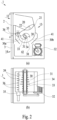
- (1) designates a machine for shredding inorganic materials according to the invention.
- said machine (1) has compact dimensions and a design suitable for a home installation or in small commercial or artisan businesses, in which solid inorganic waste is produced.
- the machine (1) is equipped with:
- Both doors (2, 3) are equipped with an electric lock (not shown) that keeps them closed during the operation of the machine (1).
- Said machine (1) includes:
- These fifth means include:
- Said first loading means (12) comprise said first door (2) which allows access to a large area (20), in which there is a sensor (not shown), to detect the presence of materials to be treated, said the loading area (20) being limited downwards by a movable element (21), rotatable around a pin (22), which has the main function of regulating the flow of the materials to be treated.
- the element (21) has the sectional shape of an arc of circumference. This allows it to accommodate the materials to be treated in the concavity and to pour them easily into an underlying shredding chamber (30) by rotating around said pin (22).
- said mobile element (21) can be replaced by multiple mobile elements (not shown) designed to open the passage between the loading area (20) and the shredding chamber (30).
- Said second shredding means (13) comprise:
- the wall of said shredding chamber (30), made of wear-resistant steel, comprises:
- a plurality of openings is made, so as to obtain a sort of evacuation net (38), suitable for letting the shredded material through, acting as a sieve that allows only the fragments that have reached a predetermined size, said openings being able to have various shapes (for example round, square, etc.) and dimensions.
- the rake (35) is placed outside the shredding chamber (30), in correspondence with the main rotor (31) in order to interact with it. Said interaction occurs following a rotation of said rake (35) towards the main rotor (31) and the consequent insertion of the blades (36) of the rake (35) between the knives (33, 34) of the main rotor (31). Said insertion is made possible by suitable openings (39) made on the wall of the shredding chamber (30).
- the rake (35) can be placed inside the shredding chamber (30); in this case said minor knives are present (not shown) and no openings are necessary in the wall of said shredding chamber to allow the knives (36) of the rake (35) to pass.
- the rake (35) there are sensors, able to identify both its position with respect to the main rotor (31), and the presence of any loads interposed in the movement that excessively hinder its rotation, causing an increase in the absorption of incompatible electrical power. with the capacity of the power supply network.
- Said mobile element (21) can assume various positions, rotating around said pin (22):
- said movable element (21) also has an important safety function, as it prevents access by hand to the shredding chamber (30) since the deposition of the materials in the loading area (20) takes place with the mobile element (21) in the closed position.
- the mobile element (21) reduces the noise since, after the total discharge of the material present in the loading area (20) into the shredding chamber (30), it is arranged according to said third position so as to avoid the return of flakes towards the inlet and, being provided with suitable seals, also reduces the noise generated by crushing.
- the installation, inside the shredding chamber (30), of a suction system (not shown) of the dust that is generated in the shredding of some materials is provided.
- Said third unloading means (14), for the collection of the shredded materials comprise a jacket conveyor (41), positioned outside the shredding chamber (30).
- Said conveyor (41) is shaped in such a way as to receive the shredded material that comes out of the evacuation net (38) and to convey it towards a collection area, where a basket (42) is positioned.
- a level sensor (not shown) is positioned in the jacket (41) or in the basket (42) to detect the filling of the basket itself, to signal its status to an electronic control system.
- the operator After opening the upper door (2), the operator places the materials to be shredded in the loading area (20). These materials are collected in the concavity of the mobile element (21) ( FIG. 3a ). After loading, the upper door (2) is closed and the electric locks of both doors (2, 3) are activated.
- the mobile element (21) rotates gradually, preferably after the motor (32) has already been started with no load, in order to limit the current absorption at start-up.
- the rotation of the mobile element (21) around the pin (22) allows to open the passage between the loading area (20) and the shredding chamber (30), said rotation taking place with the necessary gradualness to avoid a too rapid insertion of the materials to be shredded. In this way, the power required by the system is limited and the use of lower power motors is made possible and, therefore, able to operate with the low electrical power installed in domestic users.
- the material falling into the shredding chamber (30) is thrown by the knives (33, 34) of the main rotor (31) against the walls of the shredding chamber (30) itself.
- the material circulates inside the shredding chamber (30) with a circular trajectory around the axis of the main rotor (31), passing several times between the blades of the main rotor (31) and those of the rake (35), breaking up further at each step.
- the circular trajectory causes it to be projected by centrifugal force against the walls of the shredding chamber (30); this fact allows the formation of said dynamic accumulation in the area (30a) of the shredding chamber (30) and facilitates the exit through the evacuation network (38), when the fragments have reached the desired size.
Landscapes
- Engineering & Computer Science (AREA)
- Food Science & Technology (AREA)
- Environmental & Geological Engineering (AREA)
- Crushing And Pulverization Processes (AREA)
- Disintegrating Or Milling (AREA)
Claims (9)
- Maschine (1) zum Zerkleinern anorganischer Abfälle, umfassend:- erste Lademittel (12), geeignet zum Aufnehmen der zu zerkleinernden Materialien und zum Einfüllen derselben in eine Zerkleinerungskammer (30);- zweite Zerkleinerungsmittel (13), angetrieben durch einen Motor (32), geeignet zum Zerkleinern der eingeführten Materialien;- dritte Entlademittel (14), die zum Sammeln der zerkleinerten Materialien bestimmt sind;- viertes elektronisches Mittel zur Steuerung des Maschinenbetriebs;- fünfte Mittel, die von den vierten elektronischen Mitteln gesteuert werden und geeignet sind, das auf den Motor (32) ausgeübte Widerstandsdrehmoment zu begrenzen, um eine Stromaufnahme zu vermeiden, die die Kapazität des Stromversorgungsnetzes übersteigt, wobei die fünften Mittel ein oder mehrere mobile Elemente umfassen (21), die in der Lage sind, Positionen einzunehmen, die es ermöglichen, dass die eingebrachten Materialien allmählich in die Zerkleinerungskammer (30) geschüttet werden, so dass der Motor (32) leer oder mit minimaler Last gestartet werden kann, wobei die fünften Mittel eine Vielzahl von Messern umfassen (33, 34, 36), die miteinander interagieren, um die Zerkleinerung der eingebrachten Materialien durchzuführen, wobei die Interaktion kontrolliert wird, um übermäßige Materialansammlungen zwischen den Messern (33, 34, 36) zu vermeiden und so das Paar zu verhindern Der Widerstand erzeugt aufgrund der Schneidwirkung eine Stromaufnahme durch den Motor (32), die größer ist als die Kapazität des Stromversorgungsnetzes.wobei die zweiten Zerkleinerungsmittel (13) die Zerkleinerungskammer (30) umfassen, in der sich ein Hauptrotor (31) befindet, der von einem Motor (32) angetrieben wird und mit einer Vielzahl von Messern (33, 34) versehen ist, die mit dem zusammenwirken Messer (36) eines Rechens (35), wobei der Rechen (35) beweglich ist, um die Messer (36) mit den Messern (33, 34) des Hauptrotors (31) in Wechselwirkung zu bringen, die Position des Rechens (35). ) in Bezug auf den Hauptrotor (31) einstellbar ist, um zu steuern, dass das Widerstandsdrehmoment aufgrund der Schneidwirkung der Messer eine Stromaufnahme durch den Motor (32) erzeugt, die die Kapazität des Stromversorgungsnetzes nicht überschreitet;und wobei die Mahlkammer (30) durch feste Wände begrenzt ist, die Folgendes umfassen:- einen ersten Abschnitt (30a), der im Wesentlichen kreisförmig ist und auf der Achse des Hauptrotors (31) zentriert ist;- einen zweiten Abschnitt (30b), der an den ersten Abschnitt (30a) anschließt und im Wesentlichen kreisförmig ist, jedoch einen größeren Radius als der vorherige aufweist, um den Abstand zwischen der Flugbahn der Enden der Messer (33) zu vergrößern, und die Wand der Zerkleinerungskammer (30);
und dadurch gekennzeichnet, dass- das bewegliche Element (21), das nach dem Einfüllen der zu behandelnden Materialien in die Zerkleinerungskammer (30) so angeordnet ist, dass es die Zerkleinerungskammer (30) verschließt;das bewegliche Element (21) dreht sich um einen Stift (22) und hat die Querschnittsform eines Umfangsbogens, so dass es das geladene Material in seiner Konkavität aufnimmt und:- Durch Drehen um den Stift (22) bis etwa 90° reguliert er den Fluss der in die darunter liegende Zerkleinerungskammer (30) einzufüllenden Materialien;- indem er sich um etwa 180° um den Stift (22) dreht, verschließt er den Durchgang zum Beschickungsbereich (20) vollständig und begrenzt so einen großen Bereich (30c) im Inneren der Zerkleinerungskammer (30), in den die von der Zentrifuge geschleuderten Materialien gelangen Durch die starke Rotation des Hauptrotors (31) neigen sie dazu, sich dynamisch anzusammeln und durch die Schwerkraft in den darunter liegenden Bereich zu fallen, wo sie erneut von den Messern (33, 34) des Hauptrotors (31) erfasst werden, um zwischen den Messern (36) des Rechens (35) hindurchzugehen und einer erneuten Zerkleinerung zu unterziehen, wobei die Bildung dieser dynamischen Ansammlung durch Regulierung des Materialflusses zwischen den Messern (33, 34, 36) verhindert, dass der vom Motor aufgenommene Strom (32) von höher auf die Kapazität des Stromversorgungsnetzes. - Maschine (1) zum Zerkleinern anorganischer Abfälle nach Anspruch 1, dadurch gekennzeichnet, dass die ersten Lademittel (12) eine erste Tür (2) umfassen, die den Zugang zu einem Ladebereich (20) zum Einlegen der zu füllenden Materialien ermöglicht behandelt, wobei die Ladefläche (20) durch das eine oder die mehreren mobilen Elemente (21) begrenzt wird.
- Maschine (1) zum Zerkleinern anorganischer Abfälle nach Anspruch 2, dadurch gekennzeichnet, dass die Tür (2) mit einem elektrischen Schloss ausgestattet ist, das sich automatisch schließen kann, wenn die Maschine (1) in Betrieb ist.
- Maschine (1) zum Zerkleinern anorganischer Abfälle nach Anspruch 2, dadurch gekennzeichnet, dass sich innerhalb des Ladebereichs (20) ein Sensor befindet, der das Vorhandensein von zu behandelnden Materialien erkennen kann.
- Maschine (1) zum Zerkleinern anorganischer Abfälle nach Anspruch 1, dadurch gekennzeichnet, dass im unteren Teil der Wand der Zerkleinerungskammer (30) mehrere Öffnungen angebracht sind, um so eine Art Evakuierungsnetzwerk zu erhalten (38), das das zerkleinerte Material passieren lässt und wie ein Sieb wirkt, das nur die Bruchstücke durchlässt, die eine vorgegebene Größe erreicht haben.
- Maschine (1) zum Zerkleinern anorganischer Abfälle nach Anspruch 1, dadurch gekennzeichnet, dass die dritten Entlademittel (14), die zum Sammeln der zerkleinerten Materialien geeignet sind, einen Mantelförderer (41) umfassen, der außerhalb der Zerkleinerungskammer positioniert ist (30) und in Übereinstimmung mit dem Evakuierungsnetz (38), wobei der Förderer (41) so geformt ist, dass er das zerkleinerte Material, das aus dem Evakuierungsnetz (38) kommt, aufnimmt und es zu einem Sammelbereich befördert, wo ein Korb ( 42) positioniert ist.
- Maschine (1) zum Zerkleinern anorganischer Abfälle nach mindestens einem der Ansprüche 1 bis 6, dadurch gekennzeichnet, dass das Vorhandensein eines oder mehrerer Sensoren an dem Rechen (35) vorgesehen ist, die geeignet sind, seine Position in Bezug auf den Rechen (35) zu identifizieren zum Hauptrotor (31) und das Vorhandensein von Lasten im Uhrwerk, die seine Drehung übermäßig behindern, was zu einer Erhöhung der Stromaufnahme führt, die nicht mit der Kapazität des Stromversorgungsnetzes vereinbar ist.
- Verfahren zur Begrenzung der zum Antrieb einer Zerkleinerungsmaschine (1) für anorganische Stoffe erforderlichen Leistung nach mindestens einem der Ansprüche 1 bis 7, geeignet zur Begrenzung der Entstehung von Widerstandspaaren aufgrund der Zerkleinerungswirkung, die eine Stromaufnahme erfordern die die Kapazität des Stromversorgungsnetzes übersteigt, wobei die Begrenzung der Entwicklung resistenter Paare aufgrund des Zerkleinerungsvorgangs durch ein allmähliches Einfüllen der zu behandelnden Materialien in die Zerkleinerungskammer (30) erreicht wird, wodurch ein Anfahren ermöglicht wird bei Leerlauf oder bei minimaler Belastung des Motors (32), wobei die Allmählichkeit durch eine allmähliche Drehung des beweglichen Elements (21) erreicht wird, die durch das vierte elektronische Mittel gesteuert wird.
- Verfahren zur Begrenzung der zum Antrieb einer Zerkleinerungsmaschine (1) für anorganische Stoffe erforderlichen Leistung nach Anspruch 8, geeignet zur Begrenzung der Entstehung von Widerstandsmomenten aufgrund der Zerkleinerungswirkung, die eine über die Kapazität hinausgehende Stromaufnahme aus dem Vorrat erfordern Netzwerk, das als Begrenzung der Entwicklung von Widerstandspaaren aufgrund der Zerkleinerungswirkung bezeichnet wird und durch ein Zurückziehen der Messer (36) des Rechens (35) im Falle von überschüssigem Material, das sich zwischen den Messern (36, 37) angesammelt hat, umgesetzt wird Rechen (35) und die Messer (33, 34) des Hauptrotors (31).
Applications Claiming Priority (2)
| Application Number | Priority Date | Filing Date | Title |
|---|---|---|---|
| IT102020000011764A IT202000011764A1 (it) | 2020-05-20 | 2020-05-20 | Macchina e metodo per la triturazione di rifiuti inorganici |
| PCT/IT2021/050100 WO2021234744A1 (en) | 2020-05-20 | 2021-04-09 | Machine and method for shredding inorganic waste |
Publications (2)
| Publication Number | Publication Date |
|---|---|
| EP4153367A1 EP4153367A1 (de) | 2023-03-29 |
| EP4153367B1 true EP4153367B1 (de) | 2024-07-31 |
Family
ID=72086967
Family Applications (1)
| Application Number | Title | Priority Date | Filing Date |
|---|---|---|---|
| EP21723923.5A Active EP4153367B1 (de) | 2020-05-20 | 2021-04-09 | Vorrichtung und verfahren zur zerkleinerung von anorganischen abfällen |
Country Status (5)
| Country | Link |
|---|---|
| US (1) | US20230182147A1 (de) |
| EP (1) | EP4153367B1 (de) |
| ES (1) | ES2991376T3 (de) |
| IT (1) | IT202000011764A1 (de) |
| WO (1) | WO2021234744A1 (de) |
Family Cites Families (9)
| Publication number | Priority date | Publication date | Assignee | Title |
|---|---|---|---|---|
| GB2024654A (en) * | 1978-07-05 | 1980-01-16 | Metal Box Co Ltd | Dealing with intractable material in a shredding machine |
| US4844363A (en) * | 1987-07-06 | 1989-07-04 | Shredding Systems, Inc. | Hopper ram for shredder |
| IT1227937B (it) * | 1988-07-01 | 1991-05-14 | Parolisi Massimo E Di Cerbo Fu | Macchina atta a ricevere i rifiuti urbani direttamente nelle abitazioni e ad inviarli attraverso apposite tubazioni ai depositi di raccolta dopo averli compattati e ridotti in piccoli pezzi |
| DE8905352U1 (de) * | 1988-11-03 | 1989-12-14 | Hofmann, Karl | Vorrichtung zum Entsorgen von Dosen |
| US4917310A (en) * | 1989-02-27 | 1990-04-17 | Sorain Cecchini Recovery, Incorporated | Processing apparatus for solid refuse |
| JP3226107B2 (ja) * | 1991-07-22 | 2001-11-05 | 株式会社栗本鐵工所 | ロータ剪断式破砕機 |
| IT1247548B (it) * | 1994-05-18 | 1994-12-19 | Alfa Srl | Trituratore a selezione di materiali con compattatore |
| US20110108648A1 (en) * | 2009-11-06 | 2011-05-12 | Hammermills International, LLC | Feeder For Material Shredder |
| DE102015003991A1 (de) * | 2015-03-30 | 2016-10-06 | Weima Maschinenbau Gmbh | Vorrichtung zum Zerkleinern von Material, insbesondere von medizinischem Abfallmaterial |
-
2020
- 2020-05-20 IT IT102020000011764A patent/IT202000011764A1/it unknown
-
2021
- 2021-04-09 EP EP21723923.5A patent/EP4153367B1/de active Active
- 2021-04-09 WO PCT/IT2021/050100 patent/WO2021234744A1/en not_active Ceased
- 2021-04-09 US US17/926,445 patent/US20230182147A1/en not_active Abandoned
- 2021-04-09 ES ES21723923T patent/ES2991376T3/es active Active
Also Published As
| Publication number | Publication date |
|---|---|
| IT202000011764A1 (it) | 2020-08-20 |
| US20230182147A1 (en) | 2023-06-15 |
| WO2021234744A1 (en) | 2021-11-25 |
| EP4153367A1 (de) | 2023-03-29 |
| ES2991376T3 (es) | 2024-12-03 |
Similar Documents
| Publication | Publication Date | Title |
|---|---|---|
| US3987970A (en) | Centrifugal mill | |
| US4557421A (en) | Paper disintegrator and method of operating same | |
| US8028940B2 (en) | Residential waste volume reduction arrangements | |
| US3703970A (en) | Apparatus for treating waste material | |
| US3595488A (en) | Method of waste treatment | |
| CA2120692C (en) | Comminuting machine with comminution grates | |
| US5213273A (en) | Hammer mill | |
| KR101787666B1 (ko) | 폐기물 파쇄장치 | |
| KR102482717B1 (ko) | 폐기물 관리 및 재생 시스템 | |
| KR20170057663A (ko) | 재활용 폐기물 분쇄장치 | |
| EP0990466B1 (de) | Verfahren zur Herstellung von Glassand und System dafür | |
| US4917310A (en) | Processing apparatus for solid refuse | |
| CN112041083B (zh) | 具有改进的安全性的用于金属材料的可移动式切碎机 | |
| KR101636540B1 (ko) | 수로용 고효율 협잡물파쇄이송시스템 | |
| US20230182147A1 (en) | Machine and method for shredding inorganic waste | |
| WO2021234743A1 (en) | Machine for shredding inorganic waste | |
| JP2017131832A (ja) | 二軸剪断式破砕機 | |
| US4903904A (en) | Comminuting device for turnings | |
| US3713594A (en) | Waste treatment system | |
| EP2389250A1 (de) | Zerkleinerungsmühle und entsprechendes zerkleinerungsverfahren | |
| KR100973074B1 (ko) | 음식물류 폐기물 순간분쇄기 | |
| JP7345862B2 (ja) | 破砕装置 | |
| EP2389249B1 (de) | Zerkleinerungsmühle und entsprechendes zerkleinerungsverfahren | |
| KR102390182B1 (ko) | 일체형파쇄선별기 | |
| CN102245308A (zh) | 装备有相对于供料槽轴线倾斜的转子的小型搅碎机 |
Legal Events
| Date | Code | Title | Description |
|---|---|---|---|
| STAA | Information on the status of an ep patent application or granted ep patent |
Free format text: STATUS: UNKNOWN |
|
| STAA | Information on the status of an ep patent application or granted ep patent |
Free format text: STATUS: THE INTERNATIONAL PUBLICATION HAS BEEN MADE |
|
| PUAI | Public reference made under article 153(3) epc to a published international application that has entered the european phase |
Free format text: ORIGINAL CODE: 0009012 |
|
| STAA | Information on the status of an ep patent application or granted ep patent |
Free format text: STATUS: REQUEST FOR EXAMINATION WAS MADE |
|
| 17P | Request for examination filed |
Effective date: 20221117 |
|
| AK | Designated contracting states |
Kind code of ref document: A1 Designated state(s): AL AT BE BG CH CY CZ DE DK EE ES FI FR GB GR HR HU IE IS IT LI LT LU LV MC MK MT NL NO PL PT RO RS SE SI SK SM TR |
|
| DAV | Request for validation of the european patent (deleted) | ||
| DAX | Request for extension of the european patent (deleted) | ||
| GRAP | Despatch of communication of intention to grant a patent |
Free format text: ORIGINAL CODE: EPIDOSNIGR1 |
|
| STAA | Information on the status of an ep patent application or granted ep patent |
Free format text: STATUS: GRANT OF PATENT IS INTENDED |
|
| INTG | Intention to grant announced |
Effective date: 20240304 |
|
| GRAS | Grant fee paid |
Free format text: ORIGINAL CODE: EPIDOSNIGR3 |
|
| GRAA | (expected) grant |
Free format text: ORIGINAL CODE: 0009210 |
|
| STAA | Information on the status of an ep patent application or granted ep patent |
Free format text: STATUS: THE PATENT HAS BEEN GRANTED |
|
| AK | Designated contracting states |
Kind code of ref document: B1 Designated state(s): AL AT BE BG CH CY CZ DE DK EE ES FI FR GB GR HR HU IE IS IT LI LT LU LV MC MK MT NL NO PL PT RO RS SE SI SK SM TR |
|
| REG | Reference to a national code |
Ref country code: CH Ref legal event code: EP Ref country code: GB Ref legal event code: FG4D |
|
| REG | Reference to a national code |
Ref country code: DE Ref legal event code: R096 Ref document number: 602021016475 Country of ref document: DE |
|
| REG | Reference to a national code |
Ref country code: IE Ref legal event code: FG4D |
|
| REG | Reference to a national code |
Ref country code: LT Ref legal event code: MG9D |
|
| REG | Reference to a national code |
Ref country code: ES Ref legal event code: FG2A Ref document number: 2991376 Country of ref document: ES Kind code of ref document: T3 Effective date: 20241203 |
|
| REG | Reference to a national code |
Ref country code: NL Ref legal event code: MP Effective date: 20240731 |
|
| PG25 | Lapsed in a contracting state [announced via postgrant information from national office to epo] |
Ref country code: PT Free format text: LAPSE BECAUSE OF FAILURE TO SUBMIT A TRANSLATION OF THE DESCRIPTION OR TO PAY THE FEE WITHIN THE PRESCRIBED TIME-LIMIT Effective date: 20241202 |
|
| REG | Reference to a national code |
Ref country code: AT Ref legal event code: MK05 Ref document number: 1708002 Country of ref document: AT Kind code of ref document: T Effective date: 20240731 |
|
| PG25 | Lapsed in a contracting state [announced via postgrant information from national office to epo] |
Ref country code: PT Free format text: LAPSE BECAUSE OF FAILURE TO SUBMIT A TRANSLATION OF THE DESCRIPTION OR TO PAY THE FEE WITHIN THE PRESCRIBED TIME-LIMIT Effective date: 20241202 |
|
| PG25 | Lapsed in a contracting state [announced via postgrant information from national office to epo] |
Ref country code: NO Free format text: LAPSE BECAUSE OF FAILURE TO SUBMIT A TRANSLATION OF THE DESCRIPTION OR TO PAY THE FEE WITHIN THE PRESCRIBED TIME-LIMIT Effective date: 20241031 |
|
| PG25 | Lapsed in a contracting state [announced via postgrant information from national office to epo] |
Ref country code: NL Free format text: LAPSE BECAUSE OF FAILURE TO SUBMIT A TRANSLATION OF THE DESCRIPTION OR TO PAY THE FEE WITHIN THE PRESCRIBED TIME-LIMIT Effective date: 20240731 Ref country code: PL Free format text: LAPSE BECAUSE OF FAILURE TO SUBMIT A TRANSLATION OF THE DESCRIPTION OR TO PAY THE FEE WITHIN THE PRESCRIBED TIME-LIMIT Effective date: 20240731 Ref country code: FI Free format text: LAPSE BECAUSE OF FAILURE TO SUBMIT A TRANSLATION OF THE DESCRIPTION OR TO PAY THE FEE WITHIN THE PRESCRIBED TIME-LIMIT Effective date: 20240731 Ref country code: GR Free format text: LAPSE BECAUSE OF FAILURE TO SUBMIT A TRANSLATION OF THE DESCRIPTION OR TO PAY THE FEE WITHIN THE PRESCRIBED TIME-LIMIT Effective date: 20241101 |
|
| PG25 | Lapsed in a contracting state [announced via postgrant information from national office to epo] |
Ref country code: BG Free format text: LAPSE BECAUSE OF FAILURE TO SUBMIT A TRANSLATION OF THE DESCRIPTION OR TO PAY THE FEE WITHIN THE PRESCRIBED TIME-LIMIT Effective date: 20240731 |
|
| PG25 | Lapsed in a contracting state [announced via postgrant information from national office to epo] |
Ref country code: LV Free format text: LAPSE BECAUSE OF FAILURE TO SUBMIT A TRANSLATION OF THE DESCRIPTION OR TO PAY THE FEE WITHIN THE PRESCRIBED TIME-LIMIT Effective date: 20240731 |
|
| PG25 | Lapsed in a contracting state [announced via postgrant information from national office to epo] |
Ref country code: IS Free format text: LAPSE BECAUSE OF FAILURE TO SUBMIT A TRANSLATION OF THE DESCRIPTION OR TO PAY THE FEE WITHIN THE PRESCRIBED TIME-LIMIT Effective date: 20241130 Ref country code: AT Free format text: LAPSE BECAUSE OF FAILURE TO SUBMIT A TRANSLATION OF THE DESCRIPTION OR TO PAY THE FEE WITHIN THE PRESCRIBED TIME-LIMIT Effective date: 20240731 |
|
| PG25 | Lapsed in a contracting state [announced via postgrant information from national office to epo] |
Ref country code: HR Free format text: LAPSE BECAUSE OF FAILURE TO SUBMIT A TRANSLATION OF THE DESCRIPTION OR TO PAY THE FEE WITHIN THE PRESCRIBED TIME-LIMIT Effective date: 20240731 |
|
| PG25 | Lapsed in a contracting state [announced via postgrant information from national office to epo] |
Ref country code: RS Free format text: LAPSE BECAUSE OF FAILURE TO SUBMIT A TRANSLATION OF THE DESCRIPTION OR TO PAY THE FEE WITHIN THE PRESCRIBED TIME-LIMIT Effective date: 20241031 |
|
| PG25 | Lapsed in a contracting state [announced via postgrant information from national office to epo] |
Ref country code: RS Free format text: LAPSE BECAUSE OF FAILURE TO SUBMIT A TRANSLATION OF THE DESCRIPTION OR TO PAY THE FEE WITHIN THE PRESCRIBED TIME-LIMIT Effective date: 20241031 Ref country code: PL Free format text: LAPSE BECAUSE OF FAILURE TO SUBMIT A TRANSLATION OF THE DESCRIPTION OR TO PAY THE FEE WITHIN THE PRESCRIBED TIME-LIMIT Effective date: 20240731 Ref country code: NO Free format text: LAPSE BECAUSE OF FAILURE TO SUBMIT A TRANSLATION OF THE DESCRIPTION OR TO PAY THE FEE WITHIN THE PRESCRIBED TIME-LIMIT Effective date: 20241031 Ref country code: NL Free format text: LAPSE BECAUSE OF FAILURE TO SUBMIT A TRANSLATION OF THE DESCRIPTION OR TO PAY THE FEE WITHIN THE PRESCRIBED TIME-LIMIT Effective date: 20240731 Ref country code: LV Free format text: LAPSE BECAUSE OF FAILURE TO SUBMIT A TRANSLATION OF THE DESCRIPTION OR TO PAY THE FEE WITHIN THE PRESCRIBED TIME-LIMIT Effective date: 20240731 Ref country code: IS Free format text: LAPSE BECAUSE OF FAILURE TO SUBMIT A TRANSLATION OF THE DESCRIPTION OR TO PAY THE FEE WITHIN THE PRESCRIBED TIME-LIMIT Effective date: 20241130 Ref country code: HR Free format text: LAPSE BECAUSE OF FAILURE TO SUBMIT A TRANSLATION OF THE DESCRIPTION OR TO PAY THE FEE WITHIN THE PRESCRIBED TIME-LIMIT Effective date: 20240731 Ref country code: GR Free format text: LAPSE BECAUSE OF FAILURE TO SUBMIT A TRANSLATION OF THE DESCRIPTION OR TO PAY THE FEE WITHIN THE PRESCRIBED TIME-LIMIT Effective date: 20241101 Ref country code: FI Free format text: LAPSE BECAUSE OF FAILURE TO SUBMIT A TRANSLATION OF THE DESCRIPTION OR TO PAY THE FEE WITHIN THE PRESCRIBED TIME-LIMIT Effective date: 20240731 Ref country code: BG Free format text: LAPSE BECAUSE OF FAILURE TO SUBMIT A TRANSLATION OF THE DESCRIPTION OR TO PAY THE FEE WITHIN THE PRESCRIBED TIME-LIMIT Effective date: 20240731 Ref country code: AT Free format text: LAPSE BECAUSE OF FAILURE TO SUBMIT A TRANSLATION OF THE DESCRIPTION OR TO PAY THE FEE WITHIN THE PRESCRIBED TIME-LIMIT Effective date: 20240731 |
|
| PG25 | Lapsed in a contracting state [announced via postgrant information from national office to epo] |
Ref country code: SM Free format text: LAPSE BECAUSE OF FAILURE TO SUBMIT A TRANSLATION OF THE DESCRIPTION OR TO PAY THE FEE WITHIN THE PRESCRIBED TIME-LIMIT Effective date: 20240731 Ref country code: RO Free format text: LAPSE BECAUSE OF FAILURE TO SUBMIT A TRANSLATION OF THE DESCRIPTION OR TO PAY THE FEE WITHIN THE PRESCRIBED TIME-LIMIT Effective date: 20240731 Ref country code: DK Free format text: LAPSE BECAUSE OF FAILURE TO SUBMIT A TRANSLATION OF THE DESCRIPTION OR TO PAY THE FEE WITHIN THE PRESCRIBED TIME-LIMIT Effective date: 20240731 |
|
| PG25 | Lapsed in a contracting state [announced via postgrant information from national office to epo] |
Ref country code: EE Free format text: LAPSE BECAUSE OF FAILURE TO SUBMIT A TRANSLATION OF THE DESCRIPTION OR TO PAY THE FEE WITHIN THE PRESCRIBED TIME-LIMIT Effective date: 20240731 |
|
| PG25 | Lapsed in a contracting state [announced via postgrant information from national office to epo] |
Ref country code: CZ Free format text: LAPSE BECAUSE OF FAILURE TO SUBMIT A TRANSLATION OF THE DESCRIPTION OR TO PAY THE FEE WITHIN THE PRESCRIBED TIME-LIMIT Effective date: 20240731 |
|
| PG25 | Lapsed in a contracting state [announced via postgrant information from national office to epo] |
Ref country code: SK Free format text: LAPSE BECAUSE OF FAILURE TO SUBMIT A TRANSLATION OF THE DESCRIPTION OR TO PAY THE FEE WITHIN THE PRESCRIBED TIME-LIMIT Effective date: 20240731 |
|
| REG | Reference to a national code |
Ref country code: DE Ref legal event code: R097 Ref document number: 602021016475 Country of ref document: DE |
|
| PLBE | No opposition filed within time limit |
Free format text: ORIGINAL CODE: 0009261 |
|
| STAA | Information on the status of an ep patent application or granted ep patent |
Free format text: STATUS: NO OPPOSITION FILED WITHIN TIME LIMIT |
|
| 26N | No opposition filed |
Effective date: 20250501 |
|
| PGFP | Annual fee paid to national office [announced via postgrant information from national office to epo] |
Ref country code: DE Payment date: 20250429 Year of fee payment: 5 |
|
| PGFP | Annual fee paid to national office [announced via postgrant information from national office to epo] |
Ref country code: GB Payment date: 20250428 Year of fee payment: 5 Ref country code: ES Payment date: 20250505 Year of fee payment: 5 |
|
| PGFP | Annual fee paid to national office [announced via postgrant information from national office to epo] |
Ref country code: FR Payment date: 20250425 Year of fee payment: 5 |
|
| PG25 | Lapsed in a contracting state [announced via postgrant information from national office to epo] |
Ref country code: SE Free format text: LAPSE BECAUSE OF FAILURE TO SUBMIT A TRANSLATION OF THE DESCRIPTION OR TO PAY THE FEE WITHIN THE PRESCRIBED TIME-LIMIT Effective date: 20240731 |
|
| REG | Reference to a national code |
Ref country code: CH Ref legal event code: H13 Free format text: ST27 STATUS EVENT CODE: U-0-0-H10-H13 (AS PROVIDED BY THE NATIONAL OFFICE) Effective date: 20251125 |
|
| PG25 | Lapsed in a contracting state [announced via postgrant information from national office to epo] |
Ref country code: LU Free format text: LAPSE BECAUSE OF NON-PAYMENT OF DUE FEES Effective date: 20250409 |
|
| PG25 | Lapsed in a contracting state [announced via postgrant information from national office to epo] |
Ref country code: MC Free format text: LAPSE BECAUSE OF FAILURE TO SUBMIT A TRANSLATION OF THE DESCRIPTION OR TO PAY THE FEE WITHIN THE PRESCRIBED TIME-LIMIT Effective date: 20240731 |
|
| REG | Reference to a national code |
Ref country code: BE Ref legal event code: MM Effective date: 20250430 |
|
| PG25 | Lapsed in a contracting state [announced via postgrant information from national office to epo] |
Ref country code: BE Free format text: LAPSE BECAUSE OF NON-PAYMENT OF DUE FEES Effective date: 20250430 |
|
| PG25 | Lapsed in a contracting state [announced via postgrant information from national office to epo] |
Ref country code: CH Free format text: LAPSE BECAUSE OF NON-PAYMENT OF DUE FEES Effective date: 20250430 |
|
| PG25 | Lapsed in a contracting state [announced via postgrant information from national office to epo] |
Ref country code: IE Free format text: LAPSE BECAUSE OF NON-PAYMENT OF DUE FEES Effective date: 20250409 |
|
| PGFP | Annual fee paid to national office [announced via postgrant information from national office to epo] |
Ref country code: IT Payment date: 20260310 Year of fee payment: 6 |