EP4153003B1 - Rucksack und umhängetasche kombiniert - Google Patents
Rucksack und umhängetasche kombiniert Download PDFInfo
- Publication number
- EP4153003B1 EP4153003B1 EP21728497.5A EP21728497A EP4153003B1 EP 4153003 B1 EP4153003 B1 EP 4153003B1 EP 21728497 A EP21728497 A EP 21728497A EP 4153003 B1 EP4153003 B1 EP 4153003B1
- Authority
- EP
- European Patent Office
- Prior art keywords
- strap
- bag
- loops
- storage bin
- opposite sides
- Prior art date
- Legal status (The legal status is an assumption and is not a legal conclusion. Google has not performed a legal analysis and makes no representation as to the accuracy of the status listed.)
- Active
Links
Images


Classifications
-
- A—HUMAN NECESSITIES
- A45—HAND OR TRAVELLING ARTICLES
- A45F—TRAVELLING OR CAMP EQUIPMENT: SACKS OR PACKS CARRIED ON THE BODY
- A45F4/00—Travelling or camp articles which may be converted into other articles or into objects for other use; Sacks or packs carried on the body and convertible into other articles or into objects for other use
- A45F4/02—Sacks or packs convertible into other articles or into objects for other use
-
- A—HUMAN NECESSITIES
- A45—HAND OR TRAVELLING ARTICLES
- A45F—TRAVELLING OR CAMP EQUIPMENT: SACKS OR PACKS CARRIED ON THE BODY
- A45F3/00—Travelling or camp articles; Sacks or packs carried on the body
- A45F3/04—Sacks or packs carried on the body by means of two straps passing over the two shoulders
-
- A—HUMAN NECESSITIES
- A45—HAND OR TRAVELLING ARTICLES
- A45F—TRAVELLING OR CAMP EQUIPMENT: SACKS OR PACKS CARRIED ON THE BODY
- A45F3/00—Travelling or camp articles; Sacks or packs carried on the body
- A45F3/02—Sacks or packs carried on the body by means of one strap passing over the shoulder
-
- A—HUMAN NECESSITIES
- A45—HAND OR TRAVELLING ARTICLES
- A45F—TRAVELLING OR CAMP EQUIPMENT: SACKS OR PACKS CARRIED ON THE BODY
- A45F4/00—Travelling or camp articles which may be converted into other articles or into objects for other use; Sacks or packs carried on the body and convertible into other articles or into objects for other use
- A45F4/02—Sacks or packs convertible into other articles or into objects for other use
- A45F2004/023—Sacks or packs convertible into other articles or into objects for other use into articles covered by groups A45F3/00 - A45F3/15
Definitions
- the present disclosure relates to a bag, which can transform easily from a rucksack to a shoulder bag and vice versa.
- Wearing a shoulder bag obstructs certain movements or exercises, for example the exercise of riding a bike.
- the shoulder bag may slide down the back of the user and may end up hanging down from the neck and arm obstructing the movement of the legs.
- wearing a rucksack may be associated with another image than the user want to achieve for example it may look less professional than a shoulder bag as it may be associated with schoolchildren or hikers rather than professional business people. For example, if someone is attending a professional business meeting, it may look more professional to bring a shoulder bag to a meeting, rather than a rucksack.
- fashionable teens or other groups which may be concerned about their appearance, may be reluctant to wear a rucksack.
- WO2015150878 discloses a transformable rucksack/shoulder bag with one strap. Both ends of the strap is attached on one side of the bag. In both rucksack configuration and shoulder bag configuration the strap only in contact with the same, one side of the bag.
- DE10055165 discloses a transformable rucksack/shoulder bag in which both ends of a strap is attached on one side of the bag. In the shoulder bag configuration, the strap is led straight across the top-side of the bag.
- WO2015147759 discloses a transformable rucksack/shoulder bag comprising a strap and four attachment members along the circumference of the bag, allowing the transformation by the number of attachment members used.
- US5415332 discloses a multimode traveling bag that can be carried as a hand-carrying bag, a backpack, a shoulder bag, or over the head bag.
- the slidable engagements of the presently disclosed bag may function as to lead the strap around the bag in a specific manner.
- the strap may be led through the slidable engagements in order to support a given configuration of the strap.
- the slidable engagements may allow the strap to move freely or almost freely, for example with some amount of friction, through these slidable engagements. If the bag comprises a strap which is longer than necessary to tightly encircle the bag in the desired configuration, the slidable engagements may allow that the access part of the strap can be moved to a different part of the strap configuration encircling the bag.
- access length of the strap in one part of the strap configuration may result in the strap being able to be used as a shoulder bag strap and by leading the access strap via the slidable engagements to other parts of the strap configuration, the access strap length may be used as straps for a rucksack.
- the slidable engagements may be provided in the form of loops.
- the bag comprises a storage bin having two opposite sides; a single continuous strap encircling the storage bin, wherein the ends of the strap are attached to the storage bin on each of the opposite sides at predefined attachment points; and at least four loops attached to the storage bin, wherein the strap is led through each of said loops such that the strap may slide through the loops.
- the attachment points and the four loops are distributed such that the bag has at least two configurations: a first configuration wherein one of the attachment points and three of the loops define carrying points for two shoulder straps such that the bag is configured for use as a rucksack, and a second configuration wherein the strap extends diagonally across a top part of the storage bin between two of the loops located on the opposite sides, wherein the bag may be carried in the strap extending diagonally across the top part, such that the bag is configured for use as a shoulder bag.
- Carrying points should be understood as termination points of the shoulder strap(s), said shoulder strap(s) being defined by one or more strap sections in the two configurations of the bag, once the encircling strap is pulled into the desired configuration.
- the first strap section (14) and the second strap section (18) may define two shoulder straps of the bag.
- one of said carrying points is preferably a fixed attachment point and the remaining three carrying points are defined by the loops.
- the presently disclosed bag may be worn as a rucksack, as shown in Figure 1A or as a shoulder bag as shown in Figure 1B .
- An example of the transformation mechanism between the two is illustrated in Figure 2 .
- the strap and slidable engagements of the presently disclosed bag are preferably distributed such that the opposite sides are 180 degrees rotation symmetric.
- One example of such a distribution is illustrated in Figure 3 .
- the opposite sides of the bin 1 and 2 are equivalent upon 180 degrees rotation around a vertical axis centred in the bag, strap sections 14 and 18 are equivalent to 12 and 16 upon the 180 degrees rotation.
- the strap attachments 11 and 19 are equivalent upon the 180 degrees rotation.
- the 180 degrees rotational symmetry corresponds to a 2-fold rotational symmetry with respect to a central vertical axis running parallel with the two opposite sides. This ensures that any of the opposite sides of the storage bin can face the back of a user in the rucksack configuration.
- the strap used for the presently disclosed bag may be a rope but more preferred a webbing.
- Webbing is a strong fabric woven as a flat strip or tube of varying width and fibres.
- Webbing may be made of hemp, cotton or linen, but preferred here is synthetic fibres, such as nylon, polypropylene or polyester, most preferred is webbing made from recycled plastics.
- Webbing is both light and strong, with high breaking strength.
- flat webbing is preferred over tubular webbing as it is more comfortable when wearing.
- the width of the strap may be between 1 and 10 cm, preferably between 2 and 6 cm, preferably between 3 and 5 cm, such as around 4 cm.
- the thickness of the strap is preferably less than 10 mm, more preferably less than 5 mm, even more preferably less than 2 mm, most preferably less than 1.2 mm, such as around 1 mm thickness.
- an 1.5 inch flat webbing of 0.04 inch thickness can be used, corresponding to a webbing width of 3.8 cm and 1 mm thickness.
- the bag is configured such that each of said opposite sides can face the back of a user during rucksack use. This enables the user to lead the strap into rucksack configuration on either of the opposite sides of the bin. This means that the bag can be worn as a rucksack regardless of which side of the two opposite sides is facing the user. The straps can be pulled out and the bag can be worn as a rucksack on either side. This can further increase the speed of which the bag is transformed into a rucksack as the user will not have to turn the bag to the side on which the rucksack transformation is possible, if for example the user by chance should grab the bag on the opposite side.
- FIG. 3 An additional feature of this is the possibility to have different colours or designs on each side of the bag, if one wants to be able to change the look of the rucksack.
- the strap is encircling the bag in a manner as the one illustrated in Figure 3 , one may pull the sections 14 and 18 and arrive at the rucksack mode as shown in Figure 4 .
- the purpose of Figure 3 is to illustrate the overall configuration of the strap in the present example and hence the access strap length necessary to transform the bag from the one shown in Figure 3 to Figure 4 is not shown in Figure 3 .
- the strap would hence have to be longer than shown in Figure 3 , but in order to more clearly illustrate the path of the strap, the strap of Figure 3 has been shown as tightly encircling the bag.
- the shoulder bag may be transformed into a rucksack by pulling the parts of the strap configured for being in contact with the shoulders during rucksack use. In this example that would be strap sections 14 and 18 or 12 and 16 depending on which side of the bag should face the back of the user.
- the rucksack mode strap section 15 may be tightly following the top part of the bin. If the bin opening, such as by a zipper, is situated on this top part, it may further make it more difficult for pickpockets to enter the bag in rucksack mode. If the bag is configured such that each of said opposite sides can face the back of a user during rucksack use, the rucksack mode may be configured so that one of the strap end attachments and three of the slidable engagements on each opposite sides define four carrying positions of a rucksack, such that each of said opposite sides can face the back of a user during rucksack use.
- the opposite sides may have a four-cornered shape, the opposite sides may for example be squares or rectangles.
- the shape and dimensions may be so that it perfectly fit a laptop computer or a compendium of A4 papers.
- the bag may also have other shapes or dimensions which may depend on the purpose of the specific bag. For example if it is a laptop bag, a bag for luggage or a bag for small personal items.
- each strap end attachment and slidable engagement is placed adjacent to a corner of the opposite sides.
- the strap attachment By placing the strap attachment in the proximity to the corner, as shown at 11 and 19 in Figure 3-5 , the strap can be led through the slidable engagements likewise placed in the proximity to the corners, and the path of the strap will then be close to the edges of the bag as shown in Figs. 3-5 .
- the strap can be at a comfortable position for having the bag in rucksack mode, as illustrated by the two parts of the strap 14 and 18 in Figure. 4 .
- the two parts of the strap 14 and 18 may hence be placed at a distance that suits the distance between the shoulders on an average person. This distance can be smaller if the bag is made for a child.
- the slidable engagement will ensure the position at two corner positions on opposite sides of the bin in proper places for the bag to be carried as a shoulder bag.
- the diagonally positioning of the slidable engagements 20 and 21 further ensures that the bag is lifted in a symmetric manner so that the bag will balance in a harmonic manner, hanging straight downwards. This is an advantage compared to bags in which the carrying points of the shoulder bag mode is on the same side of the bag. In such cases, the bag would tilt slightly forward when lifted, due to the weight of the bag. This will be a less comfortable and may be somewhat odd looking.
- the positions 20 and 21 in Figure 3-5 may be placed on the two opposite sides of the bin, or on the top part of the bin close to the edges between the two opposite sides and top part, or it may be placed on the edges between the opposite sides and the top part of the bin, for example if they are fastened by including the slidable engagements in the hem between the different parts of the bin.
- Each strap end attachment may be placed at a diagonal distance to a corner.
- the fixation of the strap may for instance be at the two diagonal corners 11 and 19 opposite to the two diagonal corners having the slidable engagements 20 and 21 as shown in Figure 3-5 .
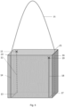
- the strap section 15, which can be pulled to become the shoulder bag strap, as shown in Figure 5 will be placed between the slidable engagements 20 and 21.
- the shoulder bag strap will connect the two diagonal corners opposite to the strap end attachments as shown in Figure 5 .
- all strap end attachments or slidable engagements of the bag may be on the two opposite sides of the bin of the bag 1 and 2 in Figure 3 , or on any of the other sides of the bin and the top part or the bottom part or they may be on the edges between the sides 1 or 2 and the reaming sides or top part of the bin or bottom part of the bin or a mixture of being placed on sides and in edges.
- the strap end attachments or the slidable engagements might be fastened to the bag by being sewed into the stiches also connecting the sides of the bin of the bag. They may be fastened by including the slidable engagements or strap end attachments in the hem between the different parts of the bin, which may be sewed together.
- the bag comprises at least four loops. Some of the loops may be provided as bottom loops for being positioned at the bottom section of the bag. A loop may be a separate strap running across the encircling strap, such that the encircling strap is led through each loop.
- the loops may be fixed to the storage bin, e.g. by stitching.
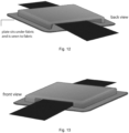
- any of the loops may comprise a plate, which is positioned under the fabric of the storage bin (i.e. such that the plate is not visible from the outside), and a top part, e.g. made in a soft material such as a polymer, wherein the top part is configured for receiving the strap.
- the plate and top part of the loops will together ensure that the loop(s) are fixed to the storage bin, since the two parts are positioned on opposite sides of the bag.
- the bag comprises two bottom loops placed on the bottom section of the bag.
- the bottom loops have a similar function as the other loops, i.e. the bottom loops comprises an opening for receiving the strap of the bag.
- the bottom loops comprises a first part, which is rigid, and a second part attached to the first part, wherein the second part defines an opening for receiving the strap.
- the first part may be provided as a plate, such as a plastic plate, which is sewn into the fabric of the bag, such that it is not visible from the outside of the bag.
- the second part is preferably provided as a top part attached to the plate.
- the top part may be rigid or flexible. Many materials are suitable for the top part, e.g. polymers or fabric.
- bottom loops are shown in figures 12-13 .
- Another embodiment of the bottom loops is shown in fig. 8 .
- the top part of the bottom loops may also comprise an angled side, such that the strap may exit the top part at an angle (see fig. 8-9 ).
- Each strap end attachment may be placed along an edge adjacent to a corner.
- One example of this is shown in Figure 3-5 .
- Each strap end attachment may be placed along an upper edge adjacent to a corner.
- FIG. 3-5 One example of this is shown in Figure 3-5 .
- At least one of the strap end attachments is a fixed bond, such as a glue bond, a thermal bond, or a stitch bond. More preferably, both ends of the strap end attachments are fixed by a fixed bond such as a glue bond, a thermal bond, or a stitch bond.
- the attachment may be included as a part of the joint of bin sides, for example by including the end attachments in the hem between the different parts of the bin, which may be sewed together.
- the strap ends could also be included in the glued edge if the edges are glued together, and hereby fastened to the bin.
- at least one of the ends of the strap is fixedly attached to the storage bin by stitching, thermal bonding, or by an adhesive.
- At least one of the strap end attachments may be configured such that the length of the strap encircling the storage bin can be adjusted. This will allow the user to adjust the length of the strap to have a perfect fit for the user. For instance, users with different height may need different lengths of the strap in order to carry the bag in a comfortable manner in both the shoulder bag configuration and in the rucksack configuration.
- at least one of the strap end attachments comprise an adjustable strap belt buckle. Other mechanisms of adjusting the length of the strap may be included. Also a combination of belt buckles and other mechanisms for adjusting the length of the strap may be included.
- the storage bin of the bag may comprise one or more slits of a size such that the strap can be passed through.
- At least one of the ends of the strap is passed through one of the slits, and said end is provided with an adjustable strap belt buckle.
- the buckle prevents the strap from being pulled through the slit.
- This arrangement may be an alternative to stitching the end of the strap to the bag, and has the advantage that the length of the strap can be adjusted via the belt buckle.
- Each slidable engagement may be placed along an edge adjacent to a corner. Placing the slidable engagements close to a corner may ensure that the strap can be encircling the bag in a manner in which it will not have to ever cross or even be present in the area of the bag touching the back of the user in rucksack mode. This will further increase the comfort for the user carrying the rucksack as no crossing strap is irritating the user while wearing the bag. If in addition the bag is 180 degrees symmetric the strap may be fixated and slidably engaged in a manner in which the strap is not crossing anywhere on either side of the bin which can be used to face the back of the user when in rucksack mode. This is illustrated by one example in Figures 3-5 . In the preferred embodiment two of the slidable engagements is placed along the upper edge adjacent to the corner.
- the slidable engagements are selected from the group of: metal loops, fabric loops, plastic loops and sleeves.
- the loops may also be fabricated from any other material.
- sleeves may be interpreted as an elongated patch of fabric or similar attached to the bag surface forming a sleeve-like structure and where the strap is entering the sleeve like structure at one point and passing under the patch and led back up from under the patch at another point.
- a sleeve slidable engagement is illustrated in fig. 6 .
- the bag further comprises at least seven or eight slidable engagements with the bin, wherein at least one of the slidable engagements is positioned away from the two opposite sides.
- These slidable engagements may be used to further guide the path of the strap or to support the strap in any other way for example by providing additional carrying points of the bag.
- the strap may comprise one or more pads for increasing the comfort when wearing the bag.
- the continuous strap is preferably pulled such that two shoulder straps are formed (see fig. 4 or fig. 7 ).
- each shoulder strap is provided with a pad.
- the pad(s) may comprise several layers as shown in fig. 10 .
- the pads preferably comprise one or more foam layers (e.g. EVA foam or soft PU foam), said foam layers ensuring a soft impact when worn.
- each shoulder strap is provided with a pad, wherein each pad comprises one or more layers of body fabric, one or more layers of foam, and a thin plastic board (e.g. made in polyethylene).
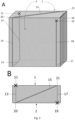
- Figure 3 shows a sketch of one embodiment of the present disclosure in which the path of the single continuous strap is illustrated.
- the big grey box illustrates the storage bin and the thin dashed lines illustrates the sides and the corner of the storage bin not visible from the given view.
- the thick lines indicate the path of the strap, and the thick line is dashed in the parts of the strap, which are not visible from the given point of view.
- Fig. 3A illustrates the bag seen from the side, viewed from slightly above the bag.
- the strap is fastened at the cross 11 on the side of the storage bin 1, not visible in the given perspective and led downwards along 12 on the side 1.
- the strap is then led below the storage bin 13 and up on the other side 2 which is visible in this illustration.
- the strap is then led along 14 all the way up to the top of side 2 at point 20. From here it is diagonally brought across the top-side along line 15 to reach the opposite corner on side 1 at point 21. From here it is led downwards along 16 and below the storage bin along 17 and back to side 2 where it is led along 18 to the cross 19 marking the position at which it is attached to the bin.
- the strap ends are attached to the bin at crosses 11 and 19, which may also be referred to as the strap end attachments, and the path of the strap encircling the storage bin may be divided into seven strap path sections 12-18.
- the strap is slidable engaged with the storage bin at strategic places to secure the path of the strap.
- the strap can hence move through loops or other slidable engagement mechanisms to allow access parts of the strap to be pulled to the area in which it is needed to make the bag into a rucksack or a shoulder bag.
- Fig. 3A shows one example of the bag comprising six slidable engagements placed at the intersection between the strap path segments, i.e. between segments 12-13, 13-14, 14-15, 15-16, 16-17, and between segments 17-18.
- the intersection between 14 and 15 has also been labelled 20 and the intersection between 15 and 16 has also been labelled 21 for the convenience of further descriptions.
- Fig. 3B shows a top-view of the bag in which the diagonal path 15 of the strap is clear.
- the two positions 11+19 in which the strap is attached to the storage bin is again marked and the dashed lines 13+17 indicates the path of the strap below the bag.
- the sections of the strap following the two sides of the storage bin 1 and 2 which are the strap sections 12, 14, 16 and 18 in Fig 1A are not visible from this illustrated top-view in Fig 1B .
- the strap encircling the storage bin comprises at least one section or part intended for carrying, e.g. a part configured for being in contact with the shoulder during shoulder bag use, or a part configured for being in contact with the shoulder(s) during rucksack use. This part may also be referred to as the access strap.
- Fig. 1 shows a sketch of one embodiment of the present disclosure in which the two different modes of the bag is illustrated, as a rucksack in Figure 1A or a shoulder bag in Figure 1B .
- the strap may be transformed from the first configuration to the second configuration, and vice versa, by a single, simple movement, as described below.
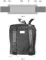
- Fig. 4 shows a sketch of the embodiment of Figure 3 in which the bag is in rucksack mode.
- the access strap is led to the two parts of the strap passing along side 2, so that the sections 14 and 18 of the strap is now longer so that the user can stick in the arms in each of the formed loops to wear the bag as a rucksack.
- the sections 12 and 16 of the strap may be made longer, so the user can stick the arms in each of the formed loops.
- each of the sides 1, 2 can face the back of a user during rucksack use.
- Fig. 2 shows a sketch of one embodiment of the present disclosure illustrating the transformation from shoulder bag to rucksack.
- the access strap length available as a shoulder strap in Fig. 2A can be pulled through the slidable engagements and pulled out at the straps on one of the two sides of the storage bin to form a rucksack as in Fig. 2B .
- the shoulder bag may be transformed into a rucksack by simply pulling the parts of the strap configured for being in contact with the shoulders during rucksack use.
- the bag is transformed.
- Figure 5 shows a sketch of the embodiment of Figure 3 and Figure 4 in which the bag is in shoulder bag mode.
- the shoulder bag mode can be reached from the rucksack mode of Figure 4 simply by pulling the strap section 15. This may happen by simply grapping the bag at the strap, in strap section 15, and lift the bag or let it drop towards the floor, in either case gravity will pull the bag downwards while the user pull the bag upwards. Regardless of the nature of the pull it will allow the access strap length previously available in the strap sections 14 and 18 to be released through the slidably engagement of the strap with the bin and result in excess length of the strap to transfer to the strap section 15. This results in the configuration such as the one shown in Figure 5 , which allows the bag to be worn as a shoulder bag.
- both opposite sides of the storage bin can face the back of a user during rucksack use.
- the opposite sides are 180 degrees rotation symmetric, as illustrated in Fig. 3A .
- the rotation axis is seen to be parallel and centrally placed between the opposite sides.
- the strap end attachments and slidable engagements are distributed such that the opposite sides are 180 degrees rotation symmetric.
- each strap end attachment and slidable engagement is advantageously placed adjacent to a corner.
- the strap end attachments may be placed at a diagonal distance to a corner, as illustrated in Fig. 3A , or along an edge adjacent to a corner, such as the upper edge adjacent to the corner, as illustrated in Fig. 2 .
- the strap end attachment may be formed by any fastening means.
- the ends are fastened by a fixed bond, such as fastened by glue or stitches.
- the fastening means may further comprise a length adjuster, such as a strap belt buckle, which can adjust the length of the access strap.
- the bag may be flexibly adjusted to be used by different persons having different height and dimensions.
- the slidable engagements adjacent to the diagonal strap section 15 on the upper side of storage bin, as shown in Fig. 5 are advantageously placed along the upper edge adjacent to the corner, for improved carriage comfort and stability.
- the stability of the slidable engagements, and the force needed for transformation of the bag depend on the materials and shapes.
- the slidable engagements are advantageously metal loops or fabric loops or sleeves.
- the bag advantageously comprises further slidable engagements, preferably where the additional slidable engagements are placed at other sides of the storage bin than the two opposite sides.
- the bag may comprise additional slidable engagements placed at the lower side of the storage bin.
- the slidable engagements are selected from the group of: metal loops, and fabric loops.
- the bag comprises at least seven or eight slidable engagements with the bin, wherein at least one of the slidable engagements is positioned away from the two opposite sides.
Landscapes
- Portable Outdoor Equipment (AREA)
- Purses, Travelling Bags, Baskets, Or Suitcases (AREA)
Claims (15)
- Tasche zur Verwendung als Rucksack und Umhängetasche, umfassend:- einen Aufbewahrungsbehälter mit zwei gegenüberliegenden Seiten (1, 2);- einen einzelnen umlaufenden Gurt, der den Aufbewahrungsbehälter umgibt, wobei die Enden des Gurtes an dem Aufbewahrungsbehälter an jeder der gegenüberliegenden Seiten (1, 2) an vordefinierten Befestigungspunkten (11, 19) befestigt sind; und- mindestens vier Schlaufen, die an dem Aufbewahrungsbehälter befestigt sind, wobei der Gurt durch jede der Schlaufen geführt ist, sodass der Gurt durch die Schlaufen gleiten kann;wobei die Befestigungspunkte (11, 19) und die vier Schlaufen derart verteilt sind, dass die Tasche mindestens zwei Konfigurationen aufweist:eine erste Konfiguration, wobei einer der Befestigungspunkte (11, 19) und drei der Schlaufen Tragepunkte für zwei Schultergurte definieren, sodass die Tasche zur Verwendung als Rucksack konfiguriert ist, undeine zweite Konfiguration, wobei sich der Gurt diagonal (15) zwischen zwei der an den gegenüberliegenden Seiten (1, 2) befindlichen Schlaufen über einen oberen Teil des Aufbewahrungsbehälters erstreckt, wobei die Tasche in dem sich diagonal (15) über den oberen Teil erstreckenden Gurt getragen werden kann, sodass die Tasche zur Verwendung als Umhängetasche konfiguriert ist.
- Tasche nach Anspruch 1, wobei jede der gegenüberliegenden Seiten (1, 2) mindestens eine der Schlaufen umfasst; und/oder wobei mindestens zwei der Schlaufen entlang einer oberen Kante des Aufbewahrungsbehälters angeordnet sind; und/oder wobei mindestens zwei der Schlaufen an einem Bodenabschnitt des Aufbewahrungsbehälters angeordnet sind; und/oder wobei sich die vordefinierten Befestigungspunkte (11, 19) an einem oberen Teil der beiden gegenüberliegenden Seiten (1, 2) befinden.
- Tasche nach einem der vorhergehenden Ansprüche, wobei der Aufbewahrungsbehälter einen oder mehrere Schlitze einer solchen Größe umfasst, dass der Gurt hindurchgeführt werden kann.
- Tasche nach Anspruch 3, wobei mindestens eines der Enden des Gurtes (11, 19) durch einen der Schlitze geführt ist und der Gurt eine verstellbare Gurtschnalle umfasst, die an dem Ende des Gurtes befestigt ist, wobei die Schnalle verhindert, dass der Gurt durch den Schlitz gezogen wird.
- Tasche nach einem der vorhergehenden Ansprüche, wobei mindestens eines der Enden des Gurtes (11, 19) durch Nähen, thermisches Bonden oder durch einen Klebstoff fest an dem Aufbewahrungsbehälter befestigt ist; und/oder
wobei beide Enden des Gurtes (11, 19) fest an dem Aufbewahrungsbehälter befestigt sind. - Tasche nach einem der vorhergehenden Ansprüche, wobei die Tasche mindestens sechs Schlaufen umfasst, die an dem Aufbewahrungsbehälter befestigt sind.
- Tasche nach einem der vorhergehenden Ansprüche, wobei die Tasche doppelt rotationssymmetrisch in Bezug auf eine zentrale vertikale Achse ist, die parallel zu den zwei gegenüberliegenden Seiten (1, 2) verläuft, sodass eine beliebige der gegenüberliegenden Seiten (1, 2) in der Rucksackkonfiguration dem Rücken eines Benutzers zugewandt sein kann.
- Tasche nach einem der vorhergehenden Ansprüche, wobei jede der gegenüberliegenden Seiten (1, 2) eine viereckige Form wie ein Quadrat oder Rechteck aufweist.
- Tasche nach Anspruch 8, wobei jeder Befestigungspunkt (11, 19) benachbart zu einer Ecke der gegenüberliegenden Seiten (1, 2) angeordnet ist; und/oderwobei jeder Befestigungspunkt (11, 19) in einem diagonalen Abstand zu einer Ecke angeordnet ist; und/oderwobei jeder Befestigungspunkt (11, 19) entlang einer Kante benachbart zu einer Ecke angeordnet ist; und/oder wobei jeder Befestigungspunkt (11, 19) entlang einer oberen Kante benachbart zu einer Ecke angeordnet ist.
- Tasche nach einem der vorhergehenden Ansprüche, wobei der Gurt derart ausgebildet ist, dass die Länge Gurtes eingestellt werden kann; oderwobei der Gurt derart ausgebildet ist, dass die Länge des Gurtes eingestellt werden kann undwobei der Gurt vorzugsweise eine verstellbare Gurtschnalle umfasst.
- Tasche nach einem der vorhergehenden Ansprüche, wobei jede der Schlaufen entlang einer Kante benachbart zu einer Ecke angeordnet ist.
- Tasche nach Anspruch 11, wobei zwei der Schlaufen entlang der oberen Kante benachbart zu der Ecke angeordnet sind.
- Tasche nach einem der vorhergehenden Ansprüche, wobei jede Schlaufe entlang einer Kante benachbart zu einer Ecke der Tasche angeordnet ist und wobei zwei der Schlaufen entlang der oberen Kante benachbart zu der Ecke angeordnet sind.
- Tasche nach einem der vorhergehenden Ansprüche, wobei der Gurt ein flacher Streifen in Form eines Gurtbandes ist.
- Tasche nach einem der vorhergehenden Ansprüche, wobei die Breite des Gurtes zwischen 3 und 5 cm, wie 4 cm, beträgt; und/oderwobei die Dicke des Gurtes weniger als 2 mm, wie 1 mm, beträgt, und/oderwobei die Schlaufen ein Metall, einen Kunststoff, ein Gewebe und/oder einen synthetischen Kautschuk, wie chlorsulfoniertes Polyethylen (CSPE), umfassen.
Applications Claiming Priority (2)
| Application Number | Priority Date | Filing Date | Title |
|---|---|---|---|
| DKPA202070327 | 2020-05-19 | ||
| PCT/EP2021/063331 WO2021234021A1 (en) | 2020-05-19 | 2021-05-19 | Combined rucksack and a shoulder bag |
Publications (3)
| Publication Number | Publication Date |
|---|---|
| EP4153003A1 EP4153003A1 (de) | 2023-03-29 |
| EP4153003C0 EP4153003C0 (de) | 2024-03-13 |
| EP4153003B1 true EP4153003B1 (de) | 2024-03-13 |
Family
ID=76181101
Family Applications (1)
| Application Number | Title | Priority Date | Filing Date |
|---|---|---|---|
| EP21728497.5A Active EP4153003B1 (de) | 2020-05-19 | 2021-05-19 | Rucksack und umhängetasche kombiniert |
Country Status (3)
| Country | Link |
|---|---|
| US (1) | US12089724B2 (de) |
| EP (1) | EP4153003B1 (de) |
| WO (1) | WO2021234021A1 (de) |
Families Citing this family (2)
| Publication number | Priority date | Publication date | Assignee | Title |
|---|---|---|---|---|
| US10623957B2 (en) * | 2015-04-21 | 2020-04-14 | Graham Dugoni | System and apparatus for selectively limiting user control of an electronic device |
| US20230320477A1 (en) * | 2021-08-04 | 2023-10-12 | Lucia Ida Del Priore | Combination playmat and backpack |
Family Cites Families (20)
| Publication number | Priority date | Publication date | Assignee | Title |
|---|---|---|---|---|
| US2210351A (en) * | 1937-06-01 | 1940-08-06 | William J Westendorf | Bag |
| US2902195A (en) * | 1958-04-09 | 1959-09-01 | Ralph R Marshall | Kit case |
| US3019952A (en) * | 1959-05-18 | 1962-02-06 | Brewster Forrest Oliver | Back pack convertible to hand-bag |
| FI161774A7 (de) | 1974-05-27 | 1975-11-28 | Kaarina Aolander | |
| US4273274A (en) | 1979-06-07 | 1981-06-16 | Freistadt Margo S | Convertible handbag and backpack |
| US5431317A (en) | 1994-02-24 | 1995-07-11 | Kliot; Eugene | Multimode traveling bag |
| US5415332A (en) * | 1994-02-24 | 1995-05-16 | Kliot; Eugene | Multimode traveling bag |
| US6220493B1 (en) * | 1997-05-05 | 2001-04-24 | Norihiro Iijima | Multi-way bag |
| US5927581A (en) * | 1997-07-22 | 1999-07-27 | Reddy; James P. | Convertible carrier |
| US6286461B1 (en) * | 1997-09-08 | 2001-09-11 | Gayle Martz, Inc. | Pet carrier with convertible straps |
| US7160028B1 (en) * | 1999-01-28 | 2007-01-09 | Linday Nancy L | Convertible tote bag |
| DE10055165C2 (de) | 2000-11-08 | 2002-11-14 | Bayerische Motoren Werke Ag | Umhängetasche |
| US8231037B2 (en) * | 2006-12-18 | 2012-07-31 | Jerome Elliot Sacks | Multi-mode strap apparatus for carrying bags |
| IL193743A0 (en) * | 2008-08-28 | 2009-08-03 | Wisey Products Ltd | Bag with adjustable strap adapted to be carried on shoulders or back |
| US8657169B2 (en) * | 2009-04-24 | 2014-02-25 | Joan F. Demskey | Backpack |
| US8746523B1 (en) * | 2011-02-16 | 2014-06-10 | Stephanie J. Woolley | Two way convertible shoulder strap construction |
| DE102011116293A1 (de) | 2011-10-18 | 2013-04-18 | Krista Tebbe | Tasche mit Trageriemen und Riemenverschluss |
| SI24647A (sl) | 2014-03-27 | 2015-09-30 | Lina Design D.O.O. | Torba |
| LT2014057A (lt) | 2014-04-04 | 2015-10-26 | Uab "Acme Europe" | Dvejopos paskirties krepšys, kuris naudojamas kaip ant peties nešiojamas krepšys arba kaip kuprinė, ir jo transformacijos būdas |
| WO2017210697A2 (en) * | 2016-06-03 | 2017-12-07 | Chung Coral | Convertible strap handbag |
-
2021
- 2021-05-19 WO PCT/EP2021/063331 patent/WO2021234021A1/en not_active Ceased
- 2021-05-19 EP EP21728497.5A patent/EP4153003B1/de active Active
- 2021-05-19 US US17/925,746 patent/US12089724B2/en active Active
Also Published As
| Publication number | Publication date |
|---|---|
| EP4153003A1 (de) | 2023-03-29 |
| US12089724B2 (en) | 2024-09-17 |
| US20230180919A1 (en) | 2023-06-15 |
| EP4153003C0 (de) | 2024-03-13 |
| WO2021234021A1 (en) | 2021-11-25 |
Similar Documents
| Publication | Publication Date | Title |
|---|---|---|
| AU755809B2 (en) | Ergonomic bookpack | |
| US5577652A (en) | Convertible backpack | |
| US5240159A (en) | Shoulder harness for backpack | |
| US7073942B2 (en) | Vertically expandable bag | |
| US5961014A (en) | Universal backpack harness | |
| KR100954496B1 (ko) | 슬라이딩 장치, 아기띠, 배낭, 가방 및 허리띠 배낭 | |
| EP4153003B1 (de) | Rucksack und umhängetasche kombiniert | |
| US20040031827A1 (en) | Backpack for carrying an umbrella and/or child hands free | |
| EP1178745A1 (de) | Rucksack mit abnehmbaren und verstellbaren tragriemen | |
| WO2010128979A2 (en) | Bag, tote, and backpack with channel-anchored drawstrings | |
| US10244851B1 (en) | Bag carrier | |
| US9888761B2 (en) | Backpack with suspension arrangement | |
| JP6584556B2 (ja) | 無段階式の背面長さ調節機能を備えたリュックサック | |
| EP0005369A2 (de) | In eine Schultertasche veränderbare Handtasche | |
| US20080023512A1 (en) | Cinching shoulder or back carried bag and method | |
| GB2511573A (en) | Backpack | |
| JPH08117026A (ja) | 背負い具用ひも及び背負い具 | |
| US5996871A (en) | Carrier belt for golf bag | |
| US12102217B1 (en) | Convertible tote | |
| US5735398A (en) | Golf bag with slidable strap | |
| US20180213920A1 (en) | Velcro document carrying mechanism providing adjustable, removable shoulder strap/padding with safety clasp and designs with value to be water repellent and to secure plans hands free | |
| KR200490314Y1 (ko) | 상체 착용식 다용도 스트랩 장치 | |
| WO2002082945A1 (en) | Sack | |
| CN214230244U (zh) | 一种收纳包 | |
| JPH064732Y2 (ja) | 背負い式バツグ |
Legal Events
| Date | Code | Title | Description |
|---|---|---|---|
| STAA | Information on the status of an ep patent application or granted ep patent |
Free format text: STATUS: UNKNOWN |
|
| STAA | Information on the status of an ep patent application or granted ep patent |
Free format text: STATUS: THE INTERNATIONAL PUBLICATION HAS BEEN MADE |
|
| PUAI | Public reference made under article 153(3) epc to a published international application that has entered the european phase |
Free format text: ORIGINAL CODE: 0009012 |
|
| STAA | Information on the status of an ep patent application or granted ep patent |
Free format text: STATUS: REQUEST FOR EXAMINATION WAS MADE |
|
| 17P | Request for examination filed |
Effective date: 20221205 |
|
| AK | Designated contracting states |
Kind code of ref document: A1 Designated state(s): AL AT BE BG CH CY CZ DE DK EE ES FI FR GB GR HR HU IE IS IT LI LT LU LV MC MK MT NL NO PL PT RO RS SE SI SK SM TR |
|
| DAV | Request for validation of the european patent (deleted) | ||
| DAX | Request for extension of the european patent (deleted) | ||
| GRAP | Despatch of communication of intention to grant a patent |
Free format text: ORIGINAL CODE: EPIDOSNIGR1 |
|
| STAA | Information on the status of an ep patent application or granted ep patent |
Free format text: STATUS: GRANT OF PATENT IS INTENDED |
|
| INTG | Intention to grant announced |
Effective date: 20231002 |
|
| GRAS | Grant fee paid |
Free format text: ORIGINAL CODE: EPIDOSNIGR3 |
|
| GRAA | (expected) grant |
Free format text: ORIGINAL CODE: 0009210 |
|
| STAA | Information on the status of an ep patent application or granted ep patent |
Free format text: STATUS: THE PATENT HAS BEEN GRANTED |
|
| AK | Designated contracting states |
Kind code of ref document: B1 Designated state(s): AL AT BE BG CH CY CZ DE DK EE ES FI FR GB GR HR HU IE IS IT LI LT LU LV MC MK MT NL NO PL PT RO RS SE SI SK SM TR |
|
| REG | Reference to a national code |
Ref country code: GB Ref legal event code: FG4D |
|
| REG | Reference to a national code |
Ref country code: CH Ref legal event code: EP |
|
| REG | Reference to a national code |
Ref country code: DE Ref legal event code: R096 Ref document number: 602021010451 Country of ref document: DE |
|
| REG | Reference to a national code |
Ref country code: IE Ref legal event code: FG4D |
|
| U01 | Request for unitary effect filed |
Effective date: 20240412 |
|
| U07 | Unitary effect registered |
Designated state(s): AT BE BG DE DK EE FI FR IT LT LU LV MT NL PT SE SI Effective date: 20240516 |
|
| U20 | Renewal fee for the european patent with unitary effect paid |
Year of fee payment: 4 Effective date: 20240529 |
|
| PG25 | Lapsed in a contracting state [announced via postgrant information from national office to epo] |
Ref country code: GR Free format text: LAPSE BECAUSE OF FAILURE TO SUBMIT A TRANSLATION OF THE DESCRIPTION OR TO PAY THE FEE WITHIN THE PRESCRIBED TIME-LIMIT Effective date: 20240614 |
|
| PG25 | Lapsed in a contracting state [announced via postgrant information from national office to epo] |
Ref country code: RS Free format text: LAPSE BECAUSE OF FAILURE TO SUBMIT A TRANSLATION OF THE DESCRIPTION OR TO PAY THE FEE WITHIN THE PRESCRIBED TIME-LIMIT Effective date: 20240613 Ref country code: HR Free format text: LAPSE BECAUSE OF FAILURE TO SUBMIT A TRANSLATION OF THE DESCRIPTION OR TO PAY THE FEE WITHIN THE PRESCRIBED TIME-LIMIT Effective date: 20240313 |
|
| PG25 | Lapsed in a contracting state [announced via postgrant information from national office to epo] |
Ref country code: ES Free format text: LAPSE BECAUSE OF FAILURE TO SUBMIT A TRANSLATION OF THE DESCRIPTION OR TO PAY THE FEE WITHIN THE PRESCRIBED TIME-LIMIT Effective date: 20240313 |
|
| PG25 | Lapsed in a contracting state [announced via postgrant information from national office to epo] |
Ref country code: RS Free format text: LAPSE BECAUSE OF FAILURE TO SUBMIT A TRANSLATION OF THE DESCRIPTION OR TO PAY THE FEE WITHIN THE PRESCRIBED TIME-LIMIT Effective date: 20240613 Ref country code: NO Free format text: LAPSE BECAUSE OF FAILURE TO SUBMIT A TRANSLATION OF THE DESCRIPTION OR TO PAY THE FEE WITHIN THE PRESCRIBED TIME-LIMIT Effective date: 20240613 Ref country code: HR Free format text: LAPSE BECAUSE OF FAILURE TO SUBMIT A TRANSLATION OF THE DESCRIPTION OR TO PAY THE FEE WITHIN THE PRESCRIBED TIME-LIMIT Effective date: 20240313 Ref country code: GR Free format text: LAPSE BECAUSE OF FAILURE TO SUBMIT A TRANSLATION OF THE DESCRIPTION OR TO PAY THE FEE WITHIN THE PRESCRIBED TIME-LIMIT Effective date: 20240614 Ref country code: ES Free format text: LAPSE BECAUSE OF FAILURE TO SUBMIT A TRANSLATION OF THE DESCRIPTION OR TO PAY THE FEE WITHIN THE PRESCRIBED TIME-LIMIT Effective date: 20240313 |
|
| PG25 | Lapsed in a contracting state [announced via postgrant information from national office to epo] |
Ref country code: IS Free format text: LAPSE BECAUSE OF FAILURE TO SUBMIT A TRANSLATION OF THE DESCRIPTION OR TO PAY THE FEE WITHIN THE PRESCRIBED TIME-LIMIT Effective date: 20240713 |
|
| PG25 | Lapsed in a contracting state [announced via postgrant information from national office to epo] |
Ref country code: SM Free format text: LAPSE BECAUSE OF FAILURE TO SUBMIT A TRANSLATION OF THE DESCRIPTION OR TO PAY THE FEE WITHIN THE PRESCRIBED TIME-LIMIT Effective date: 20240313 |
|
| PG25 | Lapsed in a contracting state [announced via postgrant information from national office to epo] |
Ref country code: CZ Free format text: LAPSE BECAUSE OF FAILURE TO SUBMIT A TRANSLATION OF THE DESCRIPTION OR TO PAY THE FEE WITHIN THE PRESCRIBED TIME-LIMIT Effective date: 20240313 |
|
| PG25 | Lapsed in a contracting state [announced via postgrant information from national office to epo] |
Ref country code: PL Free format text: LAPSE BECAUSE OF FAILURE TO SUBMIT A TRANSLATION OF THE DESCRIPTION OR TO PAY THE FEE WITHIN THE PRESCRIBED TIME-LIMIT Effective date: 20240313 |
|
| PG25 | Lapsed in a contracting state [announced via postgrant information from national office to epo] |
Ref country code: SK Free format text: LAPSE BECAUSE OF FAILURE TO SUBMIT A TRANSLATION OF THE DESCRIPTION OR TO PAY THE FEE WITHIN THE PRESCRIBED TIME-LIMIT Effective date: 20240313 |
|
| PG25 | Lapsed in a contracting state [announced via postgrant information from national office to epo] |
Ref country code: SM Free format text: LAPSE BECAUSE OF FAILURE TO SUBMIT A TRANSLATION OF THE DESCRIPTION OR TO PAY THE FEE WITHIN THE PRESCRIBED TIME-LIMIT Effective date: 20240313 Ref country code: SK Free format text: LAPSE BECAUSE OF FAILURE TO SUBMIT A TRANSLATION OF THE DESCRIPTION OR TO PAY THE FEE WITHIN THE PRESCRIBED TIME-LIMIT Effective date: 20240313 Ref country code: RO Free format text: LAPSE BECAUSE OF FAILURE TO SUBMIT A TRANSLATION OF THE DESCRIPTION OR TO PAY THE FEE WITHIN THE PRESCRIBED TIME-LIMIT Effective date: 20240313 Ref country code: PL Free format text: LAPSE BECAUSE OF FAILURE TO SUBMIT A TRANSLATION OF THE DESCRIPTION OR TO PAY THE FEE WITHIN THE PRESCRIBED TIME-LIMIT Effective date: 20240313 Ref country code: IS Free format text: LAPSE BECAUSE OF FAILURE TO SUBMIT A TRANSLATION OF THE DESCRIPTION OR TO PAY THE FEE WITHIN THE PRESCRIBED TIME-LIMIT Effective date: 20240713 Ref country code: CZ Free format text: LAPSE BECAUSE OF FAILURE TO SUBMIT A TRANSLATION OF THE DESCRIPTION OR TO PAY THE FEE WITHIN THE PRESCRIBED TIME-LIMIT Effective date: 20240313 |
|
| REG | Reference to a national code |
Ref country code: DE Ref legal event code: R097 Ref document number: 602021010451 Country of ref document: DE |
|
| REG | Reference to a national code |
Ref country code: CH Ref legal event code: PL |
|
| PG25 | Lapsed in a contracting state [announced via postgrant information from national office to epo] |
Ref country code: MC Free format text: LAPSE BECAUSE OF FAILURE TO SUBMIT A TRANSLATION OF THE DESCRIPTION OR TO PAY THE FEE WITHIN THE PRESCRIBED TIME-LIMIT Effective date: 20240313 |
|
| PLBE | No opposition filed within time limit |
Free format text: ORIGINAL CODE: 0009261 |
|
| STAA | Information on the status of an ep patent application or granted ep patent |
Free format text: STATUS: NO OPPOSITION FILED WITHIN TIME LIMIT |
|
| PG25 | Lapsed in a contracting state [announced via postgrant information from national office to epo] |
Ref country code: MC Free format text: LAPSE BECAUSE OF FAILURE TO SUBMIT A TRANSLATION OF THE DESCRIPTION OR TO PAY THE FEE WITHIN THE PRESCRIBED TIME-LIMIT Effective date: 20240313 Ref country code: CH Free format text: LAPSE BECAUSE OF NON-PAYMENT OF DUE FEES Effective date: 20240531 |
|
| 26N | No opposition filed |
Effective date: 20241216 |
|
| PG25 | Lapsed in a contracting state [announced via postgrant information from national office to epo] |
Ref country code: IE Free format text: LAPSE BECAUSE OF NON-PAYMENT OF DUE FEES Effective date: 20240519 |
|
| U20 | Renewal fee for the european patent with unitary effect paid |
Year of fee payment: 5 Effective date: 20250514 |
|
| PG25 | Lapsed in a contracting state [announced via postgrant information from national office to epo] |
Ref country code: CY Free format text: LAPSE BECAUSE OF FAILURE TO SUBMIT A TRANSLATION OF THE DESCRIPTION OR TO PAY THE FEE WITHIN THE PRESCRIBED TIME-LIMIT; INVALID AB INITIO Effective date: 20210519 |
|
| PG25 | Lapsed in a contracting state [announced via postgrant information from national office to epo] |
Ref country code: HU Free format text: LAPSE BECAUSE OF FAILURE TO SUBMIT A TRANSLATION OF THE DESCRIPTION OR TO PAY THE FEE WITHIN THE PRESCRIBED TIME-LIMIT; INVALID AB INITIO Effective date: 20210519 |
|
| GBPC | Gb: european patent ceased through non-payment of renewal fee |
Effective date: 20250519 |