EP4152504B1 - Sekundärbatterie - Google Patents
Sekundärbatterie Download PDFInfo
- Publication number
- EP4152504B1 EP4152504B1 EP20940670.1A EP20940670A EP4152504B1 EP 4152504 B1 EP4152504 B1 EP 4152504B1 EP 20940670 A EP20940670 A EP 20940670A EP 4152504 B1 EP4152504 B1 EP 4152504B1
- Authority
- EP
- European Patent Office
- Prior art keywords
- pouch
- secondary battery
- inner tube
- outer tube
- valve
- Prior art date
- Legal status (The legal status is an assumption and is not a legal conclusion. Google has not performed a legal analysis and makes no representation as to the accuracy of the status listed.)
- Active
Links
Images

Classifications
-
- H—ELECTRICITY
- H01—ELECTRIC ELEMENTS
- H01M—PROCESSES OR MEANS, e.g. BATTERIES, FOR THE DIRECT CONVERSION OF CHEMICAL ENERGY INTO ELECTRICAL ENERGY
- H01M50/00—Constructional details or processes of manufacture of the non-active parts of electrochemical cells other than fuel cells, e.g. hybrid cells
- H01M50/30—Arrangements for facilitating escape of gases
- H01M50/35—Gas exhaust passages comprising elongated, tortuous or labyrinth-shaped exhaust passages
-
- H—ELECTRICITY
- H01—ELECTRIC ELEMENTS
- H01M—PROCESSES OR MEANS, e.g. BATTERIES, FOR THE DIRECT CONVERSION OF CHEMICAL ENERGY INTO ELECTRICAL ENERGY
- H01M50/00—Constructional details or processes of manufacture of the non-active parts of electrochemical cells other than fuel cells, e.g. hybrid cells
- H01M50/10—Primary casings; Jackets or wrappings
- H01M50/102—Primary casings; Jackets or wrappings characterised by their shape or physical structure
- H01M50/105—Pouches or flexible bags
-
- H—ELECTRICITY
- H01—ELECTRIC ELEMENTS
- H01M—PROCESSES OR MEANS, e.g. BATTERIES, FOR THE DIRECT CONVERSION OF CHEMICAL ENERGY INTO ELECTRICAL ENERGY
- H01M50/00—Constructional details or processes of manufacture of the non-active parts of electrochemical cells other than fuel cells, e.g. hybrid cells
- H01M50/10—Primary casings; Jackets or wrappings
- H01M50/116—Primary casings; Jackets or wrappings characterised by the material
-
- H—ELECTRICITY
- H01—ELECTRIC ELEMENTS
- H01M—PROCESSES OR MEANS, e.g. BATTERIES, FOR THE DIRECT CONVERSION OF CHEMICAL ENERGY INTO ELECTRICAL ENERGY
- H01M50/00—Constructional details or processes of manufacture of the non-active parts of electrochemical cells other than fuel cells, e.g. hybrid cells
- H01M50/20—Mountings; Secondary casings or frames; Racks, modules or packs; Suspension devices; Shock absorbers; Transport or carrying devices; Holders
- H01M50/204—Racks, modules or packs for multiple batteries or multiple cells
- H01M50/207—Racks, modules or packs for multiple batteries or multiple cells characterised by their shape
- H01M50/211—Racks, modules or packs for multiple batteries or multiple cells characterised by their shape adapted for pouch cells
-
- H—ELECTRICITY
- H01—ELECTRIC ELEMENTS
- H01M—PROCESSES OR MEANS, e.g. BATTERIES, FOR THE DIRECT CONVERSION OF CHEMICAL ENERGY INTO ELECTRICAL ENERGY
- H01M50/00—Constructional details or processes of manufacture of the non-active parts of electrochemical cells other than fuel cells, e.g. hybrid cells
- H01M50/30—Arrangements for facilitating escape of gases
- H01M50/317—Re-sealable arrangements
- H01M50/325—Re-sealable arrangements comprising deformable valve members, e.g. elastic or flexible valve members
-
- H—ELECTRICITY
- H01—ELECTRIC ELEMENTS
- H01M—PROCESSES OR MEANS, e.g. BATTERIES, FOR THE DIRECT CONVERSION OF CHEMICAL ENERGY INTO ELECTRICAL ENERGY
- H01M50/00—Constructional details or processes of manufacture of the non-active parts of electrochemical cells other than fuel cells, e.g. hybrid cells
- H01M50/30—Arrangements for facilitating escape of gases
- H01M50/342—Non-re-sealable arrangements
-
- H—ELECTRICITY
- H01—ELECTRIC ELEMENTS
- H01M—PROCESSES OR MEANS, e.g. BATTERIES, FOR THE DIRECT CONVERSION OF CHEMICAL ENERGY INTO ELECTRICAL ENERGY
- H01M2200/00—Safety devices for primary or secondary batteries
- H01M2200/20—Pressure-sensitive devices
-
- Y—GENERAL TAGGING OF NEW TECHNOLOGICAL DEVELOPMENTS; GENERAL TAGGING OF CROSS-SECTIONAL TECHNOLOGIES SPANNING OVER SEVERAL SECTIONS OF THE IPC; TECHNICAL SUBJECTS COVERED BY FORMER USPC CROSS-REFERENCE ART COLLECTIONS [XRACs] AND DIGESTS
- Y02—TECHNOLOGIES OR APPLICATIONS FOR MITIGATION OR ADAPTATION AGAINST CLIMATE CHANGE
- Y02E—REDUCTION OF GREENHOUSE GAS [GHG] EMISSIONS, RELATED TO ENERGY GENERATION, TRANSMISSION OR DISTRIBUTION
- Y02E60/00—Enabling technologies; Technologies with a potential or indirect contribution to GHG emissions mitigation
- Y02E60/10—Energy storage using batteries
-
- Y—GENERAL TAGGING OF NEW TECHNOLOGICAL DEVELOPMENTS; GENERAL TAGGING OF CROSS-SECTIONAL TECHNOLOGIES SPANNING OVER SEVERAL SECTIONS OF THE IPC; TECHNICAL SUBJECTS COVERED BY FORMER USPC CROSS-REFERENCE ART COLLECTIONS [XRACs] AND DIGESTS
- Y02—TECHNOLOGIES OR APPLICATIONS FOR MITIGATION OR ADAPTATION AGAINST CLIMATE CHANGE
- Y02P—CLIMATE CHANGE MITIGATION TECHNOLOGIES IN THE PRODUCTION OR PROCESSING OF GOODS
- Y02P70/00—Climate change mitigation technologies in the production process for final industrial or consumer products
- Y02P70/50—Manufacturing or production processes characterised by the final manufactured product
Definitions
- the present invention relates to a secondary battery in which an electrode assembly and an electrolyte are embedded in a pouch, and more particularly, to a pouch-type secondary battery having a valve capable of discharging a gas to the outside when the gas is generated in the pouch.
- the demands for high-efficiency secondary batteries are rapidly increasing in the mobile device and electric vehicle fields.
- a lithium secondary battery having high energy density, maintaining a relatively high voltage, and having a low self-discharge rate is commercially widely used, and research and development for improving performance thereof is actively being conducted.
- the secondary battery has a structure in which an electrode assembly and an electrolyte are embedded in a case such as a can or a pouch.
- the electrode assembly has a structure in which positive electrodes, separators, and negative electrodes are repeatedly stacked.
- the electrode assembly may be classified into a winding type electrode assembly in which the positive electrodes, the separators, and the negative electrodes, which are in the stacked state, are rolled to be embedded in the case and a stack type (stacked) electrode assembly in which the positive electrodes, the separators, and the negative electrodes, each of which is cut to a predetermined size, are stacked.
- the winding type electrode assembly Since the winding type electrode assembly has a spirally wound structure, the winding type electrode assembly is suitable for being mounted on a cylindrical battery, but is disadvantageous in space utilization for a prismatic or pouch type battery. On the other hand, since the stack type electrode assembly is adjusted in size when the electrode and the separator are cut, the prismatic shape fitted with the case is easily obtained, but a manufacturing process is relatively complicated, and the stack type electrode assembly is relatively vulnerable to an external impact. Also, a stack & folding method has been developed to combine the advantages of the winding type and the stack type.
- a C-type bicell (a bicell having a stack structure of a positive electrode/separator/negative electrode/separator/positive electrode) and an A-type bicell (a bicell having a stack structure of a negative electrode/separator/positive electrode/separator/negative electrode) are placed on a folding separator to fold the bicells, thereby manufacturing the electrode assembly.
- the electrode assembly manufactured in various manners as described above is mounted in a case such as a can or a pouch.
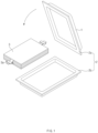
- the pouch-type battery has a problem in that swelling occurs during the charging/discharging in the manufacturing process and during the use as a charging/discharging device after the manufacturing is performed.
- Such swelling is a phenomenon in which a gas is generated inside the pouch 1 due to the vaporization of the electrolyte to deform an outer appearance of the pouch 1 and deteriorate charge/discharge performance of the secondary battery, and in severe cases, there is a risk of explosion.
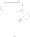
- an object of the present invention is to provide a secondary battery having a valve capable of discharging a gas to the outside when the gas is generated inside a pouch to increase in internal pressure.
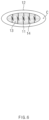
- both ends of the outer tube 12 and the inner tube 11 are connected to each other to be sealed so that a chamber C that is a sealed space is formed between the outer tube 12 and the inner tube 11.
- the inner tube 11 may be deformed within the outer tube 12 in a direction in which a diameter thereof is expanded.
- the outer tube 12 is manufactured with relatively low flexibility and high rigidity compared to the inner tube 11, and the inner tube 11 is manufactured with relatively high flexibility and low rigidity compared to the outer tube 12.
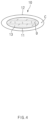
- the flexibility and rigidity may be adjusted by controlling molding conditions or adding additives.
- a pressure at which a gap g is generated and an expansion speed of the gap may be reduced.
Landscapes
- Chemical & Material Sciences (AREA)
- Chemical Kinetics & Catalysis (AREA)
- Electrochemistry (AREA)
- General Chemical & Material Sciences (AREA)
- Gas Exhaust Devices For Batteries (AREA)
- Sealing Battery Cases Or Jackets (AREA)
Claims (11)
- Sekundärbatterie, welche mit einem Beutel (1) bereitgestellt ist, in welchem ein Dichtungsabschnitt (2a, 2b), welcher an einem Rand (2) davon ausgebildet ist, abgedichtet ist, wenn eine Elektrodenanordnung (3) und ein Elektrolyt eingeschlossen sind, wobei die Sekundärbatterie umfasst:ein Ventil (10), welches an einem Dichtungsabschnitt (2a, 2b) angebracht ist, so dass ein Ende davon innerhalb des Beutels (1) angeordnet ist und das andere Ende davon außerhalb des Beutels angeordnet ist, und welche ein Gas, welches innerhalb des Beutels generiert ist, zu der Außenseite abführt,dadurch gekennzeichnet, dass das Ventil (10) ein inneres Rohr (11) umfasst, welches mit einem Haftmittel (13) befüllt ist und aus einem Material hergestellt ist, welches deformiert wird, wenn eine Schwellung auftritt, undwenn die Schwellung auftritt, aufgrund eines erhöhten Drucks innerhalb des Beutels (1), ein Spalt in einem Abschnitt generiert wird, welcher mit dem Haftmittel (13) gefüllt ist, und das Gas in dem Beutel (1) zu der Außenseite durch den Spalt abgeführt wird.
- Sekundärbatterie nach Anspruch 1, wobei das Ventil (10) ein äußeres Rohr (12) umfasst, welches an dem Dichtungsabschnitt (2a, 2b) angebracht ist, so dass ein Ende davon innerhalb des Beutels (1) angeordnet ist und das andere Ende davon außerhalb des Beutels (1) angeordnet ist und angebracht ist, so dass das innere Rohr (11) in einer Längsrichtung innerhalb des äußeren Rohrs (12) eingeführt ist,wobei beide Enden des äußeren Rohrs (12) und des inneren Rohrs (11) miteinander verbunden sind, um abgedichtet zu sein, so dass eine Kammer (C), welche ein abgedichteter Raum ist, zwischen dem äußeren Rohr (12) und dem inneren Rohr (1) ausgebildet ist, undwobei das innere Rohr (11) innerhalb des äußeren Rohrs (12) deformiert ist.
- Sekundärbatterie nach Anspruch 2, wobei das äußere Rohr (12) aus einem Material hergestellt ist, welches nicht deformiert wird, selbst wenn die Schwellung aufritt, und
wobei, wenn die Schwellung auftritt, um einen Druck innerhalb des Beutels zu erhöhen, das innere Rohr (11) deformiert wird, so dass ein Volumen der Kammer (C) schrumpft. - Sekundärbatterie nach Anspruch 3, wobei jedes aus dem äußeren Rohr (12) und dem inneren Rohr (11) aus Polypropylen hergestellt ist, welches ein Material ist, welches in dem Beutel enthalten ist,
wobei das äußere Rohr (12) eine relativ geringe Flexibilität und eine hohe Steifigkeit im Vergleich zu dem inneren Rohr (11) aufweist und das innere Rohr (11) eine relativ hohe Flexibilität und eine geringe Steifigkeit im Vergleich zu dem äußeren Rohr (12) aufweist. - Sekundärbatterie nach Anspruch 2, ferner umfassend gasförmigen Stickstoff (N2) in der Kammer (C).
- Sekundärbatterie nach Anspruch 2, wobei jedes aus dem äußeren Rohr (12) und dem inneren Rohr (11) einen kreisförmigen oder einen elliptischen Querschnitt aufweist.
- Sekundärbatterie nach Anspruch 1, wobei das Haftmittel (13) ein Epoxid-Bindemittel enthält.
- Sekundärbatterie nach Anspruch 1, wobei das Haftmittel (13) ein Acrylat-Bindemittel enthält.
- Sekundärbatterie nach Anspruch 1, wobei eine Mehrzahl von Haken (14) in dem inneren Rohr (11) an jeder der einen Fläche und der anderen Fläche installiert sind, welche einander zuweisen, so dass die Haken (14) physisch miteinander in einer Klettverschluss-Weise gekoppelt sind.
- Sekundärbatterie nach Anspruch 1, wobei das Ventil (10) parallel zu einer Elektrodenleitung (3a) angeordnet ist, welche aus der Elektrodenanordnung (3) herausgezogen ist, um aus dem Beutel vorzustehen.
- Sekundärbatteriemodul, umfassend eine Mehrzahl von Sekundärbatterien nach einem der Ansprüche 1 bis 10, welche miteinander gekoppelt sind.
Applications Claiming Priority (2)
| Application Number | Priority Date | Filing Date | Title |
|---|---|---|---|
| KR1020200072596A KR102756131B1 (ko) | 2020-06-15 | 2020-06-15 | 이차전지 |
| PCT/KR2020/016181 WO2021256629A1 (ko) | 2020-06-15 | 2020-11-17 | 이차전지 |
Publications (3)
| Publication Number | Publication Date |
|---|---|
| EP4152504A1 EP4152504A1 (de) | 2023-03-22 |
| EP4152504A4 EP4152504A4 (de) | 2024-07-24 |
| EP4152504B1 true EP4152504B1 (de) | 2025-07-09 |
Family
ID=79164339
Family Applications (1)
| Application Number | Title | Priority Date | Filing Date |
|---|---|---|---|
| EP20940670.1A Active EP4152504B1 (de) | 2020-06-15 | 2020-11-17 | Sekundärbatterie |
Country Status (9)
| Country | Link |
|---|---|
| US (1) | US20230223645A1 (de) |
| EP (1) | EP4152504B1 (de) |
| JP (1) | JP7551211B2 (de) |
| KR (1) | KR102756131B1 (de) |
| CN (1) | CN115699432A (de) |
| ES (1) | ES3036659T3 (de) |
| HU (1) | HUE072812T2 (de) |
| PL (1) | PL4152504T3 (de) |
| WO (1) | WO2021256629A1 (de) |
Families Citing this family (1)
| Publication number | Priority date | Publication date | Assignee | Title |
|---|---|---|---|---|
| KR102904071B1 (ko) * | 2022-08-03 | 2025-12-24 | 주식회사 엘지에너지솔루션 | 가스 포집용 튜브 장치 |
Family Cites Families (26)
| Publication number | Priority date | Publication date | Assignee | Title |
|---|---|---|---|---|
| US4678725A (en) * | 1983-05-11 | 1987-07-07 | Matsushita Electric Industrial Co., Inc. | Hermetically sealed storage battery |
| JPH0670156U (ja) * | 1993-03-15 | 1994-09-30 | 日本電池株式会社 | 有機電解液二次電池 |
| US20030232236A1 (en) | 2002-06-14 | 2003-12-18 | Mitchell Porter H. | Battery package vent |
| JP4249698B2 (ja) * | 2004-11-25 | 2009-04-02 | 日本電気株式会社 | フィルム外装電気デバイスおよびフィルム外装電気デバイス集合体 |
| CN102280604B (zh) | 2005-03-17 | 2014-11-12 | 日本电气株式会社 | 覆膜电气设备及其制造方法 |
| JP5204973B2 (ja) * | 2006-12-21 | 2013-06-05 | 株式会社ゼロム | 二次電池用安全弁構造及びその製造方法 |
| JP4900339B2 (ja) * | 2008-08-01 | 2012-03-21 | 日本電気株式会社 | フィルム外装電気デバイスおよびその製造方法 |
| JP5487743B2 (ja) | 2009-06-12 | 2014-05-07 | 日産自動車株式会社 | 薄型電池及びその製造方法 |
| US20110284536A1 (en) * | 2010-05-22 | 2011-11-24 | William Walters | One Way Degassing Valve |
| KR101273472B1 (ko) * | 2010-11-10 | 2013-06-14 | 주식회사 이아이지 | 파우치형 이차 전지의 제조 방법 및 이에 의한 파우치형 이차 전지 |
| WO2013146803A1 (ja) * | 2012-03-28 | 2013-10-03 | 株式会社オプトニクス精密 | 安全弁および電気化学素子 |
| KR20140067246A (ko) * | 2012-11-26 | 2014-06-05 | 주식회사 엘지화학 | 노즐 부재가 장착되어 있는 전지셀 |
| JP2015041767A (ja) * | 2013-08-20 | 2015-03-02 | 睦月電機株式会社 | 密閉型電気化学デバイス用封口体 |
| KR20150039290A (ko) * | 2013-10-02 | 2015-04-10 | 주식회사 엘지화학 | 경화성 물질로 코팅되어 있는 밀봉부를 포함하는 휘어진 형상의 파우치형 리튬 이차전지 |
| KR20150089464A (ko) | 2014-01-28 | 2015-08-05 | 주식회사 엘지화학 | 전지모듈 |
| US20170210532A1 (en) * | 2014-07-07 | 2017-07-27 | Eliezer Edelstein | Pouch with flat valve |
| KR102159368B1 (ko) * | 2016-03-03 | 2020-09-23 | 주식회사 엘지화학 | 전기화학소자용 파우치 외장재 |
| CN109417134B (zh) * | 2016-06-29 | 2021-12-03 | 三洋电机株式会社 | 二次电池 |
| CN106479060A (zh) * | 2016-12-13 | 2017-03-08 | 罗锐明 | 一种汽车真空泵 |
| KR102555751B1 (ko) | 2017-10-17 | 2023-07-14 | 주식회사 엘지에너지솔루션 | 가스 배출이 가능한 이차전지용 파우치형 케이스 |
| KR102361569B1 (ko) * | 2018-04-23 | 2022-02-10 | 주식회사 엘지에너지솔루션 | 가스배출수단이 구비된 파우치형 이차전지 |
| JP7040294B2 (ja) | 2018-05-28 | 2022-03-23 | 大日本印刷株式会社 | 電池 |
| KR102693457B1 (ko) * | 2018-09-20 | 2024-08-07 | 주식회사 엘지에너지솔루션 | 가스배출 탭을 구비한 파우치형 이차전지 및 파우치형 이차전지 디가스 장치 |
| JP2020063058A (ja) | 2018-10-15 | 2020-04-23 | 大日本印刷株式会社 | 弁及びこれを備える包装体 |
| CN210272567U (zh) * | 2019-06-10 | 2020-04-07 | 欣旺达电动汽车电池有限公司 | 一种动力电池软包电芯 |
| KR102726467B1 (ko) * | 2019-09-30 | 2024-11-06 | 주식회사 엘지에너지솔루션 | 가스포켓을 포함하는 파우치형 이차전지 |
-
2020
- 2020-06-15 KR KR1020200072596A patent/KR102756131B1/ko active Active
- 2020-11-17 PL PL20940670.1T patent/PL4152504T3/pl unknown
- 2020-11-17 ES ES20940670T patent/ES3036659T3/es active Active
- 2020-11-17 WO PCT/KR2020/016181 patent/WO2021256629A1/ko not_active Ceased
- 2020-11-17 US US18/009,532 patent/US20230223645A1/en active Pending
- 2020-11-17 CN CN202080101760.5A patent/CN115699432A/zh active Pending
- 2020-11-17 JP JP2022575823A patent/JP7551211B2/ja active Active
- 2020-11-17 HU HUE20940670A patent/HUE072812T2/hu unknown
- 2020-11-17 EP EP20940670.1A patent/EP4152504B1/de active Active
Also Published As
| Publication number | Publication date |
|---|---|
| KR20210155279A (ko) | 2021-12-22 |
| CN115699432A (zh) | 2023-02-03 |
| EP4152504A4 (de) | 2024-07-24 |
| HUE072812T2 (hu) | 2025-12-28 |
| WO2021256629A1 (ko) | 2021-12-23 |
| KR102756131B1 (ko) | 2025-01-17 |
| PL4152504T3 (pl) | 2025-09-08 |
| JP7551211B2 (ja) | 2024-09-17 |
| US20230223645A1 (en) | 2023-07-13 |
| JP2023529685A (ja) | 2023-07-11 |
| EP4152504A1 (de) | 2023-03-22 |
| ES3036659T3 (en) | 2025-09-23 |
Similar Documents
| Publication | Publication Date | Title |
|---|---|---|
| CN112467231B (zh) | 电极组件、电池单体、电池及电极组件的制造方法和设备 | |
| US20240154238A1 (en) | Battery pack and vehicle comprising the same | |
| KR101915325B1 (ko) | 이차전지 | |
| KR102308423B1 (ko) | 형상 기억 합금체가 형성되어 있는 탑 캡을 구비하는 전지셀 | |
| KR100313119B1 (ko) | 이차전지의 전극군 | |
| US20230318132A1 (en) | Battery module with reinforced safety | |
| KR101897223B1 (ko) | 파우치형 이차전지 | |
| EP4187692B1 (de) | Batteriezelle und batteriemodul damit | |
| EP3654412B1 (de) | Sekundärbatterie | |
| EP4152504B1 (de) | Sekundärbatterie | |
| US20230361399A1 (en) | Secondary battery | |
| KR101243560B1 (ko) | 파우치형 리튬 이차 전지 | |
| EP4156396B1 (de) | Sekundärbatterie | |
| EP4195377A1 (de) | Batteriezelle und batteriemodul damit | |
| EP4138189A1 (de) | Sekundärbatteriemodul und verfahren zur herstellung davon | |
| CN112751109B (zh) | 袋型二次电池 | |
| EP4601085A1 (de) | Beutelartige sekundärbatterie | |
| EP4379918A1 (de) | Batteriezelle und batteriemodul damit | |
| EP4250467A1 (de) | Sekundärbatterie und herstellungsverfahren dafür | |
| KR20140013132A (ko) | 이차전지 | |
| US12519177B2 (en) | Battery cell, and battery module, battery pack and vehicle including the same | |
| US20250266578A1 (en) | Electrode assembly retainer, secondary battery including the same, and method of fabricating secondary battery including the same | |
| US20250132445A1 (en) | Battery module | |
| EP4708529A1 (de) | Batteriemodul und batteriepack damit | |
| EP4106090B1 (de) | Batteriezelle und batteriemodul damit |
Legal Events
| Date | Code | Title | Description |
|---|---|---|---|
| STAA | Information on the status of an ep patent application or granted ep patent |
Free format text: STATUS: THE INTERNATIONAL PUBLICATION HAS BEEN MADE |
|
| PUAI | Public reference made under article 153(3) epc to a published international application that has entered the european phase |
Free format text: ORIGINAL CODE: 0009012 |
|
| STAA | Information on the status of an ep patent application or granted ep patent |
Free format text: STATUS: REQUEST FOR EXAMINATION WAS MADE |
|
| 17P | Request for examination filed |
Effective date: 20221212 |
|
| AK | Designated contracting states |
Kind code of ref document: A1 Designated state(s): AL AT BE BG CH CY CZ DE DK EE ES FI FR GB GR HR HU IE IS IT LI LT LU LV MC MK MT NL NO PL PT RO RS SE SI SK SM TR |
|
| DAV | Request for validation of the european patent (deleted) | ||
| DAX | Request for extension of the european patent (deleted) | ||
| A4 | Supplementary search report drawn up and despatched |
Effective date: 20240626 |
|
| RIC1 | Information provided on ipc code assigned before grant |
Ipc: H01M 50/325 20210101ALI20240620BHEP Ipc: H01M 50/105 20210101ALI20240620BHEP Ipc: H01M 50/10 20210101ALI20240620BHEP Ipc: H01M 50/30 20210101AFI20240620BHEP |
|
| GRAP | Despatch of communication of intention to grant a patent |
Free format text: ORIGINAL CODE: EPIDOSNIGR1 |
|
| STAA | Information on the status of an ep patent application or granted ep patent |
Free format text: STATUS: GRANT OF PATENT IS INTENDED |
|
| GRAS | Grant fee paid |
Free format text: ORIGINAL CODE: EPIDOSNIGR3 |
|
| INTG | Intention to grant announced |
Effective date: 20250507 |
|
| GRAA | (expected) grant |
Free format text: ORIGINAL CODE: 0009210 |
|
| STAA | Information on the status of an ep patent application or granted ep patent |
Free format text: STATUS: THE PATENT HAS BEEN GRANTED |
|
| AK | Designated contracting states |
Kind code of ref document: B1 Designated state(s): AL AT BE BG CH CY CZ DE DK EE ES FI FR GB GR HR HU IE IS IT LI LT LU LV MC MK MT NL NO PL PT RO RS SE SI SK SM TR |
|
| P01 | Opt-out of the competence of the unified patent court (upc) registered |
Free format text: CASE NUMBER: APP_26053/2025 Effective date: 20250602 |
|
| REG | Reference to a national code |
Ref country code: GB Ref legal event code: FG4D |
|
| REG | Reference to a national code |
Ref country code: CH Ref legal event code: EP |
|
| REG | Reference to a national code |
Ref country code: IE Ref legal event code: FG4D |
|
| REG | Reference to a national code |
Ref country code: DE Ref legal event code: R096 Ref document number: 602020054421 Country of ref document: DE |
|
| REG | Reference to a national code |
Ref country code: SE Ref legal event code: TRGR |
|
| REG | Reference to a national code |
Ref country code: ES Ref legal event code: FG2A Ref document number: 3036659 Country of ref document: ES Kind code of ref document: T3 Effective date: 20250923 |
|
| REG | Reference to a national code |
Ref country code: NL Ref legal event code: MP Effective date: 20250709 |
|
| PG25 | Lapsed in a contracting state [announced via postgrant information from national office to epo] |
Ref country code: PT Free format text: LAPSE BECAUSE OF FAILURE TO SUBMIT A TRANSLATION OF THE DESCRIPTION OR TO PAY THE FEE WITHIN THE PRESCRIBED TIME-LIMIT Effective date: 20251110 |
|
| PGFP | Annual fee paid to national office [announced via postgrant information from national office to epo] |
Ref country code: HU Payment date: 20251127 Year of fee payment: 6 |
|
| PG25 | Lapsed in a contracting state [announced via postgrant information from national office to epo] |
Ref country code: NL Free format text: LAPSE BECAUSE OF FAILURE TO SUBMIT A TRANSLATION OF THE DESCRIPTION OR TO PAY THE FEE WITHIN THE PRESCRIBED TIME-LIMIT Effective date: 20250709 |
|
| REG | Reference to a national code |
Ref country code: AT Ref legal event code: MK05 Ref document number: 1812766 Country of ref document: AT Kind code of ref document: T Effective date: 20250709 |
|
| REG | Reference to a national code |
Ref country code: HU Ref legal event code: AG4A Ref document number: E072812 Country of ref document: HU |
|
| PG25 | Lapsed in a contracting state [announced via postgrant information from national office to epo] |
Ref country code: IS Free format text: LAPSE BECAUSE OF FAILURE TO SUBMIT A TRANSLATION OF THE DESCRIPTION OR TO PAY THE FEE WITHIN THE PRESCRIBED TIME-LIMIT Effective date: 20251109 |
|
| PGFP | Annual fee paid to national office [announced via postgrant information from national office to epo] |
Ref country code: DE Payment date: 20251020 Year of fee payment: 6 |
|
| PGFP | Annual fee paid to national office [announced via postgrant information from national office to epo] |
Ref country code: GB Payment date: 20251023 Year of fee payment: 6 |
|
| PG25 | Lapsed in a contracting state [announced via postgrant information from national office to epo] |
Ref country code: NO Free format text: LAPSE BECAUSE OF FAILURE TO SUBMIT A TRANSLATION OF THE DESCRIPTION OR TO PAY THE FEE WITHIN THE PRESCRIBED TIME-LIMIT Effective date: 20251009 |
|
| REG | Reference to a national code |
Ref country code: LT Ref legal event code: MG9D |
|
| PG25 | Lapsed in a contracting state [announced via postgrant information from national office to epo] |
Ref country code: AT Free format text: LAPSE BECAUSE OF FAILURE TO SUBMIT A TRANSLATION OF THE DESCRIPTION OR TO PAY THE FEE WITHIN THE PRESCRIBED TIME-LIMIT Effective date: 20250709 |
|
| PG25 | Lapsed in a contracting state [announced via postgrant information from national office to epo] |
Ref country code: FI Free format text: LAPSE BECAUSE OF FAILURE TO SUBMIT A TRANSLATION OF THE DESCRIPTION OR TO PAY THE FEE WITHIN THE PRESCRIBED TIME-LIMIT Effective date: 20250709 |
|
| PG25 | Lapsed in a contracting state [announced via postgrant information from national office to epo] |
Ref country code: HR Free format text: LAPSE BECAUSE OF FAILURE TO SUBMIT A TRANSLATION OF THE DESCRIPTION OR TO PAY THE FEE WITHIN THE PRESCRIBED TIME-LIMIT Effective date: 20250709 |
|
| PGFP | Annual fee paid to national office [announced via postgrant information from national office to epo] |
Ref country code: FR Payment date: 20251021 Year of fee payment: 6 |
|
| PG25 | Lapsed in a contracting state [announced via postgrant information from national office to epo] |
Ref country code: GR Free format text: LAPSE BECAUSE OF FAILURE TO SUBMIT A TRANSLATION OF THE DESCRIPTION OR TO PAY THE FEE WITHIN THE PRESCRIBED TIME-LIMIT Effective date: 20251010 |
|
| PGFP | Annual fee paid to national office [announced via postgrant information from national office to epo] |
Ref country code: BE Payment date: 20251020 Year of fee payment: 6 |
|
| PGFP | Annual fee paid to national office [announced via postgrant information from national office to epo] |
Ref country code: SE Payment date: 20251021 Year of fee payment: 6 |
|
| PG25 | Lapsed in a contracting state [announced via postgrant information from national office to epo] |
Ref country code: LV Free format text: LAPSE BECAUSE OF FAILURE TO SUBMIT A TRANSLATION OF THE DESCRIPTION OR TO PAY THE FEE WITHIN THE PRESCRIBED TIME-LIMIT Effective date: 20250709 |
|
| PG25 | Lapsed in a contracting state [announced via postgrant information from national office to epo] |
Ref country code: BG Free format text: LAPSE BECAUSE OF FAILURE TO SUBMIT A TRANSLATION OF THE DESCRIPTION OR TO PAY THE FEE WITHIN THE PRESCRIBED TIME-LIMIT Effective date: 20250709 |
|
| PGFP | Annual fee paid to national office [announced via postgrant information from national office to epo] |
Ref country code: PL Payment date: 20251021 Year of fee payment: 6 |
|
| PG25 | Lapsed in a contracting state [announced via postgrant information from national office to epo] |
Ref country code: RS Free format text: LAPSE BECAUSE OF FAILURE TO SUBMIT A TRANSLATION OF THE DESCRIPTION OR TO PAY THE FEE WITHIN THE PRESCRIBED TIME-LIMIT Effective date: 20251009 |
|
| PGFP | Annual fee paid to national office [announced via postgrant information from national office to epo] |
Ref country code: ES Payment date: 20251215 Year of fee payment: 6 |
|
| PG25 | Lapsed in a contracting state [announced via postgrant information from national office to epo] |
Ref country code: RO Free format text: LAPSE BECAUSE OF FAILURE TO SUBMIT A TRANSLATION OF THE DESCRIPTION OR TO PAY THE FEE WITHIN THE PRESCRIBED TIME-LIMIT Effective date: 20250709 |