EP4151923B1 - Kessel - Google Patents
Kessel Download PDFInfo
- Publication number
- EP4151923B1 EP4151923B1 EP22460043.7A EP22460043A EP4151923B1 EP 4151923 B1 EP4151923 B1 EP 4151923B1 EP 22460043 A EP22460043 A EP 22460043A EP 4151923 B1 EP4151923 B1 EP 4151923B1
- Authority
- EP
- European Patent Office
- Prior art keywords
- lid
- jacket
- boiler water
- boiler
- chamber
- Prior art date
- Legal status (The legal status is an assumption and is not a legal conclusion. Google has not performed a legal analysis and makes no representation as to the accuracy of the status listed.)
- Active
Links
Images
Classifications
-
- F—MECHANICAL ENGINEERING; LIGHTING; HEATING; WEAPONS; BLASTING
- F24—HEATING; RANGES; VENTILATING
- F24H—FLUID HEATERS, e.g. WATER OR AIR HEATERS, HAVING HEAT-GENERATING MEANS, e.g. HEAT PUMPS, IN GENERAL
- F24H1/00—Water heaters, e.g. boilers, continuous-flow heaters or water-storage heaters
- F24H1/22—Water heaters other than continuous-flow or water-storage heaters, e.g. water heaters for central heating
- F24H1/24—Water heaters other than continuous-flow or water-storage heaters, e.g. water heaters for central heating with water mantle surrounding the combustion chamber or chambers
- F24H1/26—Water heaters other than continuous-flow or water-storage heaters, e.g. water heaters for central heating with water mantle surrounding the combustion chamber or chambers the water mantle forming an integral body
- F24H1/28—Water heaters other than continuous-flow or water-storage heaters, e.g. water heaters for central heating with water mantle surrounding the combustion chamber or chambers the water mantle forming an integral body including one or more furnace or fire tubes
- F24H1/287—Water heaters other than continuous-flow or water-storage heaters, e.g. water heaters for central heating with water mantle surrounding the combustion chamber or chambers the water mantle forming an integral body including one or more furnace or fire tubes with the fire tubes arranged in line with the combustion chamber
-
- F—MECHANICAL ENGINEERING; LIGHTING; HEATING; WEAPONS; BLASTING
- F24—HEATING; RANGES; VENTILATING
- F24H—FLUID HEATERS, e.g. WATER OR AIR HEATERS, HAVING HEAT-GENERATING MEANS, e.g. HEAT PUMPS, IN GENERAL
- F24H1/00—Water heaters, e.g. boilers, continuous-flow heaters or water-storage heaters
- F24H1/22—Water heaters other than continuous-flow or water-storage heaters, e.g. water heaters for central heating
- F24H1/44—Water heaters other than continuous-flow or water-storage heaters, e.g. water heaters for central heating with combinations of two or more of the types covered by groups F24H1/24 - F24H1/40
-
- F—MECHANICAL ENGINEERING; LIGHTING; HEATING; WEAPONS; BLASTING
- F24—HEATING; RANGES; VENTILATING
- F24H—FLUID HEATERS, e.g. WATER OR AIR HEATERS, HAVING HEAT-GENERATING MEANS, e.g. HEAT PUMPS, IN GENERAL
- F24H8/00—Fluid heaters characterised by means for extracting latent heat from flue gases by means of condensation
- F24H8/006—Means for removing condensate from the heater
-
- F—MECHANICAL ENGINEERING; LIGHTING; HEATING; WEAPONS; BLASTING
- F24—HEATING; RANGES; VENTILATING
- F24H—FLUID HEATERS, e.g. WATER OR AIR HEATERS, HAVING HEAT-GENERATING MEANS, e.g. HEAT PUMPS, IN GENERAL
- F24H9/00—Details
- F24H9/0005—Details for water heaters
- F24H9/001—Guiding means
- F24H9/0015—Guiding means in water channels
-
- F—MECHANICAL ENGINEERING; LIGHTING; HEATING; WEAPONS; BLASTING
- F24—HEATING; RANGES; VENTILATING
- F24H—FLUID HEATERS, e.g. WATER OR AIR HEATERS, HAVING HEAT-GENERATING MEANS, e.g. HEAT PUMPS, IN GENERAL
- F24H9/00—Details
- F24H9/02—Casings; Cover lids; Ornamental panels
-
- F—MECHANICAL ENGINEERING; LIGHTING; HEATING; WEAPONS; BLASTING
- F24—HEATING; RANGES; VENTILATING
- F24H—FLUID HEATERS, e.g. WATER OR AIR HEATERS, HAVING HEAT-GENERATING MEANS, e.g. HEAT PUMPS, IN GENERAL
- F24H9/00—Details
- F24H9/18—Arrangement or mounting of grates or heating means
- F24H9/1809—Arrangement or mounting of grates or heating means for water heaters
- F24H9/1832—Arrangement or mounting of combustion heating means, e.g. grates or burners
- F24H9/1836—Arrangement or mounting of combustion heating means, e.g. grates or burners using fluid fuel
Definitions
- the invention concerns a boiler designed for central heating and domestic hot water installations.
- a gas-fired boiler featuring a gas combustion chamber and a system of pipes to discharge the combustion gases.
- the combustion chamber and the pipes to discharge the combustion gases are placed in a tank filled with water.
- the combustion chamber is closed on top with a lid featuring an opening for the burner.
- the lid incorporates a thermo-insulating material.
- a heat exchanger having a fluid chamber encased in an outer jacket with fluid inlet and outlet, inside which there is a combustion chamber and a set of vertical pipes for the flow of the fumes.
- the combustion chamber is closed on top with a lid featuring an opening for the burner.
- a fire tube heater apparatus includes a shell, with a tube bundle received in the shell and a burner section communicated with the tube bundle.
- the tubes in the tube bundle have circular inlet and outlet end portions with a flattened, serpentine intermediate portion.
- the intermediate portion has a width greater than the inlet outside diameter and a tube thickness transverse to the width less than the inlet outside diameter.
- US 9 097 436 B1 discloses a dual chamber burner assembly comprising a header, a first burner chamber adjacent the header, and a second burner chamber on an opposite side of the first burner chamber from the header.
- the second burner chamber is provided with a flame sensor portion extending back through the first burner chamber toward the header so that first and second flame sensors may be utilized to detect flame in the first and second chambers, respectively.
- WO 2013/048269 A2 discloses a heat exchanger for the condensing boiler fitted with liquid, gas, and fume inlet and outlet stub pipes, having an outer jacket which encases the combustion chamber mounted in the top section thereof, under which a set of vertical pipe elements is fitted, both ends of which are fixed to the sieve walls, where the top sieve wall serves as the bottom of the combustion chamber and where partitions of any desired shape or number may be fitted crosswise in relation to the pipe elements, wherein the combustion chamber is given the shape of a truncated cone with the diameter decreasing towards the top, and the space between the side wall of the combustion chamber and the outer jacket, and the space under the combustion chamber where the pipe element set is mounted are mutually connected to form the fluid chamber.
- US 2021/207849 A1 discloses a lid for a heat generating device in which the heat generating device has a body with a combustion chamber disposed therein.
- the lid includes an air moving device, an air intake housing, and a hinge.
- the air moving device is configured to generate a flow of air.
- the air intake housing is disposed between the lid and the air moving device.
- the air intake housing extends out from the lid to cantilever the air moving device out from the lid.
- the hinge is disposed between the lid and the body and proximal to the air intake housing.
- the hinge is configured to provide a pivot for the lid.
- a weight of the air moving device counter balances at least a portion of a weight of the lid to ease pivoting of the lid into an open position.
- the lid of the combustion chamber is a separate element which is thermally insulated and needs to be sufficiently sealed.
- the known solutions are costly.
- This invention solves the technical problem related to the required sealing and insulation of the combustion chamber lid, and the related high costs. Moreover, it solves the problem of losses of the heat accumulating in the layer insulating the combustion chamber.
- the problems were solved by developing a new structure of the heat exchanger lid to replace the standard insulation and sealing of the lid, and by developing new circulation of the boiler water.
- a boiler incorporating a combustion chamber and a jacket with a package of vertical fume pipes mounted inside it, where on the one side the pipes are connected to the combustion chamber placed inside the said jacket, and where the combustion chamber is closed with a lid featuring an opening for the burner, and on the other side the pipes are connected to a condensate accumulation bowl, the boiler further featuring an inlet and outlet stub pipes for the boiler water and an outlet stub pipe for the fumes, and where the inside of the said jacket forms the main chamber for the boiler water wherein the lid incorporates two plates positioned one below the other, namely the outer plate and the inner plate which is connected to the combustion chamber, where the said plates are mounted at a distance to each other and are connected to each other via a side wall is characterized in that between the said plates on the inner side of the side wall of the lid, an additional chamber for the boiler water is formed, linked to the main chamber for the boiler water, wherein the inner plate of the lid extends outside beyond the side wall of the lid.
- the outer plate of the lid is connected to the jacket, with a slit formed between the inner plate and the jacket for the flow of the boiler water, where there are openings in the side wall of the lid which link the main boiler water chamber to the additional boiler water chamber, and preferably there is an outlet boiler water stub pipe mounted on the jacket.
- the inner plate of the lid is connected to the jacket and features at least one opening which links the main boiler water chamber to the additional boiler water chamber, and preferably there is an outlet boiler water stub pipe in the outer plate of the lid.
- the lid is integrated with the jacket via a welded connection.
- the solution according to the invention ensures better use of the heat thanks to the forced circulation of the boiler water in the hot lid. Moreover, the integral connection of the lid and jacket by way of welded connections ensures absolute tightness.
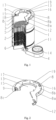
- An exemplary boiler incorporates a jacket 1 with a package of vertical fume pipes 2 mounted inside it, where on the one side the pipes are connected to the combustion chamber 3, and on the other side to a condensate accumulation bowl 4.
- the fume pipes 2 are mounted in the sieve bottoms: upper 5 and lower 6.
- the combustion chamber 3 is placed inside the jacket 1, in its top part.
- the upper sieve bottom 5 forms the bottom of the combustion chamber 3.
- the inside of the jacket 1 forms the main chamber 7 for the boiler water in which the fume pipes 2 and the combustion chamber 3 are immersed.
- the combustion chamber 3 and the jacket 1 are closed with a lid 8.
- the lid 8 features two plates: the inner plate 8a which is connected to the combustion chamber 3, and the outer plate 8b which is situated above the inner plate 8a.
- the said plates 8a, 8b are placed at a distance to each other and connected to each other via the side wall 8c, so that the inner plate 8a extends outside beyond the side wall 8c.
- the outer plate 8b of the lid 8 is connected to the jacket 1, whereas between the outer plate 8a and the jacket 1 is a slit 18 for the flow of the boiler water, and the side wall 8c of the lid 8 features openings 19 which link the main chamber 7 for the boiler water to the additional chamber 9 for the boiler water.
- the outlet stub pipe 12 for the boiler water is mounted on the side wall of the jacket 1.
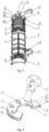
- the inner plate 8a of the lid 8 is connected to the jacket 1 and features one or more openings 10 which link the main chamber 7 for the boiler water to the additional chamber 9 for the boiler water.
- Mounted in the outer plate 8b of the lid 8 is an outlet stub pipe 12 for the boiler water.
- the inlet stub pipe 11 for the boiler water is placed in the bottom part of the jacket 1.
- the lid 8 is fitted with an opening 13 for the burner, socket 15 for an ionisation probe to measure the current flowing through the flame and detect whether the flame continues to burn in the burner, socket 16 for an ignition electrode which generates a sparkle to the ground and is responsible for igniting the gas on the boiler burner, and socket 17 for the viewing device which makes it possible to check visually through observation whether the flame on the burner continues to burn.
- the jacket 1 is fitted with an outlet stub pipe 14 for the fumes.
- the lid 8 is integrated with the jacket and combustion chamber via a welded connection.
- the boiler water circulation in the solution according to the first embodiment of the invention is as follows. Boiler water supplied to the main chamber 7 via the inlet stub pipe 11 flows towards the lid 8 in the direction opposite to the direction of flow of the fumes in the fume pipes 2, and while flowing, the water washes around the hot fume pipes 2, whereupon it washes around the combustion chamber 3 and via the slit 18 it flows onto the extending part of the inner plate 8a, following which, through the openings 19 in the side wall 8c of the lid 8 it flows into the additional chamber 9 from where it is drawn through the outlet stub pipe 12 located in the top part of the jacket.
- the boiler water circulation in the second embodiment differs from the circulation described in the first embodiment in that the boiler water flows into the additional chamber 9 through the opening(s) 10 in the inner plate 8a of the lid 8, from where it is drawn through the outlet pipe 12 located in the outer plate 8a of the lid 8.
Landscapes
- Engineering & Computer Science (AREA)
- Physics & Mathematics (AREA)
- Thermal Sciences (AREA)
- Chemical & Material Sciences (AREA)
- Combustion & Propulsion (AREA)
- Mechanical Engineering (AREA)
- General Engineering & Computer Science (AREA)
- Housings, Intake/Discharge, And Installation Of Fluid Heaters (AREA)
- Heat-Pump Type And Storage Water Heaters (AREA)
- Combustion Of Fluid Fuel (AREA)
Claims (6)
- Kessel mit einer Verbrennungskammer (3) und einem Mantel (1), in dem ein Paket von vertikalen Rauchrohren (2) angeordnet ist, wobei die Rohre (2) einerseits mit der Verbrennungskammer (3) verbunden sind, die sich innerhalb des Mantel (1) befindet, und wobei die Verbrennungskammer (3) durch einen Deckel (8) verschlossen ist, der mit einer Öffnung (13) für einen Brenner versehen ist, und andererseits Rohre (2) an einer Wanne (4) für Kondensat angeschlossen sind, wobei der Kessel außerdem mit einem Einlass- und einer Auslassstutzen (11, 12) fürs Kesselwasser und einem Auslassstutzen (14) für das Rauchgas versehen ist, und wobei der Hohlraum des Mantels (1) die Hauptkammer (7) für das Kesselwasser bildet, wobei der Deckel (8) aus zwei Platten besteht, nämlich aus einer äußeren Platte (8b) und einer inneren Platte (8a), die mit der Verbrennungskammer (3) verbunden ist, wobei die vorgenannten Platten (8a, 8b) in einem Abstand voneinander aufgebaut und durch eine Seitenwand (8c) miteinander verbunden sind, dadurch gekennzeichnet, dass zwischen den erwähnten Platten (8a, 8b) auf der Innenseite der Seitenwand (8c) des Deckels (8) eine zusätzliche Kammer (9) für das Kesselwasser herausgebildet ist, die mit der Hauptkammer (7) für das Kesselwasser verbunden ist, wobei die innere Platte (8a) des Deckels (8) gegenüber der Seitenwand (8c) des Deckels (8) nach außen hinausragt.
- Kessel nach Anspruch 1, dadurch gekennzeichnet, dass die äußere Platte (8b) des Deckels (8) mit dem Mantel (1) verbunden ist, während zwischen der inneren Platte (8a) und dem Mantel (1) ein Spalt (18) herausgebildet ist und in der Seitenwand (8c) des Deckels (8) Aussparrungen (19) vorhanden sind, die die Hauptkammer (7) für das Kesselwasser mit der zusätzliche Kammer (9) für das Kesselwasser verbinden.
- Kessel nach Anspruch 2, dadurch gekennzeichnet, dass am Mantel (1) ein Auslassstutzen (12) für Kesselwasser vorhanden ist.
- Kessel nach Anspruch 1, dadurch gekennzeichnet, dass die innere Platte (8a) des Deckels (8) mit dem Mantel (1) verbunden ist und mit mindestens einer Öffnung (10) versehen ist, die die Hauptkammer (7) für Kesselwasser mit der zusätzliche Kammer (9) für Kesselwasser verbindet.
- Kessel nach Anspruch 4, dadurch gekennzeichnet, dass in der äußeren Platte (8b) des Deckels (8) ein Auslassstutzen (12) für Kesselwasser vorhanden ist.
- Kessel nach Anspruch 2 oder 4, dadurch gekennzeichnet, dass der Deckel (8) durchs Schweißen mit dem Mantel (1) verbunden ist.
Applications Claiming Priority (1)
| Application Number | Priority Date | Filing Date | Title |
|---|---|---|---|
| PL438974A PL247159B1 (pl) | 2021-09-17 | 2021-09-17 | Kocioł grzewczy |
Publications (2)
| Publication Number | Publication Date |
|---|---|
| EP4151923A1 EP4151923A1 (de) | 2023-03-22 |
| EP4151923B1 true EP4151923B1 (de) | 2025-03-19 |
Family
ID=83598451
Family Applications (1)
| Application Number | Title | Priority Date | Filing Date |
|---|---|---|---|
| EP22460043.7A Active EP4151923B1 (de) | 2021-09-17 | 2022-09-15 | Kessel |
Country Status (3)
| Country | Link |
|---|---|
| EP (1) | EP4151923B1 (de) |
| ES (1) | ES3033713T3 (de) |
| PL (2) | PL247159B1 (de) |
Family Cites Families (6)
| Publication number | Priority date | Publication date | Assignee | Title |
|---|---|---|---|---|
| EP0926439A3 (de) | 1997-12-23 | 2000-07-12 | Renato Montini | Gasheizkessel |
| US8844472B2 (en) * | 2009-12-22 | 2014-09-30 | Lochinvar, Llc | Fire tube heater |
| PL216290B1 (pl) | 2010-10-01 | 2014-03-31 | Aic Społka Akcyjna | Wymiennik ciepła |
| US9097436B1 (en) * | 2010-12-27 | 2015-08-04 | Lochinvar, Llc | Integrated dual chamber burner with remote communicating flame strip |
| PL220726B1 (pl) * | 2011-09-29 | 2015-12-31 | Aic Spółka Akcyjna | Wymiennik ciepła do bojlera kondensacyjnego |
| US11231206B2 (en) * | 2020-01-03 | 2022-01-25 | The Marley Company Llc | Counter balanced lid |
-
2021
- 2021-09-17 PL PL438974A patent/PL247159B1/pl unknown
-
2022
- 2022-09-15 EP EP22460043.7A patent/EP4151923B1/de active Active
- 2022-09-15 ES ES22460043T patent/ES3033713T3/es active Active
- 2022-09-15 PL PL22460043.7T patent/PL4151923T3/pl unknown
Also Published As
| Publication number | Publication date |
|---|---|
| EP4151923A1 (de) | 2023-03-22 |
| PL247159B1 (pl) | 2025-05-19 |
| ES3033713T3 (en) | 2025-08-07 |
| PL438974A1 (pl) | 2023-03-20 |
| PL4151923T3 (pl) | 2025-07-07 |
Similar Documents
| Publication | Publication Date | Title |
|---|---|---|
| AU2007200275B2 (en) | High efficiency, wet-base, dowfired multi-pass water heater | |
| US4723513A (en) | Gas water heater/boiler | |
| US4793800A (en) | Gas water heater/boiler | |
| KR100879189B1 (ko) | 이중 튜브 번들을 갖는 응축 열교환기 | |
| CA2629127A1 (en) | Inwardly firing burner and uses thereof | |
| US4949680A (en) | Water heater having filling dip tube | |
| PT1776904E (pt) | Processo e dispositivo para a preparação e distribuição de uma bebida de chocolate | |
| PL220726B1 (pl) | Wymiennik ciepła do bojlera kondensacyjnego | |
| PT2006135145W (pt) | Caldeira de água quente, do tipo de dupla permuta de calor, formada por partes distintas | |
| JP5141171B2 (ja) | ボイラ | |
| JP5141142B2 (ja) | ボイラ | |
| EA019291B1 (ru) | Конденсационный котел с дымогарными трубами для нагрева воды | |
| EP2965022B1 (de) | Wärmetauscher | |
| MXPA06010116A (es) | Dispositivo de calentamiento/almacenamiento de fluido caldeado por combustible de un solo paso. | |
| EP4151923A1 (de) | Kessel | |
| US20040139929A1 (en) | Dual function high efficiency water heater | |
| KR100798629B1 (ko) | 연소가스 다중통과구조를 갖는 보일러 열교환장치 | |
| EP0759527A1 (de) | Wärmetauscher | |
| KR100689145B1 (ko) | 보일러의 열교환장치 | |
| CN115899774B (zh) | 一种具有水汽系统的燃气炉灶 | |
| KR100648965B1 (ko) | 선박용 보일러 | |
| PL229351B1 (pl) | Poszycie rurowego wymiennika ciepła | |
| RU2327082C1 (ru) | Водогрейный котел | |
| WO2016003300A1 (en) | Combustion chamber for a gas-fired heat exchanger | |
| AU2007299586A1 (en) | An inclined heat exchanger |
Legal Events
| Date | Code | Title | Description |
|---|---|---|---|
| PUAI | Public reference made under article 153(3) epc to a published international application that has entered the european phase |
Free format text: ORIGINAL CODE: 0009012 |
|
| STAA | Information on the status of an ep patent application or granted ep patent |
Free format text: STATUS: THE APPLICATION HAS BEEN PUBLISHED |
|
| AK | Designated contracting states |
Kind code of ref document: A1 Designated state(s): AL AT BE BG CH CY CZ DE DK EE ES FI FR GB GR HR HU IE IS IT LI LT LU LV MC MK MT NL NO PL PT RO RS SE SI SK SM TR |
|
| STAA | Information on the status of an ep patent application or granted ep patent |
Free format text: STATUS: REQUEST FOR EXAMINATION WAS MADE |
|
| 17P | Request for examination filed |
Effective date: 20230911 |
|
| RBV | Designated contracting states (corrected) |
Designated state(s): AL AT BE BG CH CY CZ DE DK EE ES FI FR GB GR HR HU IE IS IT LI LT LU LV MC MK MT NL NO PL PT RO RS SE SI SK SM TR |
|
| GRAP | Despatch of communication of intention to grant a patent |
Free format text: ORIGINAL CODE: EPIDOSNIGR1 |
|
| STAA | Information on the status of an ep patent application or granted ep patent |
Free format text: STATUS: GRANT OF PATENT IS INTENDED |
|
| RIC1 | Information provided on ipc code assigned before grant |
Ipc: F24H 9/1836 20220101ALI20240920BHEP Ipc: F24H 9/02 20060101ALI20240920BHEP Ipc: F24H 9/00 20220101ALI20240920BHEP Ipc: F24H 8/00 20220101ALI20240920BHEP Ipc: F24H 1/44 20220101ALI20240920BHEP Ipc: F24H 1/28 20220101ALI20240920BHEP Ipc: F24H 1/26 20220101AFI20240920BHEP |
|
| INTG | Intention to grant announced |
Effective date: 20241011 |
|
| RIN1 | Information on inventor provided before grant (corrected) |
Inventor name: PACHOLSKI, ADAM Inventor name: KOWALSKI, TOMASZ Inventor name: KUZMA, MARIUSZ |
|
| GRAS | Grant fee paid |
Free format text: ORIGINAL CODE: EPIDOSNIGR3 |
|
| GRAA | (expected) grant |
Free format text: ORIGINAL CODE: 0009210 |
|
| STAA | Information on the status of an ep patent application or granted ep patent |
Free format text: STATUS: THE PATENT HAS BEEN GRANTED |
|
| AK | Designated contracting states |
Kind code of ref document: B1 Designated state(s): AL AT BE BG CH CY CZ DE DK EE ES FI FR GB GR HR HU IE IS IT LI LT LU LV MC MK MT NL NO PL PT RO RS SE SI SK SM TR |
|
| REG | Reference to a national code |
Ref country code: GB Ref legal event code: FG4D |
|
| REG | Reference to a national code |
Ref country code: CH Ref legal event code: EP |
|
| REG | Reference to a national code |
Ref country code: DE Ref legal event code: R096 Ref document number: 602022011959 Country of ref document: DE |
|
| REG | Reference to a national code |
Ref country code: IE Ref legal event code: FG4D |
|
| PG25 | Lapsed in a contracting state [announced via postgrant information from national office to epo] |
Ref country code: RS Free format text: LAPSE BECAUSE OF FAILURE TO SUBMIT A TRANSLATION OF THE DESCRIPTION OR TO PAY THE FEE WITHIN THE PRESCRIBED TIME-LIMIT Effective date: 20250619 |
|
| PG25 | Lapsed in a contracting state [announced via postgrant information from national office to epo] |
Ref country code: FI Free format text: LAPSE BECAUSE OF FAILURE TO SUBMIT A TRANSLATION OF THE DESCRIPTION OR TO PAY THE FEE WITHIN THE PRESCRIBED TIME-LIMIT Effective date: 20250319 |
|
| REG | Reference to a national code |
Ref country code: NL Ref legal event code: FP |
|
| REG | Reference to a national code |
Ref country code: LT Ref legal event code: MG9D |
|
| PG25 | Lapsed in a contracting state [announced via postgrant information from national office to epo] |
Ref country code: NO Free format text: LAPSE BECAUSE OF FAILURE TO SUBMIT A TRANSLATION OF THE DESCRIPTION OR TO PAY THE FEE WITHIN THE PRESCRIBED TIME-LIMIT Effective date: 20250619 |
|
| PG25 | Lapsed in a contracting state [announced via postgrant information from national office to epo] |
Ref country code: HR Free format text: LAPSE BECAUSE OF FAILURE TO SUBMIT A TRANSLATION OF THE DESCRIPTION OR TO PAY THE FEE WITHIN THE PRESCRIBED TIME-LIMIT Effective date: 20250319 |
|
| PG25 | Lapsed in a contracting state [announced via postgrant information from national office to epo] |
Ref country code: LV Free format text: LAPSE BECAUSE OF FAILURE TO SUBMIT A TRANSLATION OF THE DESCRIPTION OR TO PAY THE FEE WITHIN THE PRESCRIBED TIME-LIMIT Effective date: 20250319 |
|
| PG25 | Lapsed in a contracting state [announced via postgrant information from national office to epo] |
Ref country code: BG Free format text: LAPSE BECAUSE OF FAILURE TO SUBMIT A TRANSLATION OF THE DESCRIPTION OR TO PAY THE FEE WITHIN THE PRESCRIBED TIME-LIMIT Effective date: 20250319 Ref country code: GR Free format text: LAPSE BECAUSE OF FAILURE TO SUBMIT A TRANSLATION OF THE DESCRIPTION OR TO PAY THE FEE WITHIN THE PRESCRIBED TIME-LIMIT Effective date: 20250620 |
|
| REG | Reference to a national code |
Ref country code: ES Ref legal event code: FG2A Ref document number: 3033713 Country of ref document: ES Kind code of ref document: T3 Effective date: 20250807 |
|
| REG | Reference to a national code |
Ref country code: AT Ref legal event code: MK05 Ref document number: 1777238 Country of ref document: AT Kind code of ref document: T Effective date: 20250319 |
|
| PG25 | Lapsed in a contracting state [announced via postgrant information from national office to epo] |
Ref country code: SE Free format text: LAPSE BECAUSE OF FAILURE TO SUBMIT A TRANSLATION OF THE DESCRIPTION OR TO PAY THE FEE WITHIN THE PRESCRIBED TIME-LIMIT Effective date: 20250319 |
|
| PG25 | Lapsed in a contracting state [announced via postgrant information from national office to epo] |
Ref country code: SM Free format text: LAPSE BECAUSE OF FAILURE TO SUBMIT A TRANSLATION OF THE DESCRIPTION OR TO PAY THE FEE WITHIN THE PRESCRIBED TIME-LIMIT Effective date: 20250319 |
|
| PG25 | Lapsed in a contracting state [announced via postgrant information from national office to epo] |
Ref country code: PT Free format text: LAPSE BECAUSE OF FAILURE TO SUBMIT A TRANSLATION OF THE DESCRIPTION OR TO PAY THE FEE WITHIN THE PRESCRIBED TIME-LIMIT Effective date: 20250721 |
|
| PGFP | Annual fee paid to national office [announced via postgrant information from national office to epo] |
Ref country code: NL Payment date: 20250902 Year of fee payment: 4 Ref country code: PL Payment date: 20250908 Year of fee payment: 4 |
|
| PG25 | Lapsed in a contracting state [announced via postgrant information from national office to epo] |
Ref country code: AT Free format text: LAPSE BECAUSE OF FAILURE TO SUBMIT A TRANSLATION OF THE DESCRIPTION OR TO PAY THE FEE WITHIN THE PRESCRIBED TIME-LIMIT Effective date: 20250319 |
|
| PGFP | Annual fee paid to national office [announced via postgrant information from national office to epo] |
Ref country code: FR Payment date: 20250902 Year of fee payment: 4 |
|
| PG25 | Lapsed in a contracting state [announced via postgrant information from national office to epo] |
Ref country code: CZ Free format text: LAPSE BECAUSE OF FAILURE TO SUBMIT A TRANSLATION OF THE DESCRIPTION OR TO PAY THE FEE WITHIN THE PRESCRIBED TIME-LIMIT Effective date: 20250319 Ref country code: EE Free format text: LAPSE BECAUSE OF FAILURE TO SUBMIT A TRANSLATION OF THE DESCRIPTION OR TO PAY THE FEE WITHIN THE PRESCRIBED TIME-LIMIT Effective date: 20250319 |
|
| PG25 | Lapsed in a contracting state [announced via postgrant information from national office to epo] |
Ref country code: RO Free format text: LAPSE BECAUSE OF FAILURE TO SUBMIT A TRANSLATION OF THE DESCRIPTION OR TO PAY THE FEE WITHIN THE PRESCRIBED TIME-LIMIT Effective date: 20250319 |
|
| PG25 | Lapsed in a contracting state [announced via postgrant information from national office to epo] |
Ref country code: SK Free format text: LAPSE BECAUSE OF FAILURE TO SUBMIT A TRANSLATION OF THE DESCRIPTION OR TO PAY THE FEE WITHIN THE PRESCRIBED TIME-LIMIT Effective date: 20250319 |
|
| PG25 | Lapsed in a contracting state [announced via postgrant information from national office to epo] |
Ref country code: IS Free format text: LAPSE BECAUSE OF FAILURE TO SUBMIT A TRANSLATION OF THE DESCRIPTION OR TO PAY THE FEE WITHIN THE PRESCRIBED TIME-LIMIT Effective date: 20250719 |
|
| REG | Reference to a national code |
Ref country code: DE Ref legal event code: R097 Ref document number: 602022011959 Country of ref document: DE |
|
| PG25 | Lapsed in a contracting state [announced via postgrant information from national office to epo] |
Ref country code: DK Free format text: LAPSE BECAUSE OF FAILURE TO SUBMIT A TRANSLATION OF THE DESCRIPTION OR TO PAY THE FEE WITHIN THE PRESCRIBED TIME-LIMIT Effective date: 20250319 |
|
| PGFP | Annual fee paid to national office [announced via postgrant information from national office to epo] |
Ref country code: IT Payment date: 20250930 Year of fee payment: 4 |
|
| PLBE | No opposition filed within time limit |
Free format text: ORIGINAL CODE: 0009261 |
|
| STAA | Information on the status of an ep patent application or granted ep patent |
Free format text: STATUS: NO OPPOSITION FILED WITHIN TIME LIMIT |
|
| REG | Reference to a national code |
Ref country code: CH Ref legal event code: L10 Free format text: ST27 STATUS EVENT CODE: U-0-0-L10-L00 (AS PROVIDED BY THE NATIONAL OFFICE) Effective date: 20260128 |
|
| PGFP | Annual fee paid to national office [announced via postgrant information from national office to epo] |
Ref country code: ES Payment date: 20251001 Year of fee payment: 4 |
|
| 26N | No opposition filed |
Effective date: 20251222 |
|
| REG | Reference to a national code |
Ref country code: DE Ref legal event code: R119 Ref document number: 602022011959 Country of ref document: DE |
|
| REG | Reference to a national code |
Ref country code: CH Ref legal event code: H13 Free format text: ST27 STATUS EVENT CODE: U-0-0-H10-H13 (AS PROVIDED BY THE NATIONAL OFFICE) Effective date: 20260425 |
|
| PG25 | Lapsed in a contracting state [announced via postgrant information from national office to epo] |
Ref country code: LU Free format text: LAPSE BECAUSE OF NON-PAYMENT OF DUE FEES Effective date: 20250915 |
|
| REG | Reference to a national code |
Ref country code: BE Ref legal event code: MM Effective date: 20250930 |
|
| PG25 | Lapsed in a contracting state [announced via postgrant information from national office to epo] |
Ref country code: LT Free format text: LAPSE BECAUSE OF FAILURE TO SUBMIT A TRANSLATION OF THE DESCRIPTION OR TO PAY THE FEE WITHIN THE PRESCRIBED TIME-LIMIT Effective date: 20250319 |
|
| PG25 | Lapsed in a contracting state [announced via postgrant information from national office to epo] |
Ref country code: MC Free format text: LAPSE BECAUSE OF FAILURE TO SUBMIT A TRANSLATION OF THE DESCRIPTION OR TO PAY THE FEE WITHIN THE PRESCRIBED TIME-LIMIT Effective date: 20250319 |
|
| PG25 | Lapsed in a contracting state [announced via postgrant information from national office to epo] |
Ref country code: DE Free format text: LAPSE BECAUSE OF NON-PAYMENT OF DUE FEES Effective date: 20260401 |
|
| PG25 | Lapsed in a contracting state [announced via postgrant information from national office to epo] |
Ref country code: BE Free format text: LAPSE BECAUSE OF NON-PAYMENT OF DUE FEES Effective date: 20250930 Ref country code: CH Free format text: LAPSE BECAUSE OF NON-PAYMENT OF DUE FEES Effective date: 20250930 Ref country code: IE Free format text: LAPSE BECAUSE OF NON-PAYMENT OF DUE FEES Effective date: 20250915 |