EP4151796B1 - Kleidungsdämpfer mit abnehmbarem wasserbehälter - Google Patents
Kleidungsdämpfer mit abnehmbarem wasserbehälter Download PDFInfo
- Publication number
- EP4151796B1 EP4151796B1 EP21197067.8A EP21197067A EP4151796B1 EP 4151796 B1 EP4151796 B1 EP 4151796B1 EP 21197067 A EP21197067 A EP 21197067A EP 4151796 B1 EP4151796 B1 EP 4151796B1
- Authority
- EP
- European Patent Office
- Prior art keywords
- water tank
- handle
- door assembly
- garment steamer
- water inlet
- Prior art date
- Legal status (The legal status is an assumption and is not a legal conclusion. Google has not performed a legal analysis and makes no representation as to the accuracy of the status listed.)
- Active
Links
Images



Classifications
-
- D—TEXTILES; PAPER
- D06—TREATMENT OF TEXTILES OR THE LIKE; LAUNDERING; FLEXIBLE MATERIALS NOT OTHERWISE PROVIDED FOR
- D06F—LAUNDERING, DRYING, IRONING, PRESSING OR FOLDING TEXTILE ARTICLES
- D06F73/00—Apparatus for smoothing or removing creases from garments or other textile articles by formers, cores, stretchers, or internal frames, with the application of heat or steam
-
- D—TEXTILES; PAPER
- D06—TREATMENT OF TEXTILES OR THE LIKE; LAUNDERING; FLEXIBLE MATERIALS NOT OTHERWISE PROVIDED FOR
- D06F—LAUNDERING, DRYING, IRONING, PRESSING OR FOLDING TEXTILE ARTICLES
- D06F87/00—Apparatus for moistening or otherwise conditioning the article to be ironed or pressed
Definitions
- the invention relates to a garment steamer, and in particular to the refillable water tank included in such a garment steamer.
- the invention may be used in the field of garment care.
- Garment steamers typically comprise a steam generator and a water tank for containing water to be supplied to the steam generator.
- Handheld garment steamers can comprise a steam generator and a detachable water tank integrated into a single portable hand unit.
- the water tank has a water inlet for permitting filling/refilling and emptying of the water tank.
- the water inlet can be closed by a door, e.g. a cap, to retain water in the water tank.
- the water tank typically has a base, or bottom end portion.
- the water inlet is, for example, arranged in the base. Due to limited space at the base of the water tank, the water inlet and the door tend to be relatively small, which can hamper filling/refilling and emptying of the water tank. A more conveniently located water inlet and door, e.g. which permits the water inlet to be made larger, would be desirable for facilitating refilling/filling and emptying of the water tank.
- CN 210 766 066 U discloses a water tank disassembling and assembling structure for a handheld ironing machine.
- the garment steamer according to the invention comprises
- the user is first required to detach the water tank from the handle in order to be able to fill/refill the water tank via the water inlet.
- This may assist to improve user safety because the risk of splashing of the handle of the garment steamer, which can include electrical components for operation of the steam generator, while filling/refilling or emptying the water tank is lessened.
- the door assembly and the handle are, in at least some embodiments, adapted and cooperate with each other such that the door assembly is immobilized in the first position when the water tank is attached to the handle, with the door assembly being permitted to move to expose the water inlet when the water tank is detached from the handle.
- the second position can, for instance, be a fully open position in which the door assembly is moved to completely expose the water inlet.
- the door assembly is pivotable relative to the water tank to expose the water inlet when the water tank is detached from the handle.
- Such a pivotable door assembly may facilitate filling/refilling and emptying of the water tank when the water tank is detached from the handle.
- the pivotable door assembly can provide easier access to fill/refill and empty the water tank than, for instance, a screw cap which requires multiple turns to remove.
- the handle comprises a portion arranged to contact a part of the door assembly such that the door assembly is immobilized in the first position when the water tank is attached to the handle.
- This portion of the handle can be regarded as a stopper element which, when the water tank is attached to the handle, immobilizes the door assembly in the first position.
- the portion is preferably defined by an edge portion of the handle, with the edge portion abutting the part of the door assembly to prevent pivoting of the door assembly from the first position when the water tank is attached to the handle.
- the water tank comprises:
- Arranging the water inlet in the side portion of the water tank can facilitate filling/refilling and emptying, for example by permitting the water inlet to be made larger than if the water inlet were to be arranged in one of the end portions.
- a side portion-arranged water inlet can risk damage to the garment steamer and/or safety issues when such a water inlet is openable to admit water while the water tank remains attached to the handle.
- the side portion-arranged water inlet in the case of the present disclosure, is advantageously enabled by such filling/refilling or emptying being required to take place when the water tank is detached from the handle.
- the door assembly comprises a seal member for sealing the water inlet when the door assembly is in the first position.
- the door assembly comprises a door and a seal member attached to the door for sealing the water inlet when the door assembly is in the first position.
- the seal member can assist the door assembly to fluidly close the water inlet when the door assembly is in the first position.
- the seal member is preferably formed from an elastomeric material.
- an elastomeric material can resiliently deform, and thereby assist the door assembly to fluidly close the water inlet when the door assembly is in the first position.
- the seal member comprises a protrusion
- the door door comprises an engagement member whose shape complements the protrusion thereby to engage and receive the seal member
- the seal member further comprises an outer groove adapted to match an inner periphery of the water inlet.
- the sealing of the water inlet in the first position can be improved.
- the outer groove extends around an outer periphery of the seal member.
- the outer groove can, for instance, extend around the protrusion.
- the outer groove can enhance the capability of the seal member to deform/flex when the door assembly is being opened, thereby reducing the risk of the seal member becoming detached from the door.
- the outer groove also improves the sealing of the water inlet in the first position, as explained above.
- the garment steamer comprises a threaded coupling or a bayonet coupling for detachably coupling the water tank and the handle.
- Such a coupling can assist to minimise the risk of the water tank becoming dislodged, or unintentionally disconnected from the handle, if the user attempts to force the door assembly open, e.g. to the second position, without first detaching the water tank from the handle.
- the garment steamer is a handheld garment steamer.
- the steam generator and the detachable water tank are integrated into a single portable hand unit when the garment steamer is such a handheld garment steamer.
- Figs.1A and 1B provide views of a garment steamer 100 comprising a steam generator 102 for generating steam.
- the garment steamer 100 further comprises a water tank 104 for containing water to be supplied to the steam generator.
- Water can be transported from the water tank 104 to the steam generator via a suitable water dosing assembly (not visible in Figs. 1A and 1B ).
- the water tank 104 has a water inlet 106 for receiving water.
- the water tank 104 can be filled/refilled, and also emptied, via the water inlet 106.
- the water tank 104 also comprises a door assembly 108, 109 adapted to take a first position P1 in which the water inlet 106 is fluidly closed, and a second position P2 in which the water inlet 106 is opened.
- the door assembly 108, 109 comprises a seal member 109 for sealing the water inlet 106 when the door assembly is in the first position P1.
- the seal member 109 can thus assist the door assembly 108, 109 to fluidly close the water inlet 106 when the door assembly 108, 109 is in the first position P1.
- the seal member109 can be formed of any suitable material capable of minimising or preventing water leakage from the water tank via the water inlet 106 when the door assembly 108, 109 is in the first position P1.
- the seal member is formed from an elastomeric material, such as rubber, e.g. silicone rubber.
- the door assembly 108, 109 can include, or in some examples be, a door 108.
- seal member 109 can, for instance, be secured to the door 108, as will be explained in more detail herein below.
- the door 108 can be formed of any suitable material, such as a plastic material, e.g. an engineering thermoplastic.
- the garment steamer 100 comprises a handle 110.
- the handle 110 permits the user to hold the garment steamer 100.
- the handle 110 can also function as a casing for some of the components, in particular electrical components for controlling the steam generator 102.
- the handle 110 can comprise a suitable casing material, such as an engineering thermoplastic.
- the garment steamer 100 is a handheld garment steamer.
- the steam generator 102 and the water tank 104 are integrated into a single portable hand unit when the garment steamer 100 is such a handheld garment steamer.
- the water tank 104 is detachable from the handle 110.
- Figs.1A and 1B show the garment steamer 100 with the water tank 104 attached to the handle 110.
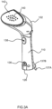
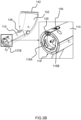
- Figs.2A and 2B depict the water tank 104 detached from the handle 110.
- Figs.3A and 3B show the garment steamer 100 without the water tank 104, in other words after detachment of the water tank 104.
- Detachably coupling the water tank 104 and the handle 110 can be achieved in any suitable manner.
- a threaded coupling or a bayonet coupling detachably couples the water tank 104 and the handle 110.
- coupling members 112A, 112B are provided at an upper end portion 114A of the water tank 104, as shown in Figs.2A and 2B . These coupling members 112A, 112B each engage with one of the complementary slots 116A, 116B provided at a lower end 118 of the handle 110, as shown in Fig.3B .
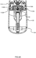
- Fig.4A shows the water tank 104 attached to the handle 110 by the coupling members 112A, 112B engaging the slots 116A, 116B.
- the door assembly 108, 109 and the handle 110 are adapted and cooperate with each other such that the handle 110 maintains the door assembly 108, 109 in the first position P1 when the water tank 104 is attached to the handle 110.
- the user is first required to detach the water tank 104 from the handle 110 in order to be able to fill/refill and empty the water tank 104 via the water inlet 106.
- This may assist to improve user safety because the risk of splashing of the handle 110 of the garment steamer 100, which can include electrical components for operation of the steam generator 102, while filling/refilling and emptying the water tank 104 is lessened.
- the door assembly 108, 109 can be regarded as cooperating with the handle 110 of the garment steamer 100 such that the door assembly 108, 109 cannot be opened while the water tank 104 is attached thereto.
- the door assembly 108, 109 and the handle 110 are, in at least some embodiments, adapted and cooperate with each other such that the door assembly 108, 109 is immobilized or locked in the first position when the water tank 104 is attached to the handle 110, with the door assembly 108, 109 being permitted to move to expose the water inlet 106 when the water tank 104 is detached from the handle 110.
- the water tank 104 is coupled to the handle 110 via the above-described threaded or bayonet coupling
- such a coupling can assist to minimise the risk of the water tank 104 becoming dislodged, or unintentionally disconnected from the handle 110, if the user attempts to force the door assembly 108, 109 open, e.g. to the second position P2, without first detaching the water tank 104 from the handle 110.
- the water tank 104 comprises the upper end portion 114A, a bottom end portion 114B opposite the upper end portion 114A, and a side portion 120 extending between the upper and bottom end portions 114A, 114B.
- the water inlet 106 is preferably arranged in the side portion 120.
- Arranging the water inlet 106 in the side portion 120 of the water tank 104 can facilitate filling/refilling and emptying, for example by permitting the water inlet 106 to be made larger than if the water inlet were to be arranged in one of the end portions 114A, 114B.
- a side portion-arranged water inlet 106 can risk damage to the garment steamer 100 and/or safety issues when such a water inlet 106 is openable to admit or release water while the water tank 104 remains attached to the handle 110. Accordingly, the side portion-arranged water inlet 106 in the case of the present disclosure is advantageously enabled by such filling/refilling or emptying being required to take place when the water tank 104 is detached from the handle 110.
- the water tank 104 is preferably axially symmetric, or substantially axially symmetric, about an axis A1 extending towards the handle 110 through the centre of the water tank 104.
- the axis A1 is shown in Fig.1B .
- substantially axially symmetric may reflect the presence of the water inlet 106 and the door assembly 108, 109, for example at the above-described side portion 120 of the water tank 104, which may disrupt the axial symmetry without altering the overall shape of the water tank 104.
- the door assembly 108, 109 is preferably arranged at or proximal to the upper end portion 114A of the water tank 104 where the water tank 104 attaches to the handle 110.
- This arrangement is facilitated by the above-described adaptation and cooperation of the water tank 104 and the handle 110 because the latter alleviates the potential safety risk, for example of electric shock, associated with water spill onto components, such as a power connection, proximal to the upper end portion 114A of the water tank 104.
- the door assembly 108, 109 is rotatable.
- the door assembly 108, 109 is preferably pivotable relative to the water tank 104 to expose the water inlet 106 when the water tank 104 is detached from the handle 110.
- Such a pivotable door assembly 108, 109 may facilitate filling/refilling and emptying of the water tank 104 when the water tank 104 is detached from the handle 110.
- the pivotable door assembly 108, 109 can provide easier access to fill/refill the water tank 104 than, for instance, a screw cap which requires multiple turns to remove.
- the door assembly 108, 109 is pivotable such that the door assembly 108, 109 swings outwardly away from the water tank 104, as shown in Fig.2B .
- the water tank 104 preferably comprises a tank housing 122, and a pivot coupling 124 pivotably couples the door assembly 108, 109 to the tank housing 122.
- the pivot coupling 124 is thus arranged to permit pivoting, e.g. outward pivoting away from the water tank 104, of the door assembly 108, 109 relative to the tank housing 122 to expose the water inlet 106 when the water tank 104 is detached from the handle 110.
- the handle 110 comprises a portion 126 arranged to contact a part 128 of the door assembly 108, 109 such that the door assembly 108, 109 is immobilized in the first position P1 when the water tank 104 is attached to the handle 110.
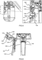
- This portion 126 of the handle 110 can be regarded as a stopper element which, when the water tank 104 is attached to the handle 110, immobilizes the door assembly 108, 109 in the first position P1, as shown in Fig.5 .
- the portion 126 can be defined by an edge portion of the handle 110. This edge portion 126 abuts the part 128 of the door assembly 108, 109 to prevent pivoting of the door assembly 108, 109 from the first position P1 to expose the water inlet 106 when the water tank 104 is attached to the handle 110.
- the edge portion 126 of the handle 110 no longer abuts the part 128 of the door assembly 108, 109, and the door assembly 108, 109 can correspondingly be moved, in this case pivoted, to expose the water inlet 106.
- the door assembly 108, 109 can take the second position P2.
- the part 128 of the door assembly 108, 109 can be in contact with the edge portion 126 of the handle 110 when the water tank 104 is attached to the handle 110.
- this relatively small gap does not hamper the function of the edge portion 126 and the part 128 to prevent movement, e.g. pivoting, of the door assembly 108, 109 from the first position P1 to expose the water inlet 106 when the water tank 104 is attached to the handle 110.
- the pivot coupling 124 is positioned proximal to the upper end portion 114A, and arranged such that the door assembly 108, 109 swings or rotates outwards from the water tank 104 and upwards towards the upper end portion 114A when the door assembly 108, 109 is moving from the first, fully/fluidly closed, position P1 to the second, open, position P2.
- the edge portion 126 is included in the lower end 118 of the handle 110.
- a top part 128, of the door assembly 108, 109 being in contact with the edge portion 126, or the above-described relatively small gap being present between the top part 128 and the edge portion 126, opening of the door assembly 108, 109 when the water tank 104 is attached to the handle 110 is prevented.
- the user has to detach the water tank 104 from the handle 110 in order to access the water inlet 106 for filling/refilling or emptying the water tank 104.
- the second position P2 can be regarded as a position in which the door assembly 108, 109 is moved sufficiently to expose the water inlet 106 for filling/refilling and emptying the water tank 104.
- the second position P2 can, for instance, be a fully open position in which the door assembly 108, 109 is moved to completely expose the water inlet 106.
- An example of this is depicted in Fig.6 .
- the door assembly 108, 109 further comprises a door holding member (not shown) arranged to maintain the door assembly 108, 109 in an open position, such as the fully open position shown in Fig.6 or a partially open position intermediate between the first, closed, position P1 and the fully open position.
- a door holding member can improve user convenience due to the user not being required to themselves hold the door assembly 108, 109 open during filling/refilling or emptying of the water tank 104.
- the door holding member comprises, or is in the form of, a protrusion arranged such that a portion of the door assembly 108, 109 rests against the protrusion while the door assembly 108, 109 is in the open position, such as the second position P2, to maintain the door assembly 108, 109 in the open position.
- the protrusion still permits the door assembly 108, 109 to be moved, e.g. pivoted, towards the open or closed positions by manual forcing of the portion of the door assembly 108, 109 past the protrusion.
- the seal member 109 comprises a protrusion 130
- the door 108 includes an engagement member 132 whose shape complements the protrusion 130 thereby to engage and receive the seal member 109.
- the seal member 109 further comprises an outer groove 134 adapted to match, e.g. follow the shape of, an inner periphery of the water inlet 106.
- the sealing of the water inlet 106 in the first position P1 can be improved.
- the outer groove 134 extends around an outer periphery of the seal member 109.
- the outer groove 134 can, for instance, extend around the protrusion 130.
- the outer groove 134 can enhance the capability of the seal member 109 to deform/flex when the door assembly 108, 109 is being opened, thereby reducing the risk of the seal member 109 becoming detached from the door 108.
- the garment steamer 100 can be used to steam garments.
- the garment steamer 100 can be turned on via the power switch 136, e.g. following connecting the garment steamer 100 to a mains supply of electricity via power cord 137A.
- the power cord 137A connects to the handle 110 via a power cord grommet 137B.
- the power cord grommet 137B can be formed of any suitable material, such as thermoplastic polyurethane.
- the steam supply can be controlled via the steam trigger 138, and the steam generated by the steam generator 102 is supplied to the garment(s) being steamed via one or more steam outlets 140 provided in a treatment plate 142.
- valve arrangement 144 comprises a ball valve, included in the water tank 104, for controlling the flow of water therefrom towards the steam generator 102.
Landscapes
- Engineering & Computer Science (AREA)
- Textile Engineering (AREA)
- Cookers (AREA)
Claims (11)
- Kleidungsdämpfer (100), umfassend:- einen Griff (110) zum Halten des Kleidungsdämpfers,- einen Dampferzeuger (102) zum Erzeugen von Dampf, und- einen Wasserbehälter(104) zum Enthalten von Wasser, das dem Dampferzeuger zuzuführen ist, wobei der Wasserbehälter vom Griff abnehmbar ist, wobei der Wasserbehälter Folgendes umfasst:i) einen Wassereinlass (106) zum Aufnehmen von Wasser,ii) eine Türanordnung (108, 109), die dazu angepasst ist, eine erste Position (P1), in der der Wassereinlass flüssigkeitsdicht verschlossen ist, und eine zweite Position (P2), in der der Wassereinlass geöffnet ist, einzunehmen, dadurch gekennzeichnet, dass die Türanordnung und der Griff so angepasst sind und so miteinander zusammenwirken, dass der Griff die Türanordnung in der ersten Position (P1) hält, wenn der Wasserbehälter an dem Griff angebracht ist.
- Kleidungsdämpfer (100) nach Anspruch 1, wobei die Türanordnung (108, 109) relativ zum Wasserbehälter (104) schwenkbar ist, um den Wassereinlass (106) freizulegen, wenn der Wasserbehälter vom Griff (110) abgenommen ist.
- Kleidungsdämpfer (100) nach Anspruch 1 oder Anspruch 2, wobei der Griff (110) einen Abschnitt (126) umfasst, der dazu angeordnet ist, mit einem Teil (128) der Türanordnung (108, 109) in Kontakt zu kommen, so dass die Türanordnung in der ersten Position (P1) fixiert ist, wenn der Wasserbehälter (104) an dem Griff angebracht ist.
- Kleidungsdämpfer (100) nach Anspruch 3 wie nach Anspruch 2, wobei der Abschnitt (126) durch einen Kantenabschnitt des Griffs (110) definiert ist, wobei der Kantenabschnitt an den Teil (128) der Türanordnung (108, 109) anstößt, um ein Schwenken der Türanordnung aus der ersten Position (P1) zu verhindern, wenn der Wasserbehälter (104) an dem Griff angebracht ist.
- Kleidungsdämpfer (100) nach einem der Ansprüche 1 bis 4, wobei der Wasserbehälter (104) Folgendes umfasst:- einen oberen Endabschnitt (114A), an den der Griff (110) abnehmbar gekoppelt ist,- einen unteren Endabschnitt (114B) gegenüber dem oberen Endabschnitt, und- einen Seitenabschnitt (120), der sich zwischen dem oberen Endabschnitt und dem unteren Endabschnitt erstreckt, wobei der Wassereinlass (106) in dem Seitenabschnitt angeordnet ist.
- Kleidungsdämpfer (100) nach einem der Ansprüche 1 bis 5, wobei die Türanordnung (108, 109) eine Tür (108) und ein an der Tür angebrachtes Dichtungselement (109) zum Abdichten des Wassereinlasses (106) umfasst, wenn sich die Türanordnung in der ersten Position (P1) befindet.
- Kleidungsdämpfer (100) nach Anspruch 6, wobei das Dichtungselement (109) aus einem elastomeren Werkstoff gebildet ist.
- Kleidungsdämpfer (100) nach Anspruch 6 oder Anspruch 7, wobei das Dichtungselement (109) einen Vorsprung (130) umfasst, wobei die Tür ein Eingriffselement (132) umfasst, dessen Form den Vorsprung ergänzt, um dadurch mit dem Dichtungselement in Eingriff zu kommen und es aufzunehmen.
- Kleidungsdämpfer (100) nach Anspruch 8, wobei das Dichtungselement (109) weiter eine Außennut (134) umfasst, die dazu angepasst ist, zu einem Innenumfang des Wassereinlasses (106) zu passen.
- Kleidungsdämpfer (100) nach einem der Ansprüche 1 bis 9, der eine Gewindekupplung oder eine Bajonettkupplung zum abnehmbaren Verbinden des Wasserbehälters (104) und des Griffs (110) umfasst.
- Kleidungsdämpfer (100) nach einem der Ansprüche 1 bis 10, wobei der Kleidungsdämpfer ein handgeführter Kleidungsdämpfer ist.
Priority Applications (2)
| Application Number | Priority Date | Filing Date | Title |
|---|---|---|---|
| PL21197067.8T PL4151796T3 (pl) | 2021-09-16 | 2021-09-16 | Parownica do odzieży zawierająca odłączalny zbiornik na wodę |
| EP21197067.8A EP4151796B1 (de) | 2021-09-16 | 2021-09-16 | Kleidungsdämpfer mit abnehmbarem wasserbehälter |
Applications Claiming Priority (1)
| Application Number | Priority Date | Filing Date | Title |
|---|---|---|---|
| EP21197067.8A EP4151796B1 (de) | 2021-09-16 | 2021-09-16 | Kleidungsdämpfer mit abnehmbarem wasserbehälter |
Publications (2)
| Publication Number | Publication Date |
|---|---|
| EP4151796A1 EP4151796A1 (de) | 2023-03-22 |
| EP4151796B1 true EP4151796B1 (de) | 2024-07-24 |
Family
ID=77801544
Family Applications (1)
| Application Number | Title | Priority Date | Filing Date |
|---|---|---|---|
| EP21197067.8A Active EP4151796B1 (de) | 2021-09-16 | 2021-09-16 | Kleidungsdämpfer mit abnehmbarem wasserbehälter |
Country Status (2)
| Country | Link |
|---|---|
| EP (1) | EP4151796B1 (de) |
| PL (1) | PL4151796T3 (de) |
Family Cites Families (7)
| Publication number | Priority date | Publication date | Assignee | Title |
|---|---|---|---|---|
| EP0104048A3 (de) * | 1982-09-22 | 1985-12-18 | Primeline (Imports) Limited | Elektrisches Gerät mit Wasserbehälter |
| US4496826A (en) * | 1983-02-14 | 1985-01-29 | Leonard Osrow | Hand-held shock-resistant electrolytically heated steam producing apparatus |
| US20050028408A1 (en) * | 2003-08-06 | 2005-02-10 | Tobias Andrew J. | Convertible iron/steamer |
| US20210310182A1 (en) * | 2018-08-09 | 2021-10-07 | Vornado Air, Llc | Collapsible Steamer Apparatus |
| CN209836625U (zh) * | 2019-01-07 | 2019-12-24 | 张海荣 | 一种便携式挂烫机 |
| CN210766066U (zh) * | 2019-07-29 | 2020-06-16 | 浙江华光电器集团有限公司 | 一种手持式熨烫机的水箱拆装结构 |
| US11236463B2 (en) * | 2019-11-21 | 2022-02-01 | Conair Llc | Fabric steamer |
-
2021
- 2021-09-16 EP EP21197067.8A patent/EP4151796B1/de active Active
- 2021-09-16 PL PL21197067.8T patent/PL4151796T3/pl unknown
Also Published As
| Publication number | Publication date |
|---|---|
| EP4151796A1 (de) | 2023-03-22 |
| PL4151796T3 (pl) | 2024-10-21 |
Similar Documents
| Publication | Publication Date | Title |
|---|---|---|
| KR100878255B1 (ko) | 안전장치가 구비된 내솥 뚜껑 분리형 전기 압력 조리기 | |
| CN109480602A (zh) | 用于厨房用具的用于制备和/或烹饪食物的组件 | |
| US12325948B2 (en) | Washing machine and/or dryer | |
| RU2458199C2 (ru) | Паровой утюг с впускным отверстием на задней стороне | |
| EP4151796A1 (de) | Kleidungsdämpfer mit abnehmbarem wasserbehälter | |
| KR100878254B1 (ko) | 안전장치가 구비된 내솥 뚜껑 분리형 전기 압력 조리기 | |
| KR100996500B1 (ko) | 전기압력조리기 | |
| CN216822840U (zh) | 一种泡茶器及饮水机 | |
| CN210144481U (zh) | 一种方便更换内胆的电热水壶 | |
| CN111466790B (zh) | 防溢装置及液体加热容器 | |
| CN216822877U (zh) | 一种泡茶器及饮水机 | |
| CN209153079U (zh) | 烹饪器具及其电源耦合器、超声波振子组件、锅盖 | |
| CN210697185U (zh) | 锅盖组件及烹饪器具 | |
| KR100453978B1 (ko) | 세탁기 | |
| CN213155397U (zh) | 电热水杯 | |
| CN114343420B (zh) | 一种烹饪器具 | |
| CN212089309U (zh) | 一种防水豆浆机 | |
| CN114365940A (zh) | 一种烹饪器具 | |
| CN215077530U (zh) | 一种容器盖及液体加热容器 | |
| CN223095210U (zh) | 一种杯壶气囊无螺纹式垂直开盖结构 | |
| CN223667750U (zh) | 一种便于拆装桶盖的咖啡机 | |
| CN223095313U (zh) | 水箱组件和咖啡机 | |
| JP7025586B2 (ja) | 洗濯機 | |
| KR20140086330A (ko) | 파우더 정량 토출기능을 갖는 화장품 용기 | |
| JP3518516B2 (ja) | ポンプ注液式液体保温容器 |
Legal Events
| Date | Code | Title | Description |
|---|---|---|---|
| PUAI | Public reference made under article 153(3) epc to a published international application that has entered the european phase |
Free format text: ORIGINAL CODE: 0009012 |
|
| STAA | Information on the status of an ep patent application or granted ep patent |
Free format text: STATUS: THE APPLICATION HAS BEEN PUBLISHED |
|
| AK | Designated contracting states |
Kind code of ref document: A1 Designated state(s): AL AT BE BG CH CY CZ DE DK EE ES FI FR GB GR HR HU IE IS IT LI LT LU LV MC MK MT NL NO PL PT RO RS SE SI SK SM TR |
|
| RAP3 | Party data changed (applicant data changed or rights of an application transferred) |
Owner name: VERSUNI HOLDING B.V. |
|
| STAA | Information on the status of an ep patent application or granted ep patent |
Free format text: STATUS: REQUEST FOR EXAMINATION WAS MADE |
|
| 17P | Request for examination filed |
Effective date: 20230807 |
|
| RBV | Designated contracting states (corrected) |
Designated state(s): AL AT BE BG CH CY CZ DE DK EE ES FI FR GB GR HR HU IE IS IT LI LT LU LV MC MK MT NL NO PL PT RO RS SE SI SK SM TR |
|
| GRAP | Despatch of communication of intention to grant a patent |
Free format text: ORIGINAL CODE: EPIDOSNIGR1 |
|
| STAA | Information on the status of an ep patent application or granted ep patent |
Free format text: STATUS: GRANT OF PATENT IS INTENDED |
|
| GRAS | Grant fee paid |
Free format text: ORIGINAL CODE: EPIDOSNIGR3 |
|
| INTG | Intention to grant announced |
Effective date: 20240521 |
|
| GRAA | (expected) grant |
Free format text: ORIGINAL CODE: 0009210 |
|
| STAA | Information on the status of an ep patent application or granted ep patent |
Free format text: STATUS: THE PATENT HAS BEEN GRANTED |
|
| AK | Designated contracting states |
Kind code of ref document: B1 Designated state(s): AL AT BE BG CH CY CZ DE DK EE ES FI FR GB GR HR HU IE IS IT LI LT LU LV MC MK MT NL NO PL PT RO RS SE SI SK SM TR |
|
| REG | Reference to a national code |
Ref country code: GB Ref legal event code: FG4D |
|
| REG | Reference to a national code |
Ref country code: CH Ref legal event code: EP |
|
| REG | Reference to a national code |
Ref country code: DE Ref legal event code: R096 Ref document number: 602021016042 Country of ref document: DE |
|
| REG | Reference to a national code |
Ref country code: IE Ref legal event code: FG4D |
|
| REG | Reference to a national code |
Ref country code: LT Ref legal event code: MG9D |
|
| P01 | Opt-out of the competence of the unified patent court (upc) registered |
Free format text: CASE NUMBER: APP_54577/2024 Effective date: 20241003 |
|
| REG | Reference to a national code |
Ref country code: NL Ref legal event code: MP Effective date: 20240724 |
|
| PG25 | Lapsed in a contracting state [announced via postgrant information from national office to epo] |
Ref country code: PT Free format text: LAPSE BECAUSE OF FAILURE TO SUBMIT A TRANSLATION OF THE DESCRIPTION OR TO PAY THE FEE WITHIN THE PRESCRIBED TIME-LIMIT Effective date: 20241125 |
|
| REG | Reference to a national code |
Ref country code: AT Ref legal event code: MK05 Ref document number: 1706417 Country of ref document: AT Kind code of ref document: T Effective date: 20240724 |
|
| PG25 | Lapsed in a contracting state [announced via postgrant information from national office to epo] |
Ref country code: NL Free format text: LAPSE BECAUSE OF FAILURE TO SUBMIT A TRANSLATION OF THE DESCRIPTION OR TO PAY THE FEE WITHIN THE PRESCRIBED TIME-LIMIT Effective date: 20240724 |
|
| PG25 | Lapsed in a contracting state [announced via postgrant information from national office to epo] |
Ref country code: PT Free format text: LAPSE BECAUSE OF FAILURE TO SUBMIT A TRANSLATION OF THE DESCRIPTION OR TO PAY THE FEE WITHIN THE PRESCRIBED TIME-LIMIT Effective date: 20241125 Ref country code: NL Free format text: LAPSE BECAUSE OF FAILURE TO SUBMIT A TRANSLATION OF THE DESCRIPTION OR TO PAY THE FEE WITHIN THE PRESCRIBED TIME-LIMIT Effective date: 20240724 |
|
| PG25 | Lapsed in a contracting state [announced via postgrant information from national office to epo] |
Ref country code: NO Free format text: LAPSE BECAUSE OF FAILURE TO SUBMIT A TRANSLATION OF THE DESCRIPTION OR TO PAY THE FEE WITHIN THE PRESCRIBED TIME-LIMIT Effective date: 20241024 |
|
| PG25 | Lapsed in a contracting state [announced via postgrant information from national office to epo] |
Ref country code: FI Free format text: LAPSE BECAUSE OF FAILURE TO SUBMIT A TRANSLATION OF THE DESCRIPTION OR TO PAY THE FEE WITHIN THE PRESCRIBED TIME-LIMIT Effective date: 20240724 Ref country code: GR Free format text: LAPSE BECAUSE OF FAILURE TO SUBMIT A TRANSLATION OF THE DESCRIPTION OR TO PAY THE FEE WITHIN THE PRESCRIBED TIME-LIMIT Effective date: 20241025 |
|
| PG25 | Lapsed in a contracting state [announced via postgrant information from national office to epo] |
Ref country code: BG Free format text: LAPSE BECAUSE OF FAILURE TO SUBMIT A TRANSLATION OF THE DESCRIPTION OR TO PAY THE FEE WITHIN THE PRESCRIBED TIME-LIMIT Effective date: 20240724 |
|
| PG25 | Lapsed in a contracting state [announced via postgrant information from national office to epo] |
Ref country code: LV Free format text: LAPSE BECAUSE OF FAILURE TO SUBMIT A TRANSLATION OF THE DESCRIPTION OR TO PAY THE FEE WITHIN THE PRESCRIBED TIME-LIMIT Effective date: 20240724 |
|
| PG25 | Lapsed in a contracting state [announced via postgrant information from national office to epo] |
Ref country code: IS Free format text: LAPSE BECAUSE OF FAILURE TO SUBMIT A TRANSLATION OF THE DESCRIPTION OR TO PAY THE FEE WITHIN THE PRESCRIBED TIME-LIMIT Effective date: 20241124 Ref country code: AT Free format text: LAPSE BECAUSE OF FAILURE TO SUBMIT A TRANSLATION OF THE DESCRIPTION OR TO PAY THE FEE WITHIN THE PRESCRIBED TIME-LIMIT Effective date: 20240724 |
|
| PG25 | Lapsed in a contracting state [announced via postgrant information from national office to epo] |
Ref country code: HR Free format text: LAPSE BECAUSE OF FAILURE TO SUBMIT A TRANSLATION OF THE DESCRIPTION OR TO PAY THE FEE WITHIN THE PRESCRIBED TIME-LIMIT Effective date: 20240724 |
|
| PG25 | Lapsed in a contracting state [announced via postgrant information from national office to epo] |
Ref country code: RS Free format text: LAPSE BECAUSE OF FAILURE TO SUBMIT A TRANSLATION OF THE DESCRIPTION OR TO PAY THE FEE WITHIN THE PRESCRIBED TIME-LIMIT Effective date: 20241024 Ref country code: ES Free format text: LAPSE BECAUSE OF FAILURE TO SUBMIT A TRANSLATION OF THE DESCRIPTION OR TO PAY THE FEE WITHIN THE PRESCRIBED TIME-LIMIT Effective date: 20240724 |
|
| PG25 | Lapsed in a contracting state [announced via postgrant information from national office to epo] |
Ref country code: RS Free format text: LAPSE BECAUSE OF FAILURE TO SUBMIT A TRANSLATION OF THE DESCRIPTION OR TO PAY THE FEE WITHIN THE PRESCRIBED TIME-LIMIT Effective date: 20241024 Ref country code: NO Free format text: LAPSE BECAUSE OF FAILURE TO SUBMIT A TRANSLATION OF THE DESCRIPTION OR TO PAY THE FEE WITHIN THE PRESCRIBED TIME-LIMIT Effective date: 20241024 Ref country code: LV Free format text: LAPSE BECAUSE OF FAILURE TO SUBMIT A TRANSLATION OF THE DESCRIPTION OR TO PAY THE FEE WITHIN THE PRESCRIBED TIME-LIMIT Effective date: 20240724 Ref country code: IS Free format text: LAPSE BECAUSE OF FAILURE TO SUBMIT A TRANSLATION OF THE DESCRIPTION OR TO PAY THE FEE WITHIN THE PRESCRIBED TIME-LIMIT Effective date: 20241124 Ref country code: HR Free format text: LAPSE BECAUSE OF FAILURE TO SUBMIT A TRANSLATION OF THE DESCRIPTION OR TO PAY THE FEE WITHIN THE PRESCRIBED TIME-LIMIT Effective date: 20240724 Ref country code: GR Free format text: LAPSE BECAUSE OF FAILURE TO SUBMIT A TRANSLATION OF THE DESCRIPTION OR TO PAY THE FEE WITHIN THE PRESCRIBED TIME-LIMIT Effective date: 20241025 Ref country code: FI Free format text: LAPSE BECAUSE OF FAILURE TO SUBMIT A TRANSLATION OF THE DESCRIPTION OR TO PAY THE FEE WITHIN THE PRESCRIBED TIME-LIMIT Effective date: 20240724 Ref country code: ES Free format text: LAPSE BECAUSE OF FAILURE TO SUBMIT A TRANSLATION OF THE DESCRIPTION OR TO PAY THE FEE WITHIN THE PRESCRIBED TIME-LIMIT Effective date: 20240724 Ref country code: BG Free format text: LAPSE BECAUSE OF FAILURE TO SUBMIT A TRANSLATION OF THE DESCRIPTION OR TO PAY THE FEE WITHIN THE PRESCRIBED TIME-LIMIT Effective date: 20240724 Ref country code: AT Free format text: LAPSE BECAUSE OF FAILURE TO SUBMIT A TRANSLATION OF THE DESCRIPTION OR TO PAY THE FEE WITHIN THE PRESCRIBED TIME-LIMIT Effective date: 20240724 |
|
| PG25 | Lapsed in a contracting state [announced via postgrant information from national office to epo] |
Ref country code: DK Free format text: LAPSE BECAUSE OF FAILURE TO SUBMIT A TRANSLATION OF THE DESCRIPTION OR TO PAY THE FEE WITHIN THE PRESCRIBED TIME-LIMIT Effective date: 20240724 Ref country code: RO Free format text: LAPSE BECAUSE OF FAILURE TO SUBMIT A TRANSLATION OF THE DESCRIPTION OR TO PAY THE FEE WITHIN THE PRESCRIBED TIME-LIMIT Effective date: 20240724 Ref country code: SM Free format text: LAPSE BECAUSE OF FAILURE TO SUBMIT A TRANSLATION OF THE DESCRIPTION OR TO PAY THE FEE WITHIN THE PRESCRIBED TIME-LIMIT Effective date: 20240724 |
|
| PG25 | Lapsed in a contracting state [announced via postgrant information from national office to epo] |
Ref country code: MC Free format text: LAPSE BECAUSE OF FAILURE TO SUBMIT A TRANSLATION OF THE DESCRIPTION OR TO PAY THE FEE WITHIN THE PRESCRIBED TIME-LIMIT Effective date: 20240724 Ref country code: EE Free format text: LAPSE BECAUSE OF FAILURE TO SUBMIT A TRANSLATION OF THE DESCRIPTION OR TO PAY THE FEE WITHIN THE PRESCRIBED TIME-LIMIT Effective date: 20240724 |
|
| PG25 | Lapsed in a contracting state [announced via postgrant information from national office to epo] |
Ref country code: CZ Free format text: LAPSE BECAUSE OF FAILURE TO SUBMIT A TRANSLATION OF THE DESCRIPTION OR TO PAY THE FEE WITHIN THE PRESCRIBED TIME-LIMIT Effective date: 20240724 |
|
| REG | Reference to a national code |
Ref country code: DE Ref legal event code: R097 Ref document number: 602021016042 Country of ref document: DE |
|
| PG25 | Lapsed in a contracting state [announced via postgrant information from national office to epo] |
Ref country code: SK Free format text: LAPSE BECAUSE OF FAILURE TO SUBMIT A TRANSLATION OF THE DESCRIPTION OR TO PAY THE FEE WITHIN THE PRESCRIBED TIME-LIMIT Effective date: 20240724 Ref country code: IT Free format text: LAPSE BECAUSE OF FAILURE TO SUBMIT A TRANSLATION OF THE DESCRIPTION OR TO PAY THE FEE WITHIN THE PRESCRIBED TIME-LIMIT Effective date: 20240724 |
|
| REG | Reference to a national code |
Ref country code: CH Ref legal event code: PL |
|
| PG25 | Lapsed in a contracting state [announced via postgrant information from national office to epo] |
Ref country code: LU Free format text: LAPSE BECAUSE OF NON-PAYMENT OF DUE FEES Effective date: 20240916 |
|
| PLBE | No opposition filed within time limit |
Free format text: ORIGINAL CODE: 0009261 |
|
| STAA | Information on the status of an ep patent application or granted ep patent |
Free format text: STATUS: NO OPPOSITION FILED WITHIN TIME LIMIT |
|
| 26N | No opposition filed |
Effective date: 20250425 |
|
| REG | Reference to a national code |
Ref country code: BE Ref legal event code: MM Effective date: 20240930 |
|
| PG25 | Lapsed in a contracting state [announced via postgrant information from national office to epo] |
Ref country code: BE Free format text: LAPSE BECAUSE OF NON-PAYMENT OF DUE FEES Effective date: 20240930 |
|
| PG25 | Lapsed in a contracting state [announced via postgrant information from national office to epo] |
Ref country code: CH Free format text: LAPSE BECAUSE OF NON-PAYMENT OF DUE FEES Effective date: 20240930 |
|
| PG25 | Lapsed in a contracting state [announced via postgrant information from national office to epo] |
Ref country code: IE Free format text: LAPSE BECAUSE OF NON-PAYMENT OF DUE FEES Effective date: 20240916 |
|
| PG25 | Lapsed in a contracting state [announced via postgrant information from national office to epo] |
Ref country code: SE Free format text: LAPSE BECAUSE OF FAILURE TO SUBMIT A TRANSLATION OF THE DESCRIPTION OR TO PAY THE FEE WITHIN THE PRESCRIBED TIME-LIMIT Effective date: 20240724 |
|
| PGFP | Annual fee paid to national office [announced via postgrant information from national office to epo] |
Ref country code: DE Payment date: 20250926 Year of fee payment: 5 |
|
| PGFP | Annual fee paid to national office [announced via postgrant information from national office to epo] |
Ref country code: PL Payment date: 20250903 Year of fee payment: 5 |
|
| PGFP | Annual fee paid to national office [announced via postgrant information from national office to epo] |
Ref country code: FR Payment date: 20250925 Year of fee payment: 5 |
|
| PG25 | Lapsed in a contracting state [announced via postgrant information from national office to epo] |
Ref country code: CY Free format text: LAPSE BECAUSE OF FAILURE TO SUBMIT A TRANSLATION OF THE DESCRIPTION OR TO PAY THE FEE WITHIN THE PRESCRIBED TIME-LIMIT; INVALID AB INITIO Effective date: 20210916 |
|
| PG25 | Lapsed in a contracting state [announced via postgrant information from national office to epo] |
Ref country code: HU Free format text: LAPSE BECAUSE OF FAILURE TO SUBMIT A TRANSLATION OF THE DESCRIPTION OR TO PAY THE FEE WITHIN THE PRESCRIBED TIME-LIMIT; INVALID AB INITIO Effective date: 20210916 |