EP4151394B1 - Unité de soudage destinée à une machine automatique de formation de sachet souple et machine automatique de formation de sachet souple la comprenant - Google Patents
Unité de soudage destinée à une machine automatique de formation de sachet souple et machine automatique de formation de sachet souple la comprenant Download PDFInfo
- Publication number
- EP4151394B1 EP4151394B1 EP21382850.2A EP21382850A EP4151394B1 EP 4151394 B1 EP4151394 B1 EP 4151394B1 EP 21382850 A EP21382850 A EP 21382850A EP 4151394 B1 EP4151394 B1 EP 4151394B1
- Authority
- EP
- European Patent Office
- Prior art keywords
- unit
- pouch
- welding
- pressure applicators
- pressure
- Prior art date
- Legal status (The legal status is an assumption and is not a legal conclusion. Google has not performed a legal analysis and makes no representation as to the accuracy of the status listed.)
- Active
Links
Images




Classifications
-
- B—PERFORMING OPERATIONS; TRANSPORTING
- B29—WORKING OF PLASTICS; WORKING OF SUBSTANCES IN A PLASTIC STATE IN GENERAL
- B29C—SHAPING OR JOINING OF PLASTICS; SHAPING OF MATERIAL IN A PLASTIC STATE, NOT OTHERWISE PROVIDED FOR; AFTER-TREATMENT OF THE SHAPED PRODUCTS, e.g. REPAIRING
- B29C65/00—Joining or sealing of preformed parts, e.g. welding of plastics materials; Apparatus therefor
- B29C65/02—Joining or sealing of preformed parts, e.g. welding of plastics materials; Apparatus therefor by heating, with or without pressure
- B29C65/18—Joining or sealing of preformed parts, e.g. welding of plastics materials; Apparatus therefor by heating, with or without pressure using heated tools
-
- B—PERFORMING OPERATIONS; TRANSPORTING
- B29—WORKING OF PLASTICS; WORKING OF SUBSTANCES IN A PLASTIC STATE IN GENERAL
- B29C—SHAPING OR JOINING OF PLASTICS; SHAPING OF MATERIAL IN A PLASTIC STATE, NOT OTHERWISE PROVIDED FOR; AFTER-TREATMENT OF THE SHAPED PRODUCTS, e.g. REPAIRING
- B29C65/00—Joining or sealing of preformed parts, e.g. welding of plastics materials; Apparatus therefor
- B29C65/74—Joining or sealing of preformed parts, e.g. welding of plastics materials; Apparatus therefor by welding and severing, or by joining and severing, the severing being performed in the area to be joined, next to the area to be joined, in the joint area or next to the joint area
-
- B—PERFORMING OPERATIONS; TRANSPORTING
- B29—WORKING OF PLASTICS; WORKING OF SUBSTANCES IN A PLASTIC STATE IN GENERAL
- B29C—SHAPING OR JOINING OF PLASTICS; SHAPING OF MATERIAL IN A PLASTIC STATE, NOT OTHERWISE PROVIDED FOR; AFTER-TREATMENT OF THE SHAPED PRODUCTS, e.g. REPAIRING
- B29C66/00—General aspects of processes or apparatus for joining preformed parts
- B29C66/01—General aspects dealing with the joint area or with the area to be joined
- B29C66/05—Particular design of joint configurations
- B29C66/10—Particular design of joint configurations particular design of the joint cross-sections
- B29C66/11—Joint cross-sections comprising a single joint-segment, i.e. one of the parts to be joined comprising a single joint-segment in the joint cross-section
- B29C66/112—Single lapped joints
- B29C66/1122—Single lap to lap joints, i.e. overlap joints
-
- B—PERFORMING OPERATIONS; TRANSPORTING
- B29—WORKING OF PLASTICS; WORKING OF SUBSTANCES IN A PLASTIC STATE IN GENERAL
- B29C—SHAPING OR JOINING OF PLASTICS; SHAPING OF MATERIAL IN A PLASTIC STATE, NOT OTHERWISE PROVIDED FOR; AFTER-TREATMENT OF THE SHAPED PRODUCTS, e.g. REPAIRING
- B29C66/00—General aspects of processes or apparatus for joining preformed parts
- B29C66/40—General aspects of joining substantially flat articles, e.g. plates, sheets or web-like materials; Making flat seams in tubular or hollow articles; Joining single elements to substantially flat surfaces
- B29C66/41—Joining substantially flat articles ; Making flat seams in tubular or hollow articles
- B29C66/43—Joining a relatively small portion of the surface of said articles
- B29C66/431—Joining the articles to themselves
-
- B—PERFORMING OPERATIONS; TRANSPORTING
- B29—WORKING OF PLASTICS; WORKING OF SUBSTANCES IN A PLASTIC STATE IN GENERAL
- B29C—SHAPING OR JOINING OF PLASTICS; SHAPING OF MATERIAL IN A PLASTIC STATE, NOT OTHERWISE PROVIDED FOR; AFTER-TREATMENT OF THE SHAPED PRODUCTS, e.g. REPAIRING
- B29C66/00—General aspects of processes or apparatus for joining preformed parts
- B29C66/70—General aspects of processes or apparatus for joining preformed parts characterised by the composition, physical properties or the structure of the material of the parts to be joined; Joining with non-plastics material
- B29C66/73—General aspects of processes or apparatus for joining preformed parts characterised by the composition, physical properties or the structure of the material of the parts to be joined; Joining with non-plastics material characterised by the intensive physical properties of the material of the parts to be joined, by the optical properties of the material of the parts to be joined, by the extensive physical properties of the parts to be joined, by the state of the material of the parts to be joined or by the material of the parts to be joined being a thermoplastic or a thermoset
- B29C66/739—General aspects of processes or apparatus for joining preformed parts characterised by the composition, physical properties or the structure of the material of the parts to be joined; Joining with non-plastics material characterised by the intensive physical properties of the material of the parts to be joined, by the optical properties of the material of the parts to be joined, by the extensive physical properties of the parts to be joined, by the state of the material of the parts to be joined or by the material of the parts to be joined being a thermoplastic or a thermoset characterised by the material of the parts to be joined being a thermoplastic or a thermoset
- B29C66/7392—General aspects of processes or apparatus for joining preformed parts characterised by the composition, physical properties or the structure of the material of the parts to be joined; Joining with non-plastics material characterised by the intensive physical properties of the material of the parts to be joined, by the optical properties of the material of the parts to be joined, by the extensive physical properties of the parts to be joined, by the state of the material of the parts to be joined or by the material of the parts to be joined being a thermoplastic or a thermoset characterised by the material of the parts to be joined being a thermoplastic or a thermoset characterised by the material of at least one of the parts being a thermoplastic
- B29C66/73921—General aspects of processes or apparatus for joining preformed parts characterised by the composition, physical properties or the structure of the material of the parts to be joined; Joining with non-plastics material characterised by the intensive physical properties of the material of the parts to be joined, by the optical properties of the material of the parts to be joined, by the extensive physical properties of the parts to be joined, by the state of the material of the parts to be joined or by the material of the parts to be joined being a thermoplastic or a thermoset characterised by the material of the parts to be joined being a thermoplastic or a thermoset characterised by the material of at least one of the parts being a thermoplastic characterised by the materials of both parts being thermoplastics
-
- B—PERFORMING OPERATIONS; TRANSPORTING
- B29—WORKING OF PLASTICS; WORKING OF SUBSTANCES IN A PLASTIC STATE IN GENERAL
- B29C—SHAPING OR JOINING OF PLASTICS; SHAPING OF MATERIAL IN A PLASTIC STATE, NOT OTHERWISE PROVIDED FOR; AFTER-TREATMENT OF THE SHAPED PRODUCTS, e.g. REPAIRING
- B29C66/00—General aspects of processes or apparatus for joining preformed parts
- B29C66/80—General aspects of machine operations or constructions and parts thereof
- B29C66/81—General aspects of the pressing elements, i.e. the elements applying pressure on the parts to be joined in the area to be joined, e.g. the welding jaws or clamps
- B29C66/814—General aspects of the pressing elements, i.e. the elements applying pressure on the parts to be joined in the area to be joined, e.g. the welding jaws or clamps characterised by the design of the pressing elements, e.g. of the welding jaws or clamps
- B29C66/8145—General aspects of the pressing elements, i.e. the elements applying pressure on the parts to be joined in the area to be joined, e.g. the welding jaws or clamps characterised by the design of the pressing elements, e.g. of the welding jaws or clamps characterised by the constructional aspects of the pressing elements, e.g. of the welding jaws or clamps
- B29C66/81463—General aspects of the pressing elements, i.e. the elements applying pressure on the parts to be joined in the area to be joined, e.g. the welding jaws or clamps characterised by the design of the pressing elements, e.g. of the welding jaws or clamps characterised by the constructional aspects of the pressing elements, e.g. of the welding jaws or clamps comprising a plurality of single pressing elements, e.g. a plurality of sonotrodes, or comprising a plurality of single counter-pressing elements, e.g. a plurality of anvils, said plurality of said single elements being suitable for making a single joint
- B29C66/81465—General aspects of the pressing elements, i.e. the elements applying pressure on the parts to be joined in the area to be joined, e.g. the welding jaws or clamps characterised by the design of the pressing elements, e.g. of the welding jaws or clamps characterised by the constructional aspects of the pressing elements, e.g. of the welding jaws or clamps comprising a plurality of single pressing elements, e.g. a plurality of sonotrodes, or comprising a plurality of single counter-pressing elements, e.g. a plurality of anvils, said plurality of said single elements being suitable for making a single joint one placed behind the other in a single row in the feed direction
-
- B—PERFORMING OPERATIONS; TRANSPORTING
- B29—WORKING OF PLASTICS; WORKING OF SUBSTANCES IN A PLASTIC STATE IN GENERAL
- B29C—SHAPING OR JOINING OF PLASTICS; SHAPING OF MATERIAL IN A PLASTIC STATE, NOT OTHERWISE PROVIDED FOR; AFTER-TREATMENT OF THE SHAPED PRODUCTS, e.g. REPAIRING
- B29C66/00—General aspects of processes or apparatus for joining preformed parts
- B29C66/80—General aspects of machine operations or constructions and parts thereof
- B29C66/83—General aspects of machine operations or constructions and parts thereof characterised by the movement of the joining or pressing tools
- B29C66/832—Reciprocating joining or pressing tools
- B29C66/8322—Joining or pressing tools reciprocating along one axis
-
- B—PERFORMING OPERATIONS; TRANSPORTING
- B29—WORKING OF PLASTICS; WORKING OF SUBSTANCES IN A PLASTIC STATE IN GENERAL
- B29C—SHAPING OR JOINING OF PLASTICS; SHAPING OF MATERIAL IN A PLASTIC STATE, NOT OTHERWISE PROVIDED FOR; AFTER-TREATMENT OF THE SHAPED PRODUCTS, e.g. REPAIRING
- B29C66/00—General aspects of processes or apparatus for joining preformed parts
- B29C66/80—General aspects of machine operations or constructions and parts thereof
- B29C66/84—Specific machine types or machines suitable for specific applications
- B29C66/843—Machines for making separate joints at the same time in different planes; Machines for making separate joints at the same time mounted in parallel or in series
- B29C66/8432—Machines for making separate joints at the same time mounted in parallel or in series
-
- B—PERFORMING OPERATIONS; TRANSPORTING
- B29—WORKING OF PLASTICS; WORKING OF SUBSTANCES IN A PLASTIC STATE IN GENERAL
- B29C—SHAPING OR JOINING OF PLASTICS; SHAPING OF MATERIAL IN A PLASTIC STATE, NOT OTHERWISE PROVIDED FOR; AFTER-TREATMENT OF THE SHAPED PRODUCTS, e.g. REPAIRING
- B29C66/00—General aspects of processes or apparatus for joining preformed parts
- B29C66/80—General aspects of machine operations or constructions and parts thereof
- B29C66/84—Specific machine types or machines suitable for specific applications
- B29C66/851—Bag or container making machines
- B29C66/8511—Bag making machines
-
- B—PERFORMING OPERATIONS; TRANSPORTING
- B29—WORKING OF PLASTICS; WORKING OF SUBSTANCES IN A PLASTIC STATE IN GENERAL
- B29C—SHAPING OR JOINING OF PLASTICS; SHAPING OF MATERIAL IN A PLASTIC STATE, NOT OTHERWISE PROVIDED FOR; AFTER-TREATMENT OF THE SHAPED PRODUCTS, e.g. REPAIRING
- B29C2793/00—Shaping techniques involving a cutting or machining operation
- B29C2793/009—Shaping techniques involving a cutting or machining operation after shaping
-
- B—PERFORMING OPERATIONS; TRANSPORTING
- B29—WORKING OF PLASTICS; WORKING OF SUBSTANCES IN A PLASTIC STATE IN GENERAL
- B29L—INDEXING SCHEME ASSOCIATED WITH SUBCLASS B29C, RELATING TO PARTICULAR ARTICLES
- B29L2031/00—Other particular articles
- B29L2031/712—Containers; Packaging elements or accessories, Packages
- B29L2031/7128—Bags, sacks, sachets
- B29L2031/7129—Bags, sacks, sachets open
Definitions
- the present invention generally relates to the field of welding devices for an automatic container forming machine, and, in particular, to the field of welding units for an automatic flexible pouch forming machine.
- the present invention also relates to the field of automatic container forming machines, and, in particular, to the field of automatic flexible pouch forming machines.
- Container forming machines are known in the prior art which are capable of forming containers in the form of a pouch or bag from a band of flexible heat-sealable film supplied from a reel. Some container forming machines are also capable of filling said containers with one or more products, and hermetically sealing the filled containers.
- Container forming machines There are two main variants or types of container forming machines.
- Vertical type machines in which the band of film is longitudinally cut into several strips of film and each strip of film is rolled in the form of a tube around a vertical core to form the container by heat sealing thereon, and the tube is vertically moved downwards while at the same time the containers can be filled with one or more products supplied through an inner passage of the core and finally closed by heat sealing; and horizontal type machines, in which the band of film is folded to form by heat sealing containers open at the top which are transported along a horizontal path along which the containers can be filled with one or more products and finally closed by heat sealing.
- a welding unit is used in both machine types to form horizontal welds at the edges of the container by heat sealing.
- Each of these welding units usually comprises at least one pair of pressure and heat applicators facing one another and located on opposite sides of a container precursor made of the band of film, and driving means alternately moving said pressure and heat applicators between a release position, in which the pressure and heat applicators are separated from the container precursor, and a welding position, in which the pressure and heat applicators press the container precursor while at the same time applying heat to form a weld.
- container forming machines In order to increase the productivity of container forming machines, there are known in the art container forming machines, and in particular, welding units for container forming machines, that comprise a plurality of pairs of pressure and heat applicators arranged following a direction defined by the forward movement of the container precursors, so that multiple welds for a plurality of containers can be done simultaneously.
- said plurality of pairs of pressure and heat applicators are arranged in a linear manner.
- such solution also has drawbacks, as it is required more space to install the plurality of pairs of pressure and heat applicators, thereby increasing the size of the welding unit and, consequently, the size of the container forming machine.
- increasing the number of pairs of pressure and heat applicators arranged along the forward movement direction of the container precursor also may affect the requirements of the container precursor, as the forces, temperature, etc. that it has to withstand varies, and the complexity of adjusting the operating parameters of the welding unit also increases.
- increasing the number of pairs of pressure and heat applicators also increases the number of parts of the welding unit, as each pair of pressure and heat applicators is independent from the rest.
- EP 0999130 A2 discloses a welding unit for an automatic flexible pouch forming machine comprising first and second pressure applicators facing one another, thereby forming a first path for a first pouch precursor made of a folded band of flexible heat-sealable film; heating means heating at least one of said first and second pressure applicators; and driving means for moving at least one of said first and second pressure applicators between a release position, in which the first and second pressure applicators are separated from the first path, and a welding position, in which the first and second pressure applicators press and apply heat on the first pouch precursor to form a weld.
- the present invention is directed towards a welding unit for an automatic flexible pouch forming machine that increases the productivity of known welding units while providing a compact arrangement of its elements.
- a welding unit for an automatic flexible pouch forming machine comprising: first and second pressure applicators facing one another, thereby forming a first path for a first pouch precursor made of a folded band of flexible heat-sealable film; heating means heating at least one of said first and second pressure applicators; and driving means, or driving mechanism, for moving at least one of said first and second pressure applicators between a release position, in which the first and second pressure applicators are separated from the first path, and a welding position, in which the pressure applicators press and apply heat on the first pouch precursor to form a weld; the welding unit further comprising: a first lateral element comprising the first pressure applicator; a central element comprising the second pressure applicator and a third pressure applicator on opposite sides thereof; a second lateral
- the first aspect of the present invention increases the productivity of a welding unit of a certain length, as it doubles the number of welds produced by a given length of the welding unit. Moreover, compared to an alleged welding unit for a container forming machine having two container precursors arranged in parallel, said container precursors being made of a folded band of flexible heat-sealable film, and two independent pairs of pressure applicators, one pair for each container precursor, the present invention reduces the number of elements required, as some are shared between the pressure applicators, in particular, the driving means and the central element.
- the driving means simultaneously move at least one of said first and second pressure applicators and at least one of said third and fourth pressure applicators from the release position to the welding position, and vice versa, there is no need for complex control means of the pressure applicators as it would be in the case of two independent pairs of pressure and heat applicators arranged in parallel, each pair for a corresponding container precursor.
- the first aspect of the present invention is especially suitable for use in automatic flexible pouch forming machine of the horizontal type.
- automatic flexible pouch forming machines of the horizontal type.
- the driving means may simultaneously move the first lateral element and the central element relative to the second lateral element to move the first, second, third and fourth pressure applicators from the release position to the welding position, and vice versa.
- the driving means may simultaneously move the second lateral element and the central element relative to the first lateral element to move the first, second, third and fourth pressure applicators from the release position to the welding position, and vice versa.
- the driving means may simultaneously move the first and second lateral elements relative to the central element to move the first, second, third and fourth pressure applicators from the release position to the welding position, and vice versa, that is to say, the central element may be stationary and the driving means may move the first and second lateral elements closer to the central element so that the first, second, third and fourth pressure applicators reach their welding position; and the driving means may move the first and second lateral elements away from the central element so that the first, second, third and fourth pressure applicators reach their release position.
- the first, second, third and fourth pressure applicators may be mutually aligned.
- the welding unit may further comprise at least one guiding unit for guiding the first and second pouch precursors.
- the welding unit may comprise at least one guiding unit upstream the pressure applicators; and at least one guiding unit downstream the pressure applicators.
- the first path of the first pouch precursor may be separated from the second path of the second pouch precursor by a first distance; and the guiding unit may be further configured to keep said first distance and to allow to modify at least one of said first and said second path so that they are separated by a second distance.
- the second distance may be greater than the first distance.
- the guiding unit may comprise a first roller for being placed in contact and guiding the first pouch precursor and a second roller for being placed in contact and guiding the second pouch precursor, each roller defining a longitudinal axis parallel to the corresponding pouch precursor.
- the guiding unit may further comprise a third roller for being placed in contact and guiding the first pouch precursor, defining a longitudinal axis parallel to the first pouch precursor and being arranged pivotally about a pivot axis parallel to the longitudinal axis of the first roller; and the guiding unit may further comprise a fourth roller for being placed in contact and guiding the second pouch precursor, defining a longitudinal axis parallel to the second pouch precursor and being arranged pivotally about a pivot axis parallel to the longitudinal axis of the second roller.
- the welding unit may comprise at least a second set of first, second, third and fourth pressure applicators.
- the heating means may comprise one or more sonotrodes.
- the heating means may comprise one or more electrical resistors.
- At least one of the first and second pressure applicators may have projections configured to form a weld with a predetermined format and/or shape in contact with the first pouch precursor.
- At least one of the third and fourth pressure applicators may have projections configured to form a weld with a predetermined format and/or shape in contact with the first pouch precursor.
- an automatic flexible pouch forming machine comprising a welding unit according to the first aspect of the present invention.
- the automatic flexible pouch forming machine may further comprise: a first unwinding unit for unwinding a first band of a flexible heat-sealable film in a first forward movement direction; a first folding unit of the first band configured for folding said band along at least one first folding line parallel to the first forward movement direction, at least two portions of the first band being arranged on opposite sides of said at least one first folding line and the same face of the first band being arranged opposite one another; a second unwinding unit for unwinding a second band of a flexible heat-sealable film in a second forward movement direction; and a second folding unit of the second band configured for folding said band along at least one second folding line parallel to the second forward movement direction, at least two portions of the second band being arranged on opposite sides of said at least one second folding line and the same face of the second band being arranged opposite one another.
- the automatic flexible pouch forming machine may further comprise at least one cutting unit for separating portions making up flexible pouches from the first and second bands.
- references to geometric position such as parallel, perpendicular, tangent, etc. allow deviations up to ⁇ 5° from the theoretical position defined by this nomenclature.
- FIG. 1 shows a perspective view of a first exemplary embodiment of a welding unit for an automatic flexible pouch forming machine according to the present invention.
- the welding unit 1 of this first exemplary embodiment comprises a first lateral element 10, a central element 20 and a second lateral element 30.
- Said first lateral element 10 comprises a first pressure applicator 11 and said central element 20 comprises a second pressure applicator 21, said first and second pressure applicators 11, 21 defining a path for a first pouch precursor 3A made of a folded band of flexible heat-sealable film.
- the central element 20 further comprises a third pressure applicator 22 and the second lateral element 30 comprises a fourth pressure applicator 31, said third and fourth pressure applicators 22, 31 defining a path for a second pouch precursor 3B made of a folded band of flexible heat-sealable film.
- the welding unit 1 further comprises a heating means for heating at least one of said first and second pressure applicators 11, 21 and at least one of said third and fourth pressure applicators 22, 31.
- Said heating means can comprise, for example, one or more electrical resistors and/or one or more sonotrodes.
- the welding unit 1 also comprises driving means 40, or driving mechanism, for moving the first and second pressure applicators 11, 21 from a release position, in which the first and second pressure applicators 11, 21 are separated from the path for the first pouch precursor 3A, and a welding position, in which first and second pressure applicators 11, 21 press and apply heat on the first pouch precursor 3A to form at least a weld.
- driving means 40 or driving mechanism, for moving the first and second pressure applicators 11, 21 from a release position, in which the first and second pressure applicators 11, 21 are separated from the path for the first pouch precursor 3A, and a welding position, in which first and second pressure applicators 11, 21 press and apply heat on the first pouch precursor 3A to form at least a weld.
- Said driving means 40 are also operatively connected to the third and fourth pressure applicators 22, 31 so that the third and fourth pressure applicators 22, 31 are movable between a release position, in which the third and fourth pressure applicators 22, 31 are separated from the path for the second pouch precursor 3B, and a welding position, in which the third and fourth pressure applicators 22, 31 press and apply heat on the second pouch precursor 3B to form at least a weld.
- the driving mechanism or driving means 40 are operatively connected to the first, second, third and fourth pressure applicators 11, 21, 22, 31 in such a way that at least one of said first and second pressure applicators 11, 21 and at least one of said third and fourth pressure applicators 22, 31 simultaneously move from the release position to the welding position, and vice versa.
- the second and third pressure applicators 21, 22 are located opposite one another on opposite sides of the central element 20.
- first, second, third and fourth pressure applicators 11, 21, 22, 31 are mutually aligned.
- the driving means 40 simultaneously move the first and second lateral elements 10, 30 relative to the central element 20 to move the first, second, third and fourth pressure applicators 11, 21, 22, 31 from the release position to the welding position, and vice versa. That is to say, in this first exemplary embodiment, the central element 20 is stationary and the first and second lateral elements 10, 30 move closer to the central element 20 to move the first, second, third and fourth pressure applicators 11, 21, 22, 31 from the release position to the welding position; and the first and second lateral elements 10, 30 move away from the central element 20 to move the first, second, third and fourth pressure applicators 11, 21, 22, 31 from the welding position to the release position.
- none of the first lateral element 10, the central element 20 and the second lateral element 20 may be stationary, i.e., the first lateral element 10, the central element 20 and the second lateral element may all be movable.
- the driving mechanism or driving means 40 may simultaneously move the first lateral element 10 and the central element 20 relative to the second lateral element 30 to move the first, second, third and fourth pressure applicators 11, 21, 22, 31 from the release position to the welding position, and vice versa. That is to say, the second lateral element 30 may be stationary and the first lateral element 10 and the central element 20 may move closer and away from said second lateral element 30.
- the driving mechanism or driving means 40 may simultaneously move the second lateral element 20 and the central element 20 relative to the first lateral element 10 to move the first, second, third and fourth pressure applicators 11, 21, 22, 31 from the release position to the welding position, and vice versa. That is to say, the first lateral element 10 may be stationary and the central element 20 and the second lateral element 30 may move closer and away from said first lateral element 10.
- the first lateral element 10, the central element 20, the second lateral element 30, the driving mechanism or driving means 40, together with the first, second, third and fourth pressure applicators 11, 21, 22, 31 define a welding assembly 2.
- productivity of the welding unit 1 is doubled, as it can perform a weld simultaneously on the first pouch precursor 3A and on the second pouch precursor 3B, without doubling the components of a known welding unit, as in the present invention some elements are shared.
- the driving means 40 and the central element 20, which comprises the second and third pressure applicators 21,22 are shared.
- the driving means 40 mechanically connect and drive the first and second lateral elements 10, 30 (as has been stated hereinabove, in the first exemplary embodiment the central element 20 is stationary), thereby eliminating the need of a complex control unit that controls and coordinate the first and second applicators 11, 21, and the third and fourth pressure applicators 22, 31.
- FIG. 2 shows a perspective view of a second exemplary embodiment of a welding unit 1 for an automatic flexible pouch forming machine according to the present invention.
- this second exemplary embodiment further comprises a guiding unit 50 upstream the first, second, third and fourth pressure applicators 11, 21, 22, 31 and a further guiding unit 50 downstream said first, second, third and fourth pressure applicators 11, 21, 22, 31.
- the welding unit 1 of the second exemplary embodiment comprises a guiding 50 upstream the welding assembly 2 and a further guiding unit 50 downstream said welding assembly 2.
- each guiding unit 50 comprises a first roller 51 for being placed in contact and guiding the first pouch precursor 3A and a second roller 52 for being placed in contact and guiding the second pouch precursor 3B, said first and second rollers 51, 52 defining a longitudinal axis parallel to the corresponding pouch precursor 3A, 3B.
- Each guiding unit 50 of this second exemplary embodiment further comprise a third roller 53 for being placed in contact and guiding the first pouch precursor 3A and a fourth roller 54 for being placed in contact and guiding the second pouch precursor 3B.
- Said third roller 53 defines a longitudinal axis parallel to the first pouch precursor 3A, i.e. the first path for the first pouch precursor 3A, and is arranged pivotally about a pivot axis parallel to the longitudinal axis of the first roller 51.
- Said fourth roller 54 defines a longitudinal axis parallel to the second pouch precursor 3B, i.e., the second path for the second pouch precursor 3B, and is arranged pivotally about a pivot axis parallel to the longitudinal axis of the second roller 52.
- one or more guiding units 50 may differ than the one described above.
- one or more guiding units lack of the third and fourth rollers 53, 54.
- the guiding unit 50 upstream the first, second, third and fourth pressure applicators 11, 21, 22, 31 may be different than the guiding unit downstream the first, second, third and fourth pressure applicators 11, 21, 22, 31.
- the first path of the first pouch precursor 3A is separated by a first distance from the second path of the second pouch precursor 3B and the guiding unit is configured to modify at least one of said first and second paths so that they are separated by a second distance.
- Said second distance is preferably greater than the first one.
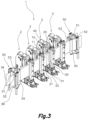
- FIG. 3 shows a perspective view of a third exemplary embodiment of a welding unit 1 for an automatic flexible pouch forming machine according to the present invention.
- This third exemplary embodiment comprises four sets of first lateral elements 10, central elements 20 and second lateral elements 30, with the corresponding first, second, third and fourth pressure applicators 11, 21, 22, 31 and driving means 40. That is to say, this third exemplary embodiment comprises four welding assemblies 2.
- the number of operations or welds performed on the first and second pouch precursors 3A, 3B also increases for a given period of time, as the plurality of welding assemblies 2 allow to perform multiple operations on a simultaneous or substantially simultaneous manner.
- each welding assembly 2 performs a different welding operation, but in other embodiments with a plurality of welding assemblies 2, each welding assembly 2 can perform the same operation, so that a certain operation is performed n times, where n is the number of welding assemblies 2, simultaneously.
- FIG. 3 For clarity purposes, in FIG. 3 the reference numerals of the first lateral element 10, the central element 20, the second lateral element 30, the first, second, third and fourth pressure applicators 11, 21, 22, 31 and the driving means 40 of only one welding assembly 2 have been depicted. However, all welding assemblies 2 of this third exemplary embodiment share the same parts and the above explanation is also applicable to them.
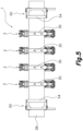
- FIGS. 4 to 6 show a top, a front and a side view of the third exemplary embodiment of a welding unit 1 shown in FIG. 3 .
- this third exemplary embodiment of a welding unit 1 its components or elements are arranged in a linear manner, as in this embodiment the first and second paths for a first and second pouch precursors 3A, 3B are linear.
- said paths for the first and second pouch precursors 3A, 3B may be non-linear, for example, curved, in which case the elements of the welding unit 1 are also arranged in a non-linear manner, adapted to the paths of the first and second pouch precursors 3A, 3B.
- FIGS. 5 and 6 show how the first and second pouch precursors 3A, 3B are surrounded by the welding assemblies 2.
- the first pouch precursor 3A is surrounded by the first pressure applicator 11 of the first lateral element 10, the second pressure applicator 21 of the central element 20, part of the driving means 40 and the lower body of the welding assembly 2.
- the second pouch precursor 3B is surrounded by the third pressure applicator 22 of the central element 20, the fourth pressure applicator 31 of the second lateral element 30, part of the driving means 40 and the lower body of the welding assembly 2.
- a second aspect of the present invention comprises an automatic flexible pouch forming machine comprising a welding unit 1 as previously described.
- the automatic flexible pouch forming machine can comprise a first unwinding unit for unwinding a first band of a flexible heat-sealable film in a first forward movement direction; a first folding unit of the first band configured for folding said band along at least one first folding line parallel to the first forward movement direction, at least two portions of the first band being arranged on opposite sides of said at least one first folding line and the same face of the first band being arranged opposite one another; a second unwinding unit for unwinding a second band of a flexible heat-sealable film in a second forward movement direction; and a second folding unit of the second band configured for folding said band along at least one second folding line parallel to the second forward movement direction, at least two portions of the second band being arranged on opposite sides of said at least one second folding line and the same face of the second band being arranged opposite one another
Landscapes
- Engineering & Computer Science (AREA)
- Mechanical Engineering (AREA)
- Making Paper Articles (AREA)
Claims (15)
- Unité de soudage (1) destinée à une machine automatique de formation de sachet souple comprenant :- des premier et deuxième applicateurs de pression (11, 21) se faisant face, formant ainsi un premier trajet pour un premier précurseur de sachet (3A) constitué d'une bande pliée de film souple thermoscellable,- des moyens de chauffage chauffant au moins l'un desdits premier et deuxième applicateurs de pression (11, 21), et- des moyens d'entraînement (40) pour déplacer au moins l'un desdits premier et deuxième applicateurs de pression (11, 21) entre une position de libération, dans laquelle le premier et deuxième applicateurs de pression (11, 21) sont séparés du premier trajet, et une position de soudage, dans laquelle le premier et deuxième applicateurs de pression (11, 21) pressent et appliquent de la chaleur sur le premier précurseur de sachet (3A) pour former une soudure,caractérisée en ce qu'elle comprend :un premier élément latéral (10) comprenant le premier applicateur de pression (11) ;un élément central (20) comprenant le deuxième applicateur de pression (21) et un troisième applicateur de pression (22) sur des côtés opposés de celui-ci ;un deuxième élément latéral (30) comprenant un quatrième applicateur de pression (31) faisant face au troisième applicateur de pression (22), formant ainsi un deuxième trajet pour un deuxième précurseur de sachet (3B) constitué d'une bande pliée de film souple thermoscellable ;dans laquelle les moyens de chauffage chauffent également au moins l'un desdits troisième et quatrième applicateurs de pression (22, 31) ; etdans laquelle au moins l'un desdits troisième et quatrième applicateurs de pression (22, 31) peuvent se déplacer entre une position de libération, dans laquelle le troisième et quatrième applicateurs de pression (22, 31) sont séparés du deuxième trajet, et une position de soudage, dans laquelle le troisième et quatrième applicateurs de pression (22, 31) pressent et appliquent de la chaleur sur le deuxième précurseur de sachet (3B) pour former une soudure ;et dans laquelle au moins l'un du troisième et quatrième applicateurs de pression (22, 31) est opérationnellement relié auxdits moyens d'entraînement (40), de sorte qu'au moins l'un desdits premier et deuxième applicateurs de pression (11, 21) et au moins l'un desdits troisième et quatrième applicateurs de pression (22, 31) se déplacent simultanément de la position de libération vers la position de soudage, et vice versa.
- Unité de soudage (1), selon la revendication 1, caractérisée en ce que les moyens d'entraînement (40) déplacent simultanément le premier élément latéral (10) et l'élément central (20) par rapport au deuxième élément latéral (30) pour déplacer le premier, deuxième, troisième et quatrième applicateurs de pression (11, 21, 22, 31) de la position de libération vers la position de soudage, et vice versa.
- Unité de soudage (1), selon la revendication 1, caractérisée en ce que les moyens d'entraînement (40) déplacent simultanément le deuxième élément latéral (20) et l'élément central (20) par rapport au premier élément latéral (10) pour déplacer le premier, deuxième, troisième et quatrième applicateurs de pression (11, 21, 22, 31) de la position de libération vers la position de soudage, et vice versa.
- Unité de soudage (1), selon la revendication 1, caractérisée en ce que les moyens d'entraînement déplacent simultanément le premier et deuxième éléments latéraux (10, 30) par rapport à l'élément central (20) pour déplacer le premier, deuxième, troisième et quatrième applicateurs de pression (11, 21, 22, 31) de la position de libération vers la position de soudage, et vice versa.
- Unité de soudage (1), selon l'une quelconque des revendications précédentes, caractérisée en ce que le premier, deuxième, troisième et quatrième applicateurs de pression (11, 21, 22, 31) sont mutuellement alignés.
- Unité de soudage (1), selon l'une quelconque des revendications précédentes, caractérisée en ce qu'elle comprend en outre au moins une unité de guidage (50) pour guider le premier et deuxième précurseurs de sachet (3A, 3B).
- Unité de soudage (1), selon la revendication 6, caractérisée en ce qu'elle comprend au moins une unité de guidage (50) en amont des applicateurs de pression (11, 21, 22, 31) ; et au moins une unité de guidage (50) en aval des applicateurs de pression (11, 21, 22, 31).
- Unité de soudage (1), selon la revendication 6 ou 7, dans laquelle le premier trajet du premier précurseur de sachet (3A) est séparé du deuxième trajet du deuxième précurseur de sachet (3B) par une première distance ; et dans laquelle l'unité de guidage (50) est configurée en outre pour garder ladite première distance et permettre de modifier au moins l'un dudit premier et dudit deuxième trajets de sorte qu'ils soient séparés par une deuxième distance.
- Unité de soudage (1), selon la revendication 8, dans laquelle la deuxième distance est supérieure à la première distance.
- Unité de soudage (1), selon l'une quelconque des revendications 7 à 9, caractérisée en ce que l'unité de guidage (50) comprend un premier rouleau (51) pour être placé en contact avec, et guider, le premier précurseur de sachet (3A) et un deuxième rouleau (52) pour être placé en contact avec, et guider, le deuxième précurseur de sachet (3B), chaque rouleau (51, 52) définissant un axe longitudinal parallèle au précurseur de sachet (3A, 3B) correspondant.
- Unité de soudage (1), selon la revendication 10, caractérisée en ce que l'unité de guidage (50) comprend en outre un troisième rouleau (53) pour être placé en contact avec, et guider, le premier précurseur de sachet (3A), définissant un axe longitudinal parallèle au premier précurseur de sachet (3A), et étant disposé de manière pivotante autour d'un axe de pivot parallèle à l'axe longitudinal du premier rouleau (51) ;
et en ce que l'unité de guidage (50) comprend en outre un quatrième rouleau (54) pour être placé en contact avec, et guider, le deuxième précurseur de sachet (3B), définissant un axe longitudinal parallèle au deuxième précurseur de sachet (3B), et étant disposé de manière pivotante autour d'un axe de pivot parallèle à l'axe longitudinal du deuxième rouleau (52). - Unité de soudage (1), selon l'une quelconque des revendications précédentes, caractérisée en ce qu'elle comprend au moins un deuxième ensemble de premier, deuxième, troisième et quatrième applicateurs de pression (11, 21, 22, 31).
- Machine automatique de formation de sachet souple comprenant une unité de soudage (1) selon l'une quelconque des revendications 1 à 12.
- Machine automatique de formation de sachet souple, selon la revendication 13, caractérisée en ce qu'elle comprend en outre :une première unité de déroulement pour dérouler une première bande d'un film souple thermoscellable dans une première direction de déplacement vers l'avant ;une première unité de pliage de la première bande configurée pour plier ladite bande le long d'au moins une première ligne de pliage parallèle à la première direction de déplacement vers l'avant, au moins deux portions de la première bande étant disposées sur des côtés opposés de ladite au moins une première ligne de pliage et la même face de la première bande étant disposée en face l'une de l'autre ;une deuxième unité de déroulement pour dérouler une deuxième bande d'un film souple thermoscellable dans une deuxième direction de déplacement vers l'avant ; etune deuxième unité de pliage de la deuxième bande configurée pour plier ladite bande le long d'au moins une deuxième ligne de pliage parallèle à la deuxième direction de déplacement vers l'avant, au moins deux portions de la deuxième bande étant disposées sur des côtés opposés de ladite au moins une deuxième ligne de pliage et la même face de la deuxième bande étant disposée en face l'une de l'autre.
- Machine automatique de formation de sachet souple, selon la revendication 14, caractérisée en ce qu'elle comprend en outre au moins une unité de coupe pour séparer des portions constituant des sachets souples à partir de la première et deuxième bandes.
Priority Applications (2)
| Application Number | Priority Date | Filing Date | Title |
|---|---|---|---|
| ES21382850T ES3037057T3 (en) | 2021-09-21 | 2021-09-21 | Welding unit for an automatic flexible pouch forming machine and automatic flexible pouch forming machine comprising the same |
| EP21382850.2A EP4151394B1 (fr) | 2021-09-21 | 2021-09-21 | Unité de soudage destinée à une machine automatique de formation de sachet souple et machine automatique de formation de sachet souple la comprenant |
Applications Claiming Priority (1)
| Application Number | Priority Date | Filing Date | Title |
|---|---|---|---|
| EP21382850.2A EP4151394B1 (fr) | 2021-09-21 | 2021-09-21 | Unité de soudage destinée à une machine automatique de formation de sachet souple et machine automatique de formation de sachet souple la comprenant |
Publications (2)
| Publication Number | Publication Date |
|---|---|
| EP4151394A1 EP4151394A1 (fr) | 2023-03-22 |
| EP4151394B1 true EP4151394B1 (fr) | 2025-06-04 |
Family
ID=77924330
Family Applications (1)
| Application Number | Title | Priority Date | Filing Date |
|---|---|---|---|
| EP21382850.2A Active EP4151394B1 (fr) | 2021-09-21 | 2021-09-21 | Unité de soudage destinée à une machine automatique de formation de sachet souple et machine automatique de formation de sachet souple la comprenant |
Country Status (2)
| Country | Link |
|---|---|
| EP (1) | EP4151394B1 (fr) |
| ES (1) | ES3037057T3 (fr) |
Family Cites Families (2)
| Publication number | Priority date | Publication date | Assignee | Title |
|---|---|---|---|---|
| US6195967B1 (en) * | 1998-11-03 | 2001-03-06 | Klockner Bartelt, Inc. | Packaging machine having continuous and intermittent modes |
| DE102009041411A1 (de) * | 2009-09-16 | 2011-03-24 | Lemo Maschinenbau Gmbh | Verfahren und Vorrichtung zum Längsschweißen von Kunststofffolien |
-
2021
- 2021-09-21 EP EP21382850.2A patent/EP4151394B1/fr active Active
- 2021-09-21 ES ES21382850T patent/ES3037057T3/es active Active
Also Published As
| Publication number | Publication date |
|---|---|
| ES3037057T3 (en) | 2025-09-26 |
| EP4151394A1 (fr) | 2023-03-22 |
Similar Documents
| Publication | Publication Date | Title |
|---|---|---|
| EP3319878B1 (fr) | Machine d'emballage pour un produit unique ou des produits groupés et/ou empilés, dans des paquets de matériau thermoplastique obtenu à partir d'un film déroulé à partir d'un rouleau et procédé de fonctionnement associé | |
| JPH05262335A (ja) | パッケージフィルムに閉鎖手段を整列装着する方法及び装置 | |
| JPH05345355A (ja) | 溶着可能なフイルムから製造された材料のウエブの端部を接着する方法および装置 | |
| MX2014008989A (es) | Unidad de doblado para maquinas de empaque de producto alimenticio vertible. | |
| CN102639399A (zh) | 自动包装机 | |
| EP3980338B1 (fr) | Machine d'emballage pour emballer des rouleaux de papier | |
| WO2022224283A1 (fr) | Machine d'emballage | |
| EP2143555A1 (fr) | Machine pour la fabrication de matériau d'emballage sous forme de coussinets remplis d'air ou de gas. | |
| EP2114772B1 (fr) | Machine et procédé pour emballer des groupes de produits avec un système double étanche à la chaleur | |
| EP4151394A1 (fr) | Unité de soudage destinée à une machine automatique de formation de sachet souple et machine automatique de formation de sachet souple la comprenant | |
| IT202200021408A1 (it) | Apparato di piegatura e macchina di confezionamento avente un apparato di piegatura | |
| JP2011084325A (ja) | 多列自動包装機の包装フィルム搬送調整装置 | |
| JP6698314B2 (ja) | 折り目形成装置、ピロー包装機、包装材、包装方法およびピロー包装体 | |
| EP3392171B1 (fr) | Machine de formation d'emballage flexible pour conditionnement horizontal et procédé de fabrication d'emballages flexibles | |
| JP3929457B2 (ja) | 包装装置 | |
| JP2024063542A (ja) | ヒートシール装置 | |
| JP2019038582A (ja) | 内容物の充填包装方法及び縦型充填包装機 | |
| JP2012131513A (ja) | 包装機 | |
| JP2025171455A (ja) | 脱気装置及びそれを備えた包装機 | |
| IT202300001578A1 (it) | Apparato per formare pacchetti per una macchina di confezionamento e macchina di confezionamento per formare pacchetti riempiti con un prodotto versabile | |
| JP7513253B2 (ja) | 製袋器および包装機 | |
| EP3919261B1 (fr) | Station de soudage longitudinal pour une installation de fabrication d'emballages avec pads | |
| JP6111047B2 (ja) | コーナーシール装置及びそれを用いたピロー包装機 | |
| JP2025158331A (ja) | 製袋器 | |
| JP2022111650A (ja) | 縦シール装置およびその縦シール装置を備えた縦型充填包装設備 |
Legal Events
| Date | Code | Title | Description |
|---|---|---|---|
| PUAI | Public reference made under article 153(3) epc to a published international application that has entered the european phase |
Free format text: ORIGINAL CODE: 0009012 |
|
| STAA | Information on the status of an ep patent application or granted ep patent |
Free format text: STATUS: THE APPLICATION HAS BEEN PUBLISHED |
|
| AK | Designated contracting states |
Kind code of ref document: A1 Designated state(s): AL AT BE BG CH CY CZ DE DK EE ES FI FR GB GR HR HU IE IS IT LI LT LU LV MC MK MT NL NO PL PT RO RS SE SI SK SM TR |
|
| STAA | Information on the status of an ep patent application or granted ep patent |
Free format text: STATUS: REQUEST FOR EXAMINATION WAS MADE |
|
| 17P | Request for examination filed |
Effective date: 20230920 |
|
| RBV | Designated contracting states (corrected) |
Designated state(s): AL AT BE BG CH CY CZ DE DK EE ES FI FR GB GR HR HU IE IS IT LI LT LU LV MC MK MT NL NO PL PT RO RS SE SI SK SM TR |
|
| GRAP | Despatch of communication of intention to grant a patent |
Free format text: ORIGINAL CODE: EPIDOSNIGR1 |
|
| STAA | Information on the status of an ep patent application or granted ep patent |
Free format text: STATUS: GRANT OF PATENT IS INTENDED |
|
| INTG | Intention to grant announced |
Effective date: 20250210 |
|
| GRAS | Grant fee paid |
Free format text: ORIGINAL CODE: EPIDOSNIGR3 |
|
| GRAA | (expected) grant |
Free format text: ORIGINAL CODE: 0009210 |
|
| STAA | Information on the status of an ep patent application or granted ep patent |
Free format text: STATUS: THE PATENT HAS BEEN GRANTED |
|
| AK | Designated contracting states |
Kind code of ref document: B1 Designated state(s): AL AT BE BG CH CY CZ DE DK EE ES FI FR GB GR HR HU IE IS IT LI LT LU LV MC MK MT NL NO PL PT RO RS SE SI SK SM TR |
|
| REG | Reference to a national code |
Ref country code: GB Ref legal event code: FG4D |
|
| REG | Reference to a national code |
Ref country code: CH Ref legal event code: EP |
|
| P01 | Opt-out of the competence of the unified patent court (upc) registered |
Free format text: CASE NUMBER: APP_23673/2025 Effective date: 20250519 |
|
| REG | Reference to a national code |
Ref country code: DE Ref legal event code: R096 Ref document number: 602021031715 Country of ref document: DE |
|
| REG | Reference to a national code |
Ref country code: IE Ref legal event code: FG4D |
|
| REG | Reference to a national code |
Ref country code: ES Ref legal event code: FG2A Ref document number: 3037057 Country of ref document: ES Kind code of ref document: T3 Effective date: 20250926 |
|
| REG | Reference to a national code |
Ref country code: NL Ref legal event code: MP Effective date: 20250604 |
|
| PG25 | Lapsed in a contracting state [announced via postgrant information from national office to epo] |
Ref country code: FI Free format text: LAPSE BECAUSE OF FAILURE TO SUBMIT A TRANSLATION OF THE DESCRIPTION OR TO PAY THE FEE WITHIN THE PRESCRIBED TIME-LIMIT Effective date: 20250604 |
|
| REG | Reference to a national code |
Ref country code: LT Ref legal event code: MG9D |
|
| PG25 | Lapsed in a contracting state [announced via postgrant information from national office to epo] |
Ref country code: GR Free format text: LAPSE BECAUSE OF FAILURE TO SUBMIT A TRANSLATION OF THE DESCRIPTION OR TO PAY THE FEE WITHIN THE PRESCRIBED TIME-LIMIT Effective date: 20250905 Ref country code: NO Free format text: LAPSE BECAUSE OF FAILURE TO SUBMIT A TRANSLATION OF THE DESCRIPTION OR TO PAY THE FEE WITHIN THE PRESCRIBED TIME-LIMIT Effective date: 20250904 |
|
| PG25 | Lapsed in a contracting state [announced via postgrant information from national office to epo] |
Ref country code: PL Free format text: LAPSE BECAUSE OF FAILURE TO SUBMIT A TRANSLATION OF THE DESCRIPTION OR TO PAY THE FEE WITHIN THE PRESCRIBED TIME-LIMIT Effective date: 20250604 |
|
| PGFP | Annual fee paid to national office [announced via postgrant information from national office to epo] |
Ref country code: IT Payment date: 20250904 Year of fee payment: 5 |
|
| PG25 | Lapsed in a contracting state [announced via postgrant information from national office to epo] |
Ref country code: BG Free format text: LAPSE BECAUSE OF FAILURE TO SUBMIT A TRANSLATION OF THE DESCRIPTION OR TO PAY THE FEE WITHIN THE PRESCRIBED TIME-LIMIT Effective date: 20250604 |
|
| PGFP | Annual fee paid to national office [announced via postgrant information from national office to epo] |
Ref country code: GB Payment date: 20250929 Year of fee payment: 5 |
|
| PG25 | Lapsed in a contracting state [announced via postgrant information from national office to epo] |
Ref country code: HR Free format text: LAPSE BECAUSE OF FAILURE TO SUBMIT A TRANSLATION OF THE DESCRIPTION OR TO PAY THE FEE WITHIN THE PRESCRIBED TIME-LIMIT Effective date: 20250604 |
|
| PGFP | Annual fee paid to national office [announced via postgrant information from national office to epo] |
Ref country code: AT Payment date: 20251020 Year of fee payment: 5 |
|
| PG25 | Lapsed in a contracting state [announced via postgrant information from national office to epo] |
Ref country code: RS Free format text: LAPSE BECAUSE OF FAILURE TO SUBMIT A TRANSLATION OF THE DESCRIPTION OR TO PAY THE FEE WITHIN THE PRESCRIBED TIME-LIMIT Effective date: 20250904 |
|
| PG25 | Lapsed in a contracting state [announced via postgrant information from national office to epo] |
Ref country code: LV Free format text: LAPSE BECAUSE OF FAILURE TO SUBMIT A TRANSLATION OF THE DESCRIPTION OR TO PAY THE FEE WITHIN THE PRESCRIBED TIME-LIMIT Effective date: 20250604 |
|
| PG25 | Lapsed in a contracting state [announced via postgrant information from national office to epo] |
Ref country code: NL Free format text: LAPSE BECAUSE OF FAILURE TO SUBMIT A TRANSLATION OF THE DESCRIPTION OR TO PAY THE FEE WITHIN THE PRESCRIBED TIME-LIMIT Effective date: 20250604 |
|
| PG25 | Lapsed in a contracting state [announced via postgrant information from national office to epo] |
Ref country code: PT Free format text: LAPSE BECAUSE OF FAILURE TO SUBMIT A TRANSLATION OF THE DESCRIPTION OR TO PAY THE FEE WITHIN THE PRESCRIBED TIME-LIMIT Effective date: 20251006 |
|
| REG | Reference to a national code |
Ref country code: AT Ref legal event code: MK05 Ref document number: 1799959 Country of ref document: AT Kind code of ref document: T Effective date: 20250604 |
|
| PG25 | Lapsed in a contracting state [announced via postgrant information from national office to epo] |
Ref country code: IS Free format text: LAPSE BECAUSE OF FAILURE TO SUBMIT A TRANSLATION OF THE DESCRIPTION OR TO PAY THE FEE WITHIN THE PRESCRIBED TIME-LIMIT Effective date: 20251004 |
|
| PGFP | Annual fee paid to national office [announced via postgrant information from national office to epo] |
Ref country code: DE Payment date: 20251029 Year of fee payment: 5 |
|
| PG25 | Lapsed in a contracting state [announced via postgrant information from national office to epo] |
Ref country code: AT Free format text: LAPSE BECAUSE OF FAILURE TO SUBMIT A TRANSLATION OF THE DESCRIPTION OR TO PAY THE FEE WITHIN THE PRESCRIBED TIME-LIMIT Effective date: 20250604 Ref country code: SM Free format text: LAPSE BECAUSE OF FAILURE TO SUBMIT A TRANSLATION OF THE DESCRIPTION OR TO PAY THE FEE WITHIN THE PRESCRIBED TIME-LIMIT Effective date: 20250604 |
|
| PG25 | Lapsed in a contracting state [announced via postgrant information from national office to epo] |
Ref country code: CZ Free format text: LAPSE BECAUSE OF FAILURE TO SUBMIT A TRANSLATION OF THE DESCRIPTION OR TO PAY THE FEE WITHIN THE PRESCRIBED TIME-LIMIT Effective date: 20250604 |
|
| PG25 | Lapsed in a contracting state [announced via postgrant information from national office to epo] |
Ref country code: EE Free format text: LAPSE BECAUSE OF FAILURE TO SUBMIT A TRANSLATION OF THE DESCRIPTION OR TO PAY THE FEE WITHIN THE PRESCRIBED TIME-LIMIT Effective date: 20250604 |
|
| PG25 | Lapsed in a contracting state [announced via postgrant information from national office to epo] |
Ref country code: SK Free format text: LAPSE BECAUSE OF FAILURE TO SUBMIT A TRANSLATION OF THE DESCRIPTION OR TO PAY THE FEE WITHIN THE PRESCRIBED TIME-LIMIT Effective date: 20250604 |
|
| PGFP | Annual fee paid to national office [announced via postgrant information from national office to epo] |
Ref country code: ES Payment date: 20251021 Year of fee payment: 5 |
|
| PG25 | Lapsed in a contracting state [announced via postgrant information from national office to epo] |
Ref country code: RO Free format text: LAPSE BECAUSE OF FAILURE TO SUBMIT A TRANSLATION OF THE DESCRIPTION OR TO PAY THE FEE WITHIN THE PRESCRIBED TIME-LIMIT Effective date: 20250604 |
|
| REG | Reference to a national code |
Ref country code: DE Ref legal event code: R097 Ref document number: 602021031715 Country of ref document: DE |
|
| PLBE | No opposition filed within time limit |
Free format text: ORIGINAL CODE: 0009261 |
|
| STAA | Information on the status of an ep patent application or granted ep patent |
Free format text: STATUS: NO OPPOSITION FILED WITHIN TIME LIMIT |
|
| PG25 | Lapsed in a contracting state [announced via postgrant information from national office to epo] |
Ref country code: DK Free format text: LAPSE BECAUSE OF FAILURE TO SUBMIT A TRANSLATION OF THE DESCRIPTION OR TO PAY THE FEE WITHIN THE PRESCRIBED TIME-LIMIT Effective date: 20250604 |
|
| REG | Reference to a national code |
Ref country code: CH Ref legal event code: L10 Free format text: ST27 STATUS EVENT CODE: U-0-0-L10-L00 (AS PROVIDED BY THE NATIONAL OFFICE) Effective date: 20260416 |
|
| REG | Reference to a national code |
Ref country code: CH Ref legal event code: H13 Free format text: ST27 STATUS EVENT CODE: U-0-0-H10-H13 (AS PROVIDED BY THE NATIONAL OFFICE) Effective date: 20260425 |
|
| 26N | No opposition filed |
Effective date: 20260305 |