EP4150425B1 - Mobiler signalgenerator für ein robotisches arbeitswerkzeug - Google Patents
Mobiler signalgenerator für ein robotisches arbeitswerkzeug Download PDFInfo
- Publication number
- EP4150425B1 EP4150425B1 EP21803572.3A EP21803572A EP4150425B1 EP 4150425 B1 EP4150425 B1 EP 4150425B1 EP 21803572 A EP21803572 A EP 21803572A EP 4150425 B1 EP4150425 B1 EP 4150425B1
- Authority
- EP
- European Patent Office
- Prior art keywords
- signal generator
- control signal
- supplemental
- mobile
- mobile signal
- Prior art date
- Legal status (The legal status is an assumption and is not a legal conclusion. Google has not performed a legal analysis and makes no representation as to the accuracy of the status listed.)
- Active
Links
Images


Classifications
-
- G—PHYSICS
- G05—CONTROLLING; REGULATING
- G05D—SYSTEMS FOR CONTROLLING OR REGULATING NON-ELECTRIC VARIABLES
- G05D1/00—Control of position, course, altitude or attitude of land, water, air or space vehicles, e.g. using automatic pilots
- G05D1/02—Control of position or course in two dimensions
- G05D1/021—Control of position or course in two dimensions specially adapted to land vehicles
- G05D1/0259—Control of position or course in two dimensions specially adapted to land vehicles using magnetic or electromagnetic means
- G05D1/0265—Control of position or course in two dimensions specially adapted to land vehicles using magnetic or electromagnetic means using buried wires
-
- G—PHYSICS
- G05—CONTROLLING; REGULATING
- G05D—SYSTEMS FOR CONTROLLING OR REGULATING NON-ELECTRIC VARIABLES
- G05D1/00—Control of position, course, altitude or attitude of land, water, air or space vehicles, e.g. using automatic pilots
- G05D1/40—Control within particular dimensions
- G05D1/43—Control of position or course in two dimensions [2D]
-
- G—PHYSICS
- G05—CONTROLLING; REGULATING
- G05D—SYSTEMS FOR CONTROLLING OR REGULATING NON-ELECTRIC VARIABLES
- G05D1/00—Control of position, course, altitude or attitude of land, water, air or space vehicles, e.g. using automatic pilots
- G05D1/02—Control of position or course in two dimensions
- G05D1/021—Control of position or course in two dimensions specially adapted to land vehicles
- G05D1/0259—Control of position or course in two dimensions specially adapted to land vehicles using magnetic or electromagnetic means
-
- A—HUMAN NECESSITIES
- A01—AGRICULTURE; FORESTRY; ANIMAL HUSBANDRY; HUNTING; TRAPPING; FISHING
- A01D—HARVESTING; MOWING
- A01D34/00—Mowers; Mowing apparatus of harvesters
- A01D34/006—Control or measuring arrangements
- A01D34/008—Control or measuring arrangements for automated or remotely controlled operation
-
- A—HUMAN NECESSITIES
- A01—AGRICULTURE; FORESTRY; ANIMAL HUSBANDRY; HUNTING; TRAPPING; FISHING
- A01D—HARVESTING; MOWING
- A01D2101/00—Lawn-mowers
-
- G—PHYSICS
- G05—CONTROLLING; REGULATING
- G05D—SYSTEMS FOR CONTROLLING OR REGULATING NON-ELECTRIC VARIABLES
- G05D2111/00—Details of signals used for control of position, course, altitude or attitude of land, water, air or space vehicles
- G05D2111/30—Radio signals
- G05D2111/36—Radio signals generated or reflected by cables or wires carrying current, e.g. boundary wires or leaky feeder cables
Definitions
- This application relates to robotic working tools and in particular to a system and a method for providing a mobile signal generator for a robotic working tool, such as a lawnmower.
- Automated or robotic power tools such as robotic lawnmowers are becoming increasingly more popular.
- a work area such as a garden
- the work area is enclosed by a boundary wire with the purpose of keeping the robotic lawnmower inside the work area.
- An electric control signal may be transmitted through the boundary wire thereby generating an (electro-) magnetic field emanating from the boundary wire.
- the robotic working tool is typically arranged with one or more (electro-) magnetic sensors adapted to sense the control signal.
- the patent application published as US2005230166A1 discloses a method and an electronic search system for operating an automatic device, preferably an automatic lawnmower.
- the system comprises at least one first electrical cable connected to at least one first signal generator and at least one sensing system arranged on said device.
- Said sensing system detects at least one magnetic field being transmitted via said cable and propagating through the air, the sensing system transmitting a processed signal to at least one driving means which contributes to the movements of said device in relation to a surface.
- Said search system comprises means by which the first signal generator of the present invention transmits a current through said first cable, said current during a part of time being is in a state of rest where it is substantially constant, said state periodically being interrupted by at least one first characteristic current pulse.
- the mobile signal generator comprises a signal generator, arranged to generate the supplemental control signal, and a battery for providing power to the signal generator.
- the mobile signal generator comprises a controller module configured to establish the supplemental control signal.
- mobile signal generator comprises a communication interface, wherein the controller module is configured to establish the supplemental control signal by receiving information regarding the supplemental control signal through the communication interface from a charging station and/or a user.
- the mobile signal generator further comprises a magnetic sensor arranged to sense the magnetic field generated by a control signal, wherein the controller module is configured to establish the supplemental control signal by receiving information regarding the control signal through the magnetic sensor and establish the supplemental control signal to be the same as the control signal.
- the mobile signal generator is arranged outside the supplemental work area.
- the robotic working tool is a robotic lawnmower.
- the robotic lawnmower 100 comprises charging skids 156 for contacting contact plates (not shown in figure 1 , but referenced 213 in figure 2 ) when docking into a charging station (not shown in figure 1 , but referenced 210 in figure 2 ) for receiving a charging current through, and possibly also for transferring information by means of electrical communication between the charging station and the robotic lawnmower 100.
- a charging station not shown in figure 1 , but referenced 210 in figure 2
- Other means of establishing a charging contact are possible and are incorporated herein.
- FIG. 1B shows a schematic overview of the robotic working tool 100, also exemplified here by a robotic lawnmower 100.
- the robotic lawnmower 100 is of a mono-chassis type, having a main body part 140.
- the main body part 140 substantially houses all components of the robotic lawnmower 100.
- the robotic lawnmower 100 has a plurality of wheels 130.
- the robotic lawnmower 100 has four wheels 130, two front wheels and two rear wheels. At least some of the wheels 130 are drivably connected to at least one electric motor 150. It should be noted that even if the description herein is focused on electric motors, combustion engines may alternatively be used, possibly in combination with an electric motor.
- the robotic lawnmower 100 also comprises a grass cutting device 160, such as a rotating blade 160 driven by a cutter motor 165.
- the grass cutting device being an example of a work tool 160 for a robotic working tool 100.
- the robotic lawnmower 100 also has (at least) one battery 155 for providing power to the motor(s) 150 and/or the cutter motor 165.
- the battery is arranged to be charged through a current received through charging skids 156 - or other suitable charging connectors.
- the robotic lawnmower 100 also comprises a controller 110 and a computer readable storage medium or memory 120.
- the controller 110 may be implemented using instructions that enable hardware functionality, for example, by using executable computer program instructions in a general-purpose or special-purpose processor that may be stored on the memory 120 to be executed by such a processor.
- the controller 110 is configured to read instructions from the memory 120 and execute these instructions to control the operation of the robotic lawnmower 100 including, but not being limited to, the propulsion of the robotic lawnmower.
- the controller 110 may be implemented using any suitable, available processor or Programmable Logic Circuit (PLC).
- PLC Programmable Logic Circuit
- the memory 120 may be implemented using any commonly known technology for computer-readable memories such as ROM, RAM, SRAM, DRAM, FLASH, DDR, SDRAM or some other memory technology.
- the robotic lawnmower 100 may further be arranged with a wireless communication interface 115 for communicating with other devices, such as a server, a personal computer or smartphone, the charging station, and/or other robotic working tools.
- wireless communication devices such as Bluetooth ® , WiFi ® (IEEE802.11b), Global System Mobile (GSM) and LTE (Long Term Evolution), to name a few.
- the robotic lawnmower 100 is further configured to have at least one magnetic field sensor 170 arranged to detect the magnetic field (not shown) and for detecting the boundary wire and/or for receiving (and possibly also sending) information to/from a signal generator (will be discussed with reference to figure 2 ).
- the sensors 170 may be connected to the controller 110, possibly via filters and an amplifier, and the controller 110 may be configured to process and evaluate any signals received from the sensors 170.
- the sensor signals are caused by the magnetic field being generated by the control signal being transmitted through the boundary wire. This enables the controller 110 to determine whether the robotic lawnmower 100 is close to or crossing the boundary wire, or inside or outside an area enclosed by the boundary wire.
- the robotic lawnmower 100 may further comprise at least one navigation sensor 175.
- the navigation sensor 175 comprises one or more sensors for deduced navigation. Examples of sensors for deduced reckoning are odometers, accelerometers, gyroscopes, and compasses to mention a few examples.
- the navigation sensor 175 comprises a beacon navigation sensor and/or a satellite navigation sensor 190.
- the beacon navigation sensor may be a Radio Frequency receiver, such as an Ultra Wide Band (UWB) receiver or sensor, configured to receive signals from a Radio Frequency beacon, such as a UWB beacon.
- the beacon navigation sensor may be an optical receiver configured to receive signals from an optical beacon.
- the satellite navigation sensor may be a GPS (Global Positioning System) device or other Global Navigation Satellite System (GNSS) device.
- GPS Global Positioning System
- GNSS Global Navigation Satellite System
- FIG 2 shows a schematic view of a robotic working tool system 200.
- the schematic view is not to scale.
- the robotic working tool system 200 comprises a robotic working tool 100.
- the robotic working tool is exemplified by a robotic lawnmower, whereby the robotic working tool system may be a robotic lawnmower system or a system comprising a combinations of robotic working tools, one being a robotic lawnmower, but the teachings herein may also be applied to other robotic working tools adapted to operate within a work area.
- the robotic working tool system 200 also comprises charging station 210 which is arranged with a signal generator 215 and a boundary wire 220.
- the signal generator is arranged to generate a control signal 225 to be transmitted through the boundary wire 220.
- the signal generator is arranged with a controller and memory module 216.
- the controller and memory module 216 operates and functions in a similar manner as the controller 110 and memory 120 of the robotic working tool 100.
- the controller and memory module 216 may also be the controller and memory module of the charging station, hereafter simply referred to as the controller 216.
- controller and memory module 216 may also comprise or be connected to a communication interface (not shown explicitly but considered to be part of the controller and memory module).
- the communication interface is enabled for communicating with other devices, such as a server, a personal computer or smartphone, a robotic working tool 100, another signal generator and/or another charging station using a wireless communication standard. Examples of such wireless communication standards are Bluetooth ® , WiFi ® (IEEE802.11b), Global System Mobile (GSM) and LTE (Long Term Evolution), to name a few.
- the boundary wire 220 is arranged to enclose a work area 205, in which the robotic lawnmower 100 is supposed to serve.
- the control signal 225 transmitted through the boundary wire 220 causes a magnetic field (not shown) to be emitted.
- the control signal 225 is a sinusoid periodic current signal.
- the control signal 225 is a pulsed current signal comprising a periodic train of pulses.
- the control signal 225 is a coded signal, such as a CDMA signal.
- a magnetic field is generated.
- the magnetic field may be detected using field sensors, such as Hall sensors.
- a sensor - in its simplest form - is a coil surrounding a conductive core, such as a ferrite core.
- the amplitude of the sensed magnetic field is proportional to the derivate of the control signal.
- a large variation (fast and/or of great magnitude) results in a high amplitude for the sensed magnetic field.
- the variations are sensed and compared to a reference signal or pattern of variations in order to identify and thereby reliably sense the control signal.
- the work area 205 is in this application exemplified as a garden, but can also be other work areas as would be understood.
- the garden contains a number of obstacles (O), exemplified herein by a number (3) of trees (T) and a house structure (H).
- the trees are marked both with respect to their trunks (filled lines) and the extension of their foliage (dashed lines).
- the boundary wire 220 has been laid so that so-called islands are formed around the trees' trunks and the house (H). This requires that more boundary wire is used, than if the work area was without such obstacles. It should be noted that any distances between wires are greatly exaggerated in this application in order to make the distances visible in the drawings.
- the charging station 210 is fastened into the ground by one or several pegs 214 in order to keep the charging station stable as the robotic lawnmower 100 drives up on it to be charged, and off it once charged and ready to operate.
- the charging station 210 is also, for the same reason, arranged with a bottom plate 217 that is designed to be larger than the corresponding robotic lawnmower 100. As a skilled person would understand, the larger the bottom plate 217, the more stable the installation. The bottom plate 217 is therefore usually rather bulky.
- the charging station 210 also comprises a charging unit 212, connected to two charging plates 213, for delivering a charging current to the robotic lawnmower 100 upon docking.
- the charging unit 212 is connected to a power supply 211. As the charging requires significant current, the power supply 211 is external. Usually, the charging station is simply connected to a wall outlet in a house or similar structure.
- the charging station is also, usually, connected to one or more guide wires 221.
- Guide wires 221 may be used to enable the robotic lawnmower 10 to find its way to a specific area, such as into (and/or out of) areas that are difficult to reach.
- Guide wires 221 may alternatively or additionally be used to enable the robotic lawnmower 10 to find its way to the charging station 210.
- Guide wires 221 may alternatively or additionally be used to divide a work area 205 into two separate work areas.
- FIG. 2 there are two guide wires, a first guide wire 221-1 arranged to lead the robotic lawnmower 100 in to the area behind the trees T, and a second guide wire 221-2 arranged to lead the robotic lawnmower 100 to the charging station 210.
- the second guide wire 221-2 may also or alternatively be used to divide the work area 205 into two halves, one to the left of the second guide wire 221-2 and one to the right of the second guide wire 221-2.
- guide wires 221 to demarcate work areas has been around for several years, and a skilled person would understand how such uses may be implemented without further details.
- the inventors have realized and identified several problems associated with using guide wires 221 to demarcate a work area 205.
- Another problem lies in that as the guide wire 221-2 need be connected to the charging station 210, it is difficult to install the guide wire for a sub-area far away from the charging station 210. Especially if there are obstacles that should not be disturbed in the way between the wanted subarea and the charging station 210.
- the obvious solution to setting up such a remote o external sub area is to simply move the charging station and set up a new boundary wire.
- the charging station 210 is pegged down, needs to be connected to a power supply 211 and as all guide wires 221 as well as the original boundary wire 220 need be disconnected, this is not such a simple task as technically skilled users may believe, especially not for most end-users who may lack in practical or technical skills as their expertise may lay elsewhere in non-technical fields.
- persons skilled in areas such as finance, business methods, mathematics, computer software, psychology, and aesthetics often lack technical knowledge.
- the charging station 210 may also be heavy or otherwise cumbersome to carry or transport making it unsuitable to be moved.
- the inventors are therefore - after insightful and inventive reasoning - proposing the simple and elegant solution of providing a mobile signal generator that can be used at any location for setting up a boundary to demark a sub area, remotely or internally to an existing work area 205.
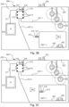
- Figures 3A , 3B and 3C each shows an example embodiment of a robotic working tool system 300, herein exemplified by a robotic lawnmower system, according to an embodiment of the teachings herein.
- the sub area or supplemental 305 is external to the existing work area 205.
- the sub area or supplemental 305 is internal to the existing work area 205, where the robotic lawnmower is inside the supplemental area in figure 3B and outside of it in figure 3C .
- the mobile signal generator 315 need not be arranged inside a work area as it need not be accessed by the robotic lawnmower 100.
- Figures 3A and 3B shows a situation where the mobile signal generator 315 is arranged outside the supplemental work area 305 and figure 3C shows a situation where the mobile signal generator 315 is arranged inside the supplemental work area 305.
- An external supplemental work area 305 may be used for temporarily setting up a work area externally, such as when an area needs to be worked on or such as when lending ones robotic lawnmower to a friend or neighbour.
- An external supplemental work area 305 may also or alternatively be used for a secondary home, such as a summer cabin. This allows for an easy installation and for theft protection as the mobile signal generator 315 may be easily (as will be discussed below) transported to and from the cabin along with the robotic lawnmower 100.
- the mobile signal generator 315 is arranged to receive an indication of the wire length through the communication interface 413.
- the mobile signal generator 315 may be arranged to receive the indication of the wire length through the user interface 417.
- a user may thus, for example, input the length of the boundary wire being used either through the user interface 417 or through a separate device such as a smart phone.
- the mobile signal generator 315 is arranged to receive an indication of the wire length by measuring the length of the wire.
- the length can be measured or approximated by measuring the resistance in the wire. Assuming a specific thickness and/or resistance per unit of length, the resistance will be proportional to the length and a measurement of the resistance will therefore give an indication of the length of the wire. The measurement may be done at any point where a known voltage is applied to the wire, by measuring the resulting current.
- the mobile signal generator is configured to determine whether the supplemental area is set up as a stay-in-area or as a stay-out-area.
- the mobile signal generator may adapt its operation based on whether the supplemental area is set up as a stay-in-area or as a stay-out-area.
- the operation may be adapted as regards what action is to be taken if the control signal is lost.
- the mobile signal generator is arranged to signal or present the use of the supplemental area to a user through the communication interface and/or through the user interface.
- the mobile signal generator is configured to determine whether the supplemental area is set up as a stay-in-area or as a stay-out-area by determining the position of a switch (as discussed above)
- the mobile signal generator is configured to determine whether the supplemental area is set up as a stay-in-area or as a stay-out-area by sensing the resulting magnetic field being emitted by the transmitted control signal.
- the mobile signal generator is configured to determine whether the control signal from the main system (i.e the control signal 225) is detectable. If the signal is not detectable, the mobile signal generator may be arranged to interrupt all operations. This is also useful for preventing theft of the robotic lawnmower or the mobile signal generator, as it will only be able to operate in the vicinity of the main or original system.
- the mobile signal generator is arranged to determine 'the main control signal 225, to compare it to a storage of known control signals and only operate if a match is found. This enables the mobile signal generator to only operate with preapproved systems, which enables for an increased safety of use as only trusted systems may be used with the mobile signal generator.
- a robotic lawnmower 100 is configured to stop operating as a control signal is lost. This is in order to prevent the robotic lawnmower 100 from escaping the work area in case of a power failure of the signal generator.
- the robotic lawnmower 100 will still sense the control signal 225 even after the supplemental control signal 325 dies or is otherwise lost. This will inevitably lead to the robotic lawnmower 100 escaping the supplemental area 305.
- the inventors have, however, realized a simple and elegant solution to this. By configuring the robotic lawnmower 100 to not only stop operation if a signal is lost, but also stop operation if there is a sudden drop in sensed signal strength, the robotic lawnmower 100 is enabled to detect when the supplemental control signal is lost.
- the mobile signal generator 315 may be configured to also sense the overall control signal and to sense a drastic or sudden change in signal strength, and thereby determine that the main control signal has been lost and in response thereto stop operation of the robotic lawnmower 100.
- the operation may be stopped by communicating to the robotic lawnmower 100 to stop.
- the operation maybe stopped by simply discontinuing the supplemental control signal which effectively will cause the robotic lawnmower 100 to stop as all control signals are lost.
- the sudden drop or change is characterized by a change in signal strength of 30 %, 40 %, 50 % or a higher percentage of the sensed signal strength.
- the mobile signal generator 315 (and/or the robotic lawnmower) may thus 530 sense a change in the signal and stop operation accordingly.
- the mobile signal generator 315 is configured to detect that the battery level has reached a critical (low) level and then signal the robotic lawnmower 100 to stop operating. This ensures that the robotic lawnmower 100 stop inside the supplemental work area 305 even if the mobile signal generator 315 runs out of power.
- the robotic lawnmower 100 is configured to receive such signalling from the mobile signal generator and act accordingly, i.e. to stop operating.
- the mobile signal generator 315 may be configured to signal the robotic lawnmower 100 regarding other commands as well.
- the mobile signal generator 315 is configured to signal the robotic lawnmower 100 through the communications interface 413. In one embodiment, the mobile signal generator 315 is configured to signal the robotic lawnmower 100 through transmitting a coded message through the boundary wire by adapting the supplemental control signal 325 accordingly. The robotic lawnmower 100 may thus sense the coded message as part of sensing the control signal and receive any command, such as a stop operating command.
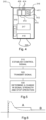
- Figure 6 shows a schematic view of sensed signal strength for two cases of a sensed signal strength dropping.
- the first case (dashed line) is when the robotic lawnmower 100 is close to the (boundary) wire emitting the (control) signal being sensed.
- This peak is however in most cases very short and is easily distinguishable from the other case (full line) where the signal strength suddenly drops from one steady level to a lower, but also steady, level (A to B).
- the robotic lawnmower 100 may determine that a first signal level has been maintained (or at least that the sensed signal has been sensed above the first level) for a time period exceeding a threshold time followed by that a second signal level is maintained for a time period exceeding a second threshold, possibly the same, it may be concluded that the supplemental control signal has been dropped, and the robotic lawnmower should stop operation. IN the case that the determination is wrong, which is however, unlikely as the mobile signal generator - being battery operated - runs a much higher risk of dropping the signal, no safety standards are violated as the robotic lawnmower 100 is still within the overall work area 205.
Landscapes
- Engineering & Computer Science (AREA)
- Physics & Mathematics (AREA)
- Aviation & Aerospace Engineering (AREA)
- Radar, Positioning & Navigation (AREA)
- Remote Sensing (AREA)
- General Physics & Mathematics (AREA)
- Automation & Control Theory (AREA)
- Electromagnetism (AREA)
- Life Sciences & Earth Sciences (AREA)
- Environmental Sciences (AREA)
- Control Of Position, Course, Altitude, Or Attitude Of Moving Bodies (AREA)
- Manipulator (AREA)
Claims (11)
- Mobilsignalgenerator (315), der angeordnet ist, um ein zusätzliches Steuersignal (325) über einen zusätzlichen Draht (320) bereitzustellen, um einen zusätzlichen Arbeitsbereich (320) für ein Roboterarbeitswerkzeug (100) einzurichten, wobei der Mobilsignalgenerator (315) ohne eine Ladeeinheit für das Roboterarbeitswerkzeug (100) angeordnet ist, wobei der Mobilsignalgenerator (315) ein Steuermodul (316) umfasst, das konfiguriert ist, um das zusätzliche Steuersignal (325) einzurichten, und wobei der Mobilsignalgenerator (315)
dadurch gekennzeichnet ist, dass er ferner einen Magnetsensor (416) umfasst, der angeordnet ist, um das Magnetfeld zu erfassen, das durch ein Steuersignal (225) erzeugt wird, wobei das Steuermodul (316) konfiguriert ist, um das zusätzliche Steuersignal (325) durch ein Empfangen von Informationen bezüglich des Steuersignals (225) über den Magnetsensor (416) einzurichten und das zusätzliche Steuersignal (325) als dasselbe wie das Steuersignal (225) einzurichten. - Mobilsignalgenerator (315) nach Anspruch 1, wobei der Mobilsignalgenerator (315) einen Signalgenerator (415), der angeordnet ist, um das zusätzliche Steuersignal (325) zu erzeugen, und eine Batterie (317) zum Versorgen des Signalgenerators (415) mit Leistung umfasst.
- Mobilsignalgenerator (315) nach Anspruch 1 oder 2, ferner umfassend eine Kommunikationsschnittstelle (413), wobei das Steuermodul (316) konfiguriert ist, um das zusätzliche Steuersignal (325) durch das Empfangen von Informationen bezüglich des zusätzlichen Steuersignals (225) über die Kommunikationsschnittstelle (413) von einer Ladestation (210) und/oder einem Benutzer einzurichten.
- Mobilsignalgenerator (315) nach einem der vorstehenden Ansprüche, wobei der Mobilsignalgenerator (315) angeordnet ist, um einen drastischen Abfall in einer erfassten Signalstärke zu erfassen und als Reaktion darauf den Betrieb zu stoppen.
- Mobilsignalgenerator (315) nach einem der vorstehenden Ansprüche, wobei der Mobilsignalgenerator (315) angeordnet ist, um zu bestimmen, dass ein kritischer Batteriestand erreicht wurde und als Reaktion darauf einen Stoppbefehl an das Roboterarbeitswerkzeug (100) zu signalisieren.
- Mobilsignalgenerator (315) nach einem der vorstehenden Ansprüche, wobei der Mobilsignalgenerator (315) angeordnet ist, um die Stärke des zusätzlichen Steuersignals (325) basierend auf einer Länge des zusätzlichen Begrenzungsdrahts (320) anzupassen.
- Mobilsignalgenerator (315) nach einem der vorstehenden Ansprüche, wobei der Mobilsignalgenerator (315) zwei Anschlüsse (414) zum Verbinden eines einzelnen zusätzlichen Begrenzungsdrahts (320) umfasst.
- Mobilsignalgenerator (315) nach einem der vorstehenden Ansprüche, wobei der Mobilsignalgenerator (315), wenn in Betrieb, außerhalb des zusätzlichen Arbeitsbereichs (305) angeordnet ist.
- Mobilsignalgenerator (315) nach einem der vorstehenden Ansprüche, wobei der Mobilsignalgenerator (315) angeordnet ist, um in einem Roboterarbeitswerkzeugsystem (300) verwendet zu werden, umfassend einen Signalgenerator (215), der angeordnet ist, um ein Steuersignal (225) über einen Begrenzungsdraht (220) zu erzeugen und zu übertragen, das Roboterarbeitswerkzeug (100) und eine Ladestation (210) zum Aufladen des Roboterarbeitswerkzeugs (100).
- Mobilsignalgenerator (315) nach einem der vorstehenden Ansprüche, wobei das Roboterarbeitswerkzeug (100) ein Roboter-Rasenmäher (100) ist.
- Verfahren zur Verwendung in einem Mobilsignalgenerator (315), der angeordnet ist, um ein zusätzliches Steuersignal (325) über einen zusätzlichen Draht (320) bereitzustellen, zum Einrichten eines zusätzlichen Arbeitsbereichs (320) für ein Roboterarbeitswerkzeug (100), wobei der Mobilsignalgenerator (315) ohne eine Ladeeinheit für das Roboterarbeitswerkzeug (100) angeordnet ist, das Verfahren umfassend
Einrichten (510) des zusätzlichen Steuersignals (325) und Übertragen (520) des zusätzlichen Steuersignals (325), wobei der Mobilsignalgenerator (315) ein Steuermodul (316) umfasst, das konfiguriert ist, um das zusätzliche Steuersignal (325) einzurichten, und wobei das Verfahren dadurch gekennzeichnet ist, dass der Mobilsignalgenerator (315) ferner einen Magnetsensor (416) umfasst, der angeordnet ist, um das Magnetfeld zu erfassen, das durch ein Steuersignal (225) erzeugt wird, und wobei das Verfahren das Steuermodul (316) umfasst, das das zusätzliche Steuersignal (325) durch das Empfangen von Informationen bezüglich des Steuersignals (225) über den Magnetsensor (416) einrichtet und das zusätzliche Steuersignal (325) als dasselbe wie das Steuersignal (225) einrichtet.
Applications Claiming Priority (2)
| Application Number | Priority Date | Filing Date | Title |
|---|---|---|---|
| SE2050566A SE544111C2 (en) | 2020-05-14 | 2020-05-14 | Mobile signal generator for a robotic working tool |
| PCT/SE2021/050417 WO2021230791A1 (en) | 2020-05-14 | 2021-05-05 | Mobile signal generator for a robotic working tool |
Publications (3)
| Publication Number | Publication Date |
|---|---|
| EP4150425A1 EP4150425A1 (de) | 2023-03-22 |
| EP4150425A4 EP4150425A4 (de) | 2024-03-20 |
| EP4150425B1 true EP4150425B1 (de) | 2025-03-19 |
Family
ID=78524791
Family Applications (1)
| Application Number | Title | Priority Date | Filing Date |
|---|---|---|---|
| EP21803572.3A Active EP4150425B1 (de) | 2020-05-14 | 2021-05-05 | Mobiler signalgenerator für ein robotisches arbeitswerkzeug |
Country Status (4)
| Country | Link |
|---|---|
| US (1) | US20230341868A1 (de) |
| EP (1) | EP4150425B1 (de) |
| SE (1) | SE544111C2 (de) |
| WO (1) | WO2021230791A1 (de) |
Families Citing this family (9)
| Publication number | Priority date | Publication date | Assignee | Title |
|---|---|---|---|---|
| US12296694B2 (en) | 2021-03-10 | 2025-05-13 | Techtronic Cordless Gp | Lawnmowers |
| DE202021104167U1 (de) | 2021-08-04 | 2021-08-18 | Einhell Germany Ag | Tragbare und/oder mobile Signalerzeugungsvorrichtung |
| US12443180B2 (en) | 2021-11-10 | 2025-10-14 | Techtronic Cordless Gp | Robotic lawn mowers |
| AU2023200381A1 (en) | 2022-01-31 | 2023-08-17 | Techtronic Cordless Gp | Robotic garden tool |
| EP4270138A1 (de) | 2022-04-28 | 2023-11-01 | Techtronic Cordless GP | Erzeugung einer virtuellen grenze für ein robotisches gartenwerkzeug |
| US12472611B2 (en) | 2022-05-31 | 2025-11-18 | Techtronic Cordless Gp | Peg driver |
| AU2023204696A1 (en) | 2022-07-19 | 2024-02-08 | Techtronic Cordless Gp | Display for controlling robotic tool |
| AU2023206123A1 (en) | 2022-07-29 | 2024-02-15 | Techtronic Cordless Gp | Generation of a cryptography key for a robotic garden tool |
| US12521886B2 (en) * | 2022-11-23 | 2026-01-13 | Intrinsic Innovation Llc | Streaming input buffer for real-time robotic control |
Family Cites Families (8)
| Publication number | Priority date | Publication date | Assignee | Title |
|---|---|---|---|---|
| SE511254C2 (sv) * | 1998-01-08 | 1999-09-06 | Electrolux Ab | Elektroniskt söksystem för arbetsredskap |
| SE0201739D0 (sv) * | 2002-06-07 | 2002-06-07 | Electrolux Ab | Elektroniskt avgränsningssystem |
| JP6089712B2 (ja) * | 2013-01-16 | 2017-03-08 | 株式会社デンソー | 車両制御システム |
| US9072219B2 (en) * | 2013-06-20 | 2015-07-07 | Deere & Company | Robotic mower navigation system |
| US10078322B2 (en) * | 2016-01-08 | 2018-09-18 | Newfrey Llc | Power tool system having in-station verification utilizing radio frequency signal strength |
| SE541842C2 (en) * | 2017-03-28 | 2019-12-27 | Husqvarna Ab | Improved perimeter marking for a robotic working tool |
| SE541784C2 (en) * | 2017-04-25 | 2019-12-17 | Husqvarna Ab | Robotic lawnmower system and method with adaptive signal transmission |
| GB2577146B (en) * | 2018-08-31 | 2023-01-11 | Mtd Products Inc | Zone mobility system and method for an autonomous device, adaptable power optimization system and method for an autonomous device |
-
2020
- 2020-05-14 SE SE2050566A patent/SE544111C2/en unknown
-
2021
- 2021-05-05 WO PCT/SE2021/050417 patent/WO2021230791A1/en not_active Ceased
- 2021-05-05 EP EP21803572.3A patent/EP4150425B1/de active Active
- 2021-05-05 US US17/924,735 patent/US20230341868A1/en not_active Abandoned
Also Published As
| Publication number | Publication date |
|---|---|
| WO2021230791A1 (en) | 2021-11-18 |
| SE544111C2 (en) | 2021-12-28 |
| EP4150425A4 (de) | 2024-03-20 |
| US20230341868A1 (en) | 2023-10-26 |
| SE2050566A1 (en) | 2021-11-15 |
| EP4150425A1 (de) | 2023-03-22 |
Similar Documents
| Publication | Publication Date | Title |
|---|---|---|
| EP4150425B1 (de) | Mobiler signalgenerator für ein robotisches arbeitswerkzeug | |
| US8930024B2 (en) | Robotic lawnmower and charging and control systems therefor | |
| EP3236734B1 (de) | Verbesserter betrieb eines robotischen arbeitswerkzeugs durch anpassung des betriebs an die wetterbedingungen | |
| EP3724738B1 (de) | Robotisches arbeitswerkzeug und verfahren zur abtastung einer arbeitsbereichsabgrenzung | |
| EP3084543B1 (de) | Hinderniserkennung für eine robotische mähmachine | |
| EP3610344B1 (de) | Mobile vorrichtung für aussenstromversorgung | |
| EP3776107B1 (de) | Verbesserte betriebsfähigkeit für ein robotisches arbeitswerkzeug | |
| US11310957B2 (en) | Reduction of wheel tracks for robotic lawnmower | |
| EP2547191B1 (de) | Verfahren und system zur lenkung eines robotischen garteninstruments in eine vorgegebene position | |
| EP3712738A1 (de) | Selbstbewegende vorrichtung und betriebssystem, erkennungsverfahren und betriebsverfahren dafür | |
| WO2018108179A1 (zh) | 自移动设备及其定位故障报警方法和自动工作系统 | |
| CN105896673A (zh) | 一种充电起落架、无人机、充电平台及无人机续航充电系统 | |
| CN106300578A (zh) | 自主移动设备及其无线充电系统 | |
| WO2020256619A1 (en) | Control signal sensing for a robotic working tool | |
| CN118348982A (zh) | 一种自移动设备 | |
| SE1551278A1 (en) | Improved operation of a robotic work tool by adapting the operation to weather conditions | |
| CN205829209U (zh) | 一种充电起落架、无人机、充电平台及无人机续航充电系统 | |
| CN107241373A (zh) | 电动工具系统 | |
| CN106712206A (zh) | 充电方法、飞充设备及系统 | |
| CN212304844U (zh) | 一种基于自动行走设备位置的对接充电系统 | |
| CN116901077A (zh) | 一种基于北斗导航控制系统的移动充电机器人 | |
| CN112327884A (zh) | 一种基于slam自主导航智能物流机器人 | |
| KR101868928B1 (ko) | 블루투스 통신을 이용한 배터리 구동 사용자 기기의 원격 제어 방법 및 그에 따른 배터리 구동 사용자 기기 | |
| US20220000018A1 (en) | Marking of Features for a Robotic Lawnmower |
Legal Events
| Date | Code | Title | Description |
|---|---|---|---|
| STAA | Information on the status of an ep patent application or granted ep patent |
Free format text: STATUS: THE INTERNATIONAL PUBLICATION HAS BEEN MADE |
|
| PUAI | Public reference made under article 153(3) epc to a published international application that has entered the european phase |
Free format text: ORIGINAL CODE: 0009012 |
|
| STAA | Information on the status of an ep patent application or granted ep patent |
Free format text: STATUS: REQUEST FOR EXAMINATION WAS MADE |
|
| 17P | Request for examination filed |
Effective date: 20220919 |
|
| AK | Designated contracting states |
Kind code of ref document: A1 Designated state(s): AL AT BE BG CH CY CZ DE DK EE ES FI FR GB GR HR HU IE IS IT LI LT LU LV MC MK MT NL NO PL PT RO RS SE SI SK SM TR |
|
| DAV | Request for validation of the european patent (deleted) | ||
| DAX | Request for extension of the european patent (deleted) | ||
| REG | Reference to a national code |
Ref country code: DE Free format text: PREVIOUS MAIN CLASS: G05D0001020000 Ipc: G05D0001000000 Ref country code: DE Ref legal event code: R079 Ref document number: 602021027876 Country of ref document: DE Free format text: PREVIOUS MAIN CLASS: G05D0001020000 Ipc: G05D0001000000 |
|
| A4 | Supplementary search report drawn up and despatched |
Effective date: 20240216 |
|
| RIC1 | Information provided on ipc code assigned before grant |
Ipc: A01D 34/00 20060101ALI20240212BHEP Ipc: G05D 1/00 20060101AFI20240212BHEP |
|
| RIC1 | Information provided on ipc code assigned before grant |
Ipc: A01D 34/00 20060101ALI20241023BHEP Ipc: G05D 1/00 20060101AFI20241023BHEP |
|
| GRAP | Despatch of communication of intention to grant a patent |
Free format text: ORIGINAL CODE: EPIDOSNIGR1 |
|
| STAA | Information on the status of an ep patent application or granted ep patent |
Free format text: STATUS: GRANT OF PATENT IS INTENDED |
|
| INTG | Intention to grant announced |
Effective date: 20241203 |
|
| GRAS | Grant fee paid |
Free format text: ORIGINAL CODE: EPIDOSNIGR3 |
|
| GRAA | (expected) grant |
Free format text: ORIGINAL CODE: 0009210 |
|
| STAA | Information on the status of an ep patent application or granted ep patent |
Free format text: STATUS: THE PATENT HAS BEEN GRANTED |
|
| P01 | Opt-out of the competence of the unified patent court (upc) registered |
Free format text: CASE NUMBER: APP_2235/2025 Effective date: 20250114 |
|
| AK | Designated contracting states |
Kind code of ref document: B1 Designated state(s): AL AT BE BG CH CY CZ DE DK EE ES FI FR GB GR HR HU IE IS IT LI LT LU LV MC MK MT NL NO PL PT RO RS SE SI SK SM TR |
|
| REG | Reference to a national code |
Ref country code: GB Ref legal event code: FG4D |
|
| REG | Reference to a national code |
Ref country code: CH Ref legal event code: EP |
|
| REG | Reference to a national code |
Ref country code: DE Ref legal event code: R096 Ref document number: 602021027876 Country of ref document: DE |
|
| REG | Reference to a national code |
Ref country code: IE Ref legal event code: FG4D |
|
| PG25 | Lapsed in a contracting state [announced via postgrant information from national office to epo] |
Ref country code: RS Free format text: LAPSE BECAUSE OF FAILURE TO SUBMIT A TRANSLATION OF THE DESCRIPTION OR TO PAY THE FEE WITHIN THE PRESCRIBED TIME-LIMIT Effective date: 20250619 |
|
| PG25 | Lapsed in a contracting state [announced via postgrant information from national office to epo] |
Ref country code: FI Free format text: LAPSE BECAUSE OF FAILURE TO SUBMIT A TRANSLATION OF THE DESCRIPTION OR TO PAY THE FEE WITHIN THE PRESCRIBED TIME-LIMIT Effective date: 20250319 |
|
| PGFP | Annual fee paid to national office [announced via postgrant information from national office to epo] |
Ref country code: DE Payment date: 20250409 Year of fee payment: 5 |
|
| PGFP | Annual fee paid to national office [announced via postgrant information from national office to epo] |
Ref country code: GB Payment date: 20250411 Year of fee payment: 5 |
|
| REG | Reference to a national code |
Ref country code: LT Ref legal event code: MG9D |
|
| PG25 | Lapsed in a contracting state [announced via postgrant information from national office to epo] |
Ref country code: NO Free format text: LAPSE BECAUSE OF FAILURE TO SUBMIT A TRANSLATION OF THE DESCRIPTION OR TO PAY THE FEE WITHIN THE PRESCRIBED TIME-LIMIT Effective date: 20250619 |
|
| PG25 | Lapsed in a contracting state [announced via postgrant information from national office to epo] |
Ref country code: HR Free format text: LAPSE BECAUSE OF FAILURE TO SUBMIT A TRANSLATION OF THE DESCRIPTION OR TO PAY THE FEE WITHIN THE PRESCRIBED TIME-LIMIT Effective date: 20250319 |
|
| PG25 | Lapsed in a contracting state [announced via postgrant information from national office to epo] |
Ref country code: LV Free format text: LAPSE BECAUSE OF FAILURE TO SUBMIT A TRANSLATION OF THE DESCRIPTION OR TO PAY THE FEE WITHIN THE PRESCRIBED TIME-LIMIT Effective date: 20250319 |
|
| PGFP | Annual fee paid to national office [announced via postgrant information from national office to epo] |
Ref country code: FR Payment date: 20250414 Year of fee payment: 5 |
|
| PG25 | Lapsed in a contracting state [announced via postgrant information from national office to epo] |
Ref country code: GR Free format text: LAPSE BECAUSE OF FAILURE TO SUBMIT A TRANSLATION OF THE DESCRIPTION OR TO PAY THE FEE WITHIN THE PRESCRIBED TIME-LIMIT Effective date: 20250620 Ref country code: BG Free format text: LAPSE BECAUSE OF FAILURE TO SUBMIT A TRANSLATION OF THE DESCRIPTION OR TO PAY THE FEE WITHIN THE PRESCRIBED TIME-LIMIT Effective date: 20250319 |
|
| REG | Reference to a national code |
Ref country code: NL Ref legal event code: MP Effective date: 20250319 |
|
| REG | Reference to a national code |
Ref country code: AT Ref legal event code: MK05 Ref document number: 1777445 Country of ref document: AT Kind code of ref document: T Effective date: 20250319 |
|
| PG25 | Lapsed in a contracting state [announced via postgrant information from national office to epo] |
Ref country code: NL Free format text: LAPSE BECAUSE OF FAILURE TO SUBMIT A TRANSLATION OF THE DESCRIPTION OR TO PAY THE FEE WITHIN THE PRESCRIBED TIME-LIMIT Effective date: 20250319 |
|
| PG25 | Lapsed in a contracting state [announced via postgrant information from national office to epo] |
Ref country code: SE Free format text: LAPSE BECAUSE OF FAILURE TO SUBMIT A TRANSLATION OF THE DESCRIPTION OR TO PAY THE FEE WITHIN THE PRESCRIBED TIME-LIMIT Effective date: 20250319 |
|
| PG25 | Lapsed in a contracting state [announced via postgrant information from national office to epo] |
Ref country code: SM Free format text: LAPSE BECAUSE OF FAILURE TO SUBMIT A TRANSLATION OF THE DESCRIPTION OR TO PAY THE FEE WITHIN THE PRESCRIBED TIME-LIMIT Effective date: 20250319 |
|
| PG25 | Lapsed in a contracting state [announced via postgrant information from national office to epo] |
Ref country code: ES Free format text: LAPSE BECAUSE OF FAILURE TO SUBMIT A TRANSLATION OF THE DESCRIPTION OR TO PAY THE FEE WITHIN THE PRESCRIBED TIME-LIMIT Effective date: 20250319 Ref country code: PT Free format text: LAPSE BECAUSE OF FAILURE TO SUBMIT A TRANSLATION OF THE DESCRIPTION OR TO PAY THE FEE WITHIN THE PRESCRIBED TIME-LIMIT Effective date: 20250721 |
|
| PG25 | Lapsed in a contracting state [announced via postgrant information from national office to epo] |
Ref country code: PL Free format text: LAPSE BECAUSE OF FAILURE TO SUBMIT A TRANSLATION OF THE DESCRIPTION OR TO PAY THE FEE WITHIN THE PRESCRIBED TIME-LIMIT Effective date: 20250319 Ref country code: IT Free format text: LAPSE BECAUSE OF FAILURE TO SUBMIT A TRANSLATION OF THE DESCRIPTION OR TO PAY THE FEE WITHIN THE PRESCRIBED TIME-LIMIT Effective date: 20250319 |
|
| PG25 | Lapsed in a contracting state [announced via postgrant information from national office to epo] |
Ref country code: AT Free format text: LAPSE BECAUSE OF FAILURE TO SUBMIT A TRANSLATION OF THE DESCRIPTION OR TO PAY THE FEE WITHIN THE PRESCRIBED TIME-LIMIT Effective date: 20250319 |
|
| PG25 | Lapsed in a contracting state [announced via postgrant information from national office to epo] |
Ref country code: CZ Free format text: LAPSE BECAUSE OF FAILURE TO SUBMIT A TRANSLATION OF THE DESCRIPTION OR TO PAY THE FEE WITHIN THE PRESCRIBED TIME-LIMIT Effective date: 20250319 Ref country code: EE Free format text: LAPSE BECAUSE OF FAILURE TO SUBMIT A TRANSLATION OF THE DESCRIPTION OR TO PAY THE FEE WITHIN THE PRESCRIBED TIME-LIMIT Effective date: 20250319 |
|
| PG25 | Lapsed in a contracting state [announced via postgrant information from national office to epo] |
Ref country code: RO Free format text: LAPSE BECAUSE OF FAILURE TO SUBMIT A TRANSLATION OF THE DESCRIPTION OR TO PAY THE FEE WITHIN THE PRESCRIBED TIME-LIMIT Effective date: 20250319 |
|
| PG25 | Lapsed in a contracting state [announced via postgrant information from national office to epo] |
Ref country code: SK Free format text: LAPSE BECAUSE OF FAILURE TO SUBMIT A TRANSLATION OF THE DESCRIPTION OR TO PAY THE FEE WITHIN THE PRESCRIBED TIME-LIMIT Effective date: 20250319 |
|
| PG25 | Lapsed in a contracting state [announced via postgrant information from national office to epo] |
Ref country code: IS Free format text: LAPSE BECAUSE OF FAILURE TO SUBMIT A TRANSLATION OF THE DESCRIPTION OR TO PAY THE FEE WITHIN THE PRESCRIBED TIME-LIMIT Effective date: 20250719 |
|
| REG | Reference to a national code |
Ref country code: DE Ref legal event code: R097 Ref document number: 602021027876 Country of ref document: DE |
|
| REG | Reference to a national code |
Ref country code: CH Ref legal event code: H13 Free format text: ST27 STATUS EVENT CODE: U-0-0-H10-H13 (AS PROVIDED BY THE NATIONAL OFFICE) Effective date: 20251223 |
|
| PG25 | Lapsed in a contracting state [announced via postgrant information from national office to epo] |
Ref country code: DK Free format text: LAPSE BECAUSE OF FAILURE TO SUBMIT A TRANSLATION OF THE DESCRIPTION OR TO PAY THE FEE WITHIN THE PRESCRIBED TIME-LIMIT Effective date: 20250319 |
|
| PG25 | Lapsed in a contracting state [announced via postgrant information from national office to epo] |
Ref country code: LU Free format text: LAPSE BECAUSE OF NON-PAYMENT OF DUE FEES Effective date: 20250505 |
|
| PG25 | Lapsed in a contracting state [announced via postgrant information from national office to epo] |
Ref country code: CH Free format text: LAPSE BECAUSE OF NON-PAYMENT OF DUE FEES Effective date: 20250531 |
|
| PLBE | No opposition filed within time limit |
Free format text: ORIGINAL CODE: 0009261 |
|
| STAA | Information on the status of an ep patent application or granted ep patent |
Free format text: STATUS: NO OPPOSITION FILED WITHIN TIME LIMIT |
|
| REG | Reference to a national code |
Ref country code: CH Ref legal event code: L10 Free format text: ST27 STATUS EVENT CODE: U-0-0-L10-L00 (AS PROVIDED BY THE NATIONAL OFFICE) Effective date: 20260128 |
|
| REG | Reference to a national code |
Ref country code: BE Ref legal event code: MM Effective date: 20250531 |
|
| PG25 | Lapsed in a contracting state [announced via postgrant information from national office to epo] |
Ref country code: MC Free format text: LAPSE BECAUSE OF FAILURE TO SUBMIT A TRANSLATION OF THE DESCRIPTION OR TO PAY THE FEE WITHIN THE PRESCRIBED TIME-LIMIT Effective date: 20250319 |
|
| 26N | No opposition filed |
Effective date: 20251222 |
|
| PG25 | Lapsed in a contracting state [announced via postgrant information from national office to epo] |
Ref country code: IE Free format text: LAPSE BECAUSE OF NON-PAYMENT OF DUE FEES Effective date: 20250505 |
|
| PG25 | Lapsed in a contracting state [announced via postgrant information from national office to epo] |
Ref country code: BE Free format text: LAPSE BECAUSE OF NON-PAYMENT OF DUE FEES Effective date: 20250531 |