EP4149751B1 - Anlage zur herstellung eines mehrlagigen vlieses und verfahren zur herstellung eines vlieses - Google Patents
Anlage zur herstellung eines mehrlagigen vlieses und verfahren zur herstellung eines vlieses Download PDFInfo
- Publication number
- EP4149751B1 EP4149751B1 EP21721034.3A EP21721034A EP4149751B1 EP 4149751 B1 EP4149751 B1 EP 4149751B1 EP 21721034 A EP21721034 A EP 21721034A EP 4149751 B1 EP4149751 B1 EP 4149751B1
- Authority
- EP
- European Patent Office
- Prior art keywords
- wet
- web
- layer
- producing
- belt
- Prior art date
- Legal status (The legal status is an assumption and is not a legal conclusion. Google has not performed a legal analysis and makes no representation as to the accuracy of the status listed.)
- Active
Links
Images


Classifications
-
- D—TEXTILES; PAPER
- D04—BRAIDING; LACE-MAKING; KNITTING; TRIMMINGS; NON-WOVEN FABRICS
- D04H—MAKING TEXTILE FABRICS, e.g. FROM FIBRES OR FILAMENTARY MATERIAL; FABRICS MADE BY SUCH PROCESSES OR APPARATUS, e.g. FELTS, NON-WOVEN FABRICS; COTTON-WOOL; WADDING ; NON-WOVEN FABRICS FROM STAPLE FIBRES, FILAMENTS OR YARNS, BONDED WITH AT LEAST ONE WEB-LIKE MATERIAL DURING THEIR CONSOLIDATION
- D04H1/00—Non-woven fabrics formed wholly or mainly of staple fibres or like relatively short fibres
- D04H1/40—Non-woven fabrics formed wholly or mainly of staple fibres or like relatively short fibres from fleeces or layers composed of fibres without existing or potential cohesive properties
- D04H1/44—Non-woven fabrics formed wholly or mainly of staple fibres or like relatively short fibres from fleeces or layers composed of fibres without existing or potential cohesive properties the fleeces or layers being consolidated by mechanical means, e.g. by rolling
- D04H1/46—Non-woven fabrics formed wholly or mainly of staple fibres or like relatively short fibres from fleeces or layers composed of fibres without existing or potential cohesive properties the fleeces or layers being consolidated by mechanical means, e.g. by rolling by needling or like operations to cause entanglement of fibres
- D04H1/492—Non-woven fabrics formed wholly or mainly of staple fibres or like relatively short fibres from fleeces or layers composed of fibres without existing or potential cohesive properties the fleeces or layers being consolidated by mechanical means, e.g. by rolling by needling or like operations to cause entanglement of fibres by fluid jet
-
- B—PERFORMING OPERATIONS; TRANSPORTING
- B32—LAYERED PRODUCTS
- B32B—LAYERED PRODUCTS, i.e. PRODUCTS BUILT-UP OF STRATA OF FLAT OR NON-FLAT, e.g. CELLULAR OR HONEYCOMB, FORM
- B32B5/00—Layered products characterised by the non- homogeneity or physical structure, i.e. comprising a fibrous, filamentary, particulate or foam layer; Layered products characterised by having a layer differing constitutionally or physically in different parts
- B32B5/02—Layered products characterised by the non- homogeneity or physical structure, i.e. comprising a fibrous, filamentary, particulate or foam layer; Layered products characterised by having a layer differing constitutionally or physically in different parts characterised by structural features of a fibrous or filamentary layer
- B32B5/022—Non-woven fabric
-
- B—PERFORMING OPERATIONS; TRANSPORTING
- B32—LAYERED PRODUCTS
- B32B—LAYERED PRODUCTS, i.e. PRODUCTS BUILT-UP OF STRATA OF FLAT OR NON-FLAT, e.g. CELLULAR OR HONEYCOMB, FORM
- B32B5/00—Layered products characterised by the non- homogeneity or physical structure, i.e. comprising a fibrous, filamentary, particulate or foam layer; Layered products characterised by having a layer differing constitutionally or physically in different parts
- B32B5/02—Layered products characterised by the non- homogeneity or physical structure, i.e. comprising a fibrous, filamentary, particulate or foam layer; Layered products characterised by having a layer differing constitutionally or physically in different parts characterised by structural features of a fibrous or filamentary layer
- B32B5/06—Layered products characterised by the non- homogeneity or physical structure, i.e. comprising a fibrous, filamentary, particulate or foam layer; Layered products characterised by having a layer differing constitutionally or physically in different parts characterised by structural features of a fibrous or filamentary layer characterised by a fibrous or filamentary layer mechanically connected, e.g. by needling to another layer, e.g. of fibres, of paper
- B32B5/067—Layered products characterised by the non- homogeneity or physical structure, i.e. comprising a fibrous, filamentary, particulate or foam layer; Layered products characterised by having a layer differing constitutionally or physically in different parts characterised by structural features of a fibrous or filamentary layer characterised by a fibrous or filamentary layer mechanically connected, e.g. by needling to another layer, e.g. of fibres, of paper characterised by the fibrous or filamentary layer being mechanically connected by hydroentangling
-
- B—PERFORMING OPERATIONS; TRANSPORTING
- B32—LAYERED PRODUCTS
- B32B—LAYERED PRODUCTS, i.e. PRODUCTS BUILT-UP OF STRATA OF FLAT OR NON-FLAT, e.g. CELLULAR OR HONEYCOMB, FORM
- B32B5/00—Layered products characterised by the non- homogeneity or physical structure, i.e. comprising a fibrous, filamentary, particulate or foam layer; Layered products characterised by having a layer differing constitutionally or physically in different parts
- B32B5/22—Layered products characterised by the non- homogeneity or physical structure, i.e. comprising a fibrous, filamentary, particulate or foam layer; Layered products characterised by having a layer differing constitutionally or physically in different parts characterised by the presence of two or more layers which are next to each other and are fibrous, filamentary, formed of particles or foamed
- B32B5/24—Layered products characterised by the non- homogeneity or physical structure, i.e. comprising a fibrous, filamentary, particulate or foam layer; Layered products characterised by having a layer differing constitutionally or physically in different parts characterised by the presence of two or more layers which are next to each other and are fibrous, filamentary, formed of particles or foamed one layer being a fibrous or filamentary layer
- B32B5/26—Layered products characterised by the non- homogeneity or physical structure, i.e. comprising a fibrous, filamentary, particulate or foam layer; Layered products characterised by having a layer differing constitutionally or physically in different parts characterised by the presence of two or more layers which are next to each other and are fibrous, filamentary, formed of particles or foamed one layer being a fibrous or filamentary layer another layer next to it also being fibrous or filamentary
- B32B5/265—Layered products characterised by the non- homogeneity or physical structure, i.e. comprising a fibrous, filamentary, particulate or foam layer; Layered products characterised by having a layer differing constitutionally or physically in different parts characterised by the presence of two or more layers which are next to each other and are fibrous, filamentary, formed of particles or foamed one layer being a fibrous or filamentary layer another layer next to it also being fibrous or filamentary characterised by one fibrous or filamentary layer being a non-woven fabric layer
- B32B5/266—Layered products characterised by the non- homogeneity or physical structure, i.e. comprising a fibrous, filamentary, particulate or foam layer; Layered products characterised by having a layer differing constitutionally or physically in different parts characterised by the presence of two or more layers which are next to each other and are fibrous, filamentary, formed of particles or foamed one layer being a fibrous or filamentary layer another layer next to it also being fibrous or filamentary characterised by one fibrous or filamentary layer being a non-woven fabric layer next to one or more non-woven fabric layers
-
- D—TEXTILES; PAPER
- D04—BRAIDING; LACE-MAKING; KNITTING; TRIMMINGS; NON-WOVEN FABRICS
- D04H—MAKING TEXTILE FABRICS, e.g. FROM FIBRES OR FILAMENTARY MATERIAL; FABRICS MADE BY SUCH PROCESSES OR APPARATUS, e.g. FELTS, NON-WOVEN FABRICS; COTTON-WOOL; WADDING ; NON-WOVEN FABRICS FROM STAPLE FIBRES, FILAMENTS OR YARNS, BONDED WITH AT LEAST ONE WEB-LIKE MATERIAL DURING THEIR CONSOLIDATION
- D04H1/00—Non-woven fabrics formed wholly or mainly of staple fibres or like relatively short fibres
- D04H1/40—Non-woven fabrics formed wholly or mainly of staple fibres or like relatively short fibres from fleeces or layers composed of fibres without existing or potential cohesive properties
- D04H1/44—Non-woven fabrics formed wholly or mainly of staple fibres or like relatively short fibres from fleeces or layers composed of fibres without existing or potential cohesive properties the fleeces or layers being consolidated by mechanical means, e.g. by rolling
- D04H1/46—Non-woven fabrics formed wholly or mainly of staple fibres or like relatively short fibres from fleeces or layers composed of fibres without existing or potential cohesive properties the fleeces or layers being consolidated by mechanical means, e.g. by rolling by needling or like operations to cause entanglement of fibres
- D04H1/498—Non-woven fabrics formed wholly or mainly of staple fibres or like relatively short fibres from fleeces or layers composed of fibres without existing or potential cohesive properties the fleeces or layers being consolidated by mechanical means, e.g. by rolling by needling or like operations to cause entanglement of fibres entanglement of layered webs
-
- D—TEXTILES; PAPER
- D04—BRAIDING; LACE-MAKING; KNITTING; TRIMMINGS; NON-WOVEN FABRICS
- D04H—MAKING TEXTILE FABRICS, e.g. FROM FIBRES OR FILAMENTARY MATERIAL; FABRICS MADE BY SUCH PROCESSES OR APPARATUS, e.g. FELTS, NON-WOVEN FABRICS; COTTON-WOOL; WADDING ; NON-WOVEN FABRICS FROM STAPLE FIBRES, FILAMENTS OR YARNS, BONDED WITH AT LEAST ONE WEB-LIKE MATERIAL DURING THEIR CONSOLIDATION
- D04H1/00—Non-woven fabrics formed wholly or mainly of staple fibres or like relatively short fibres
- D04H1/70—Non-woven fabrics formed wholly or mainly of staple fibres or like relatively short fibres characterised by the method of forming fleeces or layers, e.g. reorientation of fibres
- D04H1/72—Non-woven fabrics formed wholly or mainly of staple fibres or like relatively short fibres characterised by the method of forming fleeces or layers, e.g. reorientation of fibres the fibres being randomly arranged
- D04H1/732—Non-woven fabrics formed wholly or mainly of staple fibres or like relatively short fibres characterised by the method of forming fleeces or layers, e.g. reorientation of fibres the fibres being randomly arranged by fluid current, e.g. air-lay
-
- D—TEXTILES; PAPER
- D04—BRAIDING; LACE-MAKING; KNITTING; TRIMMINGS; NON-WOVEN FABRICS
- D04H—MAKING TEXTILE FABRICS, e.g. FROM FIBRES OR FILAMENTARY MATERIAL; FABRICS MADE BY SUCH PROCESSES OR APPARATUS, e.g. FELTS, NON-WOVEN FABRICS; COTTON-WOOL; WADDING ; NON-WOVEN FABRICS FROM STAPLE FIBRES, FILAMENTS OR YARNS, BONDED WITH AT LEAST ONE WEB-LIKE MATERIAL DURING THEIR CONSOLIDATION
- D04H1/00—Non-woven fabrics formed wholly or mainly of staple fibres or like relatively short fibres
- D04H1/70—Non-woven fabrics formed wholly or mainly of staple fibres or like relatively short fibres characterised by the method of forming fleeces or layers, e.g. reorientation of fibres
- D04H1/76—Non-woven fabrics formed wholly or mainly of staple fibres or like relatively short fibres characterised by the method of forming fleeces or layers, e.g. reorientation of fibres otherwise than in a plane, e.g. in a tubular way
-
- B—PERFORMING OPERATIONS; TRANSPORTING
- B32—LAYERED PRODUCTS
- B32B—LAYERED PRODUCTS, i.e. PRODUCTS BUILT-UP OF STRATA OF FLAT OR NON-FLAT, e.g. CELLULAR OR HONEYCOMB, FORM
- B32B2250/00—Layers arrangement
- B32B2250/20—All layers being fibrous or filamentary
-
- B—PERFORMING OPERATIONS; TRANSPORTING
- B32—LAYERED PRODUCTS
- B32B—LAYERED PRODUCTS, i.e. PRODUCTS BUILT-UP OF STRATA OF FLAT OR NON-FLAT, e.g. CELLULAR OR HONEYCOMB, FORM
- B32B2307/00—Properties of the layers or laminate
- B32B2307/70—Other properties
- B32B2307/718—Weight, e.g. weight per square meter
Definitions
- the invention relates to a system and a method for producing a single- or multi-layer nonwoven according to the preamble of claims 1, 2 and 5.
- a loose layer of fibers such as pulp
- a system and a process of this type are used, for example, in the EP 0992338 B1 described.
- the loose layer of fibers can be produced and laid down using wet-laying, meltblown or airlaid.
- the disadvantage is the low strength of the multi-layer fleece, which after hydroentanglement is based almost exclusively on the strength of the carded fleece.
- Another disadvantage of the airlaid process is that fibers of different lengths or different compositions cannot be processed.
- the WO01/53588 A2 discloses a system for the dry application of pulp to a calendered layer of spunbond or a layer of carded nonwoven. Both are hydroentangled, dried and, if necessary, calendered again.
- the WO99/22059 discloses a process for producing paper, including for banknotes. After applying a layer of spunbonded nonwoven fabric, a layer of fibers is applied using a wet process (foam forming). Both are water jet-bonded together.
- the application of short fibres using airlaid has the disadvantage that the short fibres can only be water-jet needled with increased effort, e.g. using a binding agent, so that a biodegradable product can only be produced with great effort.
- the use of a Inclined screen molding for producing a wet-laid layer of short fibers requires a lot of installation space, high water consumption and is very expensive in terms of investment costs.
- the invention is based on the object of developing a system and a method for producing a single- or multi-layer fleece in such a way that the system can be constructed in a space-saving manner and operated cost-effectively. Furthermore, the system should be designed to produce a single- or multi-layer fleece that is preferably biodegradable.
- the system according to the invention for producing a multi-layer nonwoven comprises at least one device for producing and/or depositing a first nonwoven on a circulating belt, wherein a device is arranged downstream in the material transport direction, which is designed to apply a layer of wet-laid fibers to the first nonwoven. Downstream in the material transport direction, a device is provided for solidifying and/or connecting the first nonwoven to the layer of wet-laid fibers, wherein the distance I between the deposition points of the first nonwoven on the circulating belt and the deposition point of the layer of wet-laid fibers on the first nonwoven is a maximum of 10 m.
- the system according to the invention is very short and can be purchased and operated with low investment and operating costs.
- the device for producing the wet-laid fibers is designed as a round-wire former, which can be integrated as a compact device between a device for producing and/or laying down a first fleece and a consolidation station.
- the wet-laid fibers are transported with their upper side from the circulating belt towards the circulating belt. This results in a very short overall length of the system, which can also be subsequently integrated into existing systems, since only one conveyor belt is required from the round-wire former to the system's belt.
- the system according to the invention comprises at least one device for producing and/or depositing a first fleece on a circulating belt, with a further device for producing and/or depositing a further fleece on a circulating belt being arranged downstream in the material transport direction. Between these two devices there is a device for producing a layer of wet-laid fibers, which are deposited on a circulating belt between the first and the further fleece.
- the distance L between the deposition point of the first fleece on the circulating belt and the deposition point of the second fleece on the layer of wet-laid fibers is a maximum of 25 m.
- the device for producing the wet-laid fibers is designed as a cylinder former, which is a compact device between two devices for producing and/or laying down a fleece.
- the wet-laid fibers are transported with their upper side from the circulating belt towards the circulating belt, resulting in a very short overall length of the system. This results in a very short overall length of the system, which can also be subsequently integrated into existing systems, since only one conveyor belt is required from the cylinder former to the belt of the system.
- the devices for producing the first nonwoven and/or the second nonwoven are designed as a carding machine, wherein the nonwovens of the carding machines can be applied to the circulating belt and/or to the layer of wet-laid fibers.
- the devices for producing the first nonwoven and/or the second nonwoven can be designed as a spunbond system, wherein the nonwovens made of continuous fibers can be applied to the circulating belt and/or to the layer of wet-laid fibers.
- a device for producing the first fleece and/or the second fleece is designed as an unwinding station, which can apply the fleece to the circulating belt and/or to the layer of wet-laid fibers.
- the fleece of the unwinding stations can consist of a carded fleece, a prefabricated fleece of any fiber mixture, a fleece made of continuous filaments or of staple fibers.
- any combination of the device for producing a layer of wet-laid fibers with a carding machine, an unwinding station and/or a spunbond machine is possible.
- a fiber suspension is deposited on a rotating cylinder which is designed to remove at least part of the liquid from the fiber suspension, so that a layer of wet-laid fibers is created, which is grasped at the top by means of a rotating belt and transferred to another rotating belt, whereby the layer of wet-laid fibers is solidified and dried.
- a very thin and light layer of wet-laid fibers can be produced which is particularly uniform in terms of basis weight and material distribution, since both sides (top side, bottom side) are delivered smoothed from the cylinder former as a result of the manufacturing process.
- the layer of wet-laid fibers can be solidified and/or dried alone or in combination with one or more nonwovens without further processing.
- the process is particularly suitable for very short fibers (1 to 3 mm, preferably 1 to 12 mm average fiber length) which are biodegradable.
- the process according to the invention can be used to produce thin layers of wet-laid fibers with a width of up to 5 m, which have a very uniform basis weight, at a speed of up to 400 m/min.
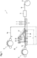
- Figure 1 shows a system 1 in which a first carding machine 2 deposits a carded fleece 2a on a rotating belt 3.
- the carded fleece 2a can consist of viscose fibers with, for example, 1.7 den and 40 mm fiber length.
- a round screen former 20 is arranged downstream, which is designed to produce a layer of wet-laid fibers 24.
- a further carding machine 6, which is also designed to produce a carded fleece 6a can be arranged downstream of the round screen former 20 in the transport direction.
- At least one hydroentanglement device 7 and one dryer 9 are arranged downstream in the transport direction.
- the system 1 is designed to variably produce only one layer of wet-laid fibers 24, a fleece 2a with one layer of wet-laid fibers 24, or a fleece 2a with one layer of wet-laid fibers 24 and another fleece 6a.
- a cylinder former 20 produces a layer of wet-laid fibers 24 and lays them on a rotating belt 3.
- the cylinder former 20 has a headbox 23 through which a fiber suspension, for example made of pulp, is laid on a driven rotating cylinder 22 by means of a line.
- the rotating cylinder 22 can preferably have a perforated jacket with a large number of holes that can be suctioned from the inside.
- a stationary suction device in the rotating cylinder 22 most of the water can be removed from the fiber suspension.
- the resulting water on the The wet fibers 24 deposited on the cylinder 22 are transported away with their upper side by a circulating belt 21, which can preferably be designed as a sieve belt.
- the upper side of the wet fibers 24 is held and transported away by one side of the belt 21, which in this embodiment is directed downwards and thus deposits the wet fibers 24 on the circulating belt 3 with the force of gravity.
- a single-layer fleece is created, which can be solidified, dried and wound up for further processing.
- the layer of wet-laid fibers 24 can preferably be treated with a binder before solidification.
- the system 1 has at least one device for producing a carded fleece, which is arranged in the transport direction before the cylinder former 20.
- the device can be designed as a carding machine 2.
- the layer of wet-laid fibers 24 is deposited on the fleece 2a of the carding machine 2. This creates a two-layer fleece, comprising a layer of carded fleece 2a with a layer of wet-laid fibers 24, which are solidified together, dried and further processed as a fleece 10 or wound up by means of a winder 11.
- the wet-laid fibers 24 can be covered by another carded fleece 6a via another carding machine 6, so that the wet-laid fibers 24 are chambered on both sides by a fleece 2a, 6a.
- the carded fleece 6a can also consist of viscose with 1.7 den and 40 mm fiber length, for example.
- the three layers can then be solidified together, dried and further processed as fleece 10 or wound up using a winder 11.
- the representation of the carding machine 6 above the cylinder former is only schematic. In fact, the system components 2, 20 and 6 are arranged subsequently in the transport direction.
- the representation of the depositing of the fleeces 2a, 6a on one or more circulating belts 3 is also only schematic.
- the carding machine usually deposits the carded fleeces at a slight angle from above the conveyor belt(s).
- the circulating belt 3 mentioned in the invention does not limit the number of circulating belts with which the wet-laid fibers 24 and/or carded webs 2a, 6a are connected. Several circulating belts can also be used.
- the water jet entanglement 7 can be operated in one or more stages at a pressure of 40 - 400 bar, whereby a suction device 8 can be arranged below the circulating belt 3, with which the water from the water jet entanglement 7 is sucked off.
- the consolidated multi-layer fleece then passes through a dryer 9, which can be designed as a drum dryer or belt dryer. After drying, the single- or multi-layer fleece 10 is wound up on a winder 11.
- An advantage of the system 1 according to the invention is the small space requirement for the production of a single- or multi-layer fleece, the even distribution of the wet-laid fibers 24 across the width of the resulting fleece, as well as the possible use of secondary fibers, regenerated fibers and/or recycled fibers, so that a biodegradable fleece can be produced.
- a further advantage is that the system can be operated with only one layer of wet-laid fibers 24, or with two layers (2a and 24) or (24 and 6a) or with three layers (2a and 24 and 6a) of fibers or fleeces and is very inexpensive to operate due to its compactness and low investment costs.
- the distance L between the support points at which the webs 2a and 6a are placed on one or more belts 3 and between which the layer of wet-laid fibers 24 is applied is a maximum of 25 m.
- the distance I between the support point of a web 2a on one or more belts 3 and the point following in the direction of transport at which the wet-laid fibers 24 are placed on the web 2a is a maximum of 10 m. This creates a short and compact system that cannot be achieved by using a classic inclined screen former.
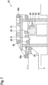
- Figure 2 shows an enlarged view of a first embodiment of the cylinder former 20, in which a fibrous suspension is deposited on a driven rotating cylinder 22 by means of a headbox 23.
- the cylinder 22 can preferably have a perforated jacket and drain the water from the fibrous suspension through it.
- the entire cylinder 22 can be under slight negative pressure and have an outlet for the drained water.
- the cylinder 22 can also be vacuumed at least in the partial area on the circumference on which the belt 21 rests, which is the case in the embodiment of the Figure 2a is described in more detail.
- a suction device (not shown) can be arranged above the cylinder 22, which sucks the water out of the fiber suspension through the circulating belt 21.
- the suction can preferably be varied in strength inside and/or outside the cylinder 22 over a partial circumference in segments.
- the cylinder 22 or the circulating belt 21 can interact with one or more couch rolls (not shown), which ensure further dewatering and compaction of the wet-laid fibers 24.
- the circulating belt 21, which can be designed as a screen belt, is guided around several deflection rollers 28 and rests with an outer side on a partial circumference of the cylinder 22 with tension, so that the water is pressed out of the fiber suspension.
- At least one deflection roller 28 can be designed as a tension roller, with which the circulating belt 21 can be tensioned.
- the cylinder 22 and the belt 21 rotate or move preferably at the same speed.
- a pickup 25 can be arranged on the inner side of the belt 21 in the area where with which the belt 21 separates from the cylinder 22.
- the collector 25 can be designed as a suction chamber so that the fibers 24 remain on the belt 21 under a negative pressure and are removed from the cylinder 22.
- the fibers 24 are thus transported headfirst with their upper side from the belt 21 in the direction of the rotating belt 3, on which the fleece 2a can in turn rest.
- a separating suction device 26 can be arranged on the round screen former 20, with which the fibers are separated from the belt 21 by means of suction air.
- the separating suction device 26 is arranged below the rotating belt 3 and can - if present - flow through the fleece 2a at the same time.
- a pressure device 27 can be arranged to enhance the detachment effect of the fibers 24 from the belt 21, which detaches the fibers 24 from the belt 21 by means of air or water pressure.
- a deflection roller 28a is designed to be adjusted in position so that in the transfer area of the wet-laid fibers 24 to the fleece 2a between the belts 3 and 21 in the transport direction, with which the detachment of the wet-laid fibers 24 from the belt 21 is supported.
- the quality of the wet-laid fibers 24 can be optimized at the headbox 23 by controlling the dilution water, which makes it possible to further even out the cross-section of the wet-laid fibers 24. With a working width of the system of up to 5 m, the cross-section can thus become more uniform, particularly with thin and light layers of wet-laid fibers. A further improvement can be achieved by means of a headbox heater, which can also further improve the cross-section profile of the wet-laid fibers 24.
- the edge of the wet-laid fibers can be made sharper by means of edge suction.
- the cylinder former 20 is mounted on a frame 29, which can optionally be arranged in the area of a feed of further fibers or a fleece 2a above a belt 3.
- the layer of wet-laid fibers can also be deposited with the underside on another conveyor belt that follows the circulating belt 21.
- the cylinder 22 is suctioned at least in a partial area on the circumference, on which the wet-laid fibers 24 are transferred from the headbox 23 to the rotating cylinder and then the fibers are taken over by the belt 21.
- the suction 22a is arranged in a fixed position within the cylinder 22 and is designed in several stages, which can have a central suction in the middle and a suction arranged on either side with reduced suction power.
- a stepped suction device that can decrease continuously or in stages around the circumference of the cylinder from the headbox 23 to the transfer to the belt 21.
- a couch roll 30 above the belt 21 compacts the wet-laid fibers 24 and increases the dry content of the fibers 24.
- a suction device (not shown in detail) can be arranged overhead above the belt 21 in the area where the wet-laid fibers 24 are transferred from the cylinder 22 to the belt 21.
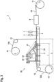
- FIG 3 shows an alternative embodiment in which instead of the carding 2 and/or 6 made of Figure 1 one or two fleeces 12a, 14a can also be unwound from an unwinding station 12, 14 via a deflection roller 13, 15 and introduced into the system 1.
- the fleece 12a, 14a can each have a basis weight of 15 g/m 2 .
- a pulp quantity of 20 g/m 2 that is processed by the round screen former 20 a light multi-layer fleece 10 with a total weight of 50 g/m 2 is produced after the dryer 9.
- the fleece 10 can preferably be used as a biodegradable product for the hygiene or cosmetics sector.
- the fibers of the fleece 12a, 14a can also consist of lyocell, cotton, flax, or other renewable raw materials.
- the use of secondary fibers, regenerated fibers or recycled fibers expands the range of applications of system 1 for producing a biodegradable nonwoven that cannot be achieved with an airlaid or meltblown system.
- the distance L between the support points at which the nonwovens 12a and 14a are placed on one or more belts 3 and between which the layer of wet-laid fibers 24 is applied is a maximum of 25 m.
- the distance I between the support point of a nonwoven 12a on one or more belts 3 and the support point following in the transport direction at which the wet-laid fibers 24 are placed on the nonwoven 12a is a maximum of 10 m. This creates a short and compact system that cannot be achieved by using a classic inclined screen former.
- a further advantage is that the plant can be operated with only one layer of wet-laid fibers 24, or with two layers (12a and 24) or (24 and 14a) or with three layers (12a and 24 and 14a) of fibers or fleeces and is very economical to operate due to its compactness and low investment costs.
- the use of the cylinder former 20 offers the advantage that the wet-laid fibers 24 can be further processed with two smooth or flat surfaces, which are smoothed by the cylinder 22 on the underside and by the belt 21 on the top of the wet-laid fibers 24. Due to the smoothed surfaces, a uniform material distribution or a uniform basis weight is achieved that cannot be achieved with other processes (airlaid, meltblown).
- the advantage of the round wire former 20 compared to the classic inclined wire former is its compactness and low investment and operating costs.
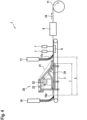
- the alternative embodiment of the system according to Figure 4 shows a further alternative embodiment, in which instead of the carding 2 and/or 6 made of Figure 1 and/or the unwinding stations 12 and/or 14 Figure 3 at least one nonwoven 16a or 17a made of synthetic continuous filaments can be drawn off from at least one spunbond system 16, 17 or spunlace tower and introduced into the system 1.
- the nonwoven 16a, 17a can each have a basis weight of 15 g/m 2 .
- a pulp quantity of 20 g/m 2 that is processed by the cylinder former 20 a light multi-layer nonwoven 10 of a total of 50 g/m 2 results after the dryer 9.
- the nonwoven 10 can have a high water retention capacity with the layer of wet-laid fibers 24 made of pulp and can therefore preferably be used for the hygiene or cosmetics sector.
- the distance L between the support points at which the fleeces 16a and 17a are placed on one or more belts 3 and between which the layer of wet-laid fibers 24 is applied is a maximum of 25 m.
- the distance I between the support point of a fleece 16a on one or more belts 3 and the support point following in the direction of transport at which the wet-laid fibers 24 are placed on the fleece 16a is a maximum of 10 m. This creates a short and compact system that cannot be achieved by using a classic inclined screen former.
- a further advantage is that the system can be operated with just one layer of wet-laid fibers 24, or with two layers (16a and 24) or (24 and 17a) or with three layers (16a and 24 and 17a) of fibers or fleeces and is very inexpensive to operate due to its compactness and low investment costs.
- the embodiment of the Figure 5 differs from the embodiment of the Figure 2 by arranging the couch roll 30 in the transport direction in front of the doffer, so that compaction and dewatering takes place in front of the doffer 25, with which the wet-laid fibers 24 are transferred from the cylinder to the belt 21.
- a suction device 31 is additionally arranged, with which water can be sucked out of the fiber suspension regardless of the design of the cylinder 22 (sucked from the inside or not).
- an angle can be set between the belt 21 and the belt 3, which allows the wet-laid fibers 24 to be transferred to the fleece 2a or directly to the circulating Belt 3 is made easier.
- the tension of the belt 21 can be adjusted via the deflection roller 28a.
- the embodiments of the cylinder former 20 according to the Figures 1 to 6 are particularly advantageous for integration between two carding systems 2, 6 or between two unwinding stations 12, 14 or between two spunbond systems 16, 17 or for any combination of system components (carding, unwinding station, spunbond) where a small space requirement is advantageous.
- a fleece 2a, 12a, 16a can be passed underneath the cylinder former 20, whereby the wet-laid fibers 24 of the cylinder former 20 can be deposited on this fleece 2a, 12a, 16a.
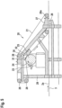
- Figure 6 shows an alternative embodiment of a round screen former 20 with a different viewing direction or side view, in which the belt 3 with the fleece 2a is transported from right to left (transport direction).
- This embodiment is very compact, since the belt 21 of the round screen former 20 is arranged predominantly vertically.
- a fiber suspension is deposited on a driven rotating cylinder 22 by means of a headbox 23.
- the cylinder 22 can preferably have a perforated jacket and drain the water from the fiber suspension through it.
- the entire cylinder 22 can be under slight negative pressure and have an outlet for the drained water.
- the cylinder 22 can also be vacuumed at least in the partial area on the circumference on which the belt 21 rests.
- the rotating belt 21, which can be designed as a screen belt, is guided around several deflection rollers 28 and rests with an outer side on a partial circumference of the cylinder 22 with tension, so that the water is pressed out of the fiber suspension.
- a suction device 31 in the form of a beak suction device sucks at least part of the liquid through the circulating belt 21.
- the belt 21 with the wet-laid fibers 24 is transported from an upside down position to an inclined position by means of a deflection roller 28.
- the deflection roller 28 can be designed by means of an adjustment device so that compaction and further dewatering take place simultaneously in the area of the deflection of the wet-laid fibers.
- At least one deflection roller 28a can be designed as a tension roller with which the circulating belt 21 can be tensioned.
- the cylinder 22 and the belt 21 rotate or move preferably at the same speed.
- the fibers 24 are thus transported upside down with their upper side from the belt 21 in the direction of a deflection roller 28, so that the wet-laid fibers 24 are rotated upwards with their underside by almost 180°.
- the fibers 24 are transported almost vertically downwards and deposited on a circulating belt 3 or a fleece 2a, 12a in the area of an adjustable or pivotable deflection roller 28a.
- the fleece 2a, 12a can be guided completely under the frame 29 of the cylinder former 20 by a belt 3.
- a separating suction device 26 is arranged on the cylinder former 20, with which the fibers are detached from the belt 21.
- the separating suction device 26 is arranged below the rotating belt 3 and can simultaneously flow through the fleece 2a, 12a.
- a pressure device 27 can be arranged to reinforce the detachment effect of the fibers 24 from the belt 21, which detaches the fibers 24 from the belt 21 by means of air or water pressure.
- a deflection roller 28a is designed to be adjusted in position so that in the transfer area of the wet-laid fibers 24 onto the fleece 2a between the belts 3 and 21 in the transport direction, an open angle is created, which supports the detachment of the wet-laid fibers 24 from the belt 21.
- the pivotability of the deflection roller 28a simultaneously facilitates the passage of the fleece 2a, 12a, 16a under the cylinder former.
- Figure 7 shows a further embodiment of a round screen former 20 with a different viewing direction or side view, in which the round screen former 20 is arranged in front of a rotating belt 3 in the transport direction of the wet-laid fibers 24.
- this arrangement is arranged at least partially below the floor, so that the wet-laid fibers 24 produced by the round screen former 20 can be transported approximately horizontally onto a rotating belt 3.
- a fiber suspension is deposited on a driven rotating cylinder 22 by means of a headbox 23.
- the cylinder 22 can preferably have a perforated jacket and drain the water from the fiber suspension through it.
- the entire cylinder 22 can be under slight negative pressure and have an outlet for the drained water.
- the cylinder 22 can also be vacuumed at least in the partial area on the circumference on which the belt 21 rests.
- the circulating belt 21, which can be designed as a sieve belt, is guided around several deflection rollers 28 and rests with an outer side on a partial circumference of the cylinder 22 with tension so that the water is pressed out of the fiber suspension.
- a collector 25 and a subsequent suction device 31 are designed to remove the wet-laid fibers 24 from the cylinder 22 and to hold them on the belt 21 with the top side of the wet-laid fibers 24. At least part of the liquid can be sucked off by the circulating belt 21.
- a further deflection roller 28 is designed to deflect the belt 21 in such a way that the wet-laid fibers 24 are slightly compacted by means of a further deflection roller of the circulating belt 3.
- a separating suction device 26 can be arranged in the transfer area of the wet-laid fibers from the belt 21 to the circulating belt 3, with which the wet-laid fibers 24 are deposited with their underside on the belt 3.
- a deflection roller 28a is designed to be adjusted in position so that in the transfer area of the wet-laid fibers 24 onto the belt 3, an open angle is created between the belts 3 and 21 in the transport direction, with which the detachment of the wet-laid fibers 24 is supported by the belt 21.
- at least one fleece 2a, 6a, 12a, 14a, 16a, 17a can be fed in the transport direction from below or above the belt 3 in order to be connected to the wet-laid fibers 24 by means of hydroentanglement.
- the cylinder former 20 is suitable for a basis weight of 10 to 50 g/m 2 .
- the working speed can be from 50 to 400 m/min.
- the maximum working width can be up to 5 m.
- the subsequent consolidation of one layer of wet-laid fibers 24 or several layers of fleece with the wet-laid fibers 24 for all applications of the Figures 1 to 7 can be done with one or more beams of a water jet entanglement 7 from 40 to 400 bar pressure
- the layer of wet-laid fibers can consist at least partially of short synthetic fibers with a fiber length of 1 to 3 mm, preferably 1 to 12 mm, such as polyester, polyamide, polypropylene or polyolefin. Fiber mixtures of synthetic and natural fibers are also possible.
- the layer of wet-laid fibers can also consist of 100% pulp or other natural fibers that have a high water retention capacity and are preferably biodegradable. The use of secondary fibers, recycled fibers or regenerated fibers is advantageous for the production of biodegradable fibers.
- the fiber suspension can consist of a mixture of fibers with a high proportion of pulp and a smaller proportion of short synthetic fibers with a fiber length of 1 to 3 mm, preferably 1 to 12 mm, such as polyester, polyamide, polyolefin, polypropylene or viscose or lyocell.
- the basis weight of the dried nonwoven 10 can preferably be 20 to 70 g/m 2 .
- the fleece 12a, 14a can consist, for example, of polyester, viscose, a cotton blend or a blend of synthetic and/or natural fibers; for example, one or both fleeces 12a, 14a made of tissue or paper can also be used.
- the basis weight of the fleece 10 is preferably between 20 and 70 g/m 2 .
- the fibers of the fleeces 12a, 14a can consist of short fibers, for example staple fibers with a length of 3 to 60 mm, or of synthetic continuous filaments.
- a very compact and flexible system for producing a single- or multi-layer nonwoven 10, which can consist only of the web of wet-laid fibers 24, or only of the carded nonwoven 2a with or without the carded nonwoven 6a.
- the nonwoven 10 can consist of two or more layers, for example of the wet-laid fibers 24 with one or two webs 2a, 6a of the cards 2 and/or 6, or from the wet-laid fibers 24 with the webs 12a and/or 14a and/or a further web 16a and/or 17a of a spunbond machine 16 and/or 17.
Landscapes
- Engineering & Computer Science (AREA)
- Textile Engineering (AREA)
- Mechanical Engineering (AREA)
- Nonwoven Fabrics (AREA)
- Laminated Bodies (AREA)
Applications Claiming Priority (2)
| Application Number | Priority Date | Filing Date | Title |
|---|---|---|---|
| DE102020113137.2A DE102020113137A1 (de) | 2020-05-14 | 2020-05-14 | Anlage und Verfahren zur Herstellung eines mehrlagigen Vlieses |
| PCT/EP2021/060233 WO2021228514A1 (de) | 2020-05-14 | 2021-04-20 | Anlage und verfahren zur herstellung eines ein- oder mehrlagigen vlieses |
Publications (2)
| Publication Number | Publication Date |
|---|---|
| EP4149751A1 EP4149751A1 (de) | 2023-03-22 |
| EP4149751B1 true EP4149751B1 (de) | 2025-02-12 |
Family
ID=75660011
Family Applications (1)
| Application Number | Title | Priority Date | Filing Date |
|---|---|---|---|
| EP21721034.3A Active EP4149751B1 (de) | 2020-05-14 | 2021-04-20 | Anlage zur herstellung eines mehrlagigen vlieses und verfahren zur herstellung eines vlieses |
Country Status (9)
| Country | Link |
|---|---|
| US (2) | US12338562B2 (pt) |
| EP (1) | EP4149751B1 (pt) |
| DE (1) | DE102020113137A1 (pt) |
| ES (1) | ES3014461T3 (pt) |
| FI (1) | FI4149751T3 (pt) |
| IL (1) | IL299977A (pt) |
| PL (1) | PL4149751T3 (pt) |
| PT (1) | PT4149751T (pt) |
| WO (1) | WO2021228514A1 (pt) |
Families Citing this family (3)
| Publication number | Priority date | Publication date | Assignee | Title |
|---|---|---|---|---|
| FR3078079B1 (fr) * | 2018-02-22 | 2021-02-26 | Andritz Perfojet Sas | Installation de recyclage de nontisse |
| CN115287821A (zh) * | 2022-07-27 | 2022-11-04 | 泉州蓝凯纺织科技有限公司 | 一种新型无纺布生产工艺 |
| DE102024100755A1 (de) * | 2024-01-11 | 2025-07-17 | Trützschler Group SE | Verfahren und Anlage zur Herstellung eines zweilagigen Vlieses |
Family Cites Families (18)
| Publication number | Priority date | Publication date | Assignee | Title |
|---|---|---|---|---|
| US3291682A (en) | 1963-09-16 | 1966-12-13 | Canada Iron Foundries Ltd | Suction cylinder mold for making paper |
| US4443297A (en) * | 1980-08-18 | 1984-04-17 | James River-Dixie/Northern, Inc. | Apparatus and method for the manufacture of a non-woven fibrous web |
| SE455000B (sv) * | 1986-10-20 | 1988-06-13 | Valment Paper Machinery Inc | Anordning vid en rundviramaskins rundviraparti |
| US5587225A (en) | 1995-04-27 | 1996-12-24 | Kimberly-Clark Corporation | Knit-like nonwoven composite fabric |
| SE9703886L (sv) * | 1997-10-24 | 1999-04-25 | Sca Hygiene Paper Ab | Metod för framställning av ett nonwovenmaterial och framställt enligt metoden |
| JP2000034660A (ja) | 1998-07-17 | 2000-02-02 | Uni Charm Corp | 湿式不織布の製造方法および製造装置 |
| US6110848A (en) | 1998-10-09 | 2000-08-29 | Fort James Corporation | Hydroentangled three ply webs and products made therefrom |
| FR2794776B1 (fr) | 1999-06-10 | 2001-10-05 | Icbt Perfojet Sa | Procede pour la realisation d'un materiau non tisse, installation pour sa mise en oeuvre et non tisse ainsi obtenu |
| BR0107640B1 (pt) | 2000-01-17 | 2011-07-12 | método e dispositivo para a produção de materiais de tecido não-tecido por meio de perfuração com agulha hidrodinámica. | |
| BR0110772B1 (pt) * | 2000-05-12 | 2011-01-25 | processo para a produção e formação de tramas de base e produto de papel resultante do mesmo. | |
| DE10303466A1 (de) * | 2003-01-29 | 2004-09-30 | Voith Paper Patent Gmbh | Former |
| US7416638B2 (en) * | 2003-11-18 | 2008-08-26 | Georgia-Pacific Consumer Products Lp | Apparatus and method for manufacturing a multi-layer web product |
| US20050148261A1 (en) * | 2003-12-30 | 2005-07-07 | Kimberly-Clark Worldwide, Inc. | Nonwoven webs having reduced lint and slough |
| DE102005034821A1 (de) | 2005-07-26 | 2007-02-08 | Fleissner Gmbh | Voluminöse Faserlaminate und ihre Herstellung |
| DE202008005526U1 (de) | 2008-04-22 | 2009-02-19 | Wollard & Henry Ltd. | Rundsiebzylinder |
| EP2705186B1 (en) * | 2011-05-04 | 2019-03-13 | Essity Hygiene and Health Aktiebolag | Method of producing a hydroentangled nonwoven material |
| DE102015112955A1 (de) * | 2015-04-13 | 2016-10-13 | TRüTZSCHLER GMBH & CO. KG | Anlage und Verfahren zur Verbindung bzw. Verfestigung einer Bahn von Faserstoff mit einem Vlies |
| DE102020100472A1 (de) * | 2020-01-10 | 2021-07-15 | Andritz Küsters Gmbh | Verfahren zur Herstellung einer Verbundvlieswarenbahn und Vorrichtung zur Herstellung einer Verbundvlieswarenbahn |
-
2020
- 2020-05-14 DE DE102020113137.2A patent/DE102020113137A1/de active Pending
-
2021
- 2021-04-20 PL PL21721034.3T patent/PL4149751T3/pl unknown
- 2021-04-20 US US18/017,428 patent/US12338562B2/en active Active
- 2021-04-20 FI FIEP21721034.3T patent/FI4149751T3/fi active
- 2021-04-20 ES ES21721034T patent/ES3014461T3/es active Active
- 2021-04-20 IL IL299977A patent/IL299977A/en unknown
- 2021-04-20 PT PT217210343T patent/PT4149751T/pt unknown
- 2021-04-20 EP EP21721034.3A patent/EP4149751B1/de active Active
- 2021-04-20 WO PCT/EP2021/060233 patent/WO2021228514A1/de not_active Ceased
-
2024
- 2024-09-20 US US18/891,403 patent/US20250011987A1/en active Pending
Also Published As
| Publication number | Publication date |
|---|---|
| US12338562B2 (en) | 2025-06-24 |
| US20230304200A1 (en) | 2023-09-28 |
| WO2021228514A1 (de) | 2021-11-18 |
| IL299977A (en) | 2023-03-01 |
| PT4149751T (pt) | 2025-03-11 |
| ES3014461T3 (en) | 2025-04-22 |
| EP4149751A1 (de) | 2023-03-22 |
| PL4149751T3 (pl) | 2025-05-19 |
| DE102020113137A1 (de) | 2021-11-18 |
| FI4149751T3 (fi) | 2025-05-16 |
| US20250011987A1 (en) | 2025-01-09 |
Similar Documents
| Publication | Publication Date | Title |
|---|---|---|
| EP2630287B1 (de) | Verfahren und vorrichtung zur herstellung eines verbundvlieses | |
| EP3118361B1 (de) | Anlage und verfahren zur herstellung eines mehrschichtigen vlieses aus mindestens einem unverfestigtem faserflor | |
| EP3017104B1 (de) | Verfahren zum umrüsten und betreiben einer vorrichtung zum herstellen von vliesstoff | |
| EP4149751B1 (de) | Anlage zur herstellung eines mehrlagigen vlieses und verfahren zur herstellung eines vlieses | |
| EP4087967B1 (de) | Verfahren zur herstellung einer verbundvlieswarenbahn und vorrichtung zur herstellung einer verbundvlieswarenbahn | |
| WO2016165798A1 (de) | Anlage und verfahren zur verbindung bzw. verfestigung einer bahn von faserstoff mit einem vlies | |
| EP4087965B1 (de) | Anlage und verfahren zur herstellung eines ein- oder mehrlagigen vlieses | |
| DE102014107725A1 (de) | Verfahren zur Herstellung eines strukturierbaren mehrschichtigen Vlieses und mehrschichtiges Vlies | |
| EP1223135B1 (de) | Vorrichtung zum Transport eines Vlieses zwischen zwei mit Abstand voneinander angeordneten Walzen | |
| DE69609171T3 (de) | Vorrichtung und gerät für die herstellung von vliesen | |
| EP4067548B1 (de) | Anlage zum verfestigen von fasern umfassenden lagen zu einer vliesbahn | |
| EP3495543B1 (de) | Anlage und verfahren zur erzeugung eines spinnvlieses | |
| WO2015000690A1 (de) | Verfahren und kompakte vorrichtung zur herstellung von vliesstoff | |
| EP3017105B1 (de) | Verfahren und vorrichtung zur herstellung von vliesstoff | |
| EP4461859B1 (de) | Anlage und verfahren zur verbindung bzw. verfestigung einer bahn von faserstoff mit einem vlies | |
| WO2015000685A1 (de) | Verfahren und vorrichtung zur herstellung von vliesstoff | |
| EP4444946B1 (de) | Anlage und verfahren zur herstellung eines ein- oder mehrlagigen vlieses | |
| EP1502973A1 (de) | Vlieskrempel und Verfahren zur Herstellung eines Faservlieses | |
| WO2024105099A1 (de) | Faserbehandlungsanlage und faserbehandlungsverfahren | |
| WO2025149196A1 (de) | Verfahren und anlage zur herstellung eines zweilagigen vlieses | |
| WO2015000689A1 (de) | Verfahren und vorrichtung zur herstellung von vliesstoff insbesondere nach einem nassverfahren | |
| DE2542184A1 (de) | Papiermacherfilz sowie verfahren und vorrichtung zur herstellung desselben | |
| WO2015000684A1 (de) | Verfahren und vorrichtung zur herstellung von vliesstoff |
Legal Events
| Date | Code | Title | Description |
|---|---|---|---|
| STAA | Information on the status of an ep patent application or granted ep patent |
Free format text: STATUS: UNKNOWN |
|
| STAA | Information on the status of an ep patent application or granted ep patent |
Free format text: STATUS: THE INTERNATIONAL PUBLICATION HAS BEEN MADE |
|
| PUAI | Public reference made under article 153(3) epc to a published international application that has entered the european phase |
Free format text: ORIGINAL CODE: 0009012 |
|
| STAA | Information on the status of an ep patent application or granted ep patent |
Free format text: STATUS: REQUEST FOR EXAMINATION WAS MADE |
|
| 17P | Request for examination filed |
Effective date: 20230123 |
|
| AK | Designated contracting states |
Kind code of ref document: A1 Designated state(s): AL AT BE BG CH CY CZ DE DK EE ES FI FR GB GR HR HU IE IS IT LI LT LU LV MC MK MT NL NO PL PT RO RS SE SI SK SM TR |
|
| P01 | Opt-out of the competence of the unified patent court (upc) registered |
Effective date: 20230622 |
|
| DAV | Request for validation of the european patent (deleted) | ||
| DAX | Request for extension of the european patent (deleted) | ||
| STAA | Information on the status of an ep patent application or granted ep patent |
Free format text: STATUS: EXAMINATION IS IN PROGRESS |
|
| 17Q | First examination report despatched |
Effective date: 20240208 |
|
| GRAP | Despatch of communication of intention to grant a patent |
Free format text: ORIGINAL CODE: EPIDOSNIGR1 |
|
| STAA | Information on the status of an ep patent application or granted ep patent |
Free format text: STATUS: GRANT OF PATENT IS INTENDED |
|
| R17C | First examination report despatched (corrected) |
Effective date: 20240208 |
|
| INTG | Intention to grant announced |
Effective date: 20241120 |
|
| GRAS | Grant fee paid |
Free format text: ORIGINAL CODE: EPIDOSNIGR3 |
|
| GRAA | (expected) grant |
Free format text: ORIGINAL CODE: 0009210 |
|
| STAA | Information on the status of an ep patent application or granted ep patent |
Free format text: STATUS: THE PATENT HAS BEEN GRANTED |
|
| AK | Designated contracting states |
Kind code of ref document: B1 Designated state(s): AL AT BE BG CH CY CZ DE DK EE ES FI FR GB GR HR HU IE IS IT LI LT LU LV MC MK MT NL NO PL PT RO RS SE SI SK SM TR |
|
| REG | Reference to a national code |
Ref country code: GB Ref legal event code: FG4D Free format text: NOT ENGLISH |
|
| REG | Reference to a national code |
Ref country code: CH Ref legal event code: EP |
|
| REG | Reference to a national code |
Ref country code: DE Ref legal event code: R096 Ref document number: 502021006628 Country of ref document: DE |
|
| REG | Reference to a national code |
Ref country code: PT Ref legal event code: SC4A Ref document number: 4149751 Country of ref document: PT Date of ref document: 20250311 Kind code of ref document: T Free format text: AVAILABILITY OF NATIONAL TRANSLATION Effective date: 20250305 |
|
| REG | Reference to a national code |
Ref country code: IE Ref legal event code: FG4D Free format text: LANGUAGE OF EP DOCUMENT: GERMAN |
|
| REG | Reference to a national code |
Ref country code: ES Ref legal event code: FG2A Ref document number: 3014461 Country of ref document: ES Kind code of ref document: T3 Effective date: 20250422 |
|
| REG | Reference to a national code |
Ref country code: FI Ref legal event code: FGE |
|
| REG | Reference to a national code |
Ref country code: NL Ref legal event code: MP Effective date: 20250212 |
|
| PG25 | Lapsed in a contracting state [announced via postgrant information from national office to epo] |
Ref country code: RS Free format text: LAPSE BECAUSE OF FAILURE TO SUBMIT A TRANSLATION OF THE DESCRIPTION OR TO PAY THE FEE WITHIN THE PRESCRIBED TIME-LIMIT Effective date: 20250512 |
|
| PGFP | Annual fee paid to national office [announced via postgrant information from national office to epo] |
Ref country code: FI Payment date: 20250424 Year of fee payment: 5 |
|
| PGFP | Annual fee paid to national office [announced via postgrant information from national office to epo] |
Ref country code: PL Payment date: 20250411 Year of fee payment: 5 Ref country code: DE Payment date: 20250422 Year of fee payment: 5 |
|
| PGFP | Annual fee paid to national office [announced via postgrant information from national office to epo] |
Ref country code: ES Payment date: 20250530 Year of fee payment: 5 |
|
| REG | Reference to a national code |
Ref country code: LT Ref legal event code: MG9D |
|
| PG25 | Lapsed in a contracting state [announced via postgrant information from national office to epo] |
Ref country code: IS Free format text: LAPSE BECAUSE OF FAILURE TO SUBMIT A TRANSLATION OF THE DESCRIPTION OR TO PAY THE FEE WITHIN THE PRESCRIBED TIME-LIMIT Effective date: 20250612 Ref country code: NO Free format text: LAPSE BECAUSE OF FAILURE TO SUBMIT A TRANSLATION OF THE DESCRIPTION OR TO PAY THE FEE WITHIN THE PRESCRIBED TIME-LIMIT Effective date: 20250512 |
|
| PG25 | Lapsed in a contracting state [announced via postgrant information from national office to epo] |
Ref country code: NL Free format text: LAPSE BECAUSE OF FAILURE TO SUBMIT A TRANSLATION OF THE DESCRIPTION OR TO PAY THE FEE WITHIN THE PRESCRIBED TIME-LIMIT Effective date: 20250212 |
|
| PGFP | Annual fee paid to national office [announced via postgrant information from national office to epo] |
Ref country code: IT Payment date: 20250530 Year of fee payment: 5 |
|
| PG25 | Lapsed in a contracting state [announced via postgrant information from national office to epo] |
Ref country code: HR Free format text: LAPSE BECAUSE OF FAILURE TO SUBMIT A TRANSLATION OF THE DESCRIPTION OR TO PAY THE FEE WITHIN THE PRESCRIBED TIME-LIMIT Effective date: 20250212 |
|
| PG25 | Lapsed in a contracting state [announced via postgrant information from national office to epo] |
Ref country code: LV Free format text: LAPSE BECAUSE OF FAILURE TO SUBMIT A TRANSLATION OF THE DESCRIPTION OR TO PAY THE FEE WITHIN THE PRESCRIBED TIME-LIMIT Effective date: 20250212 |
|
| PGFP | Annual fee paid to national office [announced via postgrant information from national office to epo] |
Ref country code: PT Payment date: 20250410 Year of fee payment: 5 |
|
| PGFP | Annual fee paid to national office [announced via postgrant information from national office to epo] |
Ref country code: FR Payment date: 20250425 Year of fee payment: 5 |
|
| PG25 | Lapsed in a contracting state [announced via postgrant information from national office to epo] |
Ref country code: BG Free format text: LAPSE BECAUSE OF FAILURE TO SUBMIT A TRANSLATION OF THE DESCRIPTION OR TO PAY THE FEE WITHIN THE PRESCRIBED TIME-LIMIT Effective date: 20250212 Ref country code: GR Free format text: LAPSE BECAUSE OF FAILURE TO SUBMIT A TRANSLATION OF THE DESCRIPTION OR TO PAY THE FEE WITHIN THE PRESCRIBED TIME-LIMIT Effective date: 20250513 |
|
| PGFP | Annual fee paid to national office [announced via postgrant information from national office to epo] |
Ref country code: AT Payment date: 20250721 Year of fee payment: 5 |
|
| PGFP | Annual fee paid to national office [announced via postgrant information from national office to epo] |
Ref country code: TR Payment date: 20250505 Year of fee payment: 5 |
|
| PG25 | Lapsed in a contracting state [announced via postgrant information from national office to epo] |
Ref country code: SE Free format text: LAPSE BECAUSE OF FAILURE TO SUBMIT A TRANSLATION OF THE DESCRIPTION OR TO PAY THE FEE WITHIN THE PRESCRIBED TIME-LIMIT Effective date: 20250212 |
|
| PG25 | Lapsed in a contracting state [announced via postgrant information from national office to epo] |
Ref country code: SM Free format text: LAPSE BECAUSE OF FAILURE TO SUBMIT A TRANSLATION OF THE DESCRIPTION OR TO PAY THE FEE WITHIN THE PRESCRIBED TIME-LIMIT Effective date: 20250212 |
|
| PG25 | Lapsed in a contracting state [announced via postgrant information from national office to epo] |
Ref country code: DK Free format text: LAPSE BECAUSE OF FAILURE TO SUBMIT A TRANSLATION OF THE DESCRIPTION OR TO PAY THE FEE WITHIN THE PRESCRIBED TIME-LIMIT Effective date: 20250212 |
|
| PG25 | Lapsed in a contracting state [announced via postgrant information from national office to epo] |
Ref country code: EE Free format text: LAPSE BECAUSE OF FAILURE TO SUBMIT A TRANSLATION OF THE DESCRIPTION OR TO PAY THE FEE WITHIN THE PRESCRIBED TIME-LIMIT Effective date: 20250212 Ref country code: CZ Free format text: LAPSE BECAUSE OF FAILURE TO SUBMIT A TRANSLATION OF THE DESCRIPTION OR TO PAY THE FEE WITHIN THE PRESCRIBED TIME-LIMIT Effective date: 20250212 |
|
| PG25 | Lapsed in a contracting state [announced via postgrant information from national office to epo] |
Ref country code: RO Free format text: LAPSE BECAUSE OF FAILURE TO SUBMIT A TRANSLATION OF THE DESCRIPTION OR TO PAY THE FEE WITHIN THE PRESCRIBED TIME-LIMIT Effective date: 20250212 |
|
| PG25 | Lapsed in a contracting state [announced via postgrant information from national office to epo] |
Ref country code: SK Free format text: LAPSE BECAUSE OF FAILURE TO SUBMIT A TRANSLATION OF THE DESCRIPTION OR TO PAY THE FEE WITHIN THE PRESCRIBED TIME-LIMIT Effective date: 20250212 |
|
| REG | Reference to a national code |
Ref country code: CH Ref legal event code: H13 Free format text: ST27 STATUS EVENT CODE: U-0-0-H10-H13 (AS PROVIDED BY THE NATIONAL OFFICE) Effective date: 20251125 |