EP4149013B1 - Kommunikationsverfahren und -vorrichtung - Google Patents
Kommunikationsverfahren und -vorrichtung Download PDFInfo
- Publication number
- EP4149013B1 EP4149013B1 EP21822865.8A EP21822865A EP4149013B1 EP 4149013 B1 EP4149013 B1 EP 4149013B1 EP 21822865 A EP21822865 A EP 21822865A EP 4149013 B1 EP4149013 B1 EP 4149013B1
- Authority
- EP
- European Patent Office
- Prior art keywords
- terminal device
- network transmission
- quality information
- transmission quality
- network
- Prior art date
- Legal status (The legal status is an assumption and is not a legal conclusion. Google has not performed a legal analysis and makes no representation as to the accuracy of the status listed.)
- Active
Links
Images


Classifications
-
- H—ELECTRICITY
- H04—ELECTRIC COMMUNICATION TECHNIQUE
- H04B—TRANSMISSION
- H04B7/00—Radio transmission systems, i.e. using radiation field
- H04B7/02—Diversity systems; Multi-antenna system, i.e. transmission or reception using multiple antennas
- H04B7/04—Diversity systems; Multi-antenna system, i.e. transmission or reception using multiple antennas using two or more spaced independent antennas
- H04B7/06—Diversity systems; Multi-antenna system, i.e. transmission or reception using multiple antennas using two or more spaced independent antennas at the transmitting station
- H04B7/0613—Diversity systems; Multi-antenna system, i.e. transmission or reception using multiple antennas using two or more spaced independent antennas at the transmitting station using simultaneous transmission
- H04B7/0615—Diversity systems; Multi-antenna system, i.e. transmission or reception using multiple antennas using two or more spaced independent antennas at the transmitting station using simultaneous transmission of weighted versions of same signal
- H04B7/0619—Diversity systems; Multi-antenna system, i.e. transmission or reception using multiple antennas using two or more spaced independent antennas at the transmitting station using simultaneous transmission of weighted versions of same signal using feedback from receiving side
- H04B7/0621—Feedback content
- H04B7/0626—Channel coefficients, e.g. channel state information [CSI]
-
- H—ELECTRICITY
- H04—ELECTRIC COMMUNICATION TECHNIQUE
- H04B—TRANSMISSION
- H04B7/00—Radio transmission systems, i.e. using radiation field
- H04B7/02—Diversity systems; Multi-antenna system, i.e. transmission or reception using multiple antennas
- H04B7/04—Diversity systems; Multi-antenna system, i.e. transmission or reception using multiple antennas using two or more spaced independent antennas
- H04B7/0413—MIMO systems
- H04B7/0452—Multi-user MIMO systems
-
- H—ELECTRICITY
- H04—ELECTRIC COMMUNICATION TECHNIQUE
- H04B—TRANSMISSION
- H04B7/00—Radio transmission systems, i.e. using radiation field
- H04B7/02—Diversity systems; Multi-antenna system, i.e. transmission or reception using multiple antennas
- H04B7/04—Diversity systems; Multi-antenna system, i.e. transmission or reception using multiple antennas using two or more spaced independent antennas
- H04B7/06—Diversity systems; Multi-antenna system, i.e. transmission or reception using multiple antennas using two or more spaced independent antennas at the transmitting station
- H04B7/0613—Diversity systems; Multi-antenna system, i.e. transmission or reception using multiple antennas using two or more spaced independent antennas at the transmitting station using simultaneous transmission
- H04B7/0615—Diversity systems; Multi-antenna system, i.e. transmission or reception using multiple antennas using two or more spaced independent antennas at the transmitting station using simultaneous transmission of weighted versions of same signal
- H04B7/0619—Diversity systems; Multi-antenna system, i.e. transmission or reception using multiple antennas using two or more spaced independent antennas at the transmitting station using simultaneous transmission of weighted versions of same signal using feedback from receiving side
- H04B7/0621—Feedback content
- H04B7/0632—Channel quality parameters, e.g. channel quality indicator [CQI]
-
- H—ELECTRICITY
- H04—ELECTRIC COMMUNICATION TECHNIQUE
- H04L—TRANSMISSION OF DIGITAL INFORMATION, e.g. TELEGRAPHIC COMMUNICATION
- H04L1/00—Arrangements for detecting or preventing errors in the information received
- H04L1/0001—Systems modifying transmission characteristics according to link quality, e.g. power backoff
- H04L1/0002—Systems modifying transmission characteristics according to link quality, e.g. power backoff by adapting the transmission rate
- H04L1/0003—Systems modifying transmission characteristics according to link quality, e.g. power backoff by adapting the transmission rate by switching between different modulation schemes
-
- H—ELECTRICITY
- H04—ELECTRIC COMMUNICATION TECHNIQUE
- H04L—TRANSMISSION OF DIGITAL INFORMATION, e.g. TELEGRAPHIC COMMUNICATION
- H04L1/00—Arrangements for detecting or preventing errors in the information received
- H04L1/0001—Systems modifying transmission characteristics according to link quality, e.g. power backoff
- H04L1/0009—Systems modifying transmission characteristics according to link quality, e.g. power backoff by adapting the channel coding
-
- H—ELECTRICITY
- H04—ELECTRIC COMMUNICATION TECHNIQUE
- H04L—TRANSMISSION OF DIGITAL INFORMATION, e.g. TELEGRAPHIC COMMUNICATION
- H04L1/00—Arrangements for detecting or preventing errors in the information received
- H04L1/0001—Systems modifying transmission characteristics according to link quality, e.g. power backoff
- H04L1/0015—Systems modifying transmission characteristics according to link quality, e.g. power backoff characterised by the adaptation strategy
- H04L1/0019—Systems modifying transmission characteristics according to link quality, e.g. power backoff characterised by the adaptation strategy in which mode-switching is based on a statistical approach
- H04L1/0021—Systems modifying transmission characteristics according to link quality, e.g. power backoff characterised by the adaptation strategy in which mode-switching is based on a statistical approach in which the algorithm uses adaptive thresholds
-
- H—ELECTRICITY
- H04—ELECTRIC COMMUNICATION TECHNIQUE
- H04L—TRANSMISSION OF DIGITAL INFORMATION, e.g. TELEGRAPHIC COMMUNICATION
- H04L1/00—Arrangements for detecting or preventing errors in the information received
- H04L1/0001—Systems modifying transmission characteristics according to link quality, e.g. power backoff
- H04L1/0023—Systems modifying transmission characteristics according to link quality, e.g. power backoff characterised by the signalling
- H04L1/0026—Transmission of channel quality indication
Definitions
- This application relates to the field of communication technologies, and in particular, to a communication method, an apparatus, a computer readable storage medium, a computer program product and a chip that are related to an extended reality (extended reality, XR) service.
- extended reality extended reality
- XR XR
- VR virtual reality
- AR augmented reality
- MR mixed reality
- GUOCHAO SONG ET AL "KPl/KQl-Driven Coordinated Multi-Point in 5G: Measurements, Field Trials, and Technical Solutions”
- ARXIVORG CORNELL UNIVERSITY LIBRARY, 201 OLIN LIBRARY CORNELL UNIVERSITY ITHACA, NY 14853, 16 April 2019 (2019-04-16), XP081169861 , discloses a KPI/KQI-driven CoMP architecture that fulfills KPI requirements and provides KQI guarantee for each user.
- This application provides a data communication method, to maximize XR experience, improve XR experience of a user, and ensure a quantity of XR users satisfied with the XR experience in a system.
- "at least one” means one or more, and "a plurality of” means two or more than two.
- the term “and/or” describes an association relationship between associated objects, and indicates that three relationships may exist. For example, A and/or B may indicate the following cases: Only A exists, both A and B exist, and only B exists, where A and B may be singular or plural.
- the character “/” generally indicates an “or” relationship between the associated objects.
- “At least one item (piece) of the following” or a similar expression thereof indicates any combination of these items, including any combination of singular items (pieces) or plural items (pieces).
- At least one (piece) of a, b, or c may represent a, b, c, a and b, a and c, b and c, or a, b, and c, where each of a, b, and c may be an element, or may be a set including one or more elements.
- communication and transmission may be interchangeably used sometimes. It should be noted that meanings expressed by the terms are consistent when differences are not emphasized.
- transmitting may include sending and/or receiving, and may be a noun or a verb.
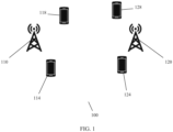
- FIG. 1 is a schematic diagram of a possible architecture of a communication system applied to an embodiment of this application.
- a communication system 100 includes one or more network devices (a network device 110 and a network device 120 shown in the figure), and one or more terminal devices that communicate with the one or more network devices.
- a terminal device 114 and a terminal device 118 shown in FIG. 1 communicate with the network device 110, and a terminal device 124 and a terminal device 128 shown in FIG. 1 communicate with the network device 120. It may be understood that the network device and the terminal device may also be referred to as communication devices.
- the communication system 100 may be various communication systems, for example, a 4th generation (4th generation, 4G) communication system, a 4.5G communication system, a 5G communication system, a system converged by a plurality of communication systems, and a future evolved communication system (for example, a 6G communication system).
- the communication system may be a long term evolution (long term evolution, LTE) system, a new radio (new radio, NR) system, a wireless fidelity (wireless fidelity, Wi-Fi) system, a wireless self-organizing system, a device-to-device direct communication system, a communication system related to the 3rd Generation Partnership Project (3rd generation partnership project, 3GPP), and another communication system of this type.
- FIG. 2 shows a schematic diagram of a structure of an NR system.
- a network device in a radio access network includes a network device (for example, a gNodeB or a gNB) with an architecture in which a central unit (central unit, CU) and a distributed unit (distributed unit, DU) are separated.
- the RAN may be connected to a core network (for example, may be an LTE core network or an NR core network), and the core network may be connected to a server (server).
- the server is a device that provides computing or application services. It may be understood that the network device is divided into the CU and the DU from the perspective of a logical function.
- the CU and the DU may be physically separated or deployed together.
- a plurality of DUs may share one CU.
- One DU may alternatively be connected to a plurality of CUs (not shown in the figure).
- the CU and the DU may be connected through an interface, for example, an F1 interface.
- the CU and the DU may be obtained through division based on protocol layers of a wireless network.
- a packet data convergence protocol packet data convergence protocol
- RRC radio resource control
- functions of a packet data convergence protocol (packet data convergence protocol, PDCP) layer and a radio resource control (radio resource control, RRC) layer are distributed to the CU, but functions of a radio link control (radio link control, RLC) layer, a media access control (media access control, MAC) layer, and a physical (physical) layer are distributed to the DU.
- RLC radio link control
- MAC media access control
- MAC media access control
- DU physical (physical) layer
- division into processing functions of the CU and the DU based on the protocol layers is merely an example, and there may be other division.
- the CU or the DU may have functions of more protocol layers through division.
- the CU or the DU may alternatively have some processing functions of the protocol layers through division.
- functions of the RLC layer and functions of a protocol layer above the RLC layer are distributed to the CU, and remaining functions of the RLC layer and functions of a protocol layer below the RLC layer are distributed to the DU.
- functions of the CU or the DU may alternatively be obtained through division based on a service type or another system requirement. For example, division is performed based on a latency, a function whose processing time needs to satisfy a latency requirement is disposed on the DU, and a function whose processing time does not need to satisfy the latency requirement is disposed on the CU.
- the network architecture shown in FIG. 2 may be applied to the NR system, and may alternatively share one or more components or resources with an LTE system.
- the CU may alternatively have one or more functions of the core network.
- One or more CUs may be disposed in a centralized manner or a separated manner.
- the CUs may be disposed on a network side for ease of centralized management.
- the DU may have a plurality of radio frequency functions, or the radio frequency functions may be disposed remotely.
- the function of the CU may be implemented by one entity, or may be used to further separate a control plane (CP) and a user plane (UP).
- CP control plane
- UP user plane
- the control plane of the CU (CU-CP) and the user plane of the CU (CU-UP) may be implemented by different function entities, and the CU-CP and the CU-UP may be coupled to the DU to jointly implement a function of a base station.
- the network device is connected to one or more terminal devices through an air interface, to perform data communication.
- the network device and the terminal device may further communicate with each other by using a relay device (Relay).
- the relay device may be a small cell similar to a base station, for example, an integrated access and backhaul (integrated access and backhaul, IAB) base station, or a terminal device.
- IAB integrated access and backhaul
- FIG. 3 is a schematic diagram of a structure of a Wi-Fi system.
- a server performs data communication with a terminal device by using an operator network through a Wi-Fi router (or a Wi-Fi access point).
- a function of the Wi-Fi access point is to enable the terminal device to enter a wired network.
- FIG. 4 shows a schematic diagram of a structure of a device-to-device direct communication system.
- two terminal devices may directly communicate with each other through a sidelink (Sidelink), and the sidelink is used for communication between terminal devices.
- Sidelink Sidelink
- the terminal device may be referred to as a terminal for short, and is a device having a wireless transceiver function.
- the terminal device may be deployed on land, including being deployed indoor or outdoor or being handheld or vehicle-mounted; may be deployed on water (for example, on a ship); or may be deployed in the air (for example, on a plane, a balloon, or a satellite).
- the terminal device may be a mobile phone (mobile phone), a tablet computer (pad), a computer having a wireless transceiver function, a wireless terminal device in industrial control (industrial control), a wireless terminal device in self driving (self driving), a wireless terminal device in telemedicine (remote medical), a wireless terminal device in a smart grid (smart grid), a wireless terminal device in transportation safety (transportation safety), a wireless terminal device in a smart city (smart city), a wireless terminal device in a smart home (smart home), user equipment (user equipment, UE), or the like.
- a mobile phone mobile phone
- tablet computer pad
- a computer having a wireless transceiver function a wireless terminal device in industrial control (industrial control), a wireless terminal device in self driving (self driving), a wireless terminal device in telemedicine (remote medical), a wireless terminal device in a smart grid (smart grid), a wireless terminal device in transportation safety (transportation safety), a wireless terminal device in a smart city (smar
- the terminal device may be a cellular phone, a cordless phone, a session initiation protocol (session initiation protocol, SIP) phone, a wireless local loop (wireless local loop, WLL) station, a personal digital assistant (personal digital assistant, PDA), a handheld device having a wireless communication function, a computing device or another processing device connected to a wireless modem, a vehicle-mounted device, a wearable device, a terminal device in a future 5th generation (5th generation, 5G) network, a terminal device in a future evolved public land mobile network (public land mobile network, PLMN), or the like.
- SIP session initiation protocol
- WLL wireless local loop
- PDA personal digital assistant
- the terminal device may also be referred to as a terminal, user equipment (user equipment, UE), an access terminal device, a vehicle-mounted terminal device, an industrial control terminal device, a UE unit, a UE station, a mobile station, a mobile station, a remote station, a remote terminal device, a mobile device, a UE terminal device, a terminal device, a wireless communication device, a UE agent, a UE apparatus, or the like.
- UE user equipment
- UE user equipment
- an access terminal device a vehicle-mounted terminal device
- an industrial control terminal device a UE unit, a UE station, a mobile station, a mobile station, a remote station, a remote terminal device, a mobile device, a UE terminal device, a terminal device, a wireless communication device, a UE agent, a UE apparatus, or the like.
- the terminal device may alternatively be an XR terminal device, including a VR terminal device, an AR terminal device, and an MR terminal device.
- the XR terminal may be, for example, a head mounted device (for example, a helmet or glasses), may be an all-in-one machine, or may be a television, a display, a car, a vehicle-mounted device, a tablet, or a smart screen.
- the XR terminal can present XR data to a user, and the user can experience diversified XR services by wearing or using the XR terminal.
- the XR terminal may access a network in a wireless or wired manner, for example, by using a Wi-Fi or 5G system.
- the terminal device may be fixed or mobile. This is not limited in embodiments of this application.
- an apparatus configured to implement a function of a terminal device may be a terminal device; or may be an apparatus, for example, a chip system, that can support the terminal device in implementing the function.
- the apparatus may be installed in the terminal device.
- the chip system may include a chip, or may include a chip and another discrete component.
- the network device may be an access network device.
- the access network device may also be referred to as a radio access network (radio access network, RAN) device, and is a device that provides a wireless communication function for the terminal device.
- the network device includes but is not limited to: a next-generation base station (generation NodeB, gNB) in 5G, an evolved NodeB (evolved NodeB, eNB), a radio network controller (radio network controller, RNC), a NodeB (NodeB, NB), a base station controller (base station controller, BSC), a base transceiver station (base transceiver station, BTS), a home base station (for example, a home evolved NodeB or a home NodeB, HNB), a baseband unit (baseband unit, BBU), a transmission reception point (transmission reception point, TRP), a transmission point (transmission point, TP), and a mobile switching center.
- generation NodeB generation NodeB
- eNB
- the network device may be a radio controller, a central unit (central unit, CU), and/or a distributed unit (distributed unit, DU) in a cloud radio access network (cloud radio access network, CRAN) scenario, or the network device may be a relay station, an access point, a vehicle-mounted device, a terminal device, a wearable device, a network device in a future 5G network, a network device in a future evolved PLMN network, or the like.
- the terminal device may communicate with a plurality of network devices using different technologies.
- the terminal device may communicate with a network device supporting long term evolution (long term evolution, LTE), may communicate with a network device supporting 5G, or may implement dual connectivity with a network device supporting LTE and a network device supporting 5G. This is not limited in embodiments of this application.
- LTE long term evolution
- 5G network device supporting 5G
- an apparatus configured to implement functions of the network device may be a network device, or may be an apparatus, for example, a chip system, that can support the network device in implementing the functions.
- the apparatus may be installed in the network device.
- An air interface is a Uu interface, and may be referred to as Uu for short.
- the Uu air interface is used for communication between the terminal device and the network device. Transmission over the Uu air interface may include uplink transmission and downlink transmission.
- the uplink information or the uplink signal may include one or more of an uplink data signal, an uplink control signal, and a sounding reference signal (sounding reference signal, SRS).
- a channel used to transmit the uplink information or the uplink signal is referred to as an uplink channel, and the uplink channel may include one or more of a physical uplink data channel (physical uplink shared channel, PUSCH) and a physical uplink control channel (physical uplink control channel, PUCCH).
- the PUSCH is used to carry uplink data, and the uplink data may also be referred to as the uplink data information.
- the PUCCH is used to carry uplink control information (uplink control information, UCI) fed back by the terminal device.
- the UCI may include one or more of channel state information (channel state information, CSI), an ACK, a NACK, and the like that are fed back by the terminal device.
- the downlink information or the downlink signal may include one or more of a downlink data signal, a downlink control signal, a channel state information reference signal (channel state information reference signal, CSI-RS), and a phase tracking reference signal (phase tracking reference signal, PTRS).
- a channel used to transmit downlink information or a downlink signal is referred to as a downlink channel, and the downlink channel may include one or more of a physical downlink data channel (physical downlink shared channel, PDSCH) and a physical downlink control channel (physical downlink control channel, PDCCH).
- the PDCCH is used to carry downlink control information (downlink control information, DCI), and the PDSCH is used to carry downlink data (data).
- the downlink data may also be referred to as downlink data information.
- XR service and XR experience Data of an XR service includes one or more of VR data, AR data, MR data, video data, audio data, or picture data.
- the XR service may be considered as a fourth-type service in a post-5G or 6G communication system, and may be referred to as a fourth-pole service for short.
- An enhanced mobile broadband (enhanced mobile broadband, eMBB) service has a high requirement on a data rate
- a massive machine type communication (massive machine type communication, mMTC) service has a high requirement on coverage and a capacity
- an ultra-reliable low-latency communication ultra-reliable low-latency communication (ultra-reliable low-latency communication, URLLC) service has a high requirement on a latency and reliability.
- eMBB enhanced mobile broadband
- mMTC massive machine type communication
- URLLC ultra-reliable low-latency communication
- the XR service has a requirement for a low delay and a high rate.
- the XR service focuses on user experience, which may also be referred to as XR experience.
- the XR experience includes immersive experience, visual experience, interaction experience, device experience, or the like.
- the XR experience may be evaluated from a plurality of different dimensions, for example, including one or more of the following dimensions: image definition, image smoothness, image distortion, image stereoscopy, image black borders, image smearing, sound quality, sound effect, angle of view, freezing, artifacts, dizziness, audio and video synchronization, interaction freedom, interaction operation response speed, interaction operation precision, interaction content loading speed, terminal wearing comfort, terminal wearing fatigue, terminal battery life, terminal portability, terminal visual impairment friendliness, or the like. Evaluating the XR experience and identifying experience bottlenecks promotes optimization of network transmission, XR source content, and terminals, and can effectively promote development of an end-to-end industry.
- advantages and disadvantages of the XR experience may be quantified by using an XR experience value. For example, if the XR experience value is high, user experience is good; or if the XR experience value is low, user experience is poor. Further, a threshold may be set for the XR experience value, and the threshold may represent an XR experience requirement. It should be noted that, in embodiments of this application, the XR experience and the XR experience value are sometimes used alternately, but a person skilled in the art may understand the meanings thereof.
- a principle of maximizing a throughput is used for data scheduling transmission, and a pairing principle and a scheduling transmission manner that support multi-user multiple-input multiple-output (multi-user multiple-input multiple-output, MU-MIMO) are as follows: Terminal devices that meet a signal to interference plus noise ratio requirement participate in pairing. It is assumed that a terminal device A and a terminal device B participate in pairing. A rate of independently scheduling the terminal device A is 100 megabits per second (Mbps), and a rate of independently scheduling the terminal device B is also 100 Mbps.
- Mbps megabits per second
- a rate of independently scheduling the terminal device B is also 100 Mbps.
- a sum rate of scheduling the terminal device A and the terminal device B at the same time based on the principle of maximizing the throughput is 160 Mbps.
- the rates are reduced. For example, rates of respectively scheduling the terminal device A and the terminal device B are reduced to 80 Mbps. Consequently, XR experience of the terminal device A and the terminal device B may deteriorate. Therefore, in comparison with independently scheduling any terminal device, when the terminal device A and the terminal device B are paired for scheduling, a rate of scheduling any terminal device decreases.
- the data of the XR service is video data
- phenomena such as video freezing and black borders may occur, thereby affecting subjective experience (an XR experience value) of a user.
- an XR experience value decreases to a threshold
- a quantity of XR users satisfied with the XR experience eventually decreases.
- a block error rate (block error rate, BLER) indicator of transmission is determined based on a quality of service (quality of service, QoS) requirement configured on a core network side, including an initial transmission BLER and a retransmission BLER.
- An initial modulation and coding (modulation and coding scheme, MCS) index is selected and a scheduling resource is allocated for each transport block of a terminal device based on the BLER indicator and channel state information (channel state information, CSI) fed back by the terminal device.
- MCS modulation and coding scheme
- CSI channel state information
- an MCS is adjusted based on CSI information fed back by the terminal device and a statistical hybrid automatic repeat request (hybrid automatic repeat request, HARQ) feedback result, to ensure transmission correctness, and maximize system throughput.
- HARQ hybrid automatic repeat request
- the threshold of the XR experience value is A
- the XR experience value of user equipment obtained by the network device at a current scheduling moment is B
- B ⁇ A the network device determines the MCS index and allocation of the scheduling resource based on a CSI feedback. It is assumed that the CSI feedback indicates that the MCS index increases from 20 to 25. In this case, a possible consequence is that the BLER still cannot meet a corresponding XR experience requirement, and even the XR experience value decreases from B to C, that is, C ⁇ B ⁇ A. Consequently, the quantity of XR users satisfied with the XR experience eventually decreases.
- An XR service usually has a higher priority than a common service. Therefore, for the XR service, the foregoing problem in the communication system, that the XR experience is poor and the quantity of users of the XR service satisfied with the XR experience decreases due to the single objective of maximizing the throughput, needs to be resolved.
- an evaluation parameter of the XR experience may be defined.
- the evaluation parameter of the XR experience may include network transmission quality information used to evaluate communication quality of data of the XR service (XR data for short hereinafter) during network transmission, or in other words, used to evaluate the communication quality of the XR data on the network side.
- the network transmission includes RAN transmission and core network transmission.
- the network side includes a RAN and a core network.
- the network transmission quality information may also be referred to as (or include) an XR quality index (XR quality index, XQI).
- the network transmission quality information uses technical statistics that can be obtained during network transmission to fit impact of the network transmission side on a subjective experience score of a user. In this way, impact of the network transmission side on the XR experience can be evaluated, and operators can use this indicator to guide network upgrade, networking, and network construction.
- the technical statistics that can be obtained by the network transmission side include: a packet error rate (packet error rate, PER) and/or a BLER, a packet delay budget (Packet Delay Budget, PDB), a delay jitter value, retransmission information, a transmission rate, and the like.
- Network transmission quality information f(PER, PDB, delay jitter, retransmission information), where f() represents a function expression.
- the network transmission quality information can provide an evaluation manner more flexible than evaluating the XR experience directly based on whether the PER and/or the BLER and the PDB are met. In embodiments of this application, it may be considered that the XR experience is mainly reflected by the network transmission quality information.
- the network transmission quality information may include the XR experience value (or referred to as an XQI experience value), or the network transmission quality information (sometimes referred to as an XQI) and the XR experience value may be interchanged sometimes.
- a threshold that is set for the XR experience value namely, an XR experience requirement, may also be referred to as a network transmission quality information threshold (or an XQI threshold), representing a network transmission quality requirement (or an XQI requirement).
- the network transmission quality information is essentially communication quality of XR data in a network sensed by a terminal device, and the XR experience is essentially experience of the terminal device in XR data communication. Therefore, the network transmission quality information and the XR experience may also be referred to as network transmission quality information of the terminal device and XR experience of the terminal device.
- a network device may manage data communication with user equipment based on at least the network transmission quality information, fully consider the XR experience, and improve the XR experience as much as possible, further to increase the quantity of XR users satisfied with the XR experience.
- FIG. 5 shows a communication method according to this application. Subsequent embodiments of this application may provide descriptions in detail based on the communication method.
- Step 501 A network device obtains network transmission quality information and channel state information (channel state information, CSI), where the network transmission quality information indicates communication quality of XR data during network transmission.
- channel state information channel state information, CSI
- Step 502 The network device manages a data communication manner based on the network transmission quality information and the CSI.
- an object managed by the network device may be a terminal device.
- the network device manages a manner of data communication with the terminal device.
- the terminal device accepts management performed by the network device on the data communication manner.
- This management on the data communication manner may be embodied through communication between the network device and the terminal device.
- a manner of obtaining the network transmission quality information by the network device may be receiving the network transmission quality information sent by the terminal device, may be receiving a parameter (for example, at least one of the foregoing PER, PDB, delay jitter value, retransmission information, and transmission rate) that is sent by the terminal device and that is related to calculation of the network transmission quality information and then obtaining the network transmission quality information through calculation of the network device, may be receiving the network transmission quality information sent by a core network, or may be another manner.
- a manner of obtaining the CSI by the network device may be similar to a manner of obtaining the CSI by the network device in a current technology. For example, the network device receives the CSI sent by the terminal device, where the CSI is obtained by the terminal device by measuring a reference signal sent by the network device.
- Embodiment 1 to Embodiment 4 may include all content related to the communication method in FIG. 5 .
- the network device manages the data communication manner, where the data communication manner may include a data communication manner that is based on multiple-input multiple-output (multiple-input multiple-output, MIMO).
- the network device may determine, based on the network quality transmission information and the CSI, a data communication manner used when performing data communication with the terminal device by using MIMO.
- the data communication includes at least XR data communication.
- MIMO communication may include MU-MIMO communication and single-user multiple-input multiple-output (single-user multiple-input multiple-output, SU-MIMO) communication
- the network device may determine pairing between different users based on MU-MIMO (for example, a pairing criterion between different users), a scheduling sequence for different terminal devices based on SU-MIMO, and the like.
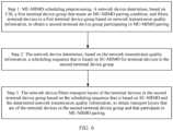
- step 502 The following describes related content of step 502 in detail with reference to FIG. 6 .
- the MIMO data communication manner mainly includes the following three steps.
- Step 1 The network device determines, based on the CSI, a first terminal device group that meets an MU-MIMO pairing condition, and filters terminal devices in the first terminal device group based on the network transmission quality information, to obtain a second terminal device group participating in MU-MIMO pairing.
- the network device determines, based on the CSI (or an uplink reference signal sent by the terminal device), correlation between downlink channels of terminal devices in a user equipment service, and filters the terminal devices based on beam information of the terminal devices, to exclude terminal devices that do not meet a basic condition for MU-MIMO pairing.
- the pairing means that: if different users transmit data on a same time-frequency resource in a spatial multiplexing manner, it may be referred to that the different users are paired on the same time-frequency resource.
- the basic condition for MU-MIMO pairing may be that correlation between downlink channels of different terminal devices is less than a correlation threshold.
- Terminal devices that meet the basic condition for MU-MIMO pairing and that are obtained through filtering in this way may be grouped into the first terminal device group.
- the network device further filters the terminal devices in the first terminal device group based on the network transmission quality information. For example, a threshold (a network transmission quality requirement) may be set for the network transmission quality information.
- the terminal device can be allowed to participate in MU-MIMO pairing, only when a network transmission quality information corresponding to a terminal device meets the threshold. In this way, terminal devices that are obtained through further filtering and that are allowed to participate in MU-MIMO pairing are grouped into the second terminal device group.
- the network device may further determine a quantity of initial transport layers and/or a rank of the initial transport layers of the terminal device in the second terminal device group before the terminal device participates in MU-MIMO pairing.
- a quantity of codewords may not be equal to the quantity of layers.
- a process of mapping a codeword to a layer is layer mapping.
- the "layer” herein is the transport layer.
- One transport layer corresponds to one radio transmit mode.
- a quantity of used transport layers is referred to as the rank.
- This step may be considered as preprocessing of MU-MIMO scheduling.
- Step 2 The network device determines, based on the network transmission quality information, a scheduling sequence that is based on SU-MIMO for the terminal devices in the second terminal device group. In other words, the network device determines scheduling priorities of the terminal devices in the second terminal device group.
- the network device may preferentially schedule the terminal device, or in other words, a scheduling priority based on SU-MIMO of the terminal device is high, or a scheduling sequence that is based on SU-MIMO of the terminal device is ranked first. Based on a similar rule, the network device completes SU-MIMO scheduling sorting on the terminal devices in the second terminal device group.
- a specific SU-MIMO scheduling procedure is similar to an existing mechanism, and details are not described in this embodiment of this application.
- the network device updates, based on the determined SU-MIMO scheduling sequence, a quantity of transport layers that are of the terminal devices in the second terminal device group and that participate in MU-MIMO pairing.
- Step 3 The network device filters the transport layers of the terminal devices in the second terminal device group based on the scheduling sequence that is based on SU-MIMO and the network transmission quality information that are determined in step 2, to obtain transport layers that are of the terminal devices in the second terminal device group and that participate in MU-MIMO pairing.
- the network device traverses resource block groups (resource block groups, RBGs) allocated to the terminal devices in the second terminal device group and transport layers of the terminal devices.
- RBGs resource block groups
- the network device separately obtains estimated network transmission quality information corresponding to the different transport layers based on the RBGs and current network transmission quality information of the terminal device. Then the network device separately filters the transport layers based on whether estimated network transmission quality information corresponding to the different transport layers meets a preset threshold, to obtain transport layers participating in pairing. If the estimated network transmission quality information meets the preset threshold, the corresponding used transport layer can participate in MU-MIMO pairing.
- the network device updates a quantity of transport layers and/or a rank of transport layers that are of the terminal devices in the second terminal device group and that participate in MU-MIMO pairing.
- the network device performs MIMO data communication with the terminal device based on the foregoing three steps.
- that the terminal device accepts management performed by the network device on the data communication manner may be reflected in the MIMO data communication with the network device with reference to the foregoing steps.
- the network device determines policies such as pairing and scheduling for performing MIMO data communication with the terminal device, aiming to maximize the XR experience, thereby effectively improving the XR experience, and ensuring a quantity of XR users satisfied with the XR experience.
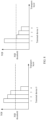
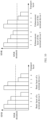
- FIG. 7 shows signal to interference plus noise ratios (signal to interference plus noise ratios, SINRs) of transport layers of a terminal device 0 and a terminal device 1 before pairing.
- SINRs signal to interference plus noise ratios
- FIG. 8 shows estimated network transmission quality information of the terminal device before each transport layer of the terminal device 0 and the terminal device 1 participates in pairing.
- an XQI is used as an example to perform MU-MIMO pairing in a manner in this embodiment of this application.
- a quantity of terminal devices satisfied with XR experience in a system is largest, the terminal device 0 meets an XR experience requirement (the XQI is higher than a preset threshold), and resources (for example, time-frequency resources and/or space domain resources) that can participate in MU-MIMO pairing are largest.
- three transport layers of the terminal device 0, namely, transport layers 1, 2, and 3, are selected.
- one transport layer of the terminal device 1 participates in pairing, a quantity of users satisfied with XR experience in a system is largest, the terminal device 1 meets an XR experience requirement (the XQI is higher than a preset threshold), and resources (for example, time-frequency resources and/or space domain resources) that can participate in MU-MIMO pairing are largest.
- one transport layer of the terminal device 1, namely, a transport layer 1 is the selected.
- layering source data transmitted from a network application layer is not considered.
- a scenario of layering source data may be further considered.
- the source data described herein refers to original bit data for generating XR data.
- Layers in the layering herein refer to two or more layers of data (which may also be referred to as two-stream or multi-stream data) that have a same feature or different features and that are obtained by a source end by processing original bit data of the XR data.
- the source end may process the original bit data of the XR data by using a plurality of methods such as spatial layering and quality layering to obtain the two or more layers of data. This is not limited herein.
- the source data when the source data is sent from a server to a core network, the source data is divided into two layers for sending, and the two layers are respectively a basic layer and an enhancement layer.
- the network can perform layered transmission based on importance of the data, and preferentially guarantee performance indicators of data transmission at the basic layer.
- Embodiment 2 is a technical solution based on Embodiment 1 and the scenario of layering the source data.
- the solution may include all content in Embodiment 1. In other words, content that has been described in Embodiment 1 is not described in Embodiment 2.
- the network transmission quality information may also be correspondingly adjusted.
- the network transmission quality information may be divided into first network transmission quality information corresponding to the basic layer and second network transmission quality information corresponding to the enhancement layer that respectively indicate communication quality of the XR data at the basic layer during network transmission and communication quality of the XR data at the enhancement layer during network transmission.
- the network device may separately obtain the first network transmission quality information and the second network transmission quality information in a manner similar to the manner in which the network device obtains the network transmission quality information in step 501 described above.
- the network device may first obtain total network transmission quality information in the foregoing manner in which the network device obtains the network transmission quality information, and then multiply the total network transmission quality information by weight coefficients of the basic layer and the enhancement layer respectively to obtain the first network transmission quality information and the second network transmission quality information.
- step 502 the network device manages the MIMO data communication manner based on the network transmission quality and the CSI mainly by using the following three steps in Embodiment 2.
- Step 1 The network device determines, based on the CSI, a first terminal device group that meets an MU-MIMO pairing condition, and filters terminal devices in the first terminal device group based on at least one of the total network transmission quality information, the first network transmission quality information, and the second network transmission quality information, to obtain a second terminal device group participating in MU-MIMO pairing.
- the network device obtains the first terminal device group, the second terminal device group, and other related information in a manner similar to the manner (step 1) in Embodiment 1. Details are not described herein again.
- the network transmission quality information in step 1 in Embodiment 1 may be replaced with the total network transmission quality information in Embodiment 2.
- the network device may first fit the first network transmission quality information and the second network transmission quality information into third network transmission quality information (for example, the total network transmission quality information) that can reflect overall communication quality of the XR data during network transmission, to replace the network transmission quality information in step 1 in Embodiment 1.
- a fitting manner may be that the first network transmission quality information and the second network transmission quality information are separately multiplied by a weight coefficient and then added up.
- the network device obtains the first terminal device group in a manner similar to the manner (step 1) in Embodiment 1. Details are not described herein again.
- terminal devices in the second terminal device group participating in MU-MIMO pairing may specifically include a terminal device that meets one of the following requirements: a terminal device whose basic layer and enhancement layer can both participate in MU-MIMO pairing, a terminal device whose basic layer can participate in MU-MIMO pairing, and a terminal device whose enhancement layer can participate in MU-MIMO pairing.
- a manner in which the network device obtains, through filtering, a terminal device that meets the foregoing requirement from the second terminal device group may be specifically as follows:
- the network device sets a first threshold (a first network transmission quality requirement) for the first network transmission quality information, and the base layer corresponding to the terminal device can be allowed to participate in MU-MIMO pairing only when the network transmission quality information corresponding to the terminal device meets the first threshold; and the network device sets a second threshold (a second network transmission quality requirement) for the second network transmission quality information corresponding to the terminal device, and the enhancement layer corresponding to the terminal device can be allowed to participate in MU-MIMO pairing only when the second network transmission quality information corresponding to the terminal device meets the second threshold.
- the network device may further determine a quantity of initial transport layers and/or a rank of initial transport layers of the terminal device in the second terminal device group before the terminal device participates in MU-MIMO pairing.
- the initial transport layer includes an initial transport layer corresponding to the basic layer of the source data and/or an initial transport layer corresponding to the enhancement layer of the source data.
- Step 2 The network device obtains, based on at least one of the total network transmission quality information, the first network transmission quality information, and the second network transmission quality information, a scheduling sequence that is based on SU-MIMO for the terminal devices in the second terminal device group.
- the network device may preferentially schedule the terminal device, that is, a scheduling priority of the terminal device is high, or a scheduling sequence that is based on SU-MIMO of the terminal device is ranked first; and/or for a terminal device in the second terminal device group, base-layer data communication may be preferentially ensured, in other words, if base-layer communication quality, indicated by the first network transmission quality information, of XR data during network transmission is poor (for example, a base-layer XR experience value is low), the network device may preferentially schedule base-layer data communication of the terminal device, that is, a scheduling priority of base-layer data of the network device is high, and a scheduling sequence that is based on SU-MIMO of the base layer
- the network device completes SU-MIMO scheduling sorting on the terminal devices in the second terminal device group and the basic layers and the enhancement layers of the terminal devices.
- a specific SU-MIMO scheduling procedure is similar to an existing mechanism, and details are not described in this embodiment of this application.
- the network device determines, based on the determined SU-MIMO scheduling sequence, a quantity of transport layers that are of the terminal devices in the second terminal device group and that participate in MU-MIMO pairing, where the transport layers correspond to the layered data.
- Step 3 The network device filters first transport layers and/or second transport layers of the terminal devices in the second terminal device group based on the scheduling sequence that is based on SU-MIMO and at least one of the total network transmission quality information, the first network transmission quality information, and the second network transmission quality information in step 2, to obtain third transport layers and/or fourth transport layers.
- the network device filters the first transport layers and/or the second transport layers of the terminal device in the second terminal device group, to obtain third transport layers and fourth transport layers that are of the terminal devices in the second terminal device group and that participate in MU-MIMO pairing; when basic layers of the terminal devices are allowed to participate in MU-MIMO pairing in step 1, the network device filters the first transport layers of the terminal devices in the second terminal device group, to obtain third transport layers that are of the terminal device and that participate in MU-MIMO pairing; or when enhancement layers of the terminal devices are allowed to participate in MU-MIMO pairing in step 1, the network device filters the second transport layers of the terminal devices in the second terminal device group, to obtain fourth transport layers that are of the terminal devices in the second terminal device group and that participate in MU-MIMO pairing.)
- the first transport layer and the third transport layer correspond to the basic layer of the source data
- the second transport layer and the fourth transport layer correspond
- the network device traverses the RBGs allocated to the terminal devices in the second terminal device group and transport layers corresponding to layered data transmission of the terminal devices, that is, a transport layer corresponding to the basic layer of the source data and/or a transport layer corresponding to the enhancement layer of the source data.
- the correspondence herein means that: layered data (the basic layer of the source data or the enhancement layer of the source data) is transmitted by using one or more transport layers between the network device and the terminal device.
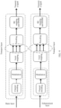
- FIG. 9 shows a processing process on the network device side before sending the data. Channel coding and modulation may be separately performed on the source data by using the basic layer and the enhancement layer.
- the source data may be mapped to one or more transport layers (three transport layers are used as an example in the figure) corresponding to the source data through layer mapping, and then mapped to an OFDM symbol through precoding and RE. Finally, a signal is transmitted. After corresponding data is transmitted to the terminal device side, the terminal device side performs an inverse operation corresponding to operations on the network device side. Details are not described again. Judgments and filtering are separately performed on transport layers of the basic-layer data and the enhancement-layer data of the terminal device.
- estimated network transmission quality information corresponding to the different transport layers is separately obtained based on the RBGs and current total network transmission quality information of the terminal device, and judgments are separately performed depending whether corresponding estimated network transmission quality information at different transport layers meets a preset threshold.
- first estimated network transmission quality information corresponding to different transport layers is separately obtained based on the RBGs and current first network quality information of the terminal device, and judgments are separately performed depending on whether corresponding first estimated network transmission quality information of different transport layers meets a preset threshold.
- transport layers corresponding to layered data namely, base-layer source data
- the filtering of the transport layers corresponding to the enhancement layer is similar to the filtering of the transport layers corresponding to the basic layer, and details are not described herein again.
- the network device updates a quantity of transport layers and/or a rank of transport layers that are of the terminal device in the second terminal device group and that participate in MU-MIMO pairing.
- the transport layer includes a transport layer corresponding to the basic layer of the source data and/or a transport layer corresponding to the enhancement layer of the source data.
- the network device performs MIMO data communication with the terminal device based on the foregoing three steps.
- that the terminal device accepts management performed by the network device on the data communication manner may be reflected in the MIMO data communication with the network device with reference to the foregoing steps.
- the network device determines policies such as pairing and scheduling for performing MIMO data communication with the terminal device, aiming to maximize the XR experience, thereby effectively improving the XR experience, and ensuring the quantity of XR users satisfied with the XR experience.
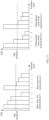
- FIG. 10 shows SNIRs of layers of layered data of the terminal device 0 and the terminal device 1 before pairing.
- MU-MIMO pairing is performed based on a criterion of maximizing a throughput
- three transport layers corresponding to basic-layer source data of the terminal device 0 participate in pairing a system throughput is largest.
- three transport layers, namely, transport layers 1, 2, and 3, corresponding to the basic layer of the terminal device 0 are selected based on the criterion of maximizing the throughput.
- four transport layers corresponding to enhancement-layer source data of the terminal device 0 participate in pairing a system throughput is largest.
- four transport layers namely, transport layers 1, 2, 3, and 4, corresponding to the enhancement layer of the terminal device 0 are selected based on the criterion of maximizing the throughput.
- a system throughput is largest.
- two transport layers, namely, transport layers 1 and 2, corresponding to the basic layer of the terminal device 1 are selected based on the criterion of maximizing the throughput.
- two transport layers corresponding to enhancement-layer source data of the terminal device 1 participate in pairing
- a system throughput is largest.
- two transport layers, namely, transport layers 1 and 2, corresponding to the enhancement layer of the terminal device 1 are selected based on the criterion of maximizing the throughput.
- FIG. 11 shows estimated network transmission quality information of each layer of the layered data of the terminal device 0 and the terminal device 1 before pairing.
- an XQI is used as an example, and MU-MIMO pairing is performed in the manner in this embodiment of this application.
- a quantity of terminal devices satisfied with XQI experience in the system is largest, the basic layer and the enhancement layer of the terminal device 0 respectively meet a layered XR experience requirement (for example, a requirement that the XQI is higher than a preset threshold), and resources (for example, time-frequency resources and/or space domain resources) that can participate in MU-MIMO pairing is largest.
- a layered XR experience requirement for example, a requirement that the XQI is higher than a preset threshold
- resources for example, time-frequency resources and/or space domain resources
- three transport layers corresponding to the base-layer source data namely, transport layers 1, 2, and 3 corresponding to the base-layer source data, of the terminal device 0 are selected, and two transport layers corresponding to the enhancement-layer source data, namely, transport layers 1 and 2 corresponding to the enhancement layer, of the terminal device 0 are selected.
- a quantity of terminal devices satisfied with XR experience in the system is largest, the basic layer and the enhancement layer of the terminal device 1 respectively meet a layered XR experience requirement (for example, a requirement that the XQI is higher than a preset threshold), and resources (for example, time-frequency resources and/or space domain resources) that can participate in MU-MIMO pairing is largest.
- a layered XR experience requirement for example, a requirement that the XQI is higher than a preset threshold
- resources for example, time-frequency resources and/or space domain resources
- one transport layer corresponding to the base-layer source data namely, transport layer 1 corresponding to the base-layer source data
- one transport layer corresponding to the enhancement layer source data namely, transport layer 1 corresponding to the enhancement-layer source data, of the terminal device 1 is selected.
- This embodiment may be combined with any one of the foregoing embodiments and all content in the communication method in FIG. 5 .
- the network device manages a data communication manner, where the data communication manner may include a manner of determining an MCS and/or a resource scheduling of data communication.
- Step 502 includes: The network device determines an initial MCS index of the data communication based on the network transmission quality information and the CSI, adjusts the MCS index of the data communication, and/or determines a resource scheduling priority of the data communication.
- the data communication includes at least XR data communication.
- the network device may determine an initial MCS index of data communication, a scheduling priority of an initially allocated resource, and/or an initially allocated scheduling resource based on the network transmission quality information and the CSI (optionally, further based on at least one of a preset network transmission quality threshold and a BLER target).
- the network device may adjust the MCS index of data communication based on currently obtained network transmission quality information.
- the preset network transmission quality information threshold is 3, an XR experience value included in (corresponding to) the currently obtained network transmission quality information is 2.5, the current MCS index of data communication is 20, and an MCS index indicated in a CSI feedback obtained by the network device is 25.
- the network device should perform index reduction on the MCS of data communication, and preferentially consider a terminal device corresponding to the data communication during resource allocation, because XR experience corresponding to the terminal device is poor and does not meet a threshold.
- the preset network transmission quality threshold is 3, an XR experience value included in (corresponding to) the currently obtained network transmission quality information is 4.5, the current MCS index of data communication is 20, and an MCS index indicated in a CSI feedback obtained by the network device is 25.
- the network device may consider the MCS indicated in the CSI feedback to perform index raising on the current MCS of data communication.
- the network device determines or adjusts, based on the foregoing principle, the MCS index and/or the resource scheduling priority for performing data communication with the terminal device.
- the terminal device accepts management performed by the network device on the data communication manner may be reflected in the data communication with the network device with reference to the foregoing content.
- the network device determines the MCS and/or resource scheduling manner of data communication, aiming to maximize the XR experience, thereby effectively improving the XR experience, and ensuring the quantity of XR users satisfied with the XR experience.
- Embodiment 3 a scenario in which source data transmitted from an application layer is layered is not considered.
- this scenario and related content of the total network transmission quality information, the first network transmission quality information, and the second network transmission quality information derived from this scenario refer to the descriptions in Embodiment 2. Details are not described in this embodiment.
- This embodiment may be combined with, or may include content of any one of the foregoing embodiments and all content in the communication method in FIG. 5 .
- CSI may be correspondingly adjusted.
- the CSI may be divided into first CSI corresponding to the basic layer and second CSI corresponding to the enhancement layer, and the terminal device may separately feed back the first CSI and the second CSI.
- step 502 includes:
- the network device may determine an initial MCS index of data communication of the basic layer, a scheduling priority of an initially allocated resource of the basic layer, and/or an initially allocated scheduling resource of the basic layer based on the first network transmission quality information and the first CSI, and optionally, further based on at least one of a preset network transmission quality threshold and a BLER target.
- the network device may further determine an initial MCS index of data communication of the enhancement layer, a scheduling priority of an initially allocated resource of the enhancement layer, and/or an initially allocated scheduling resource of the enhancement layer based on the second network transmission quality information and the second CSI, and optionally, further based on at least one of the preset network transmission quality threshold and the BLER target.
- the network device may separately adjust the MCS index of layered data communication based on the currently obtained first network transmission quality information and second network transmission quality information.
- a first network transmission quality information threshold preset at the basic layer is 2.5
- a second network transmission quality information threshold preset at the enhancement layer is 1
- an XR experience value included in (corresponding to) the currently obtained first network transmission quality information is 1.5
- an XR experience value included in (corresponding to) the currently obtained second network transmission quality information is 1.2
- a current MCS index of data communication at the basic layer is 20, and an MCS index indicated in a first CSI feedback obtained by the network device is 25.
- the network device should perform index reduction on the MCS of data communication at the basic layer based on the current obtained first network transmission quality information, and preferentially consider the data communication at the basic layer during resource allocation.
- processing on the enhancement layer by the network device may be performed with reference to an MCS index indicated in a second CSI feedback. For example, if the MCS index of data communication at the enhancement layer is 20, and the MCS index indicated in the second CSI feedback is 25, the network device performs index raising on the MCS of data communication at the enhancement layer (for example, raises to 25).
- a first network transmission quality information threshold preset at the basic layer is 2.5
- a second network transmission quality information threshold preset at the enhancement layer is 1
- an XR experience value included in (corresponding to) the currently obtained first network transmission quality information is 3
- an XR experience value included in (corresponding to) the currently obtained second network transmission quality information is 0.5
- a current MCS index of data communication at the basic layer is 20
- an MCS index indicated in a first CSI feedback obtained by the network device is 25
- an MCS index indicated in a second CSI feedback obtained by the network device is 25.
- the network device may perform index raising on the MCS of data communication at the basic layer with reference to the MCS index indicated in the first CSI feedback, and perform index reduction on the MCS of data communication at the enhancement layer based on the current obtained first network transmission quality information.
- the network device may allocate scheduling resources to the enhancement layer to a maximum extent on a basis of ensuring data communication at the basic layer.
- the network device determines or adjusts, based on the foregoing principle, the MCS indexes and/or the resource scheduling priorities of the basic layer and the enhancement layer for performing data communication with the terminal device.
- the terminal device accepts management performed by the network device on the data communication manner may be reflected in the data communication with the network device with reference to the foregoing content.
- the network device determines the MCS and/or resource scheduling manner of layered data communication, aiming to maximize the XR experience, thereby effectively improving the XR experience, and ensuring the quantity of XR users satisfied with the XR experience.
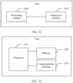
- an embodiment of this application further provides an apparatus 1200.
- the apparatus 1200 includes a transceiver module 1201 and a processing module 1202.
- the apparatus 1200 is configured to implement functions of the network device in the foregoing methods.
- the apparatus may be a network device, or may be an apparatus in the network device.
- the apparatus may be a chip system.
- the chip system may include a chip, or may include a chip and another discrete component.
- the transceiver module 1201 is configured to obtain network transmission quality information and channel state information CSI, where the network transmission quality information indicates communication quality of XR data during network transmission.
- the processing module 1202 is configured to manage a data communication manner based on the network transmission quality information and the CSI.
- Division into the modules in this embodiment of this application is an example of division into logical functions, or may be other division during actual implementation.
- functional modules in embodiments of this application may be integrated into one processor, or each of the modules may exist alone physically, or two or more modules may be integrated into one module.
- the integrated module may be implemented in a form of hardware, or may be implemented in a form of a software functional module.
- the apparatus 1200 is configured to implement functions of the terminal device in the foregoing methods.
- the apparatus may be a terminal device, or may be an apparatus in the terminal device.
- the apparatus may be a chip system.
- the chip system may include a chip, or may include a chip and another discrete component.
- the transceiver module 1201 is configured to send channel state information CSI to a network device.
- the processing module 1202 is configured to accept management performed by the network device on a data communication manner, where the data communication manner is determined based on the CSI and network transmission quality information, and the network transmission quality information indicates communication quality of XR data during network transmission.
- Division into the modules in this embodiment of this application is an example of division into logical functions, or may be other division during actual implementation.
- functional modules in embodiments of this application may be integrated into one processor, or each of the modules may exist alone physically, or two or more modules may be integrated into one module.
- the integrated module may be implemented in a form of hardware, or may be implemented in a form of a software functional module.
- an embodiment of this application further provides an apparatus 1300.
- the apparatus 1300 is configured to implement functions of the terminal device in the foregoing methods.
- the apparatus may be a terminal device, or may be an apparatus in the terminal device.
- the apparatus 1300 includes at least one processor 1301, configured to implement the functions of the terminal device in the foregoing methods.
- the processor 1301 may accept management performed by the network device on a data communication manner.
- the data communication manner is determined based on the CSI and network transmission quality information, and the network transmission quality information indicates communication quality of XR data during network transmission.
- the apparatus 1300 may further include at least one memory 1302, configured to store program instructions and/or data.
- the memory 1302 is coupled to the processor 1301.
- Coupling in this embodiment of this application is indirect coupling or a communication connection between apparatuses, units, or modules, may be in an electrical form, a mechanical form, or another form, and is used for information exchange between apparatuses, units, or modules.
- the memory 1302 may alternatively be located outside the apparatus 1300.
- the processor 1301 may operate in collaboration with the memory 1302.
- the processor 1301 may execute program instructions stored in the memory 1302. At least one of the at least one memory may be included in the processor.
- the apparatus 1300 may further include a communication interface 1303, configured to communicate with another device through a transmission medium, so that an apparatus in the apparatus 1300 can communicate with the another device.
- the communication interface 1303 may be a transceiver, a circuit, a bus, a module, or another type of communication interface, and the another device may be a network device.
- the processor 1301 receives and sends data through the communication interface 1303, and is configured to implement the methods in the foregoing embodiments.
- the communication interface 1303 may send CSI to the network device.
- the apparatus 1300 is configured to implement functions of the network device in the foregoing methods.
- the apparatus may be a network device, or may be an apparatus in the network device.
- the apparatus 1300 includes at least one processor 1301, configured to implement the functions of the network device in the foregoing methods.
- the processor 1301 may obtain network transmission quality information and channel state information CSI, where the network transmission quality information indicates communication quality of XR data during network transmission; and may manage a data communication manner based on the network transmission quality information and the CSI.
- the apparatus 1300 may further include at least one memory 1302, configured to store program instructions and/or data.
- the memory 1302 is coupled to the processor 1301.
- Coupling in this embodiment of this application is indirect coupling or a communication connection between apparatuses, units, or modules, may be in an electrical form, a mechanical form, or another form, and is used for information exchange between apparatuses, units, or modules.
- the memory 1302 may alternatively be located outside the apparatus 1300.
- the processor 1301 may operate in collaboration with the memory 1302.
- the processor 1301 may execute program instructions stored in the memory 1302. At least one of the at least one memory may be included in the processor.
- the apparatus 1300 may further include a communication interface 1303, configured to communicate with another device through a transmission medium, so that an apparatus in the apparatus 1300 can communicate with the another device.
- the communication interface 1303 may be a transceiver, a circuit, a bus, a module, or another type of communication interface, and the another device may be a terminal device or a core network device.
- the processor 1301 receives and sends data through the communication interface 1303, and is configured to implement the methods in the foregoing embodiments.
- the communication interface 1303 may receive the CSI and the network transmission quality information.
- a connection medium between the communication interface 1303, the processor 1301, and the memory 1302 is not limited in this embodiment of this application.
- the processor may be a general-purpose processor, a digital signal processor, an application-specific integrated circuit, a field programmable gate array or another programmable logic device, a discrete gate or transistor logic device, or a discrete hardware component, and may implement or execute the methods, steps, and logical block diagrams disclosed in embodiments of this application.
- the general-purpose processor may be a microprocessor, any conventional processor, or the like. The steps of the method disclosed with reference to this embodiment of this application may be directly performed and completed by a hardware processor, or may be performed and completed by a combination of hardware and software modules in the processor.
- the memory may be a non-volatile memory, such as a hard disk drive (hard disk drive, HDD) or a solid-state drive (solid-state drive, SSD), or may be a volatile memory (volatile memory), such as a random access memory (random access memory, RAM).
- the memory is any other medium that can carry or store expected program code in a form of an instruction structure or a data structure and that can be accessed by a computer, but is not limited thereto.
- the memory in this embodiment of this application may alternatively be a circuit or any other apparatus that can implement a storage function, and is configured to store program instructions and/or data.
- All or some of the methods in embodiments of this application may be implemented through software, hardware, firmware, or any combination thereof.
- software is used to implement the embodiments, all or a part of the embodiments may be implemented in a form of a computer program product.
- the computer program product includes one or more computer instructions.
- the computer may be a general-purpose computer, a dedicated computer, a computer network, a network device, user equipment, or another programmable apparatus.
- the computer instructions may be stored in a computer-readable storage medium or may be transmitted from a computer-readable storage medium to another computer-readable storage medium.
- the computer instructions may be transmitted from a website, computer, server, or data center to another website, computer, server, or data center in a wired (for example, a coaxial cable, an optical fiber, or a digital subscriber line (digital subscriber line, DSL for short)) or wireless (for example, infrared, radio, or microwave) manner.
- the computer-readable storage medium may be any usable medium accessible by a computer, or a data storage device, such as a server or a data center, integrating one or more usable media.
- the usable medium may be a magnetic medium (for example, a floppy disk, a hard disk, or a magnetic tape), an optical medium (for example, a digital video disc (digital video disc, DVD for short)), a semiconductor medium (for example, an SSD), or the like.
- a magnetic medium for example, a floppy disk, a hard disk, or a magnetic tape
- an optical medium for example, a digital video disc (digital video disc, DVD for short)
- a semiconductor medium for example, an SSD
Landscapes
- Engineering & Computer Science (AREA)
- Computer Networks & Wireless Communication (AREA)
- Signal Processing (AREA)
- Quality & Reliability (AREA)
- Artificial Intelligence (AREA)
- Physics & Mathematics (AREA)
- Probability & Statistics with Applications (AREA)
- Mobile Radio Communication Systems (AREA)
Claims (10)
- Kommunikationsverfahren, umfassend:Erhalten von Netzwerkübertragungsqualitätsinformationen und Kanalstatusinformationen, CSI, wobei die Netzwerkübertragungsqualitätsinformationen einen Erweiterte-Realität-, XR, Erfahrungswert umfassen, der eine Kommunikationsqualität von XR-Daten während einer Netzwerkübertragung anzeigt; undVerwalten einer Datenkommunikationsart basierend auf den Netzwerkübertragungsqualitätsinformationen und den CSI,wobei die Datenkommunikationsart eine Datenkommunikationsart umfasst, die auf Mehrfacheingabe-Mehrfachausgabe, MIMO, basiert,wobei das Verwalten einer Datenkommunikationsart insbesondere umfasst:Bestimmen einer Endgerätepaarung, die auf Mehrbenutzer-Mehrfacheingabe-Mehrfachausgabe, MU-MIMO, basiert, und Bestimmen einer Endgeräteplanungssequenz, die auf Einzelbenutzer-Mehrfacheingabe-Mehrfachausgabe, SU-MIMO, basiert,wobei das Verfahren dadurch gekennzeichnet ist, dass es insbesondere umfasst:Bestimmen, basierend auf den CSI, einer ersten Endgerätegruppe, die eine MU-MIMO-Paarungsbedingung erfüllt, und Filtern von Endgeräten in der ersten Endgerätegruppe basierend auf den Netzwerkübertragungsqualitätsinformationen, um eine zweite Endgerätegruppe zu erhalten, die an einer MU-MIMO-Paarung teilnimmt, wobei das Filtern Einstellen eines Schwellenwerts für die Netzwerkübertragungsqualitätsinformationen und nur dann Zulassen, dass ein Endgerät an der MU-MIMO-Paarung teilnimmt, wenn die dem Endgerät entsprechenden Netzwerkübertragungsqualitätsinformationen den Schwellenwert erfüllen, umfasst;Erhalten, basierend auf den Netzwerkübertragungsqualitätsinformationen, einer Planungssequenz, die auf SU-MIMO basiert, für Endgeräte in der zweiten Endgerätegruppe, undFiltern von Transportschichten der Endgeräte in der zweiten Endgerätegruppe basierend auf der Planungssequenz, die auf SU-MIMO basiert, und den Netzwerkübertragungsqualitätsinformationen, um Transportschichten zu erhalten, die zu den Endgeräten in der zweiten Endgerätegruppe gehören und die an einer MU-MIMO-Paarung teilnehmen.
- Verfahren nach Anspruch 1, wobei der Datenkommunikation entsprechende Quelldaten in Quelldaten einer Basisschicht und Quelldaten einer Erweiterungsschicht unterteilt werden, und die Netzwerkübertragungsqualitätsinformationen erste Netzwerkübertragungsqualitätsinformationen, die der Basisschicht entsprechen, zweite Netzwerkübertragungsqualitätsinformationen, die der Erweiterungsschicht entsprechen, und Netzwerkübertragungsqualitäts-Gesamtinformationen umfassen.
- Kommunikationsverfahren, umfassend:Senden, durch ein Endgerät, von Kanalstatusinformationen, CSI, an ein Netzwerkgerät,Erhalten von Netzwerkübertragungsqualitätsinformationen undKanalstatusinformationen, CSI, durch das Netzwerkgerät, wobei die Netzwerkübertragungsqualitätsinformationen einen Erweiterte-Realität-, XR,Erfahrungswert umfassen, der eine Kommunikationsqualität von XR-Daten während einer Netzwerkübertragung anzeigt;Verwalten, durch das Netzwerkgerät, einer Datenkommunikationsart basierend auf den Netzwerkübertragungsqualitätsinformationen und den CSI, undAnnehmen, durch das Endgerät, einer durch das Netzwerkgerät an einer Datenkommunikationsart durchgeführten Verwaltung, wobei die Datenkommunikationsart basierend auf den CSI und den Netzwerkübertragungsqualitätsinformationen bestimmt wird, und die Netzwerkübertragungsqualitätsinformationen eine Kommunikationsqualität von Erweiterte-Realität-, XR, Daten während einer Netzwerkübertragung anzeigen;wobei die Datenkommunikationsart eine Datenkommunikationsart umfasst, die auf Mehrfacheingabe-Mehrfachausgabe, MIMO, basiert,wobei das Verwalten einer Datenkommunikationsart insbesondere umfasst:Bestimmen einer Sendegerätepaarung, die auf Mehrbenutzer-Mehrfacheingabe-Mehrfachausgabe, MU-MIMO, basiert, und Bestimmen einer Sendegeräteplanungssequenz, die auf Einzelbenutzer-Mehrfacheingabe-Mehrfachausgabe, SU-MIMO, basiert,wobei das Verfahren dadurch gekennzeichnet ist, dass es insbesondere umfasst:Bestimmen, durch das Netzwerkgerät, basierend auf den CSI, einer ersten Endgerätegruppe, die eine MU-MIMO-Paarungsbedingung erfüllt, und Filtern von Endgeräten in der ersten Endgerätegruppe basierend auf den Netzwerkübertragungsqualitätsinformationen, um eine zweite Endgerätegruppe zu erhalten, die an einer MU-MIMO-Paarung teilnimmt, wobei das Filtern Einstellen eines Schwellenwerts für die Netzwerkübertragungsqualitätsinformationen und nur dann Zulassen, dass ein Endgerät an der MU-MIMO-Paarung teilnimmt, wenn die dem Endgerät entsprechenden Netzwerkübertragungsqualitätsinformationen den Schwellenwert erfüllen, umfasst;Erhalten, durch die Netzwerkvorrichtung, basierend auf den Netzwerkübertragungsqualitätsinformationen, einer Planungssequenz, die auf SU-MIMO basiert, für Endgeräte in der zweiten Endgerätegruppe, undFiltern, durch die Netzwerkvorrichtung, von Transportschichten der Endgeräte in der zweiten Endgerätegruppe basierend auf der Planungssequenz, die auf SU-MIMO basiert, und den Netzwerkübertragungsqualitätsinformationen, um Transportschichten zu erhalten, die zu den Endgeräten in der zweiten Endgerätegruppe gehören und die an einer MU-MIMO-Paarung teilnehmen.
- Verfahren nach Anspruch 3, wobei das Verfahren ferner umfasst:
Senden der Netzwerkübertragungsqualitätsinformationen an das Netzwerkgerät. - Verfahren nach Anspruch 3 oder 4, wobei, dass das Annehmen einer durch das Netzwerkgerät an einer Datenkommunikationsart durchgeführten Verwaltung ein Annehmen einer durch das Netzwerkgerät an der Datenkommunikationsart durchgeführten Verwaltung, die auf MIMO basiert, ist, insbesondere umfasst: Annehmen von Paarungsinformationen, die auf Mehrbenutzer-Mehrfacheingabe-Mehrfachausgabe, MU-MIMO, basieren, und Planungssequenzinformationen, die auf Einzelbenutzer-Mehrfacheingabe-Mehrfachausgabe, SU-MIMO, basieren.
- Verfahren nach Anspruch 3 oder 4, wobei die Datenkommunikationsart umfasst: ein Modulations- und Codierungsschema, MCS, und/oder eine Ressourcenplanungsart einer Datenkommunikation.
- Kommunikationsvorrichtung (1200), die Einheiten umfasst, die dazu konfiguriert sind, das Verfahren nach einem der Ansprüche 1 oder 2 zu implementieren.
- Computerlesbares Speichermedium, wobei das computerlesbare Speichermedium Anweisungen speichert, und wenn die Anweisungen auf einem Computer ausgeführt werden, die Anweisungen den Computer veranlassen, das Verfahren nach einem der Ansprüche 1 bis 2 durchzuführen.
- Computerprogrammprodukt, das Anweisungen umfasst, die, wenn sie durch einen Computer ausgeführt werden, den Computer veranlassen, das Verfahren nach einem der Ansprüche 1 bis 2 durchzuführen.
- Chip, der einen Prozessor (1301) umfasst, wobei der Prozessor (1301) mit einem Speicher (1302) gekoppelt ist, wobei der Speicher (1302) dazu konfiguriert ist, ein Programm oder Anweisungen zu speichern; und wobei, wenn das Programm oder die Anweisungen durch den Prozessor (1301) ausgeführt werden, das Programm oder die Anweisungen den Prozessor veranlassen, das Verfahren nach den Ansprüchen 1 oder 2 durchzuführen.
Applications Claiming Priority (2)
| Application Number | Priority Date | Filing Date | Title |
|---|---|---|---|
| CN202010531821.3A CN113810089B (zh) | 2020-06-11 | 2020-06-11 | 一种通信方法及装置 |
| PCT/CN2021/098163 WO2021249280A1 (zh) | 2020-06-11 | 2021-06-03 | 一种通信方法及装置 |
Publications (3)
| Publication Number | Publication Date |
|---|---|
| EP4149013A1 EP4149013A1 (de) | 2023-03-15 |
| EP4149013A4 EP4149013A4 (de) | 2023-10-18 |
| EP4149013B1 true EP4149013B1 (de) | 2024-07-31 |
Family
ID=78845271
Family Applications (1)
| Application Number | Title | Priority Date | Filing Date |
|---|---|---|---|
| EP21822865.8A Active EP4149013B1 (de) | 2020-06-11 | 2021-06-03 | Kommunikationsverfahren und -vorrichtung |
Country Status (4)
| Country | Link |
|---|---|
| US (1) | US20230108591A1 (de) |
| EP (1) | EP4149013B1 (de) |
| CN (1) | CN113810089B (de) |
| WO (1) | WO2021249280A1 (de) |
Families Citing this family (4)
| Publication number | Priority date | Publication date | Assignee | Title |
|---|---|---|---|---|
| EP4297509A4 (de) * | 2021-06-04 | 2024-08-28 | Samsung Electronics Co., Ltd. | Elektronische vorrichtung zur ressourcenzuweisung in einem wlan-system und betriebsverfahren dafür |
| EP4136871B1 (de) * | 2021-06-27 | 2025-06-18 | Apple Inc. | Sidelink-rückkopplungsverbesserung |
| CN113677003B (zh) * | 2021-08-10 | 2022-05-31 | 上海移远通信技术股份有限公司 | 无线通信方法、装置、设备及存储介质 |
| US20230379955A1 (en) * | 2022-05-18 | 2023-11-23 | Bank Of America Corporation | System for intelligent data channel selection and dynamic switching |
Family Cites Families (11)
| Publication number | Priority date | Publication date | Assignee | Title |
|---|---|---|---|---|
| US9332455B2 (en) * | 2012-10-15 | 2016-05-03 | Headwater Partners Ii Llc | Scheduling a user equipment transmission mode to assist uplink interference characterization |
| US10084581B2 (en) * | 2014-07-11 | 2018-09-25 | Qualcomm Incorporated | Overlay unicast or MBSFN data transmission on top of MBSFN transmission |
| CN107733491A (zh) * | 2016-08-09 | 2018-02-23 | 北京信威通信技术股份有限公司 | 一种下行多用户多天线传输的方法及装置 |
| US10397032B2 (en) * | 2016-08-22 | 2019-08-27 | Qualcomm Incorporated | Energy determinations for multi-user superposition transmissions |
| WO2018082672A1 (zh) * | 2016-11-04 | 2018-05-11 | 华为技术有限公司 | 一种上行测量参考信号传输方法、装置和系统 |
| US10462801B2 (en) * | 2017-05-05 | 2019-10-29 | At&T Intellectual Property I, L.P. | Multi-antenna transmission protocols for high doppler conditions |
| CN116032447A (zh) * | 2017-06-14 | 2023-04-28 | Idac控股公司 | 可靠控制信令 |
| CN112803980B (zh) * | 2017-11-17 | 2022-09-02 | 华为技术有限公司 | 用于无线网络中信道测量和干扰测量的系统和方法 |
| CN108965949B (zh) * | 2018-07-27 | 2020-06-16 | 清华大学 | 一种视频业务中满足用户个性化体验的码率自适应方法 |
| US10833742B2 (en) * | 2018-08-10 | 2020-11-10 | At&T Intellectual Property I, L.P. | Determining channel state information in advanced networks |
| KR102614495B1 (ko) * | 2019-08-02 | 2023-12-15 | 엘지전자 주식회사 | Xr 디바이스 및 그 제어 방법 |
-
2020
- 2020-06-11 CN CN202010531821.3A patent/CN113810089B/zh active Active
-
2021
- 2021-06-03 EP EP21822865.8A patent/EP4149013B1/de active Active
- 2021-06-03 WO PCT/CN2021/098163 patent/WO2021249280A1/zh not_active Ceased
-
2022
- 2022-12-12 US US18/079,273 patent/US20230108591A1/en active Pending
Also Published As
| Publication number | Publication date |
|---|---|
| US20230108591A1 (en) | 2023-04-06 |
| EP4149013A4 (de) | 2023-10-18 |
| CN113810089A (zh) | 2021-12-17 |
| WO2021249280A1 (zh) | 2021-12-16 |
| CN113810089B (zh) | 2023-09-29 |
| EP4149013A1 (de) | 2023-03-15 |
Similar Documents
| Publication | Publication Date | Title |
|---|---|---|
| EP4149013B1 (de) | Kommunikationsverfahren und -vorrichtung | |
| KR102316008B1 (ko) | 5g 또는 다른 차세대 네트워크를 위한 피드백 데이터를 송신하기 위한 반복 인수들의 구성 | |
| US12057902B2 (en) | Method and device of communication in a communication system using an open radio access network | |
| US12063111B2 (en) | Enhancing the robustness of uplink transmission | |
| US12192264B2 (en) | Network-based adaptive streaming media parameter adjustment method and an apparatus | |
| US10979121B2 (en) | Channel state information determination using demodulation reference signals in advanced networks | |
| US11277179B2 (en) | Determining channel state information in advanced networks | |
| US20220231747A1 (en) | Facilitation of beam failure indication for multiple transmission points for 5g or other next generation network | |
| US12088418B2 (en) | Hybrid automatic repeat request feedback for outer loop adaptation for 5G or other next generation network | |
| US11576197B2 (en) | Facilitating improved performance of multiple downlink control channels in advanced networks | |
| EP2947939B1 (de) | Verfahren und vorrichtung zur ressourcenplanung in einer koordinierten mehrpunktübertragung | |
| CN118556441A (zh) | 用于蜂窝网络的时分双工模式配置 | |
| US20200015141A1 (en) | Beam avoidance method and base station | |
| Gupta et al. | Unlocking wireless performance with co-operation in co-located base station pools | |
| US20240340680A1 (en) | Selective learning for ue reported values | |
| CN102045778A (zh) | 一种基于QoS的多基站自适应协作传输方法 | |
| Ferreira et al. | Resource scheduling scheme for 5G mmWave CP‐OFDM based wireless networks with delay and power allocation optimizations | |
| US12445693B2 (en) | Data transmission method and communication apparatus | |
| US12408082B2 (en) | Reducing network traffic associated with a throughput intensive communication over a wireless telecommunication network | |
| US12407440B2 (en) | Method, apparatus and computer program | |
| WO2024046250A1 (zh) | 一种被用于无线通信的节点中的方法和装置 | |
| CN120835326A (zh) | 一种业务信号的发送方法及相关设备 | |
| WO2024238545A1 (en) | Xr-specific uci encoding and multiplexing procedures | |
| CN120343736A (zh) | 通信方法、装置、终端及网络侧设备 |
Legal Events
| Date | Code | Title | Description |
|---|---|---|---|
| STAA | Information on the status of an ep patent application or granted ep patent |
Free format text: STATUS: THE INTERNATIONAL PUBLICATION HAS BEEN MADE |
|
| PUAI | Public reference made under article 153(3) epc to a published international application that has entered the european phase |
Free format text: ORIGINAL CODE: 0009012 |
|
| STAA | Information on the status of an ep patent application or granted ep patent |
Free format text: STATUS: REQUEST FOR EXAMINATION WAS MADE |
|
| 17P | Request for examination filed |
Effective date: 20221209 |
|
| AK | Designated contracting states |
Kind code of ref document: A1 Designated state(s): AL AT BE BG CH CY CZ DE DK EE ES FI FR GB GR HR HU IE IS IT LI LT LU LV MC MK MT NL NO PL PT RO RS SE SI SK SM TR |
|
| DAV | Request for validation of the european patent (deleted) | ||
| DAX | Request for extension of the european patent (deleted) | ||
| A4 | Supplementary search report drawn up and despatched |
Effective date: 20230918 |
|
| RIC1 | Information provided on ipc code assigned before grant |
Ipc: H04B 7/0452 20170101ALI20230912BHEP Ipc: H04L 1/00 20060101ALI20230912BHEP Ipc: H04B 7/06 20060101AFI20230912BHEP |
|
| GRAP | Despatch of communication of intention to grant a patent |
Free format text: ORIGINAL CODE: EPIDOSNIGR1 |
|
| STAA | Information on the status of an ep patent application or granted ep patent |
Free format text: STATUS: GRANT OF PATENT IS INTENDED |
|
| INTG | Intention to grant announced |
Effective date: 20240327 |
|
| GRAS | Grant fee paid |
Free format text: ORIGINAL CODE: EPIDOSNIGR3 |
|
| GRAA | (expected) grant |
Free format text: ORIGINAL CODE: 0009210 |
|
| STAA | Information on the status of an ep patent application or granted ep patent |
Free format text: STATUS: THE PATENT HAS BEEN GRANTED |
|
| AK | Designated contracting states |
Kind code of ref document: B1 Designated state(s): AL AT BE BG CH CY CZ DE DK EE ES FI FR GB GR HR HU IE IS IT LI LT LU LV MC MK MT NL NO PL PT RO RS SE SI SK SM TR |
|
| REG | Reference to a national code |
Ref country code: CH Ref legal event code: EP Ref country code: GB Ref legal event code: FG4D |
|
| REG | Reference to a national code |
Ref country code: DE Ref legal event code: R096 Ref document number: 602021016592 Country of ref document: DE |
|
| REG | Reference to a national code |
Ref country code: IE Ref legal event code: FG4D |
|
| REG | Reference to a national code |
Ref country code: LT Ref legal event code: MG9D |
|
| REG | Reference to a national code |
Ref country code: NL Ref legal event code: MP Effective date: 20240731 |
|
| PG25 | Lapsed in a contracting state [announced via postgrant information from national office to epo] |
Ref country code: PT Free format text: LAPSE BECAUSE OF FAILURE TO SUBMIT A TRANSLATION OF THE DESCRIPTION OR TO PAY THE FEE WITHIN THE PRESCRIBED TIME-LIMIT Effective date: 20241202 |
|
| REG | Reference to a national code |
Ref country code: AT Ref legal event code: MK05 Ref document number: 1709487 Country of ref document: AT Kind code of ref document: T Effective date: 20240731 |
|
| PG25 | Lapsed in a contracting state [announced via postgrant information from national office to epo] |
Ref country code: PT Free format text: LAPSE BECAUSE OF FAILURE TO SUBMIT A TRANSLATION OF THE DESCRIPTION OR TO PAY THE FEE WITHIN THE PRESCRIBED TIME-LIMIT Effective date: 20241202 |
|
| PG25 | Lapsed in a contracting state [announced via postgrant information from national office to epo] |
Ref country code: NO Free format text: LAPSE BECAUSE OF FAILURE TO SUBMIT A TRANSLATION OF THE DESCRIPTION OR TO PAY THE FEE WITHIN THE PRESCRIBED TIME-LIMIT Effective date: 20241031 |
|
| PG25 | Lapsed in a contracting state [announced via postgrant information from national office to epo] |
Ref country code: NL Free format text: LAPSE BECAUSE OF FAILURE TO SUBMIT A TRANSLATION OF THE DESCRIPTION OR TO PAY THE FEE WITHIN THE PRESCRIBED TIME-LIMIT Effective date: 20240731 Ref country code: FI Free format text: LAPSE BECAUSE OF FAILURE TO SUBMIT A TRANSLATION OF THE DESCRIPTION OR TO PAY THE FEE WITHIN THE PRESCRIBED TIME-LIMIT Effective date: 20240731 Ref country code: PL Free format text: LAPSE BECAUSE OF FAILURE TO SUBMIT A TRANSLATION OF THE DESCRIPTION OR TO PAY THE FEE WITHIN THE PRESCRIBED TIME-LIMIT Effective date: 20240731 Ref country code: GR Free format text: LAPSE BECAUSE OF FAILURE TO SUBMIT A TRANSLATION OF THE DESCRIPTION OR TO PAY THE FEE WITHIN THE PRESCRIBED TIME-LIMIT Effective date: 20241101 |
|
| PG25 | Lapsed in a contracting state [announced via postgrant information from national office to epo] |
Ref country code: BG Free format text: LAPSE BECAUSE OF FAILURE TO SUBMIT A TRANSLATION OF THE DESCRIPTION OR TO PAY THE FEE WITHIN THE PRESCRIBED TIME-LIMIT Effective date: 20240731 |
|
| PG25 | Lapsed in a contracting state [announced via postgrant information from national office to epo] |
Ref country code: LV Free format text: LAPSE BECAUSE OF FAILURE TO SUBMIT A TRANSLATION OF THE DESCRIPTION OR TO PAY THE FEE WITHIN THE PRESCRIBED TIME-LIMIT Effective date: 20240731 |
|
| PG25 | Lapsed in a contracting state [announced via postgrant information from national office to epo] |
Ref country code: IS Free format text: LAPSE BECAUSE OF FAILURE TO SUBMIT A TRANSLATION OF THE DESCRIPTION OR TO PAY THE FEE WITHIN THE PRESCRIBED TIME-LIMIT Effective date: 20241130 Ref country code: AT Free format text: LAPSE BECAUSE OF FAILURE TO SUBMIT A TRANSLATION OF THE DESCRIPTION OR TO PAY THE FEE WITHIN THE PRESCRIBED TIME-LIMIT Effective date: 20240731 |
|
| PG25 | Lapsed in a contracting state [announced via postgrant information from national office to epo] |
Ref country code: HR Free format text: LAPSE BECAUSE OF FAILURE TO SUBMIT A TRANSLATION OF THE DESCRIPTION OR TO PAY THE FEE WITHIN THE PRESCRIBED TIME-LIMIT Effective date: 20240731 |
|
| PG25 | Lapsed in a contracting state [announced via postgrant information from national office to epo] |
Ref country code: ES Free format text: LAPSE BECAUSE OF FAILURE TO SUBMIT A TRANSLATION OF THE DESCRIPTION OR TO PAY THE FEE WITHIN THE PRESCRIBED TIME-LIMIT Effective date: 20240731 Ref country code: RS Free format text: LAPSE BECAUSE OF FAILURE TO SUBMIT A TRANSLATION OF THE DESCRIPTION OR TO PAY THE FEE WITHIN THE PRESCRIBED TIME-LIMIT Effective date: 20241031 |
|
| PG25 | Lapsed in a contracting state [announced via postgrant information from national office to epo] |
Ref country code: RS Free format text: LAPSE BECAUSE OF FAILURE TO SUBMIT A TRANSLATION OF THE DESCRIPTION OR TO PAY THE FEE WITHIN THE PRESCRIBED TIME-LIMIT Effective date: 20241031 Ref country code: PL Free format text: LAPSE BECAUSE OF FAILURE TO SUBMIT A TRANSLATION OF THE DESCRIPTION OR TO PAY THE FEE WITHIN THE PRESCRIBED TIME-LIMIT Effective date: 20240731 Ref country code: NO Free format text: LAPSE BECAUSE OF FAILURE TO SUBMIT A TRANSLATION OF THE DESCRIPTION OR TO PAY THE FEE WITHIN THE PRESCRIBED TIME-LIMIT Effective date: 20241031 Ref country code: NL Free format text: LAPSE BECAUSE OF FAILURE TO SUBMIT A TRANSLATION OF THE DESCRIPTION OR TO PAY THE FEE WITHIN THE PRESCRIBED TIME-LIMIT Effective date: 20240731 Ref country code: LV Free format text: LAPSE BECAUSE OF FAILURE TO SUBMIT A TRANSLATION OF THE DESCRIPTION OR TO PAY THE FEE WITHIN THE PRESCRIBED TIME-LIMIT Effective date: 20240731 Ref country code: IS Free format text: LAPSE BECAUSE OF FAILURE TO SUBMIT A TRANSLATION OF THE DESCRIPTION OR TO PAY THE FEE WITHIN THE PRESCRIBED TIME-LIMIT Effective date: 20241130 Ref country code: HR Free format text: LAPSE BECAUSE OF FAILURE TO SUBMIT A TRANSLATION OF THE DESCRIPTION OR TO PAY THE FEE WITHIN THE PRESCRIBED TIME-LIMIT Effective date: 20240731 Ref country code: GR Free format text: LAPSE BECAUSE OF FAILURE TO SUBMIT A TRANSLATION OF THE DESCRIPTION OR TO PAY THE FEE WITHIN THE PRESCRIBED TIME-LIMIT Effective date: 20241101 Ref country code: FI Free format text: LAPSE BECAUSE OF FAILURE TO SUBMIT A TRANSLATION OF THE DESCRIPTION OR TO PAY THE FEE WITHIN THE PRESCRIBED TIME-LIMIT Effective date: 20240731 Ref country code: ES Free format text: LAPSE BECAUSE OF FAILURE TO SUBMIT A TRANSLATION OF THE DESCRIPTION OR TO PAY THE FEE WITHIN THE PRESCRIBED TIME-LIMIT Effective date: 20240731 Ref country code: BG Free format text: LAPSE BECAUSE OF FAILURE TO SUBMIT A TRANSLATION OF THE DESCRIPTION OR TO PAY THE FEE WITHIN THE PRESCRIBED TIME-LIMIT Effective date: 20240731 Ref country code: AT Free format text: LAPSE BECAUSE OF FAILURE TO SUBMIT A TRANSLATION OF THE DESCRIPTION OR TO PAY THE FEE WITHIN THE PRESCRIBED TIME-LIMIT Effective date: 20240731 |
|
| PG25 | Lapsed in a contracting state [announced via postgrant information from national office to epo] |
Ref country code: DK Free format text: LAPSE BECAUSE OF FAILURE TO SUBMIT A TRANSLATION OF THE DESCRIPTION OR TO PAY THE FEE WITHIN THE PRESCRIBED TIME-LIMIT Effective date: 20240731 Ref country code: SM Free format text: LAPSE BECAUSE OF FAILURE TO SUBMIT A TRANSLATION OF THE DESCRIPTION OR TO PAY THE FEE WITHIN THE PRESCRIBED TIME-LIMIT Effective date: 20240731 Ref country code: RO Free format text: LAPSE BECAUSE OF FAILURE TO SUBMIT A TRANSLATION OF THE DESCRIPTION OR TO PAY THE FEE WITHIN THE PRESCRIBED TIME-LIMIT Effective date: 20240731 |
|
| PG25 | Lapsed in a contracting state [announced via postgrant information from national office to epo] |
Ref country code: EE Free format text: LAPSE BECAUSE OF FAILURE TO SUBMIT A TRANSLATION OF THE DESCRIPTION OR TO PAY THE FEE WITHIN THE PRESCRIBED TIME-LIMIT Effective date: 20240731 |
|
| PG25 | Lapsed in a contracting state [announced via postgrant information from national office to epo] |
Ref country code: CZ Free format text: LAPSE BECAUSE OF FAILURE TO SUBMIT A TRANSLATION OF THE DESCRIPTION OR TO PAY THE FEE WITHIN THE PRESCRIBED TIME-LIMIT Effective date: 20240731 |
|
| PG25 | Lapsed in a contracting state [announced via postgrant information from national office to epo] |
Ref country code: SK Free format text: LAPSE BECAUSE OF FAILURE TO SUBMIT A TRANSLATION OF THE DESCRIPTION OR TO PAY THE FEE WITHIN THE PRESCRIBED TIME-LIMIT Effective date: 20240731 Ref country code: IT Free format text: LAPSE BECAUSE OF FAILURE TO SUBMIT A TRANSLATION OF THE DESCRIPTION OR TO PAY THE FEE WITHIN THE PRESCRIBED TIME-LIMIT Effective date: 20240731 |
|
| REG | Reference to a national code |
Ref country code: DE Ref legal event code: R097 Ref document number: 602021016592 Country of ref document: DE |
|
| PLBE | No opposition filed within time limit |
Free format text: ORIGINAL CODE: 0009261 |
|
| STAA | Information on the status of an ep patent application or granted ep patent |
Free format text: STATUS: NO OPPOSITION FILED WITHIN TIME LIMIT |
|
| 26N | No opposition filed |
Effective date: 20250501 |
|
| PGFP | Annual fee paid to national office [announced via postgrant information from national office to epo] |
Ref country code: GB Payment date: 20250501 Year of fee payment: 5 |
|
| PG25 | Lapsed in a contracting state [announced via postgrant information from national office to epo] |
Ref country code: SE Free format text: LAPSE BECAUSE OF FAILURE TO SUBMIT A TRANSLATION OF THE DESCRIPTION OR TO PAY THE FEE WITHIN THE PRESCRIBED TIME-LIMIT Effective date: 20240731 |