EP4149010A1 - Strahlausrichtungsverfahren und zugehörige vorrichtung - Google Patents
Strahlausrichtungsverfahren und zugehörige vorrichtung Download PDFInfo
- Publication number
- EP4149010A1 EP4149010A1 EP21817823.4A EP21817823A EP4149010A1 EP 4149010 A1 EP4149010 A1 EP 4149010A1 EP 21817823 A EP21817823 A EP 21817823A EP 4149010 A1 EP4149010 A1 EP 4149010A1
- Authority
- EP
- European Patent Office
- Prior art keywords
- terminal device
- receive
- location
- optimal
- rotation angle
- Prior art date
- Legal status (The legal status is an assumption and is not a legal conclusion. Google has not performed a legal analysis and makes no representation as to the accuracy of the status listed.)
- Pending
Links
Images

Classifications
-
- G—PHYSICS
- G01—MEASURING; TESTING
- G01S—RADIO DIRECTION-FINDING; RADIO NAVIGATION; DETERMINING DISTANCE OR VELOCITY BY USE OF RADIO WAVES; LOCATING OR PRESENCE-DETECTING BY USE OF THE REFLECTION OR RERADIATION OF RADIO WAVES; ANALOGOUS ARRANGEMENTS USING OTHER WAVES
- G01S3/00—Direction-finders for determining the direction from which infrasonic, sonic, ultrasonic or electromagnetic waves, or particle emission, not having a directional significance, are being received
- G01S3/02—Direction-finders for determining the direction from which infrasonic, sonic, ultrasonic or electromagnetic waves, or particle emission, not having a directional significance, are being received using radio waves
- G01S3/04—Details
- G01S3/06—Means for increasing effective directivity, e.g. by combining signals having differently oriented directivity characteristics or by sharpening the envelope waveform of the signal derived from a rotating or oscillating beam antenna
-
- H—ELECTRICITY
- H04—ELECTRIC COMMUNICATION TECHNIQUE
- H04B—TRANSMISSION
- H04B7/00—Radio transmission systems, i.e. using radiation field
- H04B7/02—Diversity systems; Multi-antenna system, i.e. transmission or reception using multiple antennas
- H04B7/04—Diversity systems; Multi-antenna system, i.e. transmission or reception using multiple antennas using two or more spaced independent antennas
- H04B7/0408—Diversity systems; Multi-antenna system, i.e. transmission or reception using multiple antennas using two or more spaced independent antennas using two or more beams, i.e. beam diversity
-
- H—ELECTRICITY
- H04—ELECTRIC COMMUNICATION TECHNIQUE
- H04B—TRANSMISSION
- H04B7/00—Radio transmission systems, i.e. using radiation field
- H04B7/02—Diversity systems; Multi-antenna system, i.e. transmission or reception using multiple antennas
- H04B7/04—Diversity systems; Multi-antenna system, i.e. transmission or reception using multiple antennas using two or more spaced independent antennas
- H04B7/06—Diversity systems; Multi-antenna system, i.e. transmission or reception using multiple antennas using two or more spaced independent antennas at the transmitting station
- H04B7/0613—Diversity systems; Multi-antenna system, i.e. transmission or reception using multiple antennas using two or more spaced independent antennas at the transmitting station using simultaneous transmission
- H04B7/0615—Diversity systems; Multi-antenna system, i.e. transmission or reception using multiple antennas using two or more spaced independent antennas at the transmitting station using simultaneous transmission of weighted versions of same signal
- H04B7/0617—Diversity systems; Multi-antenna system, i.e. transmission or reception using multiple antennas using two or more spaced independent antennas at the transmitting station using simultaneous transmission of weighted versions of same signal for beam forming
-
- H—ELECTRICITY
- H04—ELECTRIC COMMUNICATION TECHNIQUE
- H04B—TRANSMISSION
- H04B7/00—Radio transmission systems, i.e. using radiation field
- H04B7/02—Diversity systems; Multi-antenna system, i.e. transmission or reception using multiple antennas
- H04B7/04—Diversity systems; Multi-antenna system, i.e. transmission or reception using multiple antennas using two or more spaced independent antennas
- H04B7/06—Diversity systems; Multi-antenna system, i.e. transmission or reception using multiple antennas using two or more spaced independent antennas at the transmitting station
- H04B7/0686—Hybrid systems, i.e. switching and simultaneous transmission
- H04B7/0695—Hybrid systems, i.e. switching and simultaneous transmission using beam selection
- H04B7/06952—Selecting one or more beams from a plurality of beams, e.g. beam training, management or sweeping
- H04B7/0696—Determining beam pairs
-
- H—ELECTRICITY
- H04—ELECTRIC COMMUNICATION TECHNIQUE
- H04B—TRANSMISSION
- H04B7/00—Radio transmission systems, i.e. using radiation field
- H04B7/02—Diversity systems; Multi-antenna system, i.e. transmission or reception using multiple antennas
- H04B7/04—Diversity systems; Multi-antenna system, i.e. transmission or reception using multiple antennas using two or more spaced independent antennas
- H04B7/08—Diversity systems; Multi-antenna system, i.e. transmission or reception using multiple antennas using two or more spaced independent antennas at the receiving station
- H04B7/0868—Hybrid systems, i.e. switching and combining
- H04B7/088—Hybrid systems, i.e. switching and combining using beam selection
Definitions
- This application relates to the field of communications technologies, and in particular, to a beam alignment method and a related device.
- a millimeter wave (millimeter wave, mmWave) is one of most potential technologies in promoting development of a 5th generation (5th generation, 5G) mobile communications technology.
- the millimeter wave has features of high bandwidth, a low latency, and an inexpensive spectrum, which can reduce costs for operators. Therefore, in 5G technology development, the mmWave can not only provide a higher data transmission rate, but also reduce transmission costs per bit.
- the mmWave has a short wavelength and a high frequency, has strong attenuation, and is susceptible to rain fade and atmospheric absorption. Therefore, alignment between a receive beam and a transmit beam cannot be ensured, and an optimal receive gain and an optimal transmit gain cannot be obtained.
- Embodiments of this application provide a beam alignment method and a related device, to increase a transmit gain or a receive gain of a terminal device, and improve coverage and mobility of a millimeter wave.
- an embodiment of this application provides a beam alignment method, including: receiving, at a current location by using a plurality of receive beams, a transmit beam sent by a network device, and determining reference signal received power RSRP of each of the plurality of receive beams; selecting an optimal receive beam from the plurality of receive beams based on the RSRP; determining, based on the optimal receive beam, a rotation angle and a rotation direction that are required by a terminal device to align a peak direction beam with the transmit beam; and adjusting a location of the terminal device based on the rotation angle and the rotation direction, and forming an optimal beam pair by using the peak direction beam and the transmit beam at an adjusted location.
- the rotation angle and the rotation direction that are required for rotating from a location of the peak direction beam to a location of the optimal receive beam are determined, so that after adjusting the location, the terminal device can form an optimal beam pair by using the peak direction beam and the transmit beam. This not only increases a transmit gain or a receive gain of the terminal device, but also improves coverage and mobility of a millimeter wave.
- the rotation angle and the rotation direction are displayed. Therefore, a user can adjust the location of the terminal device based on the displayed rotation angle and rotation direction, and the operation is convenient and quick.
- prompt information is displayed.
- the prompt information is used to prompt the user that adjustment of the location of the terminal device is completed. Therefore, when viewing the prompt information, the user can stop rotating the location of the terminal device, to improve accuracy of adjusting the location.
- the terminal device may select, from the plurality of receive beams, a receive beam with highest RSRP as the optimal receive beam.
- the receive beam with highest RSRP is selected as the optimal receive beam, and the rotation angle and the rotation direction that are required for rotating from the location of the peak direction beam to the location of the optimal receive beam are determined, so that the transmit gain or the receive gain of the terminal device is increased to an optimal effect.
- the terminal device may determine a relative location of the peak direction beam and the optimal receive beam; and determine, based on the relative location, the rotation angle and the rotation direction that are required by the terminal device to align the peak direction beam with the transmit beam.
- the rotation angle and the rotation direction that are required for rotating from the location of the peak direction beam to the location of the optimal receive beam are determined by using the relative location of the peak direction beam and the optimal receive beam, to improve accuracy of determining the rotation angle and the rotation direction.
- the peak direction beam is a beam perpendicular to an antenna panel of the network device.
- an embodiment of this application provides a terminal device.
- the terminal device includes a modem, a processor, and a display.
- the modem is configured to: receive, at a current location by using a plurality of receive beams, a transmit beam sent by a network device, determine reference signal received power RSRP of each of the plurality of receive beams, select an optimal receive beam from the plurality of receive beams based on the RSRP, and send the optimal receive beam to the processor.
- the processor is configured to: receive the optimal receive beam, determine a rotation angle and a rotation direction that are required by the terminal device to align a peak direction beam with the transmit beam, adjust a location of the terminal device based on the rotation angle and the rotation direction, and form an optimal beam pair by using the peak direction beam and the transmit beam at an adjusted location.
- the rotation angle and the rotation direction that are required for rotating from a location of the peak direction beam to a location of the optimal receive beam are determined, so that after adjusting the location, the terminal device can form an optimal beam pair by using the peak direction beam and the transmit beam. This not only increases a transmit gain or a receive gain of the terminal device, but also improves coverage and mobility of a millimeter wave.
- the display is configured to display the rotation angle and the rotation direction. Therefore, a user can adjust the location of the terminal device based on the displayed rotation angle and rotation direction, and the operation is convenient and quick.
- the display is further configured to: display prompt information when the terminal device is adjusted to a location indicated by the rotation angle and the rotation direction.
- the prompt information is used to prompt the user that adjustment of the location of the terminal device is completed. Therefore, when viewing the prompt information, the user can stop rotating the location of the terminal device, to improve accuracy of adjusting the location.
- the modem is further configured to select, from the plurality of receive beams, a receive beam with highest RSRP as the optimal receive beam.
- the receive beam with highest RSRP is selected as the optimal receive beam, and the rotation angle and the rotation direction that are required for rotating from the location of the peak direction beam to the location of the optimal receive beam are determined, so that the transmit gain or the receive gain of the terminal device is increased to an optimal effect.
- the processor is further configured to: determine a relative location of the peak direction beam and the optimal receive beam; and determine, based on the relative location, the rotation angle and the rotation direction that are required by the terminal device to align the peak direction beam with the transmit beam.
- the rotation angle and the rotation direction that are required for rotating from the location of the peak direction beam to the location of the optimal receive beam are determined by using the relative location of the peak direction beam and the optimal receive beam, to improve accuracy of determining the rotation angle and the rotation direction.
- an embodiment of this application provides a beam alignment apparatus.
- the beam alignment apparatus is configured to implement the method and the function performed by the terminal device in the foregoing first aspect, and is implemented by hardware/software, and the hardware/software includes a module corresponding to the foregoing function.
- an embodiment of this application provides a terminal device.
- the terminal device includes a processor, a memory, and a communication bus.
- the communication bus is configured to implement connection and communication between the processor and the memory, and the processor executes a program stored in the memory, to implement the steps in the first aspect.
- an embodiment of this application provides a computer-readable storage medium.
- the computer-readable storage medium stores instructions, and when the instructions are run on a computer, the computer is enabled to perform the methods according to the foregoing aspects.
- an embodiment of this application provides a computer program product including instructions.
- the computer program product runs on a computer, the computer is enabled to perform the methods according to the foregoing aspects.
- an embodiment of this application provides a chip.
- the chip includes a processor, configured to: invoke instructions from a memory and run the instructions stored in the memory, so that a device in which the chip is installed performs the method according to any one of the foregoing aspects.
- an embodiment of this application provides another chip.
- the chip includes an input interface, an output interface, and a processor.
- the chip further includes a memory.
- the input interface, the output interface, the processor, and the memory are connected through an internal connection path.
- the processor is configured to execute code in the memory. When the code is executed, the processor is configured to perform the method according to any one of the foregoing aspects.
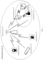
- FIG. 1 is a schematic diagram of an architecture of a communication system 100 according to an embodiment of this application.
- the communication system 100 may include a network device 110 and a terminal device 101 to a terminal device 106.
- the network device or the terminal device may be hardware, may be software obtained through functional division, or may be a combination thereof.
- the network device and the terminal device may communicate with each other through another device or network element.
- the network device 110 may send downlink data to the terminal device 101 to the terminal device 106.
- the terminal device 101 to the terminal device 106 may alternatively send uplink data to the network device 110.
- the terminal device 101 to the terminal device 106 may be a cellular phone, a smartphone, a portable computer, a handheld communication device, a handheld computing device, a satellite radio apparatus, a global positioning system, a personal digital assistant (personal digital assistant, PDA), and/or any other suitable device configured to perform communication in the wireless communication system 100.
- the network device 110 may be an access point (access point, AP), a NodeB, an evolved NodeB (environment bureau, eNB), or a 5G base station (next generation base station, gNB), and is a device, in an access network, that communicates with a wireless terminal over an air interface by using one or more sectors.
- the communication system 100 may use a public land mobile network (public land mobile network, PLMN), a device-to-device (device-to-device, D2D) network, a machine to machine (machine to machine, M2M) network, an internet of things (internet of things, IoT), or another network.
- PLMN public land mobile network
- D2D device-to-device
- M2M machine to machine
- IoT internet of things
- the terminal device 104 to the terminal device 106 may alternatively form a communication system.
- the terminal device 105 may send downlink data to the terminal device 104 or the terminal device 106.
- the method in embodiments of this application may be applied to the communication system 100 shown in FIG. 1 .
- An mmWave has a short wavelength, a high frequency, and strong attenuation, and is susceptible to rain fade and atmospheric absorption. Therefore, mobility and coverage bring a great challenge.
- the mmWave uses a narrow beam for transmission and reception. This improves coverage and mobility.
- such a beam can obtain an optimal gain only when it is ensured that main lobe directions of a receive beam and a transmit beam are aligned.
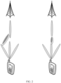
- FIG. 2 is a schematic diagram of beam alignment according to an embodiment of this application. If a beam pair on the left is selected, the main lobe directions are not aligned. Consequently, receive and transmit performance is affected. If a beam pair on the right is selected, the main lobe directions can be aligned. Therefore, an optimal receive gain and an optimal transmit gain can be obtained.
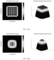
- FIG. 3(A) and FIG. 3(B) are top views and side views of a 5*5 antenna array factor gain according to an embodiment of this application. There are five sectors in each direction, 25 sectors in total. It can be learned from FIG. 3(A) and FIG.
- EIRP effective isotropic radiated power
- all receive beams may be measured and scanned once, and the foregoing process is repeated.
- all receive beams are measured and scanned once, and a beam pair of a receive beam and a transmit beam with optimal measurement values is used as an optimal beam pair.
- this solution cannot ensure that the optimal receive beam and the optimal transmit beam of the UE are used each time to form an optimal beam pair.
- FIG. 4 is a schematic flowchart of a beam alignment method according to an embodiment of this application. This embodiment of this application includes at least the following steps.
- S401 Receive, at a current location by using a plurality of receive beams, a transmit beam sent by a network device, and determine reference signal received power (reference signal receiving power, RSRP) of each of the plurality of receive beams.
- RSRP reference signal receiving power
- each transmit beam of the network device all receive beams are measured and scanned at the current location, and the RSRP of each receive beam is determined.
- S402 Select an optimal receive beam from the plurality of receive beams based on the RSRP.
- a receive beam with highest RSRP may be selected from the plurality of receive beams as the optimal receive beam.
- a terminal device forms an optimal beam pair by using the receive beam with the highest RSRP and the transmit beam of the network device.
- S403 Determine, based on the optimal receive beam, a rotation angle and a rotation direction that are required by the terminal device to align a peak direction beam with the transmit beam.
- the terminal device may determine a relative location of the peak direction beam and the optimal receive beam, and determine, based on the relative location, the rotation angle and the rotation direction that are required by the terminal device to align the peak direction beam with the transmit beam, that is, the rotation angle and the rotation direction that are required for rotating from a location of the peak direction beam to a location of the optimal receive beam.
- the peak direction beam is a beam perpendicular to an antenna panel of the network device.
- S404 Adjust a location of the terminal device based on the rotation angle and the rotation direction, and form an optimal beam pair by using the peak direction beam and the transmit beam at an adjusted location.
- a direction and an angle of the terminal device may be adjusted based on the rotation direction and the rotation angle, to adjust a radiation direction and a radiation angle of an antenna in the terminal device.
- Rotation of the terminal device is stopped when the terminal device is adjusted to a location indicated by the rotation angle and the rotation direction.
- the terminal device may align the peak direction beam with the transmit beam to form the optimal beam pair.
- the terminal device may display the rotation angle and the rotation direction.
- a user may rotate the terminal device based on the displayed rotation angle and rotation direction.
- the rotation angle and the rotation direction may be displayed in a notification bar of the terminal device, or the rotation angle and the rotation direction may be displayed in the middle of a display interface of the terminal device.
- the rotation angle and the rotation direction may be displayed by using a prompt box (for example, a popover). It should be noted that the rotation angle and the rotation direction may alternatively be displayed in another manner, and the display manner is not limited herein.
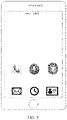
- FIG. 5 is a schematic diagram of information display according to an embodiment of this application.
- "-> (40)" is displayed in the notification bar of the terminal device, indicating to rotate the terminal device rightward by 40 degrees, so that the terminal device can form the optimal beam pair by using the peak direction beam and the transmit beam.
- the terminal device may alternatively be rotated in any direction, such as a left direction, a forward direction, or a right direction, and the rotation angle may alternatively be any angle.
- duration for displaying the rotation angle and the rotation direction exceeds a preset threshold
- displaying of the rotation angle and the rotation direction may be stopped.
- the preset threshold may be 30 seconds or 1 minute. This is not limited herein.
- the terminal device displays prompt information.
- the prompt information is used to prompt the user that adjustment of the location of the terminal device is completed.
- the user may stop rotating the location of the terminal device, so that the terminal device can form the optimal beam pair by using the peak direction beam and the transmit beam.
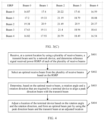
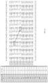
- FIG. 6 is a schematic diagram of a beam according to an embodiment of this application.
- a left side of FIG. 6 represents an ID of a receive beam that can be used by the terminal device.
- a beam 0 is a peak direction beam (bore sight direction/peak direction), and a beam 76 used at the current location and a transmit beam of a base station are used to form an optimal beam pair. Therefore, a corresponding angle between the two beams (the beam 76 and the beam 0) may be rotated, to rotate the beam 0 to a location of the beam 76, so that UE uses the beam 0 and the transmit beam of the base station to form the optimal beam pair.
- a rotation angle by which the beam 0 is rotated to the beam 76 is an angle by which the UE needs to be rotated.
- the transmit beam sent by the network device is received at the current location by using the plurality of receive beams, and the optimal receive beam is selected from the plurality of receive beams based on the RSRP of each receive beam.
- the rotation angle and the rotation direction that are required by the terminal device to align the peak direction beam with the transmit beam are determined based on the optimal receive beam.
- the location of the terminal device is adjusted based on the rotation angle and the rotation direction, and the peak direction beam and the transmit beam are used to form the optimal beam pair at the adjusted location.
- the rotation angle and the rotation direction that are required for rotating from the location of the peak direction beam to the location of the optimal receive beam are determined, so that after adjusting the location, the terminal device can form the optimal beam pair by using the peak direction beam and the transmit beam. This not only increases a transmit gain or a receive gain of the terminal device, but also improves coverage and mobility of a millimeter wave.
- FIG. 7 is a schematic diagram of a structure of a beam alignment apparatus according to an embodiment of this application.
- the beam alignment apparatus may include a receiving module 701, a selection module 702, a processing module 703, and a display module 704.
- the receiving module 701 is configured to: receive, at a current location by using a plurality of receive beams, a transmit beam sent by a network device, and determining reference signal received power RSRP of each of the plurality of receive beams.
- the selection module 702 is further configured to select an optimal receive beam from the plurality of receive beams based on the RSRP.
- the processing module 703 is further configured to determine, based on the optimal receive beam, a rotation angle and a rotation direction that are required by a terminal device to align a peak direction beam with the transmit beam.
- the processing module 703 is configured to: adjust a location of the terminal device based on the rotation angle and the rotation direction, and form an optimal beam pair by using the peak direction beam and the transmit beam at an adjusted location.
- the display module 704 is configured to display the rotation angle and the rotation direction.
- the display module 704 is configured to: display prompt information when the terminal device is adjusted to a location indicated by the rotation angle and the rotation direction.
- the prompt information is used to prompt a user that adjustment of the location of the terminal device is completed.
- the selection module 702 is further configured to select, from the plurality of receive beams, a receive beam with highest RSRP as the optimal receive beam.
- the processing module 703 is further configured to: determine a relative location of the peak direction beam and the optimal receive beam, and determine, based on the relative location, the rotation angle and the rotation direction that are required by the terminal device to align the peak direction beam with the transmit beam.
- the peak direction beam is a beam perpendicular to an antenna panel of the network device.
- each module refers to the corresponding description in the method embodiment shown in FIG. 4 , to perform the method and the function performed by the terminal device in the foregoing embodiment.
- the terminal device includes a modem, a processor, and a display.
- the modem is configured to perform the method and the function performed by the receiving module 701 and the selection module 702.
- the processor is configured to perform the method and the function performed by the processing module 703.
- the display is configured to perform the method and the function performed by the display module 704.
- FIG. 8 is a schematic diagram of a structure of a terminal device according to an embodiment of this application.
- the terminal device may include at least one processor 801, at least one communication interface 802, at least one memory 803, and at least one communication bus 804.
- the processor 801 may be a central processing unit, a general-purpose processor, a digital signal processor, an application-specific integrated circuit, a field programmable gate array or another programmable logic device, a transistor logic device, a hardware component, or any combination thereof.
- the processor may implement or execute various example logical blocks, modules, and circuits described with reference to content disclosed in this application.
- the processor may be a combination of processors implementing a computing function, for example, a combination of one or more microprocessors, or a combination of the digital signal processor and a microprocessor.
- the communication bus 804 may be a peripheral component interconnect PCI bus, an extended industry standard architecture EISA bus, or the like.
- the bus may be classified into an address bus, a data bus, a control bus, and the like. For ease of representation, only one thick line is for representing the bus in FIG. 8 , but this does not mean that there is only one bus or only one type of bus.
- the communication bus 804 is configured to implement communication connection between these components.
- the communication interface 802 of the device in this embodiment of this application is configured to perform signaling or data communication with another node device.
- the memory 803 may include a volatile memory, for example, a nonvolatile dynamic random access memory (nonvolatile random access memory, NVRAM), a phase-change random access memory (phase-change RAM, PRAM), or a magnetoresistive random access memory (magnetoresistive RAM, MRAM); or may include a nonvolatile memory, for example, at least one magnetic disk storage device, an electrically erasable programmable read-only memory (electrically erasable programmable read-only memory, EEPROM), a flash memory device such as a NOR flash memory (NOR flash memory) or a NAND flash memory (NAND flash memory), or a semiconductor device such as a solid-state drive (solid-state drive, SSD).
- the memory 803 may alternatively be at least one storage apparatus that is away from the processor 801.
- the memory 803 may further store a group of program code.
- the processor 801 may further execute a program stored in the memory 803.
- the processor 801 is configured to perform the following operation steps:
- the processor 801 is further configured to perform the following operation step: displaying the rotation angle and the rotation direction.
- the processor 801 is further configured to perform the following operation step: displaying prompt information when the terminal device is adjusted to a location indicated by the rotation angle and the rotation direction, where the prompt information is used to prompt a user that adjustment of the location of the terminal device is completed.
- the processor 801 is further configured to perform the following operation step: selecting, from the plurality of receive beams, a receive beam with highest RSRP as the optimal receive beam.
- processor 801 is further configured to perform the following operation steps:
- the peak direction beam is a beam perpendicular to an antenna panel of the network device.
- the processor may cooperate with the memory and the communication interface to perform the operations of the terminal device in the foregoing embodiments of this application.
- An embodiment of this application further provides a chip system.
- the chip system includes a processor, and is configured to support a terminal device in implementing the function in any one of the foregoing embodiments, for example, calculating a rotation angle and a rotation direction, and receiving or sending the rotation angle and the rotation direction.
- the chip system may further include a memory, and the memory is configured to store program instructions and data that are necessary for the terminal device or a network device.
- the chip system may include a chip, or may include a chip and another discrete component.
- An embodiment of this application further provides a processor, configured to be coupled to a memory, and configured to perform any method and function that are related to the terminal device in any one of the foregoing embodiments.
- An embodiment of this application further provides a computer program product including instructions. When the computer program product runs on a computer, the computer is enabled to perform any method and function that are related to the terminal device in any one of the foregoing embodiments.
- An embodiment of this application further provides an apparatus.
- the apparatus is configured to perform any method and function that are related to the terminal device in any one of the foregoing embodiments.
- An embodiment of this application further provides a wireless communication system.
- the system includes at least one terminal device and at least one network device that are involved in any one of the foregoing embodiments.
- All or some of the foregoing embodiments may be implemented by using software, hardware, firmware, or any combination thereof.
- software is used to implement embodiments, all or some of embodiments may be implemented in a form of a computer program product.
- the computer program product includes one or more computer instructions. When the computer program instructions are loaded and executed on the computer, the procedure or functions according to embodiments of this application are all or partially generated.
- the computer may be a general-purpose computer, a dedicated computer, a computer network, or other programmable apparatuses.
- the computer instructions may be stored in a computer-readable storage medium or may be transmitted from a computer-readable storage medium to another computer-readable storage medium.
- the computer instructions may be transmitted from a network device, computer, server, or data center to another network device, computer, server, or data center in a wired (for example, a coaxial cable, an optical fiber, or a digital subscriber line (DSL)) or wireless (for example, infrared, radio, or microwave) manner.
- the computer-readable storage medium may be any usable medium accessible by the computer, or a data storage device, for example, a server or a data center, integrating one or more usable media.
- the usable medium may be a magnetic medium (for example, a floppy disk, a hard disk, or a magnetic tape), an optical medium (for example, a DVD), a semiconductor medium (for example, a solid-state drive solid state disk (SSD)), or the like.
- a magnetic medium for example, a floppy disk, a hard disk, or a magnetic tape
- an optical medium for example, a DVD
- a semiconductor medium for example, a solid-state drive solid state disk (SSD)
Landscapes
- Engineering & Computer Science (AREA)
- Computer Networks & Wireless Communication (AREA)
- Signal Processing (AREA)
- Physics & Mathematics (AREA)
- General Physics & Mathematics (AREA)
- Radar, Positioning & Navigation (AREA)
- Remote Sensing (AREA)
- Mobile Radio Communication Systems (AREA)
- Radio Transmission System (AREA)
Applications Claiming Priority (2)
| Application Number | Priority Date | Filing Date | Title |
|---|---|---|---|
| CN202010497707.3A CN113765547B (zh) | 2020-06-03 | 2020-06-03 | 一种波束对齐方法及相关设备 |
| PCT/CN2021/096453 WO2021244398A1 (zh) | 2020-06-03 | 2021-05-27 | 一种波束对齐方法及相关设备 |
Publications (2)
| Publication Number | Publication Date |
|---|---|
| EP4149010A1 true EP4149010A1 (de) | 2023-03-15 |
| EP4149010A4 EP4149010A4 (de) | 2023-10-25 |
Family
ID=78783501
Family Applications (1)
| Application Number | Title | Priority Date | Filing Date |
|---|---|---|---|
| EP21817823.4A Pending EP4149010A4 (de) | 2020-06-03 | 2021-05-27 | Strahlausrichtungsverfahren und zugehörige vorrichtung |
Country Status (4)
| Country | Link |
|---|---|
| US (1) | US12601808B2 (de) |
| EP (1) | EP4149010A4 (de) |
| CN (1) | CN113765547B (de) |
| WO (1) | WO2021244398A1 (de) |
Cited By (1)
| Publication number | Priority date | Publication date | Assignee | Title |
|---|---|---|---|---|
| WO2024226027A1 (en) * | 2023-04-24 | 2024-10-31 | Nokia Technologies Oy | Methods and apparatuses for controlling received power at reception points |
Families Citing this family (1)
| Publication number | Priority date | Publication date | Assignee | Title |
|---|---|---|---|---|
| CN113765547B (zh) * | 2020-06-03 | 2023-04-07 | 华为技术有限公司 | 一种波束对齐方法及相关设备 |
Family Cites Families (17)
| Publication number | Priority date | Publication date | Assignee | Title |
|---|---|---|---|---|
| JP2000124720A (ja) * | 1998-10-12 | 2000-04-28 | Nippon Telegr & Teleph Corp <Ntt> | 無線通信装置 |
| US9853712B2 (en) * | 2014-02-17 | 2017-12-26 | Ubiqomm Llc | Broadband access system via drone/UAV platforms |
| US9753118B2 (en) * | 2014-11-25 | 2017-09-05 | Qualcomm Incorporated | Technique for obtaining the rotation of a wireless device |
| DE102015201641A1 (de) * | 2015-01-30 | 2016-08-04 | Bayerische Motoren Werke Aktiengesellschaft | Applikationsgesteuertes Geo-Beamforming |
| JP6847581B2 (ja) * | 2016-02-12 | 2021-03-24 | パナソニック インテレクチュアル プロパティ コーポレーション オブ アメリカPanasonic Intellectual Property Corporation of America | 無線通信装置、及び無線通信装置における表示方法 |
| CN105824019B (zh) * | 2016-03-18 | 2018-04-20 | 中国人民解放军63921部队 | 大型分布式空间监测雷达的最优化波束对齐方法 |
| CN108347272B (zh) * | 2017-01-25 | 2020-12-15 | 华为技术有限公司 | 一种基于波束组进行通信的方法及设备 |
| WO2018168670A1 (ja) * | 2017-03-17 | 2018-09-20 | 株式会社Nttドコモ | ユーザ端末および測位方法 |
| CN109714780A (zh) * | 2017-10-26 | 2019-05-03 | 华为技术有限公司 | 通信方法、终端和接入网设备 |
| CN110098856B (zh) * | 2018-01-31 | 2021-06-22 | 华为技术有限公司 | 一种天线装置及相关设备 |
| CN110445523B (zh) * | 2018-05-04 | 2023-02-14 | 华为技术有限公司 | 波束训练方法、相关装置及系统 |
| CN111163480A (zh) * | 2018-11-07 | 2020-05-15 | 索尼公司 | 电子装置、无线通信方法和计算机可读介质 |
| CN109996265B (zh) * | 2019-04-02 | 2021-08-03 | 华为技术有限公司 | 波束测量方法、装置、系统、网络设备和终端设备 |
| CN110212963B (zh) * | 2019-05-24 | 2022-04-15 | Oppo广东移动通信有限公司 | 波束跟踪方法、装置及计算机存储介质和终端设备 |
| CN113765547B (zh) * | 2020-06-03 | 2023-04-07 | 华为技术有限公司 | 一种波束对齐方法及相关设备 |
| CN114449099B (zh) * | 2020-11-02 | 2023-07-28 | 华为技术有限公司 | 一种设备方位调整的方法、终端设备和可读存储介质 |
| US12143196B2 (en) * | 2021-09-24 | 2024-11-12 | Qualcomm Incorporated | Relative beam direction indication for beam management |
-
2020
- 2020-06-03 CN CN202010497707.3A patent/CN113765547B/zh active Active
-
2021
- 2021-05-27 WO PCT/CN2021/096453 patent/WO2021244398A1/zh not_active Ceased
- 2021-05-27 US US18/007,896 patent/US12601808B2/en active Active
- 2021-05-27 EP EP21817823.4A patent/EP4149010A4/de active Pending
Cited By (1)
| Publication number | Priority date | Publication date | Assignee | Title |
|---|---|---|---|---|
| WO2024226027A1 (en) * | 2023-04-24 | 2024-10-31 | Nokia Technologies Oy | Methods and apparatuses for controlling received power at reception points |
Also Published As
| Publication number | Publication date |
|---|---|
| US20240230816A1 (en) | 2024-07-11 |
| CN113765547A (zh) | 2021-12-07 |
| WO2021244398A1 (zh) | 2021-12-09 |
| EP4149010A4 (de) | 2023-10-25 |
| US12601808B2 (en) | 2026-04-14 |
| CN113765547B (zh) | 2023-04-07 |
Similar Documents
| Publication | Publication Date | Title |
|---|---|---|
| US20250227660A1 (en) | Positioning method and apparatus | |
| US12155439B2 (en) | Systems and methods for user equipment (UE) selection from among asymmetric uplink (UL) antenna panels | |
| WO2021097598A1 (zh) | 侧行定位方法和装置 | |
| CN110753388A (zh) | 一种波束管理方法和相关设备 | |
| EP3592048B1 (de) | Leistungsbestimmungsverfahren, -vorrichtung und -system | |
| EP4456603A1 (de) | Verfahren und vorrichtung zur zellenmobilitätsverwaltung | |
| CN111277294B (zh) | 天线选择方法及相关产品 | |
| US8971816B2 (en) | Method and arrangement for assisting in direction adjustment of a directional antenna | |
| US12601808B2 (en) | Beam alignment method and related device | |
| US20200252963A1 (en) | Random access method and user terminal | |
| WO2022027295A1 (en) | Systems and methods for providing network indications for selecting asymmetric uplink (ul) antenna panels at user equipment (ue) | |
| EP4629689A1 (de) | Strahlmessverfahren und zugehörige vorrichtung | |
| US20230254902A1 (en) | Communication method and apparatus | |
| US12028769B2 (en) | mmWave to Wi-Fi control signal offloading in the event of fading in the mmWave system | |
| EP4221391A1 (de) | Kommunikationsverfahren und -vorrichtung | |
| CN110784820B (zh) | 无线网络设备定位方法、装置、存储介质及无线网络设备 | |
| CN112994766B (zh) | 一种波束传输方法及相关设备 | |
| CN111183601A (zh) | 分布式系统中的天线参数控制 | |
| CN109089279A (zh) | 一种基于多波束的功率控制方法、用户终端和基站 | |
| JP2023500145A (ja) | 接続再開方法及び装置 | |
| US12526766B2 (en) | Automated determination of access-point geographic locations | |
| US11777601B1 (en) | Systems and methods for providing wireless communications to a device using both optical and radio frequency transmission | |
| CN106304256A (zh) | 接入方法和接入装置 | |
| WO2025160803A1 (en) | Enhancement of early data transmission (edt) and preconfigured uplink resource (pur) in internet of things (iot) non-terrestrial networks (ntn) | |
| US11877323B2 (en) | Random access method, user equipment and network side device |
Legal Events
| Date | Code | Title | Description |
|---|---|---|---|
| STAA | Information on the status of an ep patent application or granted ep patent |
Free format text: STATUS: THE INTERNATIONAL PUBLICATION HAS BEEN MADE |
|
| PUAI | Public reference made under article 153(3) epc to a published international application that has entered the european phase |
Free format text: ORIGINAL CODE: 0009012 |
|
| STAA | Information on the status of an ep patent application or granted ep patent |
Free format text: STATUS: REQUEST FOR EXAMINATION WAS MADE |
|
| 17P | Request for examination filed |
Effective date: 20221205 |
|
| AK | Designated contracting states |
Kind code of ref document: A1 Designated state(s): AL AT BE BG CH CY CZ DE DK EE ES FI FR GB GR HR HU IE IS IT LI LT LU LV MC MK MT NL NO PL PT RO RS SE SI SK SM TR |
|
| DAV | Request for validation of the european patent (deleted) | ||
| DAX | Request for extension of the european patent (deleted) | ||
| A4 | Supplementary search report drawn up and despatched |
Effective date: 20230922 |
|
| RIC1 | Information provided on ipc code assigned before grant |
Ipc: G01S 3/02 20060101ALI20230918BHEP Ipc: H04B 7/08 20060101ALI20230918BHEP Ipc: H04W 72/044 20230101ALI20230918BHEP Ipc: H04W 16/28 20090101ALI20230918BHEP Ipc: H04B 7/06 20060101ALI20230918BHEP Ipc: H04B 7/0408 20170101AFI20230918BHEP |
|
| STAA | Information on the status of an ep patent application or granted ep patent |
Free format text: STATUS: EXAMINATION IS IN PROGRESS |
|
| 17Q | First examination report despatched |
Effective date: 20251201 |