EP4148317A1 - Verriegelungsanordnung - Google Patents
Verriegelungsanordnung Download PDFInfo
- Publication number
- EP4148317A1 EP4148317A1 EP22194784.9A EP22194784A EP4148317A1 EP 4148317 A1 EP4148317 A1 EP 4148317A1 EP 22194784 A EP22194784 A EP 22194784A EP 4148317 A1 EP4148317 A1 EP 4148317A1
- Authority
- EP
- European Patent Office
- Prior art keywords
- plate
- locking
- striker
- face
- clip
- Prior art date
- Legal status (The legal status is an assumption and is not a legal conclusion. Google has not performed a legal analysis and makes no representation as to the accuracy of the status listed.)
- Pending
Links
Images

Classifications
-
- F—MECHANICAL ENGINEERING; LIGHTING; HEATING; WEAPONS; BLASTING
- F16—ENGINEERING ELEMENTS AND UNITS; GENERAL MEASURES FOR PRODUCING AND MAINTAINING EFFECTIVE FUNCTIONING OF MACHINES OR INSTALLATIONS; THERMAL INSULATION IN GENERAL
- F16M—FRAMES, CASINGS OR BEDS OF ENGINES, MACHINES OR APPARATUS, NOT SPECIFIC TO ENGINES, MACHINES OR APPARATUS PROVIDED FOR ELSEWHERE; STANDS; SUPPORTS
- F16M11/00—Stands or trestles as supports for apparatus or articles placed thereon ; Stands for scientific apparatus such as gravitational force meters
- F16M11/02—Heads
- F16M11/04—Means for attachment of apparatus; Means allowing adjustment of the apparatus relatively to the stand
- F16M11/041—Allowing quick release of the apparatus
-
- F—MECHANICAL ENGINEERING; LIGHTING; HEATING; WEAPONS; BLASTING
- F16—ENGINEERING ELEMENTS AND UNITS; GENERAL MEASURES FOR PRODUCING AND MAINTAINING EFFECTIVE FUNCTIONING OF MACHINES OR INSTALLATIONS; THERMAL INSULATION IN GENERAL
- F16B—DEVICES FOR FASTENING OR SECURING CONSTRUCTIONAL ELEMENTS OR MACHINE PARTS TOGETHER, e.g. NAILS, BOLTS, CIRCLIPS, CLAMPS, CLIPS OR WEDGES; JOINTS OR JOINTING
- F16B2/00—Friction-grip releasable fastenings
- F16B2/02—Clamps, i.e. with gripping action effected by positive means other than the inherent resistance to deformation of the material of the fastening
- F16B2/06—Clamps, i.e. with gripping action effected by positive means other than the inherent resistance to deformation of the material of the fastening external, i.e. with contracting action
- F16B2/12—Clamps, i.e. with gripping action effected by positive means other than the inherent resistance to deformation of the material of the fastening external, i.e. with contracting action using sliding jaws
-
- B—PERFORMING OPERATIONS; TRANSPORTING
- B60—VEHICLES IN GENERAL
- B60R—VEHICLES, VEHICLE FITTINGS, OR VEHICLE PARTS, NOT OTHERWISE PROVIDED FOR
- B60R11/00—Arrangements for holding or mounting articles, not otherwise provided for
-
- F—MECHANICAL ENGINEERING; LIGHTING; HEATING; WEAPONS; BLASTING
- F16—ENGINEERING ELEMENTS AND UNITS; GENERAL MEASURES FOR PRODUCING AND MAINTAINING EFFECTIVE FUNCTIONING OF MACHINES OR INSTALLATIONS; THERMAL INSULATION IN GENERAL
- F16M—FRAMES, CASINGS OR BEDS OF ENGINES, MACHINES OR APPARATUS, NOT SPECIFIC TO ENGINES, MACHINES OR APPARATUS PROVIDED FOR ELSEWHERE; STANDS; SUPPORTS
- F16M13/00—Other supports for positioning apparatus or articles; Means for steadying hand-held apparatus or articles
-
- G—PHYSICS
- G01—MEASURING; TESTING
- G01S—RADIO DIRECTION-FINDING; RADIO NAVIGATION; DETERMINING DISTANCE OR VELOCITY BY USE OF RADIO WAVES; LOCATING OR PRESENCE-DETECTING BY USE OF THE REFLECTION OR RERADIATION OF RADIO WAVES; ANALOGOUS ARRANGEMENTS USING OTHER WAVES
- G01S13/00—Systems using the reflection or reradiation of radio waves, e.g. radar systems; Analogous systems using reflection or reradiation of waves whose nature or wavelength is irrelevant or unspecified
- G01S13/88—Radar or analogous systems specially adapted for specific applications
- G01S13/91—Radar or analogous systems specially adapted for specific applications for traffic control
- G01S13/92—Radar or analogous systems specially adapted for specific applications for traffic control for velocity measurement
-
- G—PHYSICS
- G01—MEASURING; TESTING
- G01S—RADIO DIRECTION-FINDING; RADIO NAVIGATION; DETERMINING DISTANCE OR VELOCITY BY USE OF RADIO WAVES; LOCATING OR PRESENCE-DETECTING BY USE OF THE REFLECTION OR RERADIATION OF RADIO WAVES; ANALOGOUS ARRANGEMENTS USING OTHER WAVES
- G01S7/00—Details of systems according to groups G01S13/00, G01S15/00, G01S17/00
- G01S7/02—Details of systems according to groups G01S13/00, G01S15/00, G01S17/00 of systems according to group G01S13/00
- G01S7/027—Constructional details of housings, e.g. form, type, material or ruggedness
-
- B—PERFORMING OPERATIONS; TRANSPORTING
- B60—VEHICLES IN GENERAL
- B60R—VEHICLES, VEHICLE FITTINGS, OR VEHICLE PARTS, NOT OTHERWISE PROVIDED FOR
- B60R11/00—Arrangements for holding or mounting articles, not otherwise provided for
- B60R2011/0042—Arrangements for holding or mounting articles, not otherwise provided for characterised by mounting means
- B60R2011/0049—Arrangements for holding or mounting articles, not otherwise provided for characterised by mounting means for non integrated articles
- B60R2011/0064—Connection with the article
Definitions
- the invention generally relates to the field of removable and manual locking of two elements.
- the invention finds particular application in the case of locking a part on a support of the tripod type, even more particularly when the part is bulky and has a certain weight.
- the invention can be implemented in the locking of a vehicle control radar on its support.
- locking assemblies configured to removably and manually secure a part to a support, such as a tripod.
- Such locking assemblies may comprise, in the typical case of an image capture device of the video camera or photo camera type, screwing means making it possible to secure the device and its tripod.
- screwing means do not allow solid and robust fixing and are difficult to envisage when the part to be fixed is bulky and heavy, as is particularly the case with a vehicle control radar.
- these radars must be fixed in height, so that the operator must act blind, that is to say without seeing the locking assembly during the coupling of the elements, or be assisted.
- An object of the invention is to remedy the aforementioned drawbacks, by proposing an assembly for fixing a first element to a second element, in particular a vehicle control radar on a tripod-type support, which can be locked and unlocked. manually and blind by an operator, which is simple to make and easily adaptable to any type of element, regardless of its size and weight.
- the second element is a vehicle control radar and the first element is a support.
- the first stage is configured to be fixedly mounted on one of the support and the vehicle control radar.
- the second plate is configured to be fixedly mounted on the other of the vehicle control radar and the support.
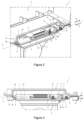
- the invention will more particularly be described in the case of the locking of a vehicle control system comprising a vehicle control radar 2 and a tripod 3.
- the locking assembly 1 of the invention can be implemented in the removable attachment of any two parts.
- the locking assembly 1 comprises a first plate 4 and a second plate 5 configured to be mounted respectively on the tripod 3 and the vehicle control radar 2.
- Each plate 4, 5 comprises a first face, or upper face, and a second face, or lower face, the upper face 7 of the first plate 4 being configured to be placed facing the lower face 6 of the second plate 5.
- first plate 4 is mounted fixed on the tripod 3 while the second plate 5 is mounted fixed on the radar 2.
- the first plate 4 will therefore be called “lower plate 4 and the second deck 5 "upper deck 5" to simplify reading.
- this is not limiting, the first plate 4 being able to be fixed on the radar 2 and being under the second plate 5 which would then be fixed on the tripod 3.
- the upper plate 5 and the lower plate 4 can be substantially planar. They may in particular each comprise a metal sheet, which are made of any suitable material such as aluminum or steel.
- the locking assembly 1 further comprises an abutment 8 configured to block the first plate 4 in translation relative to the second plate 5 in a first direction A along a locking direction X, as well as a movable lock 9 in translation along the locking direction X and which is configured to block the upper plate 5 in translation relative to the lower plate 4 in a second direction B which is opposite to the first direction A.
- the simple actuation of the lock 9 thus allows to lock or unlock the upper plate 5 on the lower plate 4, according to the direction of translation chosen along the locking direction X.
- the lock 9 comprises a striker plate 10, a clip 11 and a housing 12 configured to receive the clip 11.
- the striker 10 is mounted on one of the upper plate 5 or the lower plate 4.
- the striker 10 is mounted on the upper face 7 of the upper plate 5, which comprises then a through passage 13 making it possible to partially reveal the striker 10 and to allow the cooperation of the clip 11 with the housing 12.
- the striker 10 could be mounted on the lower face 6 of the upper plate 5.
- mounting the strike plate 10 on the plate located above has the advantage of being more ergonomic for the operator.
- the keeper 10 is also movable in translation along the locking direction X between a locking configuration and an unlocking configuration.
- the striker 10 can for example be mounted on the upper plate 5 by means of a sliding connection 14.
- the sliding connection 14 can typically comprise at least one rail formed in the upper plate 5 and a series of bolts.
- each bolt comprises a screw and a nut, the head of the screw being placed in the rail while its rod is inserted into corresponding holes formed in the striker plate 10 and fixed on the striker plate 10 using of the corresponding nut.
- washers are fitted onto the shank of the bolts and housed within the holes of the striker 10.
- the spacers 15 have a thickness greater than that of the keeper 10 in order to facilitate the tightening of the bolts.
- Striker 10 may include a handle 16 to facilitate handling of lock 9 by the operator. This handle 16 is preferably placed close to an edge of the keeper 10 in order to be easily accessible by the operator.
- the handle 16 is oriented perpendicular to the locking direction X in order to facilitate the actuation of the mechanism by the operator.
- the clip 11 is fixed on one of the upper face 7 of the lower plate 4 and the striker 10 while the housing 12 is formed in the other of the upper face 7 of the lower plate 4 and the striker 10 and is configured to receive the clip 11.
- the clip 11 is fixed on the upper face 7 of the lower plate 4 and protrudes in the direction of the striker 10 while the housing 12 is formed in the striker 10.
- the housing 12 is here a through hole, it is that is to say which opens onto the two opposite faces of the striker 10 in order to allow the clip 11 to pass right through it, and which is delimited by an internal edge 17 of the striker 10.
- the keeper 10 can be thick and the housing 12 deep enough to receive the entire volume of the clip 11.
- the striker 10 being here placed against the upper face 7 of the upper plate 5, the housing 12 also extends in the extension of the through passage 13 formed in the upper plate 5 in order to be able to receive the fastener 11.
- a locking groove 18 is formed in the face of the clip 11 which is opposite the abutment 8.
- the clip 11 includes a chamfer 19 allowing the edge 17 of the housing 12 to slide along the clip 11 to the groove of the blocking 18.
- the blocking groove 18 is formed in the base 20b of the chamfer 19 (close to the lower plate 4), and the chamfer 19 is shaped so as to converge from the base 20b of the fastener 11 , close to the locking groove 18, in the direction of the housing 12.
- the surface of the chamfer 19 is therefore inclined and forms an acute angle at the level of its vertex 20a which can be between 35° and 60°, preferably between 40 ° and 50°.
- the clip 11 may have a substantially square base section 20b and include lateral chamfers 21 (visible for example on the figure 1 And 3 ) perpendicular to the chamfer 19 and which converge from the base 20b to the top 20 of the clip.
- lateral chamfers 21 also participate in guiding the edge 17 of the housing 12, in particular when the width of the housing in a direction perpendicular to the locking direction is at most equal to 120% of the width in this direction of the fastener 11 This adjustment of the width of the housing 12 relative to the width of the clip 11 limits the risks of untimely release of the clip 11.
- the clip 11 and the keeper 10 are preferably made of materials resistant to wear and friction, typically stainless steel.
- the attachment 11 can be made of the same material as the lower plate 4, in which case it can be monolithic with the lower plate 4, or made of a material distinct from the lower plate 4, for example for questions of cost or density, in which case it can be attached and fixed to the lower plate 4.
- the clip 11 can be fixed to the lower plate 4 using a screw 22. If necessary, the head of the screw can be milled so as not to protrude from the lower face 6 of the lower plate 4.
- the clip 11 is fixed on the striker plate 10 and protrudes (if necessary, through the through passage 13 formed in the upper plate 5) in the direction of the upper face 7 of the lower plate 4, while the housing 12 is formed and opens into the upper face 7 of the lower plate 4.
- the striker 10 is connected to the upper plate 5 via a return means 23 configured to bring the striker 10 back to its locked configuration.
- the return means 23 may in particular comprise a spring 23 in tension.
- the spring 23 may comprise a first end fixed to the upper plate 5, preferably on the same face as the striker 10, and a second end fixed to the striker 10.
- the return spring 23 is aligned with the locking direction X and is positioned on the upper plate 5 so as to be opposite the handle 16.
- the stiffness of the spring 23 is also chosen so that, in the absence of forces applied to the striker 10, the spring 23 brings and maintains the striker 10 in its locked configuration and that, when an operator applies a reasonable effort on the keeper 10, he can bring it without difficulty in its unlocked configuration.
- the stiffness of the spring 23 can for example be between 3 and 3.6 N/mm. In this way, when an operator locks the radar 2 on the tripod 3, it suffices for him to place the top 20a of the attachment 11 facing the housing 12 then to let the edge of the housing 12 slide along the chamfer 19 of the attachment 11.
- the chamfer 19 applies a force to the striker plate 10 which is opposed to the return force of the spring 23 and surpasses it, which moves the keeper 10 to its unlocking configuration.
- the operator does not need to pull the handle 16 in the second direction along the locking direction X.
- the operator can hold the radar 2, which is very heavy and bulky, with both hands.
- the chamfer 19 no longer offers resistance to the striker 10: the return force applied to the striker 10 by the spring 23 then has the effect of bringing it automatically in its locked configuration.
- the entry of the edge 17 into the locking groove 18 can generate a sound effect (clicking) confirming to the operator the engagement of the clip 11 and the edge 17.
- the spring 23 then ensures maintaining the edge 17 in the locking groove 18, which limits the risk of untimely release of the clip 11 from the housing 12, even when the radar 2 is tilted. It then suffices for an operator to release the edge 17, for example by pulling the handle 16 of the striker plate 10, to separate the plates 4, 5.
- the return means 23 may comprise a compression spring.
- the spring 23 is then placed on the side of the handle 16 in order to be able to bring and maintain the keeper 10 in its locked configuration. Mounting a spring 23 in compression, however, risks being more cumbersome than mounting a spring 23 in tension, given the presence of the handle 16.
- the stop 8 can comprise any means making it possible to place the upper plate 5 in axial abutment with respect to the lower plate 4 along the locking direction X.
- the abutment 8 may for example comprise a lug 24 extending from the lower plate 4 which is configured to be inserted into an opening 25 formed in the upper plate 5 and come to rest against a wall 26 delimiting this opening 25.
- the lug 24 may for example comprise a plate extending from the upper face 7 of the lower plate 4 forming an obtuse angle therewith.
- This embodiment thus makes it possible to produce a stop 8 very simply, for example by bending the lower plate 4 so as to obtain the lug 24 inclined and by producing, for example by laser, the opening 25 in the upper plate 5
- the lower plate 4 can be trimmed in order to form notches 27 on either side of the fold of the tab 24 and which extend from the fold in the direction of the striker 10.
- the notches 27 then allow to limit defects and burrs when bending the tab 24 and, optionally, to come into engagement with the wall 26 of the upper plate 5.
- the tab 24 and the upper plate 5 are then monolithic, which simplifies the manufacture of the lock assembly 1.
- the upper plate 5 may comprise a flange 28 which extends from the wall 26 delimiting the opening 25 formed in the upper plate 5.
- the flange 28 extends substantially parallel to the leg 24. so, when the tab 24 is introduced into the opening 25 formed in the upper plate 5, its lower surface comes into surface contact with the lower surface of the rim 28, when the upper plate 5 is locked with respect to the lower plate 4.
- the leg 24 is in surface contact with the rim 28, the lower face 6 of the upper plate 5 and the upper face 7 of the lower plate 4 are in surface contact whereas it is the lower surface of the leg 24 (In the extension of the face opposite to the upper face 7) which is in surface contact with the lower surface of the flange 28 (in the extension of the face opposite to the lower face 6).
- the faces of the plates 4, 5 which are in surface contact on the leg 24 and rim 28 parts are opposite the faces 6, 7 of the plates 4, 5 which are in contact on the main plane parts.
- the parts in contact on one side of a plate are in contact on the other side at the level of the tab 24 and the rim 28.
- the lug 24 and the rim 28 are inclined with respect to the faces 6, 7 of the corresponding plate 4, 5.
- the leg 24 and the flange 28 can for example form a angle between 100° and 150°, preferably between 120° and 140°, with the corresponding plate 5, 4.
- tab 24 relative to flange 28 as well as their inclination relative to plates 5, 4 allows, when tab 24 and flange 28 are in surface contact, that upper plate 5 is locked in translation relative at the lower plate 4 along the locking direction X and in the direction normal to the upper face 7 of the lower plate 4.
- the leg 24 and the flange 28 can also be monolithic with the corresponding plate.
- the lug 24 and the rim 28 are for example obtained by bending the corresponding plate 4, 5.
- the lug 24 and the rim 28 extend from the edge of the corresponding plate 5, 4 which is opposite the lock 9.
- This configuration makes it possible to improve the engagement of the lock 9 and the stop 8 (which apply forces in the opposite direction to the plates 4, 5) as well as the ergonomics of the locking assembly 1.
- the opening 25 is delimited by two longitudinal edges 251a, 251b oriented along the locking direction X. These longitudinal edges 251a, 251b can if necessary form guides for sliding in translation of the tab 24 within the opening 25 up to the wall 26 and/or the rim 28.
- a length of the longitudinal edges 251a, 251b of the opening 25 along the locking direction is at least equal to two centimeters, preferably at least equal to five centimeters, in order to simplify blind insertion of the tab 24 in the opening 25 then its sliding within the opening along the two guides formed by said longitudinal edges 251a, 251b.
- the abutment 8 comprises one or more studs extending from one of the lower face 6 of the upper plate 5 and the upper face 7 of the lower plate 4 and as many holes formed in the other among the lower face 6 of the upper plate 5 and the upper face 7 of the lower plate 4 configured to receive a corresponding pad.
- the spring 23 in traction, the striker 10 and if necessary the handle 16 are aligned, preferably successively, along the locking direction X.
- This configuration makes it possible to prevent the plates 4, 5 from pivoting relative to each other when the clip 11 is locked in the housing 12 and the plates 4, 5 are in abutment. It also makes the locking assembly 1 particularly ergonomic and easy to engage for the operator.
- the plates 4, 5 can be mounted on any element, and in particular any radar 2 and any tripod 3.
- each plate 4, 5 comprises at least four holes 30.
- a greater number of holes 30 can be provided in order to allow the adaptation of the plates 4, 5 on a greater number of radars 2 and tripods 3 .
- the locking of the assembly 1 can be carried out as follows, for example in the case of the locking of a radar 2 on a tripod 3.
- the tripod 3 is preferably placed upright (vertically) on the ground.
- the lower plate 4 is fixed to the top 20a of the tripod 3 and extends parallel to the ground (horizontally).
- the upper plate 5 is fixed on the lower face of the radar 2. If necessary, the lower face of the radar 2 can be arranged in order to allow the fixing of the upper plate 5 and the insertion of the clip 11 in the housing 12 For example, a recess can be formed in the underside of the radar 2 in order to receive without contact the spring 23, the striker 10 and the clip 11.
- the plates 4, 5 can for example be fixed by screwing on the radar 2 and the tripod 3.
- a mobile radar 2 comprising an upper plate 5 onto a fixed tripod 3 comprising a lower plate 4, the operator first abuts the two plates 4, 5, in particular by positioning the radar 2 so that the lug 24 of the lower plate 4 is placed in the opening 25 of the upper plate 5. Then, the operator slides the upper plate 5 of the radar 2 along the locking direction X and the second direction B until that the lug 24 reaches the end of its travel against the wall 26 of the opening 25.
- the upper plate 5 comprises a rim 28
- the sliding of the lug 24 within the opening 25 is carried out in the direction of the rim 28.
- the tab 24 and the flange 28 are in contact against each other.
- the upper plate 5 is then in axial abutment against the lower plate 4, which blocks the radar 2 with respect to the tripod 3 in the second direction B.
- the radar 2 pivots around the contact surface of the tab 24 and the rim 28.
- This movement makes it possible to place the clip 11 in the housing 12.
- the edge 17 of the housing 12 slides along the chamfer 19 of the 11 until it reaches the locking groove 18.
- This movement has the effect of overcoming the force applied by the spring 23 on the striker 10 and to translate the striker 10 with respect to the upper plate 5, thanks in particular to the weight applied by the radar 2 on the attachment 11.
- the force applied by the spring 23 has the effect of bringing the striker 10 back (in the first direction A ) against the clip 11, under the locking groove 18.
- a sound effect can be generated (clicking), thus confirming the locking of the radar 2 on the tripod 3 (that is to say the locking of the assembly 1) .
- the upper face 7 of the clip 11 is in abutment against the upper face 7 of the keeper 10 and is held in this position by the spring 23, which prevents any untimely separation of the plates 4, 5.
- the operator pulls on the handle 16 in the second direction B, thus freeing the edge 17 of the housing 12 from the locking groove 18 of the attack 11. Then, keeping the handle pulled, the operator rotates the radar 2 around the leg 24 so as to move the plates 4, 5 away from each other. In particular, the radar 2 pivots around the contact surface of the lug 24 and the rim 28. This allows the clip 11 to come out of the housing 12. Once the clip 11 has come out of the housing 12, the operator slide the upper plate 5 to move the wall 26 and, if applicable, the rim 28 away from the tab 24 along the locking direction X and the first direction A. Then, the operator raises the radar 2 to release the tab 24 from the opening 25 formed in the upper plate 5.
- a vehicle control radar 2 can weigh up to 10 kg and is generally fixed blind on a tripod 3 at 1.60 m in height.
- the locking assembly 1 thus makes it possible to make the removable fixing of the radar 2, which is heavy, on the tripod 3, which is relatively high, in a simple, fast and ergonomic manner.
Landscapes
- Engineering & Computer Science (AREA)
- General Engineering & Computer Science (AREA)
- Mechanical Engineering (AREA)
- Radar, Positioning & Navigation (AREA)
- Remote Sensing (AREA)
- Physics & Mathematics (AREA)
- Computer Networks & Wireless Communication (AREA)
- General Physics & Mathematics (AREA)
- Electromagnetism (AREA)
- Connection Of Plates (AREA)
- Clamps And Clips (AREA)
Applications Claiming Priority (1)
| Application Number | Priority Date | Filing Date | Title |
|---|---|---|---|
| FR2109644A FR3127004B1 (fr) | 2021-09-14 | 2021-09-14 | Ensemble de verrouillage |
Publications (1)
| Publication Number | Publication Date |
|---|---|
| EP4148317A1 true EP4148317A1 (de) | 2023-03-15 |
Family
ID=78212299
Family Applications (1)
| Application Number | Title | Priority Date | Filing Date |
|---|---|---|---|
| EP22194784.9A Pending EP4148317A1 (de) | 2021-09-14 | 2022-09-09 | Verriegelungsanordnung |
Country Status (4)
| Country | Link |
|---|---|
| US (1) | US12104632B2 (de) |
| EP (1) | EP4148317A1 (de) |
| AU (1) | AU2022231704A1 (de) |
| FR (1) | FR3127004B1 (de) |
Citations (2)
| Publication number | Priority date | Publication date | Assignee | Title |
|---|---|---|---|---|
| US9907416B1 (en) * | 2016-10-14 | 2018-03-06 | Steven R. Taylor | Devices for removably mounting an interface device |
| US20180224539A1 (en) * | 2017-02-07 | 2018-08-09 | Olivier Pouille | Portable enclosed speed limit radar |
Family Cites Families (6)
| Publication number | Priority date | Publication date | Assignee | Title |
|---|---|---|---|---|
| JPH0543571Y2 (de) * | 1988-09-30 | 1993-11-02 | ||
| EP1632680A1 (de) * | 2004-09-07 | 2006-03-08 | Fiberline A/S | Verfahren zum Verbinden zweier zieh-stranggepressten, profilierten Platten und Haltevorrichtung hierzu |
| US7273203B2 (en) * | 2005-02-23 | 2007-09-25 | Carnevali Jeffrey D | Locking device support |
| JP5002688B2 (ja) * | 2010-07-12 | 2012-08-15 | 本田技研工業株式会社 | 筐体取付構造 |
| US9135957B2 (en) * | 2011-03-03 | 2015-09-15 | Hewlett-Packard Development Company, L.P. | Electronic storage device mounts |
| US10660306B2 (en) * | 2017-07-31 | 2020-05-26 | Dylan Ernst | Device for securing feed or water bucket |
-
2021
- 2021-09-14 FR FR2109644A patent/FR3127004B1/fr active Active
-
2022
- 2022-09-09 EP EP22194784.9A patent/EP4148317A1/de active Pending
- 2022-09-13 US US17/943,408 patent/US12104632B2/en active Active
- 2022-09-14 AU AU2022231704A patent/AU2022231704A1/en active Pending
Patent Citations (2)
| Publication number | Priority date | Publication date | Assignee | Title |
|---|---|---|---|---|
| US9907416B1 (en) * | 2016-10-14 | 2018-03-06 | Steven R. Taylor | Devices for removably mounting an interface device |
| US20180224539A1 (en) * | 2017-02-07 | 2018-08-09 | Olivier Pouille | Portable enclosed speed limit radar |
Also Published As
| Publication number | Publication date |
|---|---|
| AU2022231704A1 (en) | 2023-03-30 |
| FR3127004B1 (fr) | 2024-09-13 |
| FR3127004A1 (fr) | 2023-03-17 |
| US20230077656A1 (en) | 2023-03-16 |
| US12104632B2 (en) | 2024-10-01 |
Similar Documents
| Publication | Publication Date | Title |
|---|---|---|
| EP2451697B1 (de) | Vorrichtung und verfahren zur einstellung der position zwischen einem frontflügel und einer vordertür eines fahrzeuges | |
| EP1178175A1 (de) | System zur Positionierung und Zusammenbau eines Fensters auf einem Fensterheber | |
| EP2952975A1 (de) | Vorrichtung zum Zusammenbau eines Gehäuserings im Gehäusemittelteil einer Armbanduhr | |
| FR3038505A1 (fr) | Poignee amovible | |
| EP2407620B1 (de) | Pfostenprofil für Haltevorrichtung eines schwenkbaren Türflügels, und eine eines solchen Pfosten umfassende Haltevorrichtung | |
| FR2937071A1 (fr) | Serrure de capot de vehicule automobile | |
| EP4148317A1 (de) | Verriegelungsanordnung | |
| WO2021058894A1 (fr) | Pièce d'assemblage pour connecter une planche de bord à une partie de caisse d'un véhicule | |
| FR2946156A1 (fr) | Dispositif de visualisation tete haute | |
| EP3360442B1 (de) | Anordnungssystem mit einem element und einem gegenelement | |
| EP1808557B1 (de) | Verriegelungsbeschlag | |
| FR3113559A3 (fr) | Dispositif d’ajustement d'extension pour boîte de pêche et dispositif d’ajustement d'extension pour tube de pied | |
| EP4265868B1 (de) | Befestigungsvorrichtung für einen griff | |
| FR2735443A1 (fr) | Verroux d'ancrage des pieds de sieges d'aeronefs dans des glissieres destinees a cette fin | |
| EP3902756B1 (de) | Eingebettetes system zum transport von gütern | |
| EP1308588A1 (de) | Ver- und Entriegelungsvorrichtung mit mehreren Riegeln für eine Schiebetür | |
| EP2299039B1 (de) | Verriegelungs-/Entriegelungsvorrichtung eines Garagentors oder Ähnlichem | |
| FR2825406A1 (fr) | Dispositif de montage a articulation d'un ouvrant sur un dormant et armoire electrique a deux sens d'ouverture comportant un tel dispositif | |
| EP2834102A1 (de) | Einheit zur steuerung der öffnungsbewegung einer tür von innen | |
| EP4717634A1 (de) | Vorrichtung zur befestigung einer förderrolle | |
| FR2908442A1 (fr) | Ferrure de chant d'un ouvrant a taquet mobile de fixation et ouvrant equipe d'une telle ferrure de chant | |
| EP4091918A1 (de) | Verschlussgriff, insbesondere für seitenwände | |
| FR2952393A1 (fr) | Dispositif d'ouverture et de fermeture d'une porte sur un cadre | |
| FR3007055A1 (fr) | Dispositif de fermeture provisoire d'un element ouvrant sur un element support | |
| FR3104187A1 (fr) | Clé pour véhicule comprenant un boitier de clé amélioré |
Legal Events
| Date | Code | Title | Description |
|---|---|---|---|
| PUAI | Public reference made under article 153(3) epc to a published international application that has entered the european phase |
Free format text: ORIGINAL CODE: 0009012 |
|
| STAA | Information on the status of an ep patent application or granted ep patent |
Free format text: STATUS: REQUEST FOR EXAMINATION WAS MADE |
|
| 17P | Request for examination filed |
Effective date: 20221104 |
|
| AK | Designated contracting states |
Kind code of ref document: A1 Designated state(s): AL AT BE BG CH CY CZ DE DK EE ES FI FR GB GR HR HU IE IS IT LI LT LU LV MC MK MT NL NO PL PT RO RS SE SI SK SM TR |
|
| P01 | Opt-out of the competence of the unified patent court (upc) registered |
Effective date: 20230919 |
|
| RAP1 | Party data changed (applicant data changed or rights of an application transferred) |
Owner name: IDEMIA ROAD SAFETY FRANCE |
|
| STAA | Information on the status of an ep patent application or granted ep patent |
Free format text: STATUS: EXAMINATION IS IN PROGRESS |
|
| 17Q | First examination report despatched |
Effective date: 20250612 |