EP4148317A1 - Latch assembly - Google Patents
Latch assembly Download PDFInfo
- Publication number
- EP4148317A1 EP4148317A1 EP22194784.9A EP22194784A EP4148317A1 EP 4148317 A1 EP4148317 A1 EP 4148317A1 EP 22194784 A EP22194784 A EP 22194784A EP 4148317 A1 EP4148317 A1 EP 4148317A1
- Authority
- EP
- European Patent Office
- Prior art keywords
- plate
- locking
- striker
- face
- clip
- Prior art date
- Legal status (The legal status is an assumption and is not a legal conclusion. Google has not performed a legal analysis and makes no representation as to the accuracy of the status listed.)
- Pending
Links
Images

Classifications
-
- F—MECHANICAL ENGINEERING; LIGHTING; HEATING; WEAPONS; BLASTING
- F16—ENGINEERING ELEMENTS AND UNITS; GENERAL MEASURES FOR PRODUCING AND MAINTAINING EFFECTIVE FUNCTIONING OF MACHINES OR INSTALLATIONS; THERMAL INSULATION IN GENERAL
- F16M—FRAMES, CASINGS OR BEDS OF ENGINES, MACHINES OR APPARATUS, NOT SPECIFIC TO ENGINES, MACHINES OR APPARATUS PROVIDED FOR ELSEWHERE; STANDS; SUPPORTS
- F16M11/00—Stands or trestles as supports for apparatus or articles placed thereon ; Stands for scientific apparatus such as gravitational force meters
- F16M11/02—Heads
- F16M11/04—Means for attachment of apparatus; Means allowing adjustment of the apparatus relatively to the stand
- F16M11/041—Allowing quick release of the apparatus
-
- F—MECHANICAL ENGINEERING; LIGHTING; HEATING; WEAPONS; BLASTING
- F16—ENGINEERING ELEMENTS AND UNITS; GENERAL MEASURES FOR PRODUCING AND MAINTAINING EFFECTIVE FUNCTIONING OF MACHINES OR INSTALLATIONS; THERMAL INSULATION IN GENERAL
- F16B—DEVICES FOR FASTENING OR SECURING CONSTRUCTIONAL ELEMENTS OR MACHINE PARTS TOGETHER, e.g. NAILS, BOLTS, CIRCLIPS, CLAMPS, CLIPS OR WEDGES; JOINTS OR JOINTING
- F16B2/00—Friction-grip releasable fastenings
- F16B2/02—Clamps, i.e. with gripping action effected by positive means other than the inherent resistance to deformation of the material of the fastening
- F16B2/06—Clamps, i.e. with gripping action effected by positive means other than the inherent resistance to deformation of the material of the fastening external, i.e. with contracting action
- F16B2/12—Clamps, i.e. with gripping action effected by positive means other than the inherent resistance to deformation of the material of the fastening external, i.e. with contracting action using sliding jaws
-
- B—PERFORMING OPERATIONS; TRANSPORTING
- B60—VEHICLES IN GENERAL
- B60R—VEHICLES, VEHICLE FITTINGS, OR VEHICLE PARTS, NOT OTHERWISE PROVIDED FOR
- B60R11/00—Arrangements for holding or mounting articles, not otherwise provided for
-
- F—MECHANICAL ENGINEERING; LIGHTING; HEATING; WEAPONS; BLASTING
- F16—ENGINEERING ELEMENTS AND UNITS; GENERAL MEASURES FOR PRODUCING AND MAINTAINING EFFECTIVE FUNCTIONING OF MACHINES OR INSTALLATIONS; THERMAL INSULATION IN GENERAL
- F16M—FRAMES, CASINGS OR BEDS OF ENGINES, MACHINES OR APPARATUS, NOT SPECIFIC TO ENGINES, MACHINES OR APPARATUS PROVIDED FOR ELSEWHERE; STANDS; SUPPORTS
- F16M13/00—Other supports for positioning apparatus or articles; Means for steadying hand-held apparatus or articles
-
- G—PHYSICS
- G01—MEASURING; TESTING
- G01S—RADIO DIRECTION-FINDING; RADIO NAVIGATION; DETERMINING DISTANCE OR VELOCITY BY USE OF RADIO WAVES; LOCATING OR PRESENCE-DETECTING BY USE OF THE REFLECTION OR RERADIATION OF RADIO WAVES; ANALOGOUS ARRANGEMENTS USING OTHER WAVES
- G01S13/00—Systems using the reflection or reradiation of radio waves, e.g. radar systems; Analogous systems using reflection or reradiation of waves whose nature or wavelength is irrelevant or unspecified
- G01S13/88—Radar or analogous systems specially adapted for specific applications
- G01S13/91—Radar or analogous systems specially adapted for specific applications for traffic control
- G01S13/92—Radar or analogous systems specially adapted for specific applications for traffic control for velocity measurement
-
- G—PHYSICS
- G01—MEASURING; TESTING
- G01S—RADIO DIRECTION-FINDING; RADIO NAVIGATION; DETERMINING DISTANCE OR VELOCITY BY USE OF RADIO WAVES; LOCATING OR PRESENCE-DETECTING BY USE OF THE REFLECTION OR RERADIATION OF RADIO WAVES; ANALOGOUS ARRANGEMENTS USING OTHER WAVES
- G01S7/00—Details of systems according to groups G01S13/00, G01S15/00, G01S17/00
- G01S7/02—Details of systems according to groups G01S13/00, G01S15/00, G01S17/00 of systems according to group G01S13/00
- G01S7/027—Constructional details of housings, e.g. form, type, material or ruggedness
-
- B—PERFORMING OPERATIONS; TRANSPORTING
- B60—VEHICLES IN GENERAL
- B60R—VEHICLES, VEHICLE FITTINGS, OR VEHICLE PARTS, NOT OTHERWISE PROVIDED FOR
- B60R11/00—Arrangements for holding or mounting articles, not otherwise provided for
- B60R2011/0042—Arrangements for holding or mounting articles, not otherwise provided for characterised by mounting means
- B60R2011/0049—Arrangements for holding or mounting articles, not otherwise provided for characterised by mounting means for non integrated articles
- B60R2011/0064—Connection with the article
Definitions
- the invention generally relates to the field of removable and manual locking of two elements.
- the invention finds particular application in the case of locking a part on a support of the tripod type, even more particularly when the part is bulky and has a certain weight.
- the invention can be implemented in the locking of a vehicle control radar on its support.
- locking assemblies configured to removably and manually secure a part to a support, such as a tripod.
- Such locking assemblies may comprise, in the typical case of an image capture device of the video camera or photo camera type, screwing means making it possible to secure the device and its tripod.
- screwing means do not allow solid and robust fixing and are difficult to envisage when the part to be fixed is bulky and heavy, as is particularly the case with a vehicle control radar.
- these radars must be fixed in height, so that the operator must act blind, that is to say without seeing the locking assembly during the coupling of the elements, or be assisted.
- An object of the invention is to remedy the aforementioned drawbacks, by proposing an assembly for fixing a first element to a second element, in particular a vehicle control radar on a tripod-type support, which can be locked and unlocked. manually and blind by an operator, which is simple to make and easily adaptable to any type of element, regardless of its size and weight.
- the second element is a vehicle control radar and the first element is a support.
- the first stage is configured to be fixedly mounted on one of the support and the vehicle control radar.
- the second plate is configured to be fixedly mounted on the other of the vehicle control radar and the support.
- the invention will more particularly be described in the case of the locking of a vehicle control system comprising a vehicle control radar 2 and a tripod 3.
- the locking assembly 1 of the invention can be implemented in the removable attachment of any two parts.
- the locking assembly 1 comprises a first plate 4 and a second plate 5 configured to be mounted respectively on the tripod 3 and the vehicle control radar 2.
- Each plate 4, 5 comprises a first face, or upper face, and a second face, or lower face, the upper face 7 of the first plate 4 being configured to be placed facing the lower face 6 of the second plate 5.
- first plate 4 is mounted fixed on the tripod 3 while the second plate 5 is mounted fixed on the radar 2.
- the first plate 4 will therefore be called “lower plate 4 and the second deck 5 "upper deck 5" to simplify reading.
- this is not limiting, the first plate 4 being able to be fixed on the radar 2 and being under the second plate 5 which would then be fixed on the tripod 3.
- the upper plate 5 and the lower plate 4 can be substantially planar. They may in particular each comprise a metal sheet, which are made of any suitable material such as aluminum or steel.
- the locking assembly 1 further comprises an abutment 8 configured to block the first plate 4 in translation relative to the second plate 5 in a first direction A along a locking direction X, as well as a movable lock 9 in translation along the locking direction X and which is configured to block the upper plate 5 in translation relative to the lower plate 4 in a second direction B which is opposite to the first direction A.
- the simple actuation of the lock 9 thus allows to lock or unlock the upper plate 5 on the lower plate 4, according to the direction of translation chosen along the locking direction X.
- the lock 9 comprises a striker plate 10, a clip 11 and a housing 12 configured to receive the clip 11.
- the striker 10 is mounted on one of the upper plate 5 or the lower plate 4.
- the striker 10 is mounted on the upper face 7 of the upper plate 5, which comprises then a through passage 13 making it possible to partially reveal the striker 10 and to allow the cooperation of the clip 11 with the housing 12.
- the striker 10 could be mounted on the lower face 6 of the upper plate 5.
- mounting the strike plate 10 on the plate located above has the advantage of being more ergonomic for the operator.
- the keeper 10 is also movable in translation along the locking direction X between a locking configuration and an unlocking configuration.
- the striker 10 can for example be mounted on the upper plate 5 by means of a sliding connection 14.
- the sliding connection 14 can typically comprise at least one rail formed in the upper plate 5 and a series of bolts.
- each bolt comprises a screw and a nut, the head of the screw being placed in the rail while its rod is inserted into corresponding holes formed in the striker plate 10 and fixed on the striker plate 10 using of the corresponding nut.
- washers are fitted onto the shank of the bolts and housed within the holes of the striker 10.
- the spacers 15 have a thickness greater than that of the keeper 10 in order to facilitate the tightening of the bolts.
- Striker 10 may include a handle 16 to facilitate handling of lock 9 by the operator. This handle 16 is preferably placed close to an edge of the keeper 10 in order to be easily accessible by the operator.
- the handle 16 is oriented perpendicular to the locking direction X in order to facilitate the actuation of the mechanism by the operator.
- the clip 11 is fixed on one of the upper face 7 of the lower plate 4 and the striker 10 while the housing 12 is formed in the other of the upper face 7 of the lower plate 4 and the striker 10 and is configured to receive the clip 11.
- the clip 11 is fixed on the upper face 7 of the lower plate 4 and protrudes in the direction of the striker 10 while the housing 12 is formed in the striker 10.
- the housing 12 is here a through hole, it is that is to say which opens onto the two opposite faces of the striker 10 in order to allow the clip 11 to pass right through it, and which is delimited by an internal edge 17 of the striker 10.
- the keeper 10 can be thick and the housing 12 deep enough to receive the entire volume of the clip 11.
- the striker 10 being here placed against the upper face 7 of the upper plate 5, the housing 12 also extends in the extension of the through passage 13 formed in the upper plate 5 in order to be able to receive the fastener 11.
- a locking groove 18 is formed in the face of the clip 11 which is opposite the abutment 8.
- the clip 11 includes a chamfer 19 allowing the edge 17 of the housing 12 to slide along the clip 11 to the groove of the blocking 18.
- the blocking groove 18 is formed in the base 20b of the chamfer 19 (close to the lower plate 4), and the chamfer 19 is shaped so as to converge from the base 20b of the fastener 11 , close to the locking groove 18, in the direction of the housing 12.
- the surface of the chamfer 19 is therefore inclined and forms an acute angle at the level of its vertex 20a which can be between 35° and 60°, preferably between 40 ° and 50°.
- the clip 11 may have a substantially square base section 20b and include lateral chamfers 21 (visible for example on the figure 1 And 3 ) perpendicular to the chamfer 19 and which converge from the base 20b to the top 20 of the clip.
- lateral chamfers 21 also participate in guiding the edge 17 of the housing 12, in particular when the width of the housing in a direction perpendicular to the locking direction is at most equal to 120% of the width in this direction of the fastener 11 This adjustment of the width of the housing 12 relative to the width of the clip 11 limits the risks of untimely release of the clip 11.
- the clip 11 and the keeper 10 are preferably made of materials resistant to wear and friction, typically stainless steel.
- the attachment 11 can be made of the same material as the lower plate 4, in which case it can be monolithic with the lower plate 4, or made of a material distinct from the lower plate 4, for example for questions of cost or density, in which case it can be attached and fixed to the lower plate 4.
- the clip 11 can be fixed to the lower plate 4 using a screw 22. If necessary, the head of the screw can be milled so as not to protrude from the lower face 6 of the lower plate 4.
- the clip 11 is fixed on the striker plate 10 and protrudes (if necessary, through the through passage 13 formed in the upper plate 5) in the direction of the upper face 7 of the lower plate 4, while the housing 12 is formed and opens into the upper face 7 of the lower plate 4.
- the striker 10 is connected to the upper plate 5 via a return means 23 configured to bring the striker 10 back to its locked configuration.
- the return means 23 may in particular comprise a spring 23 in tension.
- the spring 23 may comprise a first end fixed to the upper plate 5, preferably on the same face as the striker 10, and a second end fixed to the striker 10.
- the return spring 23 is aligned with the locking direction X and is positioned on the upper plate 5 so as to be opposite the handle 16.
- the stiffness of the spring 23 is also chosen so that, in the absence of forces applied to the striker 10, the spring 23 brings and maintains the striker 10 in its locked configuration and that, when an operator applies a reasonable effort on the keeper 10, he can bring it without difficulty in its unlocked configuration.
- the stiffness of the spring 23 can for example be between 3 and 3.6 N/mm. In this way, when an operator locks the radar 2 on the tripod 3, it suffices for him to place the top 20a of the attachment 11 facing the housing 12 then to let the edge of the housing 12 slide along the chamfer 19 of the attachment 11.
- the chamfer 19 applies a force to the striker plate 10 which is opposed to the return force of the spring 23 and surpasses it, which moves the keeper 10 to its unlocking configuration.
- the operator does not need to pull the handle 16 in the second direction along the locking direction X.
- the operator can hold the radar 2, which is very heavy and bulky, with both hands.
- the chamfer 19 no longer offers resistance to the striker 10: the return force applied to the striker 10 by the spring 23 then has the effect of bringing it automatically in its locked configuration.
- the entry of the edge 17 into the locking groove 18 can generate a sound effect (clicking) confirming to the operator the engagement of the clip 11 and the edge 17.
- the spring 23 then ensures maintaining the edge 17 in the locking groove 18, which limits the risk of untimely release of the clip 11 from the housing 12, even when the radar 2 is tilted. It then suffices for an operator to release the edge 17, for example by pulling the handle 16 of the striker plate 10, to separate the plates 4, 5.
- the return means 23 may comprise a compression spring.
- the spring 23 is then placed on the side of the handle 16 in order to be able to bring and maintain the keeper 10 in its locked configuration. Mounting a spring 23 in compression, however, risks being more cumbersome than mounting a spring 23 in tension, given the presence of the handle 16.
- the stop 8 can comprise any means making it possible to place the upper plate 5 in axial abutment with respect to the lower plate 4 along the locking direction X.
- the abutment 8 may for example comprise a lug 24 extending from the lower plate 4 which is configured to be inserted into an opening 25 formed in the upper plate 5 and come to rest against a wall 26 delimiting this opening 25.
- the lug 24 may for example comprise a plate extending from the upper face 7 of the lower plate 4 forming an obtuse angle therewith.
- This embodiment thus makes it possible to produce a stop 8 very simply, for example by bending the lower plate 4 so as to obtain the lug 24 inclined and by producing, for example by laser, the opening 25 in the upper plate 5
- the lower plate 4 can be trimmed in order to form notches 27 on either side of the fold of the tab 24 and which extend from the fold in the direction of the striker 10.
- the notches 27 then allow to limit defects and burrs when bending the tab 24 and, optionally, to come into engagement with the wall 26 of the upper plate 5.
- the tab 24 and the upper plate 5 are then monolithic, which simplifies the manufacture of the lock assembly 1.
- the upper plate 5 may comprise a flange 28 which extends from the wall 26 delimiting the opening 25 formed in the upper plate 5.
- the flange 28 extends substantially parallel to the leg 24. so, when the tab 24 is introduced into the opening 25 formed in the upper plate 5, its lower surface comes into surface contact with the lower surface of the rim 28, when the upper plate 5 is locked with respect to the lower plate 4.
- the leg 24 is in surface contact with the rim 28, the lower face 6 of the upper plate 5 and the upper face 7 of the lower plate 4 are in surface contact whereas it is the lower surface of the leg 24 (In the extension of the face opposite to the upper face 7) which is in surface contact with the lower surface of the flange 28 (in the extension of the face opposite to the lower face 6).
- the faces of the plates 4, 5 which are in surface contact on the leg 24 and rim 28 parts are opposite the faces 6, 7 of the plates 4, 5 which are in contact on the main plane parts.
- the parts in contact on one side of a plate are in contact on the other side at the level of the tab 24 and the rim 28.
- the lug 24 and the rim 28 are inclined with respect to the faces 6, 7 of the corresponding plate 4, 5.
- the leg 24 and the flange 28 can for example form a angle between 100° and 150°, preferably between 120° and 140°, with the corresponding plate 5, 4.
- tab 24 relative to flange 28 as well as their inclination relative to plates 5, 4 allows, when tab 24 and flange 28 are in surface contact, that upper plate 5 is locked in translation relative at the lower plate 4 along the locking direction X and in the direction normal to the upper face 7 of the lower plate 4.
- the leg 24 and the flange 28 can also be monolithic with the corresponding plate.
- the lug 24 and the rim 28 are for example obtained by bending the corresponding plate 4, 5.
- the lug 24 and the rim 28 extend from the edge of the corresponding plate 5, 4 which is opposite the lock 9.
- This configuration makes it possible to improve the engagement of the lock 9 and the stop 8 (which apply forces in the opposite direction to the plates 4, 5) as well as the ergonomics of the locking assembly 1.
- the opening 25 is delimited by two longitudinal edges 251a, 251b oriented along the locking direction X. These longitudinal edges 251a, 251b can if necessary form guides for sliding in translation of the tab 24 within the opening 25 up to the wall 26 and/or the rim 28.
- a length of the longitudinal edges 251a, 251b of the opening 25 along the locking direction is at least equal to two centimeters, preferably at least equal to five centimeters, in order to simplify blind insertion of the tab 24 in the opening 25 then its sliding within the opening along the two guides formed by said longitudinal edges 251a, 251b.
- the abutment 8 comprises one or more studs extending from one of the lower face 6 of the upper plate 5 and the upper face 7 of the lower plate 4 and as many holes formed in the other among the lower face 6 of the upper plate 5 and the upper face 7 of the lower plate 4 configured to receive a corresponding pad.
- the spring 23 in traction, the striker 10 and if necessary the handle 16 are aligned, preferably successively, along the locking direction X.
- This configuration makes it possible to prevent the plates 4, 5 from pivoting relative to each other when the clip 11 is locked in the housing 12 and the plates 4, 5 are in abutment. It also makes the locking assembly 1 particularly ergonomic and easy to engage for the operator.
- the plates 4, 5 can be mounted on any element, and in particular any radar 2 and any tripod 3.
- each plate 4, 5 comprises at least four holes 30.
- a greater number of holes 30 can be provided in order to allow the adaptation of the plates 4, 5 on a greater number of radars 2 and tripods 3 .
- the locking of the assembly 1 can be carried out as follows, for example in the case of the locking of a radar 2 on a tripod 3.
- the tripod 3 is preferably placed upright (vertically) on the ground.
- the lower plate 4 is fixed to the top 20a of the tripod 3 and extends parallel to the ground (horizontally).
- the upper plate 5 is fixed on the lower face of the radar 2. If necessary, the lower face of the radar 2 can be arranged in order to allow the fixing of the upper plate 5 and the insertion of the clip 11 in the housing 12 For example, a recess can be formed in the underside of the radar 2 in order to receive without contact the spring 23, the striker 10 and the clip 11.
- the plates 4, 5 can for example be fixed by screwing on the radar 2 and the tripod 3.
- a mobile radar 2 comprising an upper plate 5 onto a fixed tripod 3 comprising a lower plate 4, the operator first abuts the two plates 4, 5, in particular by positioning the radar 2 so that the lug 24 of the lower plate 4 is placed in the opening 25 of the upper plate 5. Then, the operator slides the upper plate 5 of the radar 2 along the locking direction X and the second direction B until that the lug 24 reaches the end of its travel against the wall 26 of the opening 25.
- the upper plate 5 comprises a rim 28
- the sliding of the lug 24 within the opening 25 is carried out in the direction of the rim 28.
- the tab 24 and the flange 28 are in contact against each other.
- the upper plate 5 is then in axial abutment against the lower plate 4, which blocks the radar 2 with respect to the tripod 3 in the second direction B.
- the radar 2 pivots around the contact surface of the tab 24 and the rim 28.
- This movement makes it possible to place the clip 11 in the housing 12.
- the edge 17 of the housing 12 slides along the chamfer 19 of the 11 until it reaches the locking groove 18.
- This movement has the effect of overcoming the force applied by the spring 23 on the striker 10 and to translate the striker 10 with respect to the upper plate 5, thanks in particular to the weight applied by the radar 2 on the attachment 11.
- the force applied by the spring 23 has the effect of bringing the striker 10 back (in the first direction A ) against the clip 11, under the locking groove 18.
- a sound effect can be generated (clicking), thus confirming the locking of the radar 2 on the tripod 3 (that is to say the locking of the assembly 1) .
- the upper face 7 of the clip 11 is in abutment against the upper face 7 of the keeper 10 and is held in this position by the spring 23, which prevents any untimely separation of the plates 4, 5.
- the operator pulls on the handle 16 in the second direction B, thus freeing the edge 17 of the housing 12 from the locking groove 18 of the attack 11. Then, keeping the handle pulled, the operator rotates the radar 2 around the leg 24 so as to move the plates 4, 5 away from each other. In particular, the radar 2 pivots around the contact surface of the lug 24 and the rim 28. This allows the clip 11 to come out of the housing 12. Once the clip 11 has come out of the housing 12, the operator slide the upper plate 5 to move the wall 26 and, if applicable, the rim 28 away from the tab 24 along the locking direction X and the first direction A. Then, the operator raises the radar 2 to release the tab 24 from the opening 25 formed in the upper plate 5.
- a vehicle control radar 2 can weigh up to 10 kg and is generally fixed blind on a tripod 3 at 1.60 m in height.
- the locking assembly 1 thus makes it possible to make the removable fixing of the radar 2, which is heavy, on the tripod 3, which is relatively high, in a simple, fast and ergonomic manner.
Landscapes
- Engineering & Computer Science (AREA)
- General Engineering & Computer Science (AREA)
- Mechanical Engineering (AREA)
- Radar, Positioning & Navigation (AREA)
- Remote Sensing (AREA)
- Physics & Mathematics (AREA)
- Computer Networks & Wireless Communication (AREA)
- General Physics & Mathematics (AREA)
- Electromagnetism (AREA)
- Connection Of Plates (AREA)
- Clamps And Clips (AREA)
Abstract
La présente invention concerne un ensemble de verrouillage (1) configuré pour verrouiller un radar de contrôle de véhicules par rapport à un support comprenant :- une première platine (4) configurée pour être montée fixe sur l'un parmi le support et le radar de contrôle de véhicule et présentant une première face (7) ;- une deuxième platine (5) configurée pour être montée fixe sur l'autre parmi le radar de contrôle de véhicules et le support, la deuxième platine (5) comprenant une deuxième face (6) configurée pour être placée face à la première face (7) de la première platine (4) ;- une butée configurée pour bloquer en translation la première platine (4) par rapport à la deuxième platine (5) suivant un premier sens (A) le long d'une direction de verrouillage (X); et- un verrou distinct de la butée et mobile en translation le long de la direction de verrouillage (X), le verrou étant configuré pour bloquer en translation la première platine (4) par rapport à la deuxième platine (5) dans un deuxième sens (B) qui est opposé au premier sens (A).The present invention relates to a locking assembly (1) configured to lock a vehicle control radar with respect to a support comprising:- a first plate (4) configured to be fixedly mounted on one of the support and the vehicle control and having a first face (7);- a second plate (5) configured to be fixedly mounted on the other of the vehicle control radar and the support, the second plate (5) comprising a second face ( 6) configured to be placed facing the first face (7) of the first plate (4); - a stop configured to block the first plate (4) in translation relative to the second plate (5) in a first direction ( A) along a locking direction (X); and- a lock separate from the stop and movable in translation along the locking direction (X), the lock being configured to lock the first plate (4) in translation relative to the second plate (5) in a second direction (B) which is opposite to the first direction (A).
Description
L'invention concerne de manière générale le domaine du verrouillage amovible et manuel de deux éléments. L'invention trouve particulièrement application dans le cas du verrouillage d'une pièce sur un support du type trépied, en plus particulièrement encore lorsque la pièce est volumineuse et présente un certain poids. Par exemple, l'invention peut être mise en œuvre dans le verrouillage d'un radar de contrôle de véhicules sur son support.The invention generally relates to the field of removable and manual locking of two elements. The invention finds particular application in the case of locking a part on a support of the tripod type, even more particularly when the part is bulky and has a certain weight. For example, the invention can be implemented in the locking of a vehicle control radar on its support.
Il existe aujourd'hui divers ensembles de verrouillage permettant de verrouiller et déverrouiller manuellement deux éléments correspondants.Today there are various locking assemblies for manually locking and unlocking two corresponding elements.
Par exemple, il existe des ensembles de verrouillage configurés pour fixer de manière amovible et manuelle une pièce sur un support, tel qu'un trépied. De tels ensembles de verrouillage peuvent comprendre, dans le cas typiquement d'un dispositif de capture d'image du type caméra vidéo ou appareil photo, des moyens de vissage permettant de solidariser le dispositif et son trépied. Toutefois, de tels moyens de vissage ne permettent pas une fixation solide et robuste et sont difficilement envisageables lorsque la pièce à fixer est encombrante et lourde comme c'est notamment le cas d'un radar de contrôle de véhicule. De surcroit, ces radars doivent être fixés en hauteur, de sorte que l'opérateur doit agir à l'aveugle, c'est-à-dire sans voir l'ensemble de verrouillage lors de l'accouplement des éléments, ou être assisté.For example, there are locking assemblies configured to removably and manually secure a part to a support, such as a tripod. Such locking assemblies may comprise, in the typical case of an image capture device of the video camera or photo camera type, screwing means making it possible to secure the device and its tripod. However, such screwing means do not allow solid and robust fixing and are difficult to envisage when the part to be fixed is bulky and heavy, as is particularly the case with a vehicle control radar. In addition, these radars must be fixed in height, so that the operator must act blind, that is to say without seeing the locking assembly during the coupling of the elements, or be assisted.
Un but de l'invention est de remédier aux inconvénients précités, en proposant un ensemble de fixation d'un premier élément sur un deuxième élément, notamment d'un radar de contrôle de véhicules sur un support type trépied, qui puisse être verrouillé et déverrouillé manuellement et à l'aveugle par un opérateur, qui soit simple à réaliser et facilement adaptable à tout type d'élément, quel que soit son encombrement et son poids.An object of the invention is to remedy the aforementioned drawbacks, by proposing an assembly for fixing a first element to a second element, in particular a vehicle control radar on a tripod-type support, which can be locked and unlocked. manually and blind by an operator, which is simple to make and easily adaptable to any type of element, regardless of its size and weight.
Il est à cet effet proposé, selon un premier aspect de l'invention un ensemble de verrouillage d'un premier élément par rapport à un deuxième élément comprenant :
- une première platine configurée pour être montée fixe sur le premier élément et présentant une première face ;
- une deuxième platine configurée pour être montée fixe sur le deuxième élément, la deuxième platine comprenant une deuxième face configurée pour être placée face à la première face de la première platine ;
- une butée configurée pour bloquer en translation la première platine par rapport à la deuxième platine suivant un premier sens le long d'une direction de verrouillage; et
- un verrou distinct de la butée et mobile en translation le long de la direction de verrouillage, le verrou étant configuré pour bloquer en translation la première platine par rapport à la deuxième platine dans un deuxième sens qui est opposé au premier sens.
- a first plate configured to be mounted fixed on the first element and having a first face;
- a second plate configured to be fixedly mounted on the second element, the second plate comprising a second face configured to be placed facing the first face of the first plate;
- an abutment configured to block the first platen in translation relative to the second platen in a first direction along a locking direction; And
- a lock separate from the stop and movable in translation along the locking direction, the lock being configured to lock the first plate in translation relative to the second plate in a second direction which is opposite to the first direction.
En particulier, le deuxième élément est un radar de contrôle de véhicule et le premier élément est un support. La première platine est configurée pour être montée fixe sur l'un parmi le support et le radar de contrôle de véhicule. La deuxième platine est configurée pour être montée fixe sur l'autre parmi le radar de contrôle de véhicules et le support.In particular, the second element is a vehicle control radar and the first element is a support. The first stage is configured to be fixedly mounted on one of the support and the vehicle control radar. The second plate is configured to be fixedly mounted on the other of the vehicle control radar and the support.
Certaines caractéristiques préférées mais non limitatives de l'ensemble de verrouillage selon le premier aspect sont les suivantes, prises individuellement ou en combinaison :
- le verrou comprend une gâche montée sur la deuxième platine, une attache fixée sur l'une parmi la première face de la première platine et la gâche et comprenant une rainure de blocage, et un logement formé dans l'autre parmi la première face de la première platine et la gâche et configurée pour recevoir l'attache, le logement étant délimité par une bordure. La gâche est par ailleurs mobile en translation le long de la direction de verrouillage entre une configuration de verrouillage dans laquelle la bordure du logement est insérée dans la rainure de blocage de l'attache et bloque en translation la gâche par rapport à la première et à la deuxième platine suivant le deuxième sens, et une configuration de déverrouillage dans laquelle la bordure du logement est libérée de la rainure de blocage de l'attache. Le cas échéant, la rainure de blocage est en outre configurée pour bloquer en translation la deuxième platine par rapport à la première platine suivant une direction normale à la première face de la première platine ;
- l'attache comprend un chanfrein convergeant d'une base de l'attache en direction du logement, la rainure de blocage étant formée à proximité de la base de l'attache ;
- la gâche est raccordée à la deuxième platine par l'intermédiaire d'un moyen de rappel configuré pour ramener la gâche vers la configuration verrouillée, la butée, le moyen de rappel et la gâche étant alignés le long de la direction de verrouillage ;
- la gâche est fixée sur la deuxième platine par l'intermédiaire d'entretoises configurées pour assurer un jeu entre la gâche et la deuxième platine ;
- la butée comprend : une patte s'étendant depuis l'une parmi la première platine et la deuxième platine, et une ouverture formée dans l'autre parmi la première platine et la deuxième platine, l'ouverture étant délimitée par une paroi, la patte étant configurée pour venir en appui contre la paroi de l'ouverture ;
- l'ensemble de verrouillage comprend en outre un rebord s'étendant depuis la paroi en direction de la patte, la patte et le rebord étant inclinés et sensiblement parallèles de sorte que la patte est configurée pour venir en contact surfacique avec le rebord lorsque le premier élément est verrouillé par rapport au deuxième élément, de sorte à bloquer en translation la deuxième platine par rapport à la première platine suivant une direction normale à la première face de la première platine ;
- une dimension de l'ouverture formée dans l'autre parmi la première platine et la deuxième platine selon la direction de verrouillage est au moins égale à un cinquième d'une dimension de l'autre parmi la première platine et la deuxième platine selon la direction de verrouillage ; et/ou
- le verrou est réalisé dans un matériau présentant un module d'Young supérieur au module d'Young de la première et de la deuxième platine.
- the lock comprises a striker mounted on the second plate, a clip fixed to one of the first face of the first plate and the striker and comprising a locking groove, and a housing formed in the other of the first face of the first plate and the keeper and configured to receive the fastener, the housing being delimited by a border. The striker is otherwise movable in translation along the locking direction between a locking configuration in which the edge of the housing is inserted into the locking groove of the clip and locks the striker in translation with respect to the first and the second plate following the second direction, and an unlocking configuration in which the edge of the housing is released from the locking groove of the clip. Where appropriate, the blocking groove is further configured to block the second plate in translation relative to the first plate in a direction normal to the first face of the first plate;
- the clip comprises a chamfer converging from a base of the clip towards the housing, the locking groove being formed near the base of the clip;
- the striker is connected to the second plate via a biasing means configured to return the striker to the locked configuration, the abutment, the biasing means and the striker being aligned along the locking direction;
- the striker is fixed on the second plate by means of spacers configured to ensure clearance between the striker and the second plate;
- the stopper comprises: a leg extending from one of the first platen and the second platen, and an opening formed in the other of the first platen and the second platen, the opening being delimited by a wall, the leg being configured to bear against the wall of the opening;
- the latch assembly further includes a flange extending from the wall direction of the leg, the leg and the rim being inclined and substantially parallel so that the leg is configured to come into surface contact with the rim when the first element is locked relative to the second element, so as to block the second element in translation plate with respect to the first plate in a direction normal to the first face of the first plate;
- a dimension of the opening formed in the other of the first platen and the second platen according to the locking direction is at least equal to one fifth of a dimension of the other among the first platen and the second platen according to the direction locking; and or
- the lock is made of a material having a Young's modulus greater than the Young's modulus of the first and second plates.
Selon un deuxième aspect, l'invention propose un système de contrôle de véhicules comprenant
- un support, par exemple un trépied ;
- un radar de contrôle de véhicules ; et
- l'ensemble de verrouillage selon le premier aspect, la première platine étant montée sur l'un parmi le support et le radar de contrôle de véhicules et la deuxième platine étant montée sur l'autre parmi le support et le radar de contrôle de véhicules.
- a support, for example a tripod;
- a vehicle control radar; And
- the locking assembly according to the first aspect, the first plate being mounted on one of the support and the vehicle control radar and the second plate being mounted on the other of the support and the vehicle control radar.
D'autres caractéristiques, buts et avantages de l'invention ressortiront de la description qui suit, qui est purement illustrative et non limitative, et qui doit être lue en regard des dessins annexés sur lesquels :
- La
figure 1 est une vue éclatée d'un exemple d'ensemble de verrouillage conforme à un mode de réalisation de l'invention ; - La
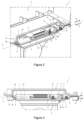
figure 2 est une vue en coupe et en perspective d'un système comprenant l'ensemble de verrouillage de lafigure 1 monté sur un premier et un deuxième élément ; et - La
figure 3 est une vue en coupe du système de lafigure 2 .
- There
figure 1 is an exploded view of an exemplary locking assembly according to one embodiment of the invention; - There
figure 2 is a sectional and perspective view of a system including the locking assembly of thefigure 1 mounted on a first and a second element; And - There
picture 3figure 2 .
Sur l'ensemble des figures, les éléments similaires portent des références identiques.In all the figures, similar elements bear identical references.
Dans la description qui suit, l'invention va plus particulièrement être décrite dans le cas du verrouillage d'un système de contrôle de véhicules comprenant un radar 2 de contrôle de véhicules et un trépied 3. Ceci n'est cependant pas limitatif, l'ensemble de verrouillage 1 de l'invention pouvant être mise en œuvre dans la fixation amovible de deux pièces quelconques.In the following description, the invention will more particularly be described in the case of the locking of a vehicle control system comprising a
L'ensemble de verrouillage 1 comprend une première platine 4 et une deuxième platine 5 configurées pour être montées respectivement sur le trépied 3 et le radar de contrôle de véhicules 2.The locking assembly 1 comprises a
Chaque platine 4, 5 comprend une première face, ou face supérieure, et une deuxième face, ou face inférieure, la face supérieure 7 de la première platine 4 étant configurée pour être placée face à la face inférieure 6 de la deuxième platine 5.Each
Dans ce qui suit, l'invention sera décrite dans le cas où la première platine 4 est montée fixe sur le trépied 3 tandis que la deuxième platine 5 est montée fixe sur le radar 2. La première platine 4 sera donc appelée « platine inférieure 4 » et la deuxième platine 5 « platine supérieure 5 » pour simplifier la lecture. Ici encore, ceci n'est pas limitatif, la première platine 4 pouvant être fixée sur le radar 2 et se trouver sous la deuxième platine 5 qui serait alors fixée sur le trépied 3.In what follows, the invention will be described in the case where the
Afin de faciliter le montage du radar 2, qui est lourd et encombrant, sur le trépied 3, la platine supérieure 5 et la platine inférieure 4 peuvent être sensiblement planes. Elles peuvent notamment comprendre chacune une tôle métallique, qui sont réalisées dans tout matériau adapté tel que de l'aluminium ou de l'acier.In order to facilitate the mounting of the
L'ensemble de verrouillage 1 comprend en outre une butée 8 configurée pour bloquer en translation la première platine 4 par rapport à la deuxième platine 5 suivant un premier sens A le long d'une direction de verrouillage X, ainsi qu'un verrou 9 mobile en translation le long de la direction de verrouillage X et qui est configuré pour bloquer en translation la platine supérieure 5 par rapport à la platine inférieure 4 dans un deuxième sens B qui est opposé au premier sens A. Le simple actionnement du verrou 9 permet ainsi de verrouiller ou déverrouiller la platine supérieure 5 sur la platine inférieure 4, selon le sens de translation choisi le long de la direction de verrouillage X.The locking assembly 1 further comprises an
Dans une forme de réalisation, le verrou 9 comprend une gâche 10, une attache 11 et un logement 12 configuré pour recevoir l'attache 11.In one embodiment, the
La gâche 10 est montée sur l'une parmi la platine supérieure 5 ou la platine inférieure 4. Par exemple, dans l'exemple illustré sur les figures, la gâche 10 est montée sur la face supérieure 7 de la platine supérieure 5, qui comprend alors un passage traversant 13 permettant de dévoiler en partie la gâche 10 et de permettre la coopération de l'attache 11 avec le logement 12. En variante, la gâche 10 pourrait être montée sur la face inférieure 6 de la platine supérieure 5. Comme nous le verrons par la suite, le montage de la gâche 10 sur la platine située au-dessus (ici, la platine supérieure) présente l'avantage d'être plus ergonomique pour l'opérateur.The
La gâche 10 est par ailleurs mobile en translation le long de la direction de verrouillage X entre une configuration de verrouillage et une configuration de déverrouillage. Pour cela, la gâche 10 peut par exemple être montée sur la platine supérieure 5 par l'intermédiaire d'une liaison glissière 14. La liaison glissière 14 peut typiquement comprendre au moins un rail formé dans la platine supérieure 5 et une série de boulons. De manière connue en soi, chaque boulon comprend une vis et un écrou, la tête de la vis étant placée dans le rail tandis que sa tige est insérée dans des trous correspondants formés dans la gâche 10 et fixée sur la gâche 10 à l'aide de l'écrou correspondant. Le cas échéant, afin de faciliter le serrage de la gâche 10 sur la platine supérieure 5 tout en garantissant son coulissement relatif, des rondelles (ou entretoises 15) sont emmanchées sur la tige des boulons et logées au sein des trous de la gâche 10. De préférence, les entretoises 15 présentent une épaisseur supérieure à celle de la gâche 10 afin de faciliter le serrage des boulons.The
La gâche 10 peut comprendre une poignée 16 afin de faciliter les manipulations du verrou 9 par l'opérateur. Cette poignée 16 est de préférence placée à proximité d'un bord de la gâche 10 afin d'être aisément accessible par l'opérateur.
Avantageusement, la poignée 16 est orientée perpendiculairement à la direction de verrouillage X afin de faciliter l'actionnement du mécanisme par l'opérateurAdvantageously, the
L'attache 11 est fixée sur l'une parmi la face supérieure 7 de la platine inférieure 4 et la gâche 10 tandis que le logement 12 est formé dans l'autre parmi la face supérieure 7 de la platine inférieure 4 et la gâche 10 et est configurée pour recevoir l'attache 11.The
Dans une première forme de réalisation, qui est visible ici sur les
La gâche 10 étant ici placée contre la face supérieure 7 de la platine supérieure 5, le logement 12 s'étend en outre dans le prolongement du passage traversant 13 formé dans la platine supérieure 5 afin de pouvoir recevoir l'attache 11.The
Une rainure de blocage 18 est formée dans la face de l'attache 11 qui est opposée à la butée 8. Ainsi, lorsque l'attache 11 est introduite dans le logement 12 et que la gâche 10 est amenée en configuration de verrouillage, la bordure 17 du logement 12 est insérée dans la rainure de blocage 18 de l'attache 11 et bloque en translation la gâche 10 par rapport aux platines 4, 5 suivant le deuxième sens B. La bordure 17 étant introduite dans la rainure de blocage 18, il n'est alors pas possible de sortir l'attache 11 du logement 12, la face supérieure 7 de la gâche 10 étant plaquée contre la face en regard de la rainure de blocage 18. La rainure de blocage 18 permet donc également de bloquer en translation la platine supérieure 5 par rapport à la platine inférieure 4 suivant une direction normale à la face supérieure 7 de la première platine 4. En revanche, lorsque la gâche 10 est amenée dans sa configuration de déverrouillage, la bordure 17 du logement 12 est libérée de la rainure de blocage 18 de l'attache 11, ce qui permet de sortir l'attache 11 du logement 12 et de séparer les deux platines 4, 5.A locking
Pour faciliter l'insertion à l'aveugle de l'attache 11 dans le logement 12, l'attache 11 comprend un chanfrein 19 permettant à la bordure 17 du logement 12 de glisser le long de l'attache 11 jusqu'à la rainure de blocage 18. A cet effet, la rainure de blocage 18 est formée dans la base 20b du chanfrein 19 (à proximité de la platine inférieure 4), et le chanfrein 19 est conformé de sorte à converger de la base 20b de l'attache 11, à proximité de la rainure de blocage 18, en direction du logement 12. La surface du chanfrein 19 est donc inclinée et forme un angle aigu au niveau de son sommet 20a qui peut être compris entre 35° et 60°, de préférence entre 40° et 50°.To facilitate the blind insertion of the
De la sorte, lors de l'assemblage des deux platines 4, 5, la bordure 17 glisse sur la surface inclinée du chanfrein 19 de l'attache 11 jusqu'à atteindre la rainure de blocage 18. Il n'est donc pas nécessaire à l'opérateur de placer avec précision l'attache 11 en face du logement 12 puisque la bordure 17 du logement 12 est guidée par le chanfrein 19 vers la rainure de blocage 18.In this way, when assembling the two
Optionnellement, l'attache 11 peut présenter une section à la base 20b sensiblement carrée et comprendre des chanfreins latéraux 21 (visibles par exemple sur les
L'attache 11 et la gâche 10 sont de préférence réalisées dans des matériaux résistants à l'usure et au frottement, typiquement en acier inoxydable. L'attache 11 peut être réalisée dans le même matériau que la platine inférieure 4, auquel cas elle peut être monolithique avec la platine inférieure 4, ou réalisée dans un matériau distinct de la platine inférieure 4, par exemple pour des questions de coût ou de densité, auquel cas elle peut être rapportée et fixée sur la platine inférieure 4. Par exemple, l'attache 11 peut être fixée à la platine inférieure 4 à l'aide d'une vis 22. Le cas échéant, la tête de la vis peut être fraisée afin de ne pas faire saillie de la face inférieure 6 de la platine inférieure 4.The
Dans une deuxième forme de réalisation (non illustrée) qui est équivalente à la première, l'attache 11 est fixée sur la gâche 10 et fait saillie (le cas échéant, à travers le passage traversant 13 formé dans la platine supérieure 5) en direction de la face supérieure 7 de la platine inférieure 4, tandis que le logement 12 est formé et débouche dans la face supérieure 7 de la platine inférieure 4.In a second embodiment (not shown) which is equivalent to the first, the
Afin de garantir le blocage de l'attache 11 dans le logement 12, la gâche 10 est raccordée à la platine supérieure 5 par l'intermédiaire d'un moyen de rappel 23 configuré pour ramener la gâche 10 vers sa configuration verrouillée. Le moyen de rappel 23 peut notamment comprendre un ressort 23 en traction.In order to guarantee the blocking of the
Le ressort 23 peut comprendre une première extrémité fixée sur la platine supérieure 5, de préférence sur la même face que la gâche 10, et une deuxième extrémité fixée sur la gâche 10. Le ressort 23 de rappel est aligné avec la direction de verrouillage X et est positionné sur la platine supérieure 5 de sorte à se trouver à l'opposé de la poignée 16.The
La raideur du ressort 23 est en outre choisie de sorte que, en l'absence d'efforts appliqués sur la gâche 10, le ressort 23 amène et maintient la gâche 10 dans sa configuration verrouillée et que, lorsqu'un opérateur applique un effort raisonnable sur la gâche 10, il puisse l'amener sans difficultés dans sa configuration déverrouillée. La raideur du ressort 23 peut par exemple être comprise entre 3 et 3.6 N/mm. De la sorte, lorsqu'un opérateur verrouille le radar 2 sur le trépied 3, il lui suffit de placer le sommet 20a de l'attache 11 face au logement 12 puis de laisser glisser le bord du logement 12 le long du chanfrein 19 de l'attache 11. Sous l'effet du poids du radar 2 auquel peut éventuellement être additionné un léger appui de la part de l'opérateur, le chanfrein 19 applique un effort sur la gâche 10 qui est opposé à l'effort de rappel du ressort 23 et le surpasse, ce qui déplace la gâche 10 vers sa configuration de déverrouillage. Avantageusement, l'opérateur n'a pas besoin de tirer sur la poignée 16 dans le deuxième sens suivant la direction de verrouillage X. Ainsi, l'opérateur peut tenir le radar 2, qui est très lourd et volumineux, avec ses deux mains. Lorsque la bordure 17 vient se loger dans la rainure de blocage 18, le chanfrein 19 n'offre plus de résistance à la gâche 10 : l'effort de rappel appliqué sur la gâche 10 par le ressort 23 a alors pour effet de l'amener automatiquement dans sa configuration verrouillée. Le cas échéant, l'entrée de la bordure 17 dans la rainure de blocage 18 peut générer un effet sonore (cliquètement) confirmant à l'opérateur la mise en prise de l'attache 11 et de la bordure 17. Le ressort 23 assure alors le maintien de la bordure 17 dans la rainure de blocage 18, ce qui limite les risques de sortie intempestive de l'attache 11 du logement 12, même lorsque le radar 2 est penché. Il suffit ensuite à un opérateur de libérer la bordure 17, par exemple en tirant sur la poignée 16 de la gâche 10, pour séparer les platines 4, 5.The stiffness of the
Dans une variante de réalisation, le moyen de rappel 23 peut comprendre un ressort de compression. Dans cette variante, le ressort 23 est alors placé du côté de la poignée 16 pour pouvoir amener et maintenir la gâche 10 dans sa configuration verrouillée. Le montage d'un ressort 23 en compression risque cependant d'être plus encombrant que le montage d'un ressort 23 en traction compte-tenu de la présence de la poignée 16.In a variant embodiment, the return means 23 may comprise a compression spring. In this variant, the
La butée 8 peut comprendre tout moyen permettant de mettre en butée axiale la platine supérieure 5 par rapport à la platine inférieure 4 le long de la direction de verrouillage X.The
Dans une forme de réalisation, la butée 8 peut par exemple comprendre une patte 24 s'étendant depuis la platine inférieure 4 qui est configurée pour être insérée dans une ouverture 25 formée dans la platine supérieure 5 et venir en appui contre une paroi 26 délimitant cette ouverture 25. La patte 24 peut par exemple comprendre une plaque s'étendant depuis la face supérieure 7 de la platine inférieure 4 en formant un angle obtus avec à celle-ci. Cette forme de réalisation permet ainsi de réaliser de manière très simple une butée 8, par exemple en pliant la platine inférieure 4 de sorte à obtenir la patte 24 inclinée et en réalisant, par exemple par laser, l'ouverture 25 dans la platine supérieure 5. Le cas échéant, la platine inférieure 4 peut être détourée afin de former des encoches 27 de part et d'autre du pli de la patte 24 et qui s'étendent depuis le pli en direction de la gâche 10. Les encoches 27 permettent alors de limiter les défauts et bavures lors du pliage de la patte 24 et, optionnellement, de venir en prise avec la paroi 26 de la platine supérieure 5. La patte 24 et la platine supérieure 5 sont alors monolithiques, ce qui simplifie la fabrication de l'ensemble de verrouillage 1.In one embodiment, the
Dans une variante de réalisation, la platine supérieure 5 peut comprendre un rebord 28 qui s'étend depuis la paroi 26 délimitant l'ouverture 25 formée dans la platine supérieure 5. Le rebord 28 s'étend sensiblement parallèlement à la patte 24. De la sorte, lorsque la patte 24 est introduite dans l'ouverture 25 formée dans la platine supérieure 5, sa surface inférieure vient en contact surfacique avec la surface inférieure du rebord 28, lorsque la platine supérieure 5 est verrouillée par rapport à la platine inférieure 4. Ainsi, lorsque la patte 24 est en contact surfacique avec le rebord 28, la face inférieure 6 de la platine supérieure 5 et la face supérieure 7 de la platine inférieure 4 sont en contact surfacique alors que c'est la surface inférieure de la patte 24 (dans le prolongement de la face opposée à la face supérieure 7) qui est en contact surfacique avec la surface inférieure du rebord 28 (dans le prolongement de la face opposée à la face inférieure 6). Les faces des platines 4, 5 qui sont en contact surfacique sur les parties de patte 24 et de rebord 28 sont opposées aux faces 6, 7 des platines 4, 5 qui sont en contact sur les parties principales plan. Les parties en contact sur une face d'une platine, sont en contact sur l'autre face au niveau de la patte 24 et du rebord 28.In a variant embodiment, the
Avantageusement, la patte 24 et le rebord 28 sont inclinés par rapport aux faces 6, 7 de la platine 4, 5 correspondante. La patte 24 et le rebord 28 peuvent par exemple former un angle compris entre 100° et 150°, de préférence entre 120° et 140°, avec la platine 5, 4 correspondante.Advantageously, the
L'agencement particulier de la patte 24 par rapport au rebord 28 ainsi que leur inclinaison par rapport aux platines 5, 4 permet, lorsque la patte 24 et le rebord 28 sont en contact surfacique, que la platine supérieure 5 soit bloquée en translation par rapport à la inférieure platine 4 le long de la direction de verrouillage X et suivant la direction normale à la face supérieure 7 de la platine inférieure 4.The particular arrangement of
La patte 24 et le rebord 28 peuvent en outre être monolithiques avec la platine correspondante. La patte 24 et le rebord 28 sont par exemple obtenues par pliage de la platine 4, 5 correspondante.The
De préférence, la patte 24 et le rebord 28 s'étendent depuis le bord de la platine 5, 4 correspondante qui est opposé au verrou 9. Cette configuration permet en effet d'améliorer l'engagement du verrou 9 et de la butée 8 (qui appliquent des efforts en sens contraire aux platines 4, 5) ainsi que l'ergonomie de l'ensemble de verrouillage 1.Preferably, the
L'ouverture 25 est délimitée par deux bords longitudinaux 251a, 251b orientés selon la direction de verrouillage X. Ces bords longitudinaux 251a, 251b peuvent le cas échéant former des guides pour un glissement en translation de la patte 24 au sein de l'ouverture 25 jusqu'à la paroi 26 et/ou le rebord 28.The
Ainsi, une longueur des bords longitudinaux 251a, 251b de l'ouverture 25 selon la direction de verrouillage est au moins égale à deux centimètres, de préférence au moins égale à cinq centimètres, afin de simplifier l'insertion à l'aveugle de la patte 24 dans l'ouverture 25 puis son glissement au sein de l'ouverture le long des deux guides formés par lesdits bords longitudinaux 251a, 251b.Thus, a length of the
Dans une autre forme de réalisation (non illustrée sur les figures), la butée 8 comprend un ou plusieurs plots s'étendant depuis l'une parmi la face inférieure 6 de la platine supérieure 5 et la face supérieure 7 de la platine inférieure 4 et autant de trous formés dans l'autre parmi la face inférieure 6 de la platine supérieure 5 et la face supérieure 7 de la platine inférieure 4 configurés pour recevoir un plot correspondant.In another embodiment (not illustrated in the figures), the
Quelle que soit la forme de réalisation de la butée 8, le ressort 23 en traction, la gâche 10 et le cas échéant la poignée 16 sont alignés, de préférence successivement, le long de la direction de verrouillage X. Cette configuration permet en effet d'éviter que les platines 4, 5 ne pivotent l'une par rapport à l'autre lorsque l'attache 11 est verrouillée dans le logement 12 et que les platines 4, 5 sont en butée. Elle rend en outre l'ensemble de verrouillage 1 particulièrement ergonomique et facile à mettre en prise pour l'opérateur.Whatever the embodiment of the
Les platines 4, 5 peuvent être montées sur tout élément, et en particulier tout radar 2 et tout trépied 3.The
Afin de rendre les platines 4, 5 universelles, une série de perçages 30 peut être prévue afin de permettre la fixation de chaque platine 4, 5 sur l'élément 2, 3 correspondant à l'aide de vis. De préférence, chaque platine 4, 5 comprend au moins quatre perçages 30. Optionnellement, un plus grand nombre de perçages 30 peut être prévu afin de permettre l'adaptation des platines 4, 5 sur un plus grand nombre de radars 2 et de trépieds 3.In order to make the
Le verrouillage de l'ensemble 1 peut être réalisé comme suit, par exemple dans le cas du verrouillage d'un radar 2 sur un trépied 3.The locking of the assembly 1 can be carried out as follows, for example in the case of the locking of a
Le trépied 3 est placé de préférence debout (verticalement) sur le sol. La platine inférieure 4 est fixée au sommet 20a du trépied 3 et s'étend parallèlement au sol (horizontalement). La platine supérieure 5 est fixée sur la face inférieure du radar 2. Le cas échéant, la face inférieure du radar 2 peut être aménagée afin de permettre la fixation de la platine supérieure 5 et l'insertion de l'attache 11 dans le logement 12. Par exemple, un renfoncement peut être formé dans la face inférieure du radar 2 afin de recevoir sans contact le ressort 23, la gâche 10 et l'attache 11.The
Les platines 4, 5 peuvent par exemple être fixées par vissage sur le radar 2 et le trépied 3.The
Pour verrouiller un radar 2 mobile comprenant une platine supérieure 5 sur un trépied 3 fixe comprenant une platine inférieure 4, l'opérateur met d'abord en butée les deux platines 4, 5, en particulier en positionnant le radar 2 de façon à ce que la patte 24 de la platine inférieure 4 soit placée dans l'ouverture 25 de la platine supérieure 5. Ensuite, l'opérateur fait glisser la platine supérieure 5 du radar 2 selon la direction de verrouillage X et le deuxième sens B jusqu'à ce que la patte 24 arrive en fin de course contre la paroi 26 de l'ouverture 25. Lorsque la platine supérieure 5 comprend un rebord 28, le glissement de la patte 24 au sein de l'ouverture 25 est effectué en direction du rebord 28. En fin de course au sein de l'ouverture 25, la patte 24 et le rebord 28 sont en contact l'un contre l'autre.To lock a
La platine supérieure 5 se trouve alors en butée axiale contre la platine inférieure 4, ce qui bloque le radar 2 par rapport au trépied 3 suivant le deuxième sens B.The
L'opérateur fait ensuite pivoter le radar 2 autour de la patte 24 de sorte à rapprocher les platines 4, 5 l'une de l'autre. En particulier, le radar 2 pivote autour de la surface de contact de la patte 24 et du rebord 28. Ce mouvement permet de placer l'attache 11 dans le logement 12. La bordure 17 du logement 12 glisse le long du chanfrein 19 de l'attache 11 jusqu'à atteindre la rainure de blocage 18. Ce mouvement a pour effet de surmonter l'effort appliqué par le ressort 23 sur la gâche 10 et de translater la gâche 10 par rapport à la platine supérieure 5, grâce notamment au poids appliqué par le radar 2 sur l'attache 11. Une fois que la bordure 17 atteint la rainure de blocage 18, l'effort appliqué par le ressort 23 a pour effet de ramener la gâche 10 (suivant le premier sens A) contre l'attache 11, sous la rainure de blocage 18. Un effet sonore peut être généré (cliquètement), confirmant ainsi le verrouillage de du radar 2 sur le trépied 3 (c'est à dire le verrouillage de l'ensemble 1).The operator then pivots the
La face supérieure 7 de l'attache 11 se trouve en butée contre la face supérieure 7 de la gâche 10 et est maintenue dans cette position par le ressort 23, ce qui empêche toute séparation intempestive des platines 4, 5.The
Pour déverrouiller l'ensemble 1, l'opérateur tire sur la poignée 16 dans le deuxième sens B, libérant ainsi à la bordure 17 du logement 12 de la rainure de blocage 18 de l'attaque 11. Ensuite, en maintenant la poignée tirée, l'opérateur fait pivoter le radar 2 autour de la patte 24 de sorte à éloigner les platines 4, 5 l'une de l'autre. En particulier, le radar 2 pivote autour de la surface de contact de la patte 24 et du rebord 28. Cela permet de faire sortir l'attache 11 du logement 12. Une fois l'attache 11 sortie du logement 12, l'opérateur fait glisser la platine supérieure 5 pour éloigner la paroi 26 et le cas échéant le rebord 28 de la patte 24 selon la direction de verrouillage X et le premier sens A. Ensuite, l'opérateur soulève le radar 2 pour dégager la patte 24 de l'ouverture 25 formée dans la platine supérieure 5.To unlock the assembly 1, the operator pulls on the
A titre indicatif, un radar de contrôle de véhicules 2 peut peser jusqu'à 10 kg et est généralement fixé à l'aveugle sur un trépied 3 à 1,60 m de hauteur. L'ensemble de verrouillage 1 permet ainsi de rendre la fixation amovible du radar 2, qui est lourd, sur le trépied 3, qui est relativement haut, de manière simple, rapide et ergonomique.As an indication, a
Claims (10)
Applications Claiming Priority (1)
| Application Number | Priority Date | Filing Date | Title |
|---|---|---|---|
| FR2109644A FR3127004B1 (en) | 2021-09-14 | 2021-09-14 | Locking assembly |
Publications (1)
| Publication Number | Publication Date |
|---|---|
| EP4148317A1 true EP4148317A1 (en) | 2023-03-15 |
Family
ID=78212299
Family Applications (1)
| Application Number | Title | Priority Date | Filing Date |
|---|---|---|---|
| EP22194784.9A Pending EP4148317A1 (en) | 2021-09-14 | 2022-09-09 | Latch assembly |
Country Status (4)
| Country | Link |
|---|---|
| US (1) | US12104632B2 (en) |
| EP (1) | EP4148317A1 (en) |
| AU (1) | AU2022231704A1 (en) |
| FR (1) | FR3127004B1 (en) |
Citations (2)
| Publication number | Priority date | Publication date | Assignee | Title |
|---|---|---|---|---|
| US9907416B1 (en) * | 2016-10-14 | 2018-03-06 | Steven R. Taylor | Devices for removably mounting an interface device |
| US20180224539A1 (en) * | 2017-02-07 | 2018-08-09 | Olivier Pouille | Portable enclosed speed limit radar |
Family Cites Families (6)
| Publication number | Priority date | Publication date | Assignee | Title |
|---|---|---|---|---|
| JPH0543571Y2 (en) * | 1988-09-30 | 1993-11-02 | ||
| EP1632680A1 (en) * | 2004-09-07 | 2006-03-08 | Fiberline A/S | A method of joining two profiled pultruded panels together and an arresting fitting therefor |
| US7273203B2 (en) * | 2005-02-23 | 2007-09-25 | Carnevali Jeffrey D | Locking device support |
| JP5002688B2 (en) * | 2010-07-12 | 2012-08-15 | 本田技研工業株式会社 | Housing mounting structure |
| US9135957B2 (en) * | 2011-03-03 | 2015-09-15 | Hewlett-Packard Development Company, L.P. | Electronic storage device mounts |
| US10660306B2 (en) * | 2017-07-31 | 2020-05-26 | Dylan Ernst | Device for securing feed or water bucket |
-
2021
- 2021-09-14 FR FR2109644A patent/FR3127004B1/en active Active
-
2022
- 2022-09-09 EP EP22194784.9A patent/EP4148317A1/en active Pending
- 2022-09-13 US US17/943,408 patent/US12104632B2/en active Active
- 2022-09-14 AU AU2022231704A patent/AU2022231704A1/en active Pending
Patent Citations (2)
| Publication number | Priority date | Publication date | Assignee | Title |
|---|---|---|---|---|
| US9907416B1 (en) * | 2016-10-14 | 2018-03-06 | Steven R. Taylor | Devices for removably mounting an interface device |
| US20180224539A1 (en) * | 2017-02-07 | 2018-08-09 | Olivier Pouille | Portable enclosed speed limit radar |
Also Published As
| Publication number | Publication date |
|---|---|
| AU2022231704A1 (en) | 2023-03-30 |
| FR3127004B1 (en) | 2024-09-13 |
| FR3127004A1 (en) | 2023-03-17 |
| US20230077656A1 (en) | 2023-03-16 |
| US12104632B2 (en) | 2024-10-01 |
Similar Documents
| Publication | Publication Date | Title |
|---|---|---|
| EP2451697B1 (en) | Device and method for adjusting the position between a front wing and a front door of a vehicle | |
| EP1178175A1 (en) | System for positioning and assembling a window pane on a window lifter | |
| EP2952975A1 (en) | Device for assembling a fitting circle in a watch middle | |
| FR3038505A1 (en) | REMOVABLE HANDLE | |
| EP2407620B1 (en) | Profiled upright for supporting a device which retains a pivoting door leaf by attraction and attraction supporting device including said upright | |
| FR2937071A1 (en) | Bonnet lock for motor vehicle, has fixation holes that are arranged in anterior face and/or posterior face and/or upper face of plate or in extensions of faces, where anterior face and posterior face are pierced with openings | |
| EP4148317A1 (en) | Latch assembly | |
| WO2021058894A1 (en) | Assembly part for connecting a dashboard to a body part of a vehicle | |
| FR2946156A1 (en) | HEAD VISUALIZATION DEVICE | |
| EP3360442B1 (en) | Arrangement system provided with an element and a counter-element | |
| EP1808557B1 (en) | Lock fitting | |
| FR3113559A3 (en) | Extension adjuster for tackle box and extension adjuster for foot tube | |
| EP4265868B1 (en) | Device for fixing a handle | |
| FR2735443A1 (en) | Anchoring lock for aircraft seat feet | |
| EP3902756B1 (en) | Embedded system for transporting goods | |
| EP1308588A1 (en) | Locking/unlocking device with multiple bolts for a sliding door | |
| EP2299039B1 (en) | Device for locking and unlocking a garage door or similar | |
| FR2825406A1 (en) | Hinged door panel for electric cabinet includes separable hinges forming pivots, or opening, enabling door to open on either side | |
| EP2834102A1 (en) | Unit for commanding the opening of a door from the inside | |
| EP4717634A1 (en) | Device for fixing a conveyor roller | |
| FR2908442A1 (en) | Edge fitting for e.g. door, has fixation unit with stop movable for fixing mounting plate on edge of opening for being displaced from free position towards locked position in which stop is housed and wedged between plate and stopper | |
| EP4091918A1 (en) | Handle for closing, in particular for side panel | |
| FR2952393A1 (en) | DEVICE FOR OPENING AND CLOSING A DOOR ON A FRAME | |
| FR3007055A1 (en) | DEVICE FOR TEMPORARILY CLOSING AN ELEMENT OPENING ON A SUPPORT ELEMENT | |
| FR3104187A1 (en) | Vehicle key including improved key box |
Legal Events
| Date | Code | Title | Description |
|---|---|---|---|
| PUAI | Public reference made under article 153(3) epc to a published international application that has entered the european phase |
Free format text: ORIGINAL CODE: 0009012 |
|
| STAA | Information on the status of an ep patent application or granted ep patent |
Free format text: STATUS: REQUEST FOR EXAMINATION WAS MADE |
|
| 17P | Request for examination filed |
Effective date: 20221104 |
|
| AK | Designated contracting states |
Kind code of ref document: A1 Designated state(s): AL AT BE BG CH CY CZ DE DK EE ES FI FR GB GR HR HU IE IS IT LI LT LU LV MC MK MT NL NO PL PT RO RS SE SI SK SM TR |
|
| P01 | Opt-out of the competence of the unified patent court (upc) registered |
Effective date: 20230919 |
|
| RAP1 | Party data changed (applicant data changed or rights of an application transferred) |
Owner name: IDEMIA ROAD SAFETY FRANCE |
|
| STAA | Information on the status of an ep patent application or granted ep patent |
Free format text: STATUS: EXAMINATION IS IN PROGRESS |
|
| 17Q | First examination report despatched |
Effective date: 20250612 |