EP4148149A1 - Heissgewalztes stahlblech und verfahren zur herstellung davon - Google Patents
Heissgewalztes stahlblech und verfahren zur herstellung davon Download PDFInfo
- Publication number
- EP4148149A1 EP4148149A1 EP21799825.1A EP21799825A EP4148149A1 EP 4148149 A1 EP4148149 A1 EP 4148149A1 EP 21799825 A EP21799825 A EP 21799825A EP 4148149 A1 EP4148149 A1 EP 4148149A1
- Authority
- EP
- European Patent Office
- Prior art keywords
- hot
- less
- steel sheet
- sheet thickness
- rolled steel
- Prior art date
- Legal status (The legal status is an assumption and is not a legal conclusion. Google has not performed a legal analysis and makes no representation as to the accuracy of the status listed.)
- Pending
Links
Images

Classifications
-
- C—CHEMISTRY; METALLURGY
- C21—METALLURGY OF IRON
- C21D—MODIFYING THE PHYSICAL STRUCTURE OF FERROUS METALS; GENERAL DEVICES FOR HEAT TREATMENT OF FERROUS OR NON-FERROUS METALS OR ALLOYS; MAKING METAL MALLEABLE, e.g. BY DECARBURISATION OR TEMPERING
- C21D9/00—Heat treatment, e.g. annealing, hardening, quenching or tempering, adapted for particular articles; Furnaces therefor
- C21D9/46—Heat treatment, e.g. annealing, hardening, quenching or tempering, adapted for particular articles; Furnaces therefor for sheet metals
-
- B—PERFORMING OPERATIONS; TRANSPORTING
- B22—CASTING; POWDER METALLURGY
- B22D—CASTING OF METALS; CASTING OF OTHER SUBSTANCES BY THE SAME PROCESSES OR DEVICES
- B22D11/00—Continuous casting of metals, i.e. casting in indefinite lengths
- B22D11/16—Controlling or regulating processes or operations
-
- B—PERFORMING OPERATIONS; TRANSPORTING
- B21—MECHANICAL METAL-WORKING WITHOUT ESSENTIALLY REMOVING MATERIAL; PUNCHING METAL
- B21C—MANUFACTURE OF METAL SHEETS, WIRE, RODS, TUBES, PROFILES OR LIKE SEMI-MANUFACTURED PRODUCTS OTHERWISE THAN BY ROLLING; AUXILIARY OPERATIONS USED IN CONNECTION WITH METAL-WORKING WITHOUT ESSENTIALLY REMOVING MATERIAL
- B21C47/00—Winding-up, coiling or winding-off metal wire, metal band or other flexible metal material characterised by features relevant to metal processing only
- B21C47/02—Winding-up or coiling
-
- C—CHEMISTRY; METALLURGY
- C21—METALLURGY OF IRON
- C21D—MODIFYING THE PHYSICAL STRUCTURE OF FERROUS METALS; GENERAL DEVICES FOR HEAT TREATMENT OF FERROUS OR NON-FERROUS METALS OR ALLOYS; MAKING METAL MALLEABLE, e.g. BY DECARBURISATION OR TEMPERING
- C21D1/00—General methods or devices for heat treatment, e.g. annealing, hardening, quenching or tempering
- C21D1/02—Hardening articles or materials formed by forging or rolling, with no further heating beyond that required for the formation
-
- C—CHEMISTRY; METALLURGY
- C21—METALLURGY OF IRON
- C21D—MODIFYING THE PHYSICAL STRUCTURE OF FERROUS METALS; GENERAL DEVICES FOR HEAT TREATMENT OF FERROUS OR NON-FERROUS METALS OR ALLOYS; MAKING METAL MALLEABLE, e.g. BY DECARBURISATION OR TEMPERING
- C21D8/00—Modifying the physical properties of ferrous metals or ferrous alloys by deformation combined with, or followed by, heat treatment
- C21D8/02—Modifying the physical properties of ferrous metals or ferrous alloys by deformation combined with, or followed by, heat treatment during manufacturing of plates or strips
- C21D8/021—Modifying the physical properties of ferrous metals or ferrous alloys by deformation combined with, or followed by, heat treatment during manufacturing of plates or strips involving particular fabrication steps or treatments of ingots or slabs
-
- C—CHEMISTRY; METALLURGY
- C21—METALLURGY OF IRON
- C21D—MODIFYING THE PHYSICAL STRUCTURE OF FERROUS METALS; GENERAL DEVICES FOR HEAT TREATMENT OF FERROUS OR NON-FERROUS METALS OR ALLOYS; MAKING METAL MALLEABLE, e.g. BY DECARBURISATION OR TEMPERING
- C21D8/00—Modifying the physical properties of ferrous metals or ferrous alloys by deformation combined with, or followed by, heat treatment
- C21D8/02—Modifying the physical properties of ferrous metals or ferrous alloys by deformation combined with, or followed by, heat treatment during manufacturing of plates or strips
- C21D8/0221—Modifying the physical properties of ferrous metals or ferrous alloys by deformation combined with, or followed by, heat treatment during manufacturing of plates or strips characterised by the working steps
- C21D8/0226—Hot rolling
-
- C—CHEMISTRY; METALLURGY
- C21—METALLURGY OF IRON
- C21D—MODIFYING THE PHYSICAL STRUCTURE OF FERROUS METALS; GENERAL DEVICES FOR HEAT TREATMENT OF FERROUS OR NON-FERROUS METALS OR ALLOYS; MAKING METAL MALLEABLE, e.g. BY DECARBURISATION OR TEMPERING
- C21D8/00—Modifying the physical properties of ferrous metals or ferrous alloys by deformation combined with, or followed by, heat treatment
- C21D8/02—Modifying the physical properties of ferrous metals or ferrous alloys by deformation combined with, or followed by, heat treatment during manufacturing of plates or strips
- C21D8/0221—Modifying the physical properties of ferrous metals or ferrous alloys by deformation combined with, or followed by, heat treatment during manufacturing of plates or strips characterised by the working steps
- C21D8/0236—Cold rolling
-
- C—CHEMISTRY; METALLURGY
- C21—METALLURGY OF IRON
- C21D—MODIFYING THE PHYSICAL STRUCTURE OF FERROUS METALS; GENERAL DEVICES FOR HEAT TREATMENT OF FERROUS OR NON-FERROUS METALS OR ALLOYS; MAKING METAL MALLEABLE, e.g. BY DECARBURISATION OR TEMPERING
- C21D8/00—Modifying the physical properties of ferrous metals or ferrous alloys by deformation combined with, or followed by, heat treatment
- C21D8/02—Modifying the physical properties of ferrous metals or ferrous alloys by deformation combined with, or followed by, heat treatment during manufacturing of plates or strips
- C21D8/0221—Modifying the physical properties of ferrous metals or ferrous alloys by deformation combined with, or followed by, heat treatment during manufacturing of plates or strips characterised by the working steps
- C21D8/0242—Flattening; Dressing; Flexing
-
- C—CHEMISTRY; METALLURGY
- C21—METALLURGY OF IRON
- C21D—MODIFYING THE PHYSICAL STRUCTURE OF FERROUS METALS; GENERAL DEVICES FOR HEAT TREATMENT OF FERROUS OR NON-FERROUS METALS OR ALLOYS; MAKING METAL MALLEABLE, e.g. BY DECARBURISATION OR TEMPERING
- C21D8/00—Modifying the physical properties of ferrous metals or ferrous alloys by deformation combined with, or followed by, heat treatment
- C21D8/02—Modifying the physical properties of ferrous metals or ferrous alloys by deformation combined with, or followed by, heat treatment during manufacturing of plates or strips
- C21D8/0247—Modifying the physical properties of ferrous metals or ferrous alloys by deformation combined with, or followed by, heat treatment during manufacturing of plates or strips characterised by the heat treatment
- C21D8/0263—Modifying the physical properties of ferrous metals or ferrous alloys by deformation combined with, or followed by, heat treatment during manufacturing of plates or strips characterised by the heat treatment following hot rolling
-
- C—CHEMISTRY; METALLURGY
- C22—METALLURGY; FERROUS OR NON-FERROUS ALLOYS; TREATMENT OF ALLOYS OR NON-FERROUS METALS
- C22C—ALLOYS
- C22C38/00—Ferrous alloys, e.g. steel alloys
- C22C38/001—Ferrous alloys, e.g. steel alloys containing N
-
- C—CHEMISTRY; METALLURGY
- C22—METALLURGY; FERROUS OR NON-FERROUS ALLOYS; TREATMENT OF ALLOYS OR NON-FERROUS METALS
- C22C—ALLOYS
- C22C38/00—Ferrous alloys, e.g. steel alloys
- C22C38/02—Ferrous alloys, e.g. steel alloys containing silicon
-
- C—CHEMISTRY; METALLURGY
- C22—METALLURGY; FERROUS OR NON-FERROUS ALLOYS; TREATMENT OF ALLOYS OR NON-FERROUS METALS
- C22C—ALLOYS
- C22C38/00—Ferrous alloys, e.g. steel alloys
- C22C38/04—Ferrous alloys, e.g. steel alloys containing manganese
-
- C—CHEMISTRY; METALLURGY
- C22—METALLURGY; FERROUS OR NON-FERROUS ALLOYS; TREATMENT OF ALLOYS OR NON-FERROUS METALS
- C22C—ALLOYS
- C22C38/00—Ferrous alloys, e.g. steel alloys
- C22C38/06—Ferrous alloys, e.g. steel alloys containing aluminium
-
- C—CHEMISTRY; METALLURGY
- C22—METALLURGY; FERROUS OR NON-FERROUS ALLOYS; TREATMENT OF ALLOYS OR NON-FERROUS METALS
- C22C—ALLOYS
- C22C38/00—Ferrous alloys, e.g. steel alloys
- C22C38/12—Ferrous alloys, e.g. steel alloys containing tungsten, tantalum, molybdenum, vanadium, or niobium
-
- C—CHEMISTRY; METALLURGY
- C22—METALLURGY; FERROUS OR NON-FERROUS ALLOYS; TREATMENT OF ALLOYS OR NON-FERROUS METALS
- C22C—ALLOYS
- C22C38/00—Ferrous alloys, e.g. steel alloys
- C22C38/14—Ferrous alloys, e.g. steel alloys containing titanium or zirconium
-
- C—CHEMISTRY; METALLURGY
- C22—METALLURGY; FERROUS OR NON-FERROUS ALLOYS; TREATMENT OF ALLOYS OR NON-FERROUS METALS
- C22C—ALLOYS
- C22C38/00—Ferrous alloys, e.g. steel alloys
- C22C38/18—Ferrous alloys, e.g. steel alloys containing chromium
- C22C38/22—Ferrous alloys, e.g. steel alloys containing chromium with molybdenum or tungsten
-
- C—CHEMISTRY; METALLURGY
- C22—METALLURGY; FERROUS OR NON-FERROUS ALLOYS; TREATMENT OF ALLOYS OR NON-FERROUS METALS
- C22C—ALLOYS
- C22C38/00—Ferrous alloys, e.g. steel alloys
- C22C38/18—Ferrous alloys, e.g. steel alloys containing chromium
- C22C38/24—Ferrous alloys, e.g. steel alloys containing chromium with vanadium
-
- C—CHEMISTRY; METALLURGY
- C22—METALLURGY; FERROUS OR NON-FERROUS ALLOYS; TREATMENT OF ALLOYS OR NON-FERROUS METALS
- C22C—ALLOYS
- C22C38/00—Ferrous alloys, e.g. steel alloys
- C22C38/18—Ferrous alloys, e.g. steel alloys containing chromium
- C22C38/26—Ferrous alloys, e.g. steel alloys containing chromium with niobium or tantalum
-
- C—CHEMISTRY; METALLURGY
- C22—METALLURGY; FERROUS OR NON-FERROUS ALLOYS; TREATMENT OF ALLOYS OR NON-FERROUS METALS
- C22C—ALLOYS
- C22C38/00—Ferrous alloys, e.g. steel alloys
- C22C38/18—Ferrous alloys, e.g. steel alloys containing chromium
- C22C38/28—Ferrous alloys, e.g. steel alloys containing chromium with titanium or zirconium
-
- C—CHEMISTRY; METALLURGY
- C22—METALLURGY; FERROUS OR NON-FERROUS ALLOYS; TREATMENT OF ALLOYS OR NON-FERROUS METALS
- C22C—ALLOYS
- C22C38/00—Ferrous alloys, e.g. steel alloys
- C22C38/18—Ferrous alloys, e.g. steel alloys containing chromium
- C22C38/32—Ferrous alloys, e.g. steel alloys containing chromium with boron
-
- C—CHEMISTRY; METALLURGY
- C22—METALLURGY; FERROUS OR NON-FERROUS ALLOYS; TREATMENT OF ALLOYS OR NON-FERROUS METALS
- C22C—ALLOYS
- C22C38/00—Ferrous alloys, e.g. steel alloys
- C22C38/18—Ferrous alloys, e.g. steel alloys containing chromium
- C22C38/34—Ferrous alloys, e.g. steel alloys containing chromium with more than 1.5% by weight of silicon
-
- C—CHEMISTRY; METALLURGY
- C22—METALLURGY; FERROUS OR NON-FERROUS ALLOYS; TREATMENT OF ALLOYS OR NON-FERROUS METALS
- C22C—ALLOYS
- C22C38/00—Ferrous alloys, e.g. steel alloys
- C22C38/18—Ferrous alloys, e.g. steel alloys containing chromium
- C22C38/38—Ferrous alloys, e.g. steel alloys containing chromium with more than 1.5% by weight of manganese
-
- B—PERFORMING OPERATIONS; TRANSPORTING
- B21—MECHANICAL METAL-WORKING WITHOUT ESSENTIALLY REMOVING MATERIAL; PUNCHING METAL
- B21C—MANUFACTURE OF METAL SHEETS, WIRE, RODS, TUBES, PROFILES OR LIKE SEMI-MANUFACTURED PRODUCTS OTHERWISE THAN BY ROLLING; AUXILIARY OPERATIONS USED IN CONNECTION WITH METAL-WORKING WITHOUT ESSENTIALLY REMOVING MATERIAL
- B21C47/00—Winding-up, coiling or winding-off metal wire, metal band or other flexible metal material characterised by features relevant to metal processing only
- B21C47/02—Winding-up or coiling
- B21C47/04—Winding-up or coiling on or in reels or drums, without using a moving guide
-
- C—CHEMISTRY; METALLURGY
- C21—METALLURGY OF IRON
- C21D—MODIFYING THE PHYSICAL STRUCTURE OF FERROUS METALS; GENERAL DEVICES FOR HEAT TREATMENT OF FERROUS OR NON-FERROUS METALS OR ALLOYS; MAKING METAL MALLEABLE, e.g. BY DECARBURISATION OR TEMPERING
- C21D2201/00—Treatment for obtaining particular effects
- C21D2201/05—Grain orientation
-
- C—CHEMISTRY; METALLURGY
- C21—METALLURGY OF IRON
- C21D—MODIFYING THE PHYSICAL STRUCTURE OF FERROUS METALS; GENERAL DEVICES FOR HEAT TREATMENT OF FERROUS OR NON-FERROUS METALS OR ALLOYS; MAKING METAL MALLEABLE, e.g. BY DECARBURISATION OR TEMPERING
- C21D2211/00—Microstructure comprising significant phases
- C21D2211/001—Austenite
-
- C—CHEMISTRY; METALLURGY
- C21—METALLURGY OF IRON
- C21D—MODIFYING THE PHYSICAL STRUCTURE OF FERROUS METALS; GENERAL DEVICES FOR HEAT TREATMENT OF FERROUS OR NON-FERROUS METALS OR ALLOYS; MAKING METAL MALLEABLE, e.g. BY DECARBURISATION OR TEMPERING
- C21D2211/00—Microstructure comprising significant phases
- C21D2211/002—Bainite
-
- C—CHEMISTRY; METALLURGY
- C21—METALLURGY OF IRON
- C21D—MODIFYING THE PHYSICAL STRUCTURE OF FERROUS METALS; GENERAL DEVICES FOR HEAT TREATMENT OF FERROUS OR NON-FERROUS METALS OR ALLOYS; MAKING METAL MALLEABLE, e.g. BY DECARBURISATION OR TEMPERING
- C21D2211/00—Microstructure comprising significant phases
- C21D2211/003—Cementite
-
- C—CHEMISTRY; METALLURGY
- C21—METALLURGY OF IRON
- C21D—MODIFYING THE PHYSICAL STRUCTURE OF FERROUS METALS; GENERAL DEVICES FOR HEAT TREATMENT OF FERROUS OR NON-FERROUS METALS OR ALLOYS; MAKING METAL MALLEABLE, e.g. BY DECARBURISATION OR TEMPERING
- C21D2211/00—Microstructure comprising significant phases
- C21D2211/005—Ferrite
-
- C—CHEMISTRY; METALLURGY
- C21—METALLURGY OF IRON
- C21D—MODIFYING THE PHYSICAL STRUCTURE OF FERROUS METALS; GENERAL DEVICES FOR HEAT TREATMENT OF FERROUS OR NON-FERROUS METALS OR ALLOYS; MAKING METAL MALLEABLE, e.g. BY DECARBURISATION OR TEMPERING
- C21D2211/00—Microstructure comprising significant phases
- C21D2211/008—Martensite
-
- C—CHEMISTRY; METALLURGY
- C21—METALLURGY OF IRON
- C21D—MODIFYING THE PHYSICAL STRUCTURE OF FERROUS METALS; GENERAL DEVICES FOR HEAT TREATMENT OF FERROUS OR NON-FERROUS METALS OR ALLOYS; MAKING METAL MALLEABLE, e.g. BY DECARBURISATION OR TEMPERING
- C21D2281/00—Making use of special physico-chemical means
- C21D2281/02—Making use of special physico-chemical means temperature gradient
Definitions
- the present invention relates to a hot-rolled steel sheet and a manufacturing method thereof.
- Patent Document 1 discloses a hot-rolled steel sheet in which, in a hot rolling step, the finish rolling temperature and the rolling reduction are set within predetermined ranges, thereby controlling the grain sizes and aspect ratios of prior austenite and reducing anisotropy.
- Patent Document 2 discloses a cold-rolled steel sheet in which, in a hot rolling step, the rolling reduction and the average strain rate are set within appropriate ranges in a predetermined finish rolling temperature range, thereby improving the toughness.
- each machine component In order to further reduce the weights of automobiles, each machine component, or the like, it is also expected to apply steel sheets having a sheet thickness premised on a cold-rolled steel sheet to automobile suspension components.
- the techniques described in Patent Document 1 and Patent Document 2 are effective in the manufacturing of automobile suspension components to which a high strength steel sheet is applied.
- the inventors investigated recessed parts that are formed at the inside bend in order to enable the provision of a steel sheet that is a high strength steel sheet and has improved in terms of a sharpened recessed part at an inside bend that is initiated during bending forming.
- the sharpened recessed part such as a fine crack at the inside bend (hereinafter, a sharpened recessed part such as a fine crack that is formed at a inside bend will be referred to as "inside bend recessed part”) is not a fine crack and is attributed to unevenness formed by the plastic buckling of the surface layer of the steel sheet toward the outside of the plane in a microscopic region during bending forming.
- the present inventors found that, in a case where the depth of an inside bend recessed part exceed a certain value, the fatigue properties of hot-rolled steel sheets significantly deteriorate.
- An object of the present invention is to provide a hot-rolled steel sheet having a high strength and excellent formability and enabling reduction in the depth of an inside bend recessed part that is formed during bending forming and a manufacturing method thereof.
- the present inventors found that the depth of an inside bend recessed part formed during bending forming can be reduced to an extent that component performance is not degraded by setting a chemical composition and a metallographic structure appropriate for obtaining a high strength and, furthermore, particularly controlling the rotation angle of a specific crystal orientation in the sheet thickness direction.
- a high strength in the present embodiment means that the tensile (maximum) strength is 880 MPa or more.
- excellent formability means that the hole expansion rate is 35% or more.
- the gist of the present invention made based on the above-described findings is as follows.
- a hot-rolled steel sheet according to the present embodiment (hereinafter, simply referred to as the steel sheet in some cases) will be described in detail.
- the present invention is not limited only to a configuration disclosed in the present embodiment and can be modified in a variety of manners within the scope of the gist of the present invention.
- the hot-rolled steel sheet according to the present embodiment contains, by mass%, C: 0.060% to 0.170%, Si: 0.030% to 1.700%, Mn: 1.20% to 3.00%, Al: 0.010% to 0.700%, Nb: 0.005% to 0.050%, P: 0.0800% or less, S: 0.0100% or less, N: 0.0050% or less, and a remainder of Fe and an impurity.
- C 0.060% to 0.170%
- Si 0.030% to 1.700%
- Mn 1.20% to 3.00%
- Al 0.010% to 0.700%
- Nb 0.005% to 0.050%
- P 0.0800% or less
- S 0.0100% or less
- N 0.0050% or less
- a remainder of Fe and an impurity a remainder of Fe and an impurity.
- C is one element that determines the strength of the hot-rolled steel sheet.
- the C content is set to 0.060% or more.
- the C content is preferably 0.080% or more.
- the C content is set to 0.170% or less.
- the C content is preferably 0.150% or less.
- Si is an element that improves the strength of the hot-rolled steel sheet by solid solution strengthening.
- Si is also an element that has an effect on suppressing the formation of a carbide and suppresses softening during a heat treatment.
- the Si content is set to 0.030% or more.
- the Si content is preferably 0.050% or more.
- the Si content is set to 1.700% or less. In order to further suppress softening during tempering, the Si content is preferably set to 1.300% or less.
- Mn is an element necessary to improve the strength of the hot-rolled steel sheet.
- the Mn content is set to 1.20% or more.
- the Mn content is preferably 1.50% or more.
- the Mn content exceeds 3.00%, the toughness of a cast slab deteriorates, and hot rolling is not possible. Therefore, the Mn content is set to 3.00% or less.
- the Mn content is preferably 2.70% or less.
- Al is an element that acts as a deoxidizing agent and improves the cleanliness of steel.
- the Al content is set to 0.010% or more.
- the Al content is preferably 0.100% or more.
- the Al content is set to 0.700% or less.
- Al is an oxidizing element, and the Al content is preferably 0.300% or less in order to obtain an effect on additional improvement in continuous castability and a cost reduction effect.
- the Nb content In order to obtain an average grain diameter of prior austenite grains of less than 30.00 ⁇ m in a hot rolling step, the Nb content needs to be set to 0.005% or more.
- the Nb content is set to 0.005% or more.
- the Nb content is preferably 0.010% or more or 0.020% or more.
- the Nb content is set to 0.050% or less.
- the Nb content is preferably 0.040% or less.
- P is an impurity element that is inevitably incorporated into the hot-rolled steel sheet in a manufacturing process of the hot-rolled steel sheet.
- a P content of up to 0.0800% is acceptable. Therefore, the P content is set to 0.0800% or less.
- the P content is preferably 0.0500% or less.
- the S content is set to 0.0100% or less.
- the S content is preferably 0.0080% or less.
- N is an impurity element that is inevitably incorporated into the hot-rolled steel sheet in the manufacturing process of the hot-rolled steel sheet.
- the N content becomes more than 0.0050%, the amount of residual austenite in the hot-rolled steel sheet increases, and there are cases where the hole expansibility of the hot-rolled steel sheet deteriorates and the slab toughness deteriorates. Therefore, the N content is set to 0.0050% or less.
- the N content is preferably 0.0040% or less.
- the N content is reduced to less than 0.0001%, the steelmaking cost significantly increases, and thus the N content may be set to 0.0001% or more.
- the remainder of the chemical composition of the hot-rolled steel sheet according to the present embodiment may be Fe and an impurity.
- the impurity means a substance that is incorporated from ore as a raw material, a scrap, a manufacturing environment, or the like and is allowed to an extent that the hot-rolled steel sheet according to the present embodiment is not adversely affected.
- the hot-rolled steel sheet according to the present embodiment may contain one or more of the group consisting of Ti, Mo, V, Cr, and B as an arbitrary element instead of some of Fe.
- the lower limit of the content is 0%.
- Ti is an element that increases the strength of the hot-rolled steel sheet by being precipitated as a fine carbide in steel and thus may be contained.
- the Ti content is preferably set to 0.0200% or more.
- the Ti content is preferably set to 0.1800% or less.
- Mo is an element that enhances the hardenability of steel and may be contained as an element that adjusts the strength of the hot-rolled steel sheet.
- the Mo content is preferably set to 0.030% or more.
- the Mo content is preferably set to 0.150% or less.
- V 0% to 0.3000%
- V is an element that develops an effect similar to that of Ti.
- the V content is preferably set to 0.0500% or more.
- the V content is preferably set to 0.3000% or less.
- the Cr content is an element that develops an effect similar to that of Mn.
- the Cr content is preferably set to 0.050% or more.
- the Cr content is preferably set to 0.500% or less.
- B is an element that develops an effect similar to that of Mo and is an element that has an effect on improvement in hardenability and increases the strength of the hot-rolled steel sheet.
- the B content is preferably set to 0.0001% or more.
- the B content is preferably set to 0.0030% or less.
- the above-described chemical composition of the hot-rolled steel sheet may be analyzed using a spark discharge emission spectrophotometer or the like.
- C and S values identified by combusting the hot-rolled steel sheet in an oxygen stream using a gas component analyzer or the like and measuring C and S by an infrared absorption method are adopted.
- N a value identified by melting a test piece collected from the hot-rolled steel sheet in a helium stream and measuring N by a thermal conductivity method is adopted.
- the metallographic structure of the hot-rolled steel sheet according to the present embodiment will be described.
- the characteristics of the metallographic structure are limited to an extent that not only an effect on improvement in the strength and formability of the hot-rolled steel sheet but also an effect on reduction in the depths of inside bend recessed parts can be obtained.
- vol%, bainite and martensite are a total of 80.0% or more, ferrite is 20.0% or less, cementite and residual austenite are a total of 0% to 10.0%
- the average grain diameter of prior austenite grains is less than 30.00 ⁇ m a region, where the rotation angle between the normal line of the surface and a (011) pole near the normal line becomes 5° or less, is 0.150 or less from the surface in terms of the sheet thickness direction position standardized by the sheet thickness, a region, where the rotation angle between the normal line of the surface and the (011) pole near the normal line becomes 20° or more, is 0.250 or more from the surface in terms of the sheet thickness direction position standardized by the sheet thickness
- Bainite and martensite Total of 80.0% or more
- the volume percentage of bainite and martensite is set to a total of 80.0% or more.
- the volume percentage of the bainite and the martensite is preferably 83.0% or more.
- the martensite may be tempered, and the martensite may contain cementite and residual austenite.
- the volume percentage of the cementite and the residual austenite may be set to a total of 10.0% or less.
- the volume percentage of the ferrite is set to 20.0% or less.
- the volume percentage of the ferrite is preferably 17.0% or less and more preferably 15.0% or less.
- the volume percentage of the ferrite may be set to 10.0% or more from the viewpoint of ensuring hole expansibility.
- the volume percentage of the cementite and the residual austenite is set to 10.0% or less.
- the volume percentage of the cementite and the residual austenite is preferably 7.0% or less and more preferably 5.0% or less.
- the volume percentage of the cementite and the residual austenite is preferably as small as possible, and thus the lower limit is 0%.
- the volume percentage of the ferrite As the volume percentage of the ferrite, the area ratio of crystal grains in which an iron-based carbide is not formed, which are obtained by observing the structure on a metallographic structure photograph, is used. A sample is collected such that a sheet thickness cross section that intersects the rolling direction of the hot-rolled steel sheet at right angles can be observed, the cross section is corroded using a nital etching solution having a concentration of 3% to 5% to make the ferrite visible, and the structure is observed using metallographic structure photographs each captured at a magnification of 500 to 1000 times at the 1/4 position in the sheet thickness direction from the surface of the hot-rolled steel sheet and at the 1/2 position in the sheet thickness direction from the surface.
- the metallographic structure photographs are prepared at 3 or more visual fields in each of the 1/4 position in the sheet thickness direction from the surface and the 1/2 position in the sheet thickness direction from the surface.
- the area ratio of the ferrite that is observed in each metallographic structure photograph is obtained, and the average value thereof is calculated, thereby obtaining the volume percentage of the ferrite.
- the iron-based carbide is recognized as black granular contrast having a circle equivalent diameter of 1 ⁇ m or less in the metallographic structure photograph and is observed in the crystal grain.
- the total of the volume percentages of the bainite and the martensite in the present embodiment a value obtained by subtracting the volume percentage of the ferrite and the total of the volume percentages of the cementite and the residual austenite that are measured by a method to be described below from 100.0% is used.
- the volume percentage of the residual austenite is measured by EBSP.
- Analysis by EBSP is performed using a sample collected from the same position as the sample collection position at the time of measuring the volume percentage of the ferrite at the 1/4 position in the sheet thickness direction from the surface of the hot-rolled steel sheet and at the 1/2 position in the sheet thickness direction from the surface.
- the sample needs to be polished using silicon carbide paper #600 to #1500, then, finished into a mirror surface using a liquid containing a diamond powder having grain sizes of 1 to 6 ⁇ m dispersed in a diluted solution such as an alcohol or pure water, and then finished by electrolytic polishing for the purpose of sufficiently removing strain in a cross section to be measured.
- the sample in order to remove mechanical polishing strain on an observed section, the sample needs to be polished a minimum of 20 ⁇ m and polished a maximum of 50 ⁇ m.
- the sample is preferably polished 30 ⁇ m or less in consideration of rollover at the end portion.
- the accelerating voltage is set to 15 to 25 kV, the measurement is performed at intervals of at least 0.25 ⁇ m or less, and the crystal orientation information at each measurement point in a range that is 150 ⁇ m or more in the sheet thickness direction and 250 ⁇ m or more in a rolling direction is obtained.
- grains having an fcc crystal structure are determined as the residual austenite using a "Phase Map" function installed in software "OIM Analysis (registered trademark)" included in an EBSP analyzer.
- the ratio of measurement points determined as the residual austenite is obtained, thereby obtaining the area ratio of the residual austenite.
- the obtained area ratio of the residual austenite is regarded as the volume percentage of the residual austenite.
- the measurement intervals are narrow and the measurement range is wide.
- the measurement intervals are set to 0.01 ⁇ m or more.
- the measurement range needs to be set to 200 ⁇ m in the sheet thickness direction and 400 ⁇ m in the sheet width direction at a maximum.
- an instrument including a thermal field emission-type scanning electron microscope (JSM-7001F manufactured by JEOLLtd.) and an EBSD detector (DVC 5-type detector manufactured by TSL) is used. At this time, the degree of vacuum in the instrument is set to 9.6 ⁇ 10 -5 Pa or less, the irradiation current level is set to 13, and the irradiation level of the electron beam is set to 62.
- the volume percentage of the cementite is measured using a sample collected from the same position as the sample collection position at the time of measuring the volume percentage of the ferrite at the 1/4 position in the sheet thickness direction from the surface of the hot-rolled steel sheet and at the 1/2 position in the sheet thickness direction from the surface.
- the sheet thickness cross section is polished with abrasive paper or alumina abrasive grains to be finished into a mirror surface, then, corroded with a 3% nital solution and picral, and observed using a scanning electron microscope (SEM).
- a plurality of visual fields are captured using a photograph device attached to the SEM at a magnification of 2000 times such that the total observed visual field area becomes 1.6 ⁇ 10 7 ⁇ m 2 or more, and the area ratio of the cementite is measured using image analysis software such as particle analysis software. Therefore, the area ratio of the cementite is obtained.
- the obtained area ratio of the cementite is regarded as the volume percentage of the cementite.
- Average grain diameter of prior austenite grains Less than 30.00 ⁇ m
- the inside bend recessed part is caused by the plastic buckling of crystal grains in the surface layer of the hot-rolled steel sheet and is affected by the sizes of the structures of the bainite and the martensite, which have low deformability.
- the size of the prior austenite grain becomes the maximum unit (that is, there is no case where the bainite and the martensite become larger than the prior austenite grain).
- the bainite and the martensite are in a form of being divided into several structural units called blocks.
- the average grain diameter of the prior austenite grains which becomes the maximum size of the structural units of the bainite and the martensite, which are primary phases (volume percentage of 80.0% or more) of the hot-rolled steel sheet according to the present embodiment, is set to less than 30.00 ⁇ m.
- the average grain diameter of the prior austenite grains is preferably set to less than 20.00 ⁇ m.
- the average grain diameter of the prior austenite grains in the surface layer region is affected by the average grain diameter of the prior austenite grains in the surface layer region, it is in a surface layer region (a region from the surface of the hot-rolled steel sheet to a 100 ⁇ m position in the sheet thickness direction from the surface) that the average grain diameter of the prior austenite grains is set to less than 30.00 ⁇ m.
- a sample is collected such that a sheet thickness cross section that intersects the rolling direction of the hot-rolled steel sheet at right angles can be observed, and the sample is used after the structure on the sheet thickness cross section is made visible with a saturated aqueous solution of picric acid and an etching solution of sodium dodecylbenzene sulfonate.
- a surface layer region a region from the surface of the hot-rolled steel sheet to a 100 ⁇ m position in the sheet thickness direction from the surface
- the circle equivalent diameters of the prior austenite grains are measured using a structure photograph captured at a magnification of 500 times using a scanning electron microscope.
- the scanning electron microscope needs to be equipped with a two-electron detector.
- the sample is irradiated with an electron beam in a vacuum at 9.6 ⁇ 10 -5 Pa or less, an accelerating voltage of 15 kV, and an irradiation current level of 13, and a secondary electron image of the surface layer region (the region from the surface of the hot-rolled steel sheet to the 100 ⁇ m position in the sheet thickness direction from the surface) is captured.
- the number of visual fields captured is set to 10 or more visual fields.
- the prior austenite grain boundaries are captured as bright contrast.
- the circle equivalent diameter is calculated for one of the prior austenite grains that is included in the observed visual field.
- the above-described operation is performed on all of the prior austenite grains that are included in the observed visual field except for prior austenite grains that are not fully included in the captured visual field, such as prior austenite grains in the end portion of the captured visual field, and the circle equivalent diameters of all of the prior austenite grains in the captured visual field are obtained.
- the average grain diameter of the prior austenite grains is obtained by calculating the average value of the circle equivalent diameters of the prior austenite grains obtained in the individual captured visual fields.
- the present inventors found that, when a region where the rotation angle between the normal line of the surface of the hot-rolled steel sheet and the (011) pole near the normal line becomes 5° or less is made present at 0.150 or less from the surface in terms of the sheet thickness direction position standardized by the sheet thickness, and a region where the rotation angle becomes 20° or more is made present at 0.250 or more from the surface in terms of the sheet thickness direction position standardized by the sheet thickness, it is possible to reduce the depths of inside bend recessed parts in an arbitrary sheet surface direction.
- the sheet thickness direction position standardized by the sheet thickness is expressed as d/t where d represents the sheet thickness direction depth and t represents the sheet thickness.
- plastic buckling phenomenon As described above, inside bend recessed parts are attributed to a microscopic plastic buckling phenomenon in the surface layer of the hot-rolled steel sheet.
- the present inventors considered this plastic buckling phenomenon as a microscopic plastic flow and understood that the plastic buckling phenomenon results from a basic behavior that is caused by the rotation of crystal grains. In the case of bending distortion, the amount of crystal grains rotated depends on the distortion gradient from the neutral axis toward the sheet thickness surface.
- the present inventors considered that the distribution of orientation groups having different crystal rotation behaviors in the sheet thickness direction causes an imbalance in local distortion and promotes buckling on the surface layer of the hot-rolled steel sheet.
- the inventors paid attention to and investigated the relationship between the depths of inside bend recessed parts and crystal orientations in the sheet thickness direction.
- a typical crystal orientation a (011) pole is drawn in the sheet thickness direction and divided into a region where the rotation angle is 5° or less and the crystal orientation does not change and a region where the rotation angle is 20° or more and the crystal orientation does not change.
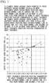
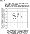
- the present inventors considered that the thickness in a range where the crystal orientation does not change causes distortion unevenness in the sheet thickness direction and investigated the relationship between the proportions of the depths in the sheet thickness direction in the individual ranges and the depths of inside bend recessed parts. As a result, as shown in FIG. 1 and FIG.
- FIG. 1 is a view obtained from an example to be described below and a view showing the relationship between the sheet thickness direction position standardized by the sheet thickness of the region where the rotation angle between the normal line of the surface of the steel sheet and the (011) pole near the normal line becomes 5° or less and the depth of the inside bend recessed part.
- FIG. 2 is a view obtained from an example to be described below and a view showing the relationship between the sheet thickness direction position standardized by the sheet thickness of the region where the rotation angle between the normal line of the surface and the (011) pole near the normal line becomes 20° or more and the depth of the inside bend recessed part.
- the present inventors found that, in order to reduce the depth of the inside bend recessed part, there is the most favorable range of the depth proportions of the region where the angle formed between the normal line of the surface of the hot-rolled steel sheet and the (011) pole becomes 5° or less and the region where the rotation angle becomes 20° or more. As shown in FIG.
- 3 is a view obtained from the example to be described below and a view showing the relationship among the sheet thickness direction position standardized by the sheet thickness of the region where the rotation angle between the normal line of the surface and the (011) pole near the normal line becomes 5° or less, the sheet thickness direction position standardized by the sheet thickness of the region where the rotation angle between the normal line of the surface and the (011) pole near the normal line becomes 20° or more, and the evaluation result of the inside bend recessed part in the example.
- Measurement is performed by EBSP using a sample having a cross section finished into a mirror surface by the same method as for the sample used for the measurement of the volume percentage of the prior austenite grains.
- the sample needs to be finished by electrolytic polishing for the purpose of sufficiently removing strain in the cross section to be measured.
- the sample in order to remove mechanical polishing strain on an observed section, the sample needs to be polished a minimum of 20 ⁇ m and polished a maximum of 50 ⁇ m.
- the sample is preferably polished 30 ⁇ m or less in consideration of rollover at the end portion.
- the accelerating voltage is set to 15 to 25 kV
- the measurement range is set to a measurement range that covers the overall sheet thickness.
- the measurement range needs to be 1000 ⁇ m or more in the rolling direction.
- the measurement intervals may be 5 ⁇ m or more.
- the measurement intervals are set to 30 ⁇ m or less in order to avoid an increase in the number of crystal grains that are not measured by mistake.
- Crystal orientation data need to be recorded along with the measurement coordinate system. From the obtained crystal orientation data, the rotation angle between the normal line of the surface of the steel sheet and the (011) pole near the normal line is measured by the following method.
- the rotation angle between the normal line of the surface of the hot-rolled steel sheet and the (011) pole near the normal line is a value that is measured by plotting the crystal orientation data obtained by the EBSP measurement on a positive pole figure.
- poles of the (011) orientation are displayed such that normal lines (origin: ND) become the normal lines to the sheet surface of the hot-rolled steel sheet, the horizontal axis TD becomes the sheet width direction, and the axis RD orthogonal to the horizontal axis becomes the rolling direction.
- the crystal orientation is a group of points measured at predetermined intervals in a measurement range that is 1000 ⁇ m or more in the rolling direction and covers the overall sheet thickness range.
- This group of points is divided into 20 sections in the sheet thickness direction, and a (011) pole figure is drawn.
- the angle between the origin ND (normal line of the surface of the hot-rolled steel sheet) and the nearest (011) pole is measured. This measurement value is defined as the rotation angle between the normal line of the surface and the (011) pole near the normal line.
- a value obtained by dividing each depth direction position by the sheet thickness is defined as the sheet thickness direction position (sheet thickness direction depth d/sheet thickness t) standardized by the sheet thickness, and the region where the rotation angle becomes 5° or less and the region where the rotation angle becomes 20° or more are obtained at this sheet thickness direction position standardized by the sheet thickness.
- the tensile strength is 880 MPa or more.
- the tensile strength may be 900 MPa or more.
- the tensile strength is preferably as high as possible, but may be 1500 MPa or less from the viewpoint of a weight reduction effect of the high-strengthening of the hot-rolled steel sheet.
- the tensile strength is measured by performing a tensile test in accordance with JIS Z 2241: 2011 using a No. 5 test piece of JIS Z 2241: 2011.
- a position where the tensile test piece is collected is the central position in the sheet width direction, and a direction perpendicular to the rolling direction is the longitudinal direction.
- the hole expansion rate is 35% or more.
- the hole expansion rate may be set to 50% or more in order to reduce the ironing rate of the burring portion and reduce the load on a die in a pressing step.
- the hole expansion rate may be set to 80% or more.
- the hole expansion rate is measured by performing a hole expansion test in accordance with JIS Z 2256: 2010.
- a casting step and a hot rolling step to be described below are important steps for controlling the crystal orientation distribution in the sheet thickness direction and the average grain diameter of the prior austenite grains, which are requirements necessary to reduce the depths of the inside bend recessed parts.
- the preferable manufacturing method of the hot-rolled steel sheet according to the present embodiment includes the following steps.
- the preferable manufacturing method of the hot-rolled steel sheet according to the present embodiment may further include a heat treatment step of, after the coiling, holding the hot-rolled steel sheet in a temperature range of 200°C or higher and lower than 450°C for 90 to 80000 seconds.
- the average surface temperature gradient in a region from the meniscus to 1.0 m from the meniscus is set to 300 to 650 °C/m.
- the surface temperature gradient in the early stage of solidification affects the rotation angle between the normal line of the surface of the hot-rolled steel sheet and the (011) pole near the normal line.
- the average surface temperature gradient refers to a temperature gradient obtained by dividing the temperature in a mold in contact with a solidified shell by the distance from the meniscus. The temperature is measured with thermocouples embedded in the mold.
- thermocouples are embedded at a 0 mm position below the meniscus that is 0.010 mm or less from the outer surface (solidified shell) of the mold and a 1.0 mm below the meniscus that is 0.010 mm or less from the outer surface (solidified shell) of the mold in the center portion of the long side surface of the slab in the width direction.
- the thermocouple that is embedded at the 0 mm position below the meniscus needs to be 0.040 mm or less and preferably needs to be 0.005 mm or less distant from the meniscus (in a casting direction).
- a value obtained by dividing each measured temperature by the section distance is regarded as the average surface temperature gradient.
- the region where the rotation angle between the normal line of the surface of the hot-rolled steel sheet and the (011) pole near the normal line is 5° or less is present at more than 0.150 from the surface in terms of the sheet thickness direction position standardized by the sheet thickness.
- the average temperature gradient in the above-described region is more than 650 °C/m, the region where the rotation angle between the normal line of the surface of the hot-rolled steel sheet and the (011) pole near the normal line is 20° or more is present at less than 0.250 from the surface in terms of the sheet thickness direction position standardized by the sheet thickness.
- the average surface temperature gradient in the region from the meniscus to 1.0 m from the meniscus is set to 300 to 650 °C/m, and the slab is manufactured.
- the lower limit of the average surface temperature gradient is preferably 350 °C/m or 400 °C/m, and the upper limit of the average surface temperature gradient is preferably 600 °C/m or 550 °C/m.
- the average casting velocity in the casting step may be in an ordinary range, may be 0.8 m/min or faster, or may be 1.2 m/min or faster. From the viewpoint of cost reduction, the average casting velocity in the casting step is preferably set to 1.2 m/min or faster.
- the average casting velocity is faster than 2.5 m/min, the cooling temperature gradient in the slab thickness direction increases due to the increase in the casting velocity, and the slab internal stress in a solidification process increases, which makes it easy for a defect to be initiated. Therefore, the average casting velocity is preferably 2.5 m/min or slower.
- the average casting velocity is 0.6 m/min or slower, the cooling temperature gradient in the slab thickness direction decreases, but the economic efficiency is significantly impaired. Therefore, the average casting velocity is preferably 0.6 to 2.5 m/min.
- the slab obtained by the continuous casting is heated such that the slab surface temperature becomes 1200°C or higher and is held in a temperature range of 1200°C or higher for 30 minutes or longer, thereby solutionizing the slab.
- the heating temperature is lower than 1200°C, homogenization and carbide dissolution by a solutionizing treatment does not proceed, and ferritic transformation proceeds, whereby the strength of the hot-rolled steel sheet decreases.
- the heating temperature is preferably set to 1230°C or higher in order to more reliably form a solid solution of Ti.
- the slab temperature before heating the slab may be cooled to room temperature or may remain at a high temperature after the continuous casting in a case where there is a concern of cracking caused by thermal stress or the like.
- the slab is heated in the heating step by charging the slab into a furnace controlled to a predetermined temperature, and a time taken for the slab surface temperature to become 1200°C or higher needs to be set to 30 minutes or longer, which is sufficient.
- a time taken for the slab surface temperature to become 1200°C or higher needs to be set to 30 minutes or longer, which is sufficient.
- the holding time is preferably 40 minutes or longer, 60 minutes or longer, or 100 minutes or longer.
- the heating temperature needs to be 1400°C or lower, and the heating time needs to be 300 minutes or shorter.
- the slab contains Ti
- a time for the slab surface temperature to becomes 1230°C or higher needs to be set to 60 minutes or longer, which is sufficient.
- the slab is disposed on an inorganic substance skid, and the slab may be solutionized by being heated to equal to or lower than a temperature at which the slab heated by a reaction between the inorganic substance and iron at this time does not dissolve.
- the finish rolling is performed such that the total rolling reduction within a temperature range of 870°C to 980°C becomes 80% or more.
- the total rolling reduction is preferably 85% or larger. In a case where the total rolling reduction within the temperature range of 870°C to 980°C is smaller than 80%, the average grain diameter of the austenite grains becomes 30.00 ⁇ m or more.
- the total rolling reduction mentioned herein is a value obtained by adding the rolling reduction at each rolling stand where the biting temperature becomes 870°C to 980°C.
- the finish rolling temperature is higher than 980°C, the average grain diameter of the austenite grains becomes large regardless of the total rolling reduction at the rolling stand, and it is not possible to control the depths of the inside bend recessed parts to less than 30.0 ⁇ m.
- the total rolling reduction within the temperature range of 870°C to 980°C may be set to 98% or less.
- the total rolling reduction at lower than 870°C is 10% or larger, the region where the rotation angle between the normal line of the surface of the steel sheet and the (011) pole near the normal line becomes 5° or less is present at more than 0.150 from the surface in terms of the sheet thickness direction position standardized by the sheet thickness. Therefore, the total rolling reduction at lower than 870°C is set to less than 10%.
- the total rolling reduction at lower than 870°C is preferably less than 7%.
- the total sheet reduction rate ((1 - t/t 0 ) ⁇ 100), which is the ratio between a sheet thickness t 0 after the rough rolling and a product sheet thickness t after the finish rolling, is less than 80%, it is not possible to obtain a total rolling reduction within the temperature range of 870°C to 980°C of 80% or more regardless of the control of the rolling temperature. Therefore, the total sheet reduction rate is limited to 80% or more.
- This total sheet reduction rate is preferably as high as possible since the yield increases; however, in a case where the total sheet reduction rate exceeds 98%, the load on a rolling machine increases, and costs for roll replacement and the like increase. Therefore, the total sheet reduction rate, which is the ratio between the sheet thickness after the rough rolling and the product sheet thickness after the finish rolling, is limited to 80% or more. In addition, the total sheet reduction rate is desirably 98% or less.
- the number of all rolling stands is not particularly limited and may be determined depending on the capacity, such as load capacity or torque, of the rolling machine.
- the number of rolling stands where the biting temperature becomes 870°C to 980°C is 2 stands or more and the elapsed time between the individual stands exceeds 5.0 seconds, austenite grains grow in the corresponding section, and the average grain diameter of the austenite grains becomes 30.00 ⁇ m or more, which is not preferable. Therefore, in the temperature range of 870°C to 980°C, the elapsed time between the individual rolling stands is set to 5.0 seconds or shorter. The elapsed time is preferably 4.0 seconds or shorter.
- the time between the individual rolling stands is set to 0.3 seconds or longer.
- the elapsed time is preferably 1.0 second or longer or 2.0 seconds or longer.
- This biting temperature may be obtained from the surface temperature of the steel sheet measured with a thermometer such as a radiation-type thermometer installed in each rolling stand.
- the hot-rolled steel sheet is cooled to a temperature range of lower than 300°C and then coiled in a manner that the coiling temperature becomes lower than 300°C in order to obtain a tensile strength of 880 MPa or more.
- the coiling temperature is preferably 280°C or lower.
- the coiling temperature may be set to 20°C or higher.
- the hot-rolled steel sheet is cooled in a manner that the cooling time after the finish rolling (time taken from the completion of the finish rolling to the start of coiling) becomes 30.0 seconds or shorter in order to obtain a desired amount of bainite and martensite to obtain a strength of the hot-rolled steel sheet of 880 MPa or more.
- the cooling time is preferably 25.0 seconds or shorter.
- a cooling method such as water cooling or air cooling on a run-out table may be selected such that the cooling time becomes as desired.
- the coiling temperature As the coiling temperature, the average value of the surface temperatures of the steel sheet throughout the entire length of a coil measured throughout the entire length of the coil with a thermometer installed in a section from the cooling apparatus to a coiling machine after the cooling may be used. This is because the average value of the surface temperatures of the steel sheet throughout the entire length of the coil is equivalent to the coil temperature after the hot-rolled steel sheet is coiled into a coil shape.
- the coiling temperature at an arbitrary point of the coil is preferably set to a maximum of 450°C or lower. That is, the surface temperature of the steel sheet is preferably set to 450°C or lower throughout the entire length of the coil.
- the hot-rolled steel sheet manufactured by the above-described method may be left to be cooled to room temperature or may be cooled with water after coiled into a coil shape. In the case of having been cooled to room temperature, the hot-rolled steel sheet may be uncoiled again and pickled or may be subjected to skin pass rolling for adjusting residual stress or the shape.
- the rolling reduction of the skin pass rolling needs to be set to 0.5% or less.
- a heat treatment may be performed by holding the hot-rolled steel sheet in a temperature range of 200°C or higher and lower than 450°C for 90 to 80000 seconds in order to further improve the hole expansibility.
- the heat treatment temperature is lower than 200°C, a change in the material quality is rarely recognized, and the manufacturing cost increases due to an increase in the number of the steps, which is not preferable.
- the heat treatment temperature is 450°C or higher, there are cases where the volume percentages of cementite and residual austenite in the hot-rolled steel sheet increase regardless of the holding time and the hole expansibility of the hot-rolled steel sheet deteriorates.
- the average temperature increase velocity in the heat treatment step is not particularly limited, but is preferably 0.01 °C/sec or faster in order to prevent a decrease in the heat treatment efficiency.
- the atmosphere during the heat treatment may be an oxidizing atmosphere or an atmosphere substituted with N or the like.
- the heat treatment may be performed on the coil-shaped hot-rolled steel sheet; however, in this case, the holding time is preferably set to 120 seconds or longer in order to reduce a variation in the coil. When the holding time is longer than 80000 seconds, the material quality rarely changes, and the economic efficiency from the heat treatment is impaired, and thus the holding time may be set to 80000 seconds or shorter.
- a heat treatment method is not particularly limited; however, when the heat treatment time is 2000 seconds or shorter, the heat treatment is preferably performed after the coil is uncoiled from the viewpoint of the soaking property.
- the heat-treated hot-rolled steel sheet may be cooled to room temperature and then pickled in order to remove a scale formed by the hot rolling or a heat treatment if necessary.
- Slabs having a chemical composition shown in Table 1 were manufactured by continuous casting. The casting velocity was 0.9 m/min. In addition, a mold was cooled to change the average surface temperature gradient in a region from the meniscus to 1.0 m from the meniscus, and hot-rolled steel sheets were obtained.
- the maximum time between stands in Table 2 and Table 3 is the maximum value of the elapsed times between individual rolling stands in a temperature range of 870°C to 980°C during finish rolling. In all examples, the elapsed time between the individual rolling stands in the temperature range of 870°C to 980°C was 0.3 seconds or longer.
- "ROT cooling time" in Tables 2 and 3 indicates a time taken from the completion of the finish rolling to the start of coiling. In addition, after the finish rolling, the slabs were cooled to "coiling temperatures after ROT cooling" in Table 2 and Table 3 and then coiled.
- Test No. 24 in Table 2 and Test No. 37 in Table 3 since cracks were recognized, it was not possible to perform the test after casting.
- Test No. 30 in Table 3 since nozzle clogging during continuous casting was significant, and there was a concern of the incorporation of an oxide deposit or the like, the test after casting was not performed.
- Test Nos. 14 to 18 and Nos. 20 to 23 in Table 2 and Test Nos. 38 and 48 in Table 3 a heat treatment was performed after hot rolling.
- test piece was collected from the obtained hot-rolled steel sheet, and the metallographic structure was measured by the above-described method.
- the tensile strength and the hole expansion rate were measured by the following methods from the same steel sheet.
- inside bend recessed parts were evaluated by the following method.
- the tensile strength was obtained by performing a tensile test in accordance with JIS Z 2241: 2011 using a No. 5 test piece of JIS Z 2241: 2011. A position where the tensile test piece was collected was the central position in the sheet width direction, and a direction perpendicular to a rolling direction was the longitudinal direction.
- the hot-rolled steel sheet was determined as pass for having a high strength, and, in a case where the tensile strength was less than 880 MPa, the hot-rolled steel sheet was determined as fail for not having a high strength.
- the hole expansion rate was obtained by performing a hole expansion test in accordance with JIS Z 2256: 2010.
- the hot-rolled steel sheet was determined as pass for having excellent formability, and, in a case where the hole expansion rate was less than 35%, the hot-rolled steel sheet was determined as fail for having poor formability.
- Suppression of the deterioration of high strength steel sheets due to inside bend recessed parts at the time of being applied to suspension components can be evaluated by the following method.
- An inside bend recessed part in a steel sheet is generated at a portion that does not come into contact with a die on the inside of a bend during bending forming. Even in the case of attempting to form a standing wall portion in a press-formed component with a complicated component shape, a non-contact section is generated. Reproduction of such a non-contact state in the inside of a bend may be the load of a V block method regulated in, for example, JIS Z 2248: 2014 or the like; however, regarding a punch, an opening part may be provided such that a non-contact section can be provided in the V center portion.
- V-bending tests were performed in, with respect to a sheet travelling direction L of a steel sheet coil, the L direction, a C direction orthogonal to the L direction, and additionally, 5 directions at 15° intervals between the L and C directions. Bending tests were performed in these directions (a total of 7 directions), and the maximum recessed part depth in the inside bend was used as an index for evaluation.
- the radius of the bent portion differs depending on design; however, when actual application is assumed, R/t, which is the ratio of the bend radius R to the sheet thickness t, of 1.5 may be regarded as the minimum bend radius. With bend radii larger than this, the bending distortion gradient in the sheet thickness direction becomes small, which does not become an evaluation on the safety side. Therefore, in the present examples, pass or fail was determined based on the maximum recessed part depth obtained by performing the bending tests with a bend radius for which R/t was set to 1.5. When the depth of the inside bend recessed part is less than 30.0 ⁇ m, no deterioration of component fatigue properties is recognized.
- the hot-rolled steel sheet was determined as pass since the depth of the inside bend recessed part that was formed during bending forming could be reduced.
- the hot-rolled steel sheet was determined as fail since the depth of the inside bend recessed part that was formed during bending forming could not be reduced.
- the minimum detectable depth by a dye penetrant testing method is 30.0 ⁇ m.
- the depth of the inside bend recessed part was measured by cutting a place in a bending test piece that did not come into contact with a punch along a cross section orthogonal to the bending axis, performing polishing such that burrs from the cutting could be removed, and observing the cross section.
- the depth of a crack (the depth of the inside bend recessed part)
- the presence or absence of a recessed part can be determined by the dye penetrant testing method, which is ordinarily adopted, as a non-destructive method; however, usually, the accuracy is approximately 30.0 ⁇ m, which is not suitable.
- FIG. 1 is a view showing the relationship between a sheet thickness direction position standardized by the sheet thickness of a region where the rotation angle between the normal line of the surface of the steel sheet and a (011) pole near the normal line becomes 5° or less and the depth of an inside bend recessed part.
- FIG. 2 is a view showing the relationship between a sheet thickness direction position standardized by the sheet thickness of a region where the rotation angle between the normal line of the surface of the steel sheet and a (011) pole near the normal line becomes 20° or more and the depth of an inside bend recessed part.
- 3 is a view showing the relationship among the sheet thickness direction position standardized by the sheet thickness of the region where the rotation angle between the normal line of the surface of the steel sheet and the (011) pole near the normal line becomes 5° or less, the sheet thickness direction position standardized by the sheet thickness of the region where the rotation angle between the normal line of the surface of the steel sheet and the (011) pole near the normal line becomes 20° or more, and the evaluation result of the inside bend recessed part.
- the characteristic of the crystal orientation can be marshaled by the average surface temperature gradient in the region from the meniscus to 1.0 m from the meniscus.
- the metallographic structure fractions of the hot-rolled steel sheet depend on the cooling conditions after rolling and the coiling conditions and excellent tensile strength and hole expansibility can be obtained by an appropriate chemical composition together with the above-described conditions.
- the tensile strength is 880 MPa or more
- the hole expansibility is excellent
- an inside bend recessed part which has been a problem in applying hot-rolled steel sheets to components, can be improved.
Landscapes
- Chemical & Material Sciences (AREA)
- Engineering & Computer Science (AREA)
- Mechanical Engineering (AREA)
- Materials Engineering (AREA)
- Metallurgy (AREA)
- Organic Chemistry (AREA)
- Physics & Mathematics (AREA)
- Thermal Sciences (AREA)
- Crystallography & Structural Chemistry (AREA)
- Heat Treatment Of Sheet Steel (AREA)
- Metal Rolling (AREA)
- Heat Treatment Of Steel (AREA)
Applications Claiming Priority (2)
| Application Number | Priority Date | Filing Date | Title |
|---|---|---|---|
| JP2020082656 | 2020-05-08 | ||
| PCT/JP2021/016148 WO2021225074A1 (ja) | 2020-05-08 | 2021-04-21 | 熱延鋼板およびその製造方法 |
Publications (2)
| Publication Number | Publication Date |
|---|---|
| EP4148149A1 true EP4148149A1 (de) | 2023-03-15 |
| EP4148149A4 EP4148149A4 (de) | 2023-10-18 |
Family
ID=78467998
Family Applications (1)
| Application Number | Title | Priority Date | Filing Date |
|---|---|---|---|
| EP21799825.1A Pending EP4148149A4 (de) | 2020-05-08 | 2021-04-21 | Heissgewalztes stahlblech und verfahren zur herstellung davon |
Country Status (7)
| Country | Link |
|---|---|
| US (1) | US12344913B2 (de) |
| EP (1) | EP4148149A4 (de) |
| JP (1) | JP7339586B2 (de) |
| KR (1) | KR102757828B1 (de) |
| CN (1) | CN115244202B (de) |
| MX (1) | MX2022010608A (de) |
| WO (1) | WO2021225074A1 (de) |
Families Citing this family (3)
| Publication number | Priority date | Publication date | Assignee | Title |
|---|---|---|---|---|
| KR20250093069A (ko) * | 2023-12-15 | 2025-06-24 | 주식회사 포스코 | 열연강판 및 그 제조방법 |
| KR20250094788A (ko) * | 2023-12-18 | 2025-06-26 | 주식회사 포스코 | 열연강판 및 이의 제조방법 |
| WO2025154799A1 (ja) * | 2024-01-18 | 2025-07-24 | 日本製鉄株式会社 | 鋼板及び部品 |
Family Cites Families (16)
| Publication number | Priority date | Publication date | Assignee | Title |
|---|---|---|---|---|
| JPS56389Y2 (de) | 1973-10-29 | 1981-01-07 | ||
| JP3858146B2 (ja) | 2002-01-29 | 2006-12-13 | Jfeスチール株式会社 | 高強度冷延鋼板および高強度溶融亜鉛めっき鋼板の製造方法 |
| JP4291711B2 (ja) * | 2004-03-03 | 2009-07-08 | 新日本製鐵株式会社 | 焼付け硬化性を有する高バーリング熱延鋼板およびその製造方法 |
| CN101326298A (zh) * | 2005-12-19 | 2008-12-17 | 株式会社神户制钢所 | 疲劳龟裂发展的抑制性能优异的钢板 |
| JP5068688B2 (ja) | 2008-04-24 | 2012-11-07 | 新日本製鐵株式会社 | 穴広げ性に優れた熱延鋼板 |
| KR20110046654A (ko) * | 2009-10-29 | 2011-05-06 | 현대제철 주식회사 | 성형성이 우수한 초고강도 열연강판 및 그 제조방법 |
| JP5029749B2 (ja) * | 2010-09-17 | 2012-09-19 | Jfeスチール株式会社 | 曲げ加工性に優れた高強度熱延鋼板およびその製造方法 |
| US10023929B2 (en) | 2013-05-21 | 2018-07-17 | Nippon Steel & Sumitomo Metal Corporation | Hot-rolled steel sheet |
| JP6439248B2 (ja) * | 2013-12-18 | 2018-12-19 | 新日鐵住金株式会社 | 打ち抜き性に優れる中・高炭素鋼板およびその製造方法 |
| JP6390274B2 (ja) * | 2014-08-29 | 2018-09-19 | 新日鐵住金株式会社 | 熱延鋼板 |
| JP6701954B2 (ja) * | 2016-05-20 | 2020-05-27 | 日本製鉄株式会社 | 穴拡げ性と溶接部疲労特性に優れた高強度熱延鋼板及びその製造方法 |
| CN110312814B (zh) * | 2017-02-17 | 2021-10-01 | 杰富意钢铁株式会社 | 高强度热轧钢板及其制造方法 |
| BR112019016852A2 (pt) * | 2017-02-20 | 2020-04-07 | Nippon Steel Corp | chapa de aço de alta resistência |
| JP6332570B1 (ja) | 2017-03-31 | 2018-05-30 | 新日鐵住金株式会社 | 熱間圧延鋼板および鋼製鍛造部品ならびにそれらの製造方法 |
| MX2019015358A (es) | 2017-08-09 | 2020-02-07 | Nippon Steel Corp | Lamina de acero laminada en caliente y metodo para fabricar la misma. |
| JP2020082656A (ja) | 2018-11-30 | 2020-06-04 | 株式会社リコー | ヘッドモジュール、ヘッドユニット、液体吐出ユニット、液体を吐出する装置 |
-
2021
- 2021-04-21 CN CN202180018336.9A patent/CN115244202B/zh active Active
- 2021-04-21 EP EP21799825.1A patent/EP4148149A4/de active Pending
- 2021-04-21 JP JP2022519926A patent/JP7339586B2/ja active Active
- 2021-04-21 WO PCT/JP2021/016148 patent/WO2021225074A1/ja not_active Ceased
- 2021-04-21 MX MX2022010608A patent/MX2022010608A/es unknown
- 2021-04-21 US US17/794,672 patent/US12344913B2/en active Active
- 2021-04-21 KR KR1020227029554A patent/KR102757828B1/ko active Active
Also Published As
| Publication number | Publication date |
|---|---|
| US12344913B2 (en) | 2025-07-01 |
| KR102757828B1 (ko) | 2025-01-23 |
| US20230097055A1 (en) | 2023-03-30 |
| JPWO2021225074A1 (de) | 2021-11-11 |
| KR20220131543A (ko) | 2022-09-28 |
| MX2022010608A (es) | 2023-01-11 |
| JP7339586B2 (ja) | 2023-09-06 |
| EP4148149A4 (de) | 2023-10-18 |
| WO2021225074A1 (ja) | 2021-11-11 |
| CN115244202B (zh) | 2023-06-13 |
| CN115244202A (zh) | 2022-10-25 |
Similar Documents
| Publication | Publication Date | Title |
|---|---|---|
| EP3943623B1 (de) | Durch warmumformung geformter körper | |
| JP7151889B2 (ja) | ホットスタンプ用鋼板 | |
| US12344913B2 (en) | Hot-rolled steel sheet and manufacturing method thereof | |
| WO2021090642A1 (ja) | 熱延鋼板およびその製造方法 | |
| JP7260825B2 (ja) | 熱延鋼板 | |
| US20250230515A1 (en) | Hot-rolled steel sheet | |
| KR102844138B1 (ko) | 강판 및 그 제조 방법 | |
| KR102604220B1 (ko) | 핫 스탬프 성형체 | |
| KR102757969B1 (ko) | 열연 강판 및 그 제조 방법 | |
| KR20240051972A (ko) | 열간 압연 강판 | |
| KR102603447B1 (ko) | 핫 스탬프 성형체 | |
| JP7663824B2 (ja) | 熱延鋼板およびその製造方法 | |
| WO2023132342A1 (ja) | 熱延鋼板およびその製造方法 | |
| JP7680692B2 (ja) | 熱間圧延鋼板 | |
| EP4245878A1 (de) | Stahlblech und verfahren zur herstellung davon | |
| JP7397381B2 (ja) | ホットスタンプ用鋼板およびホットスタンプ成形体 | |
| WO2023095866A1 (ja) | 熱延鋼板 | |
| KR20250071276A (ko) | 열간 압연 강판 | |
| KR20240038998A (ko) | 열연 강판 |
Legal Events
| Date | Code | Title | Description |
|---|---|---|---|
| STAA | Information on the status of an ep patent application or granted ep patent |
Free format text: STATUS: THE INTERNATIONAL PUBLICATION HAS BEEN MADE |
|
| PUAI | Public reference made under article 153(3) epc to a published international application that has entered the european phase |
Free format text: ORIGINAL CODE: 0009012 |
|
| STAA | Information on the status of an ep patent application or granted ep patent |
Free format text: STATUS: REQUEST FOR EXAMINATION WAS MADE |
|
| 17P | Request for examination filed |
Effective date: 20220727 |
|
| AK | Designated contracting states |
Kind code of ref document: A1 Designated state(s): AL AT BE BG CH CY CZ DE DK EE ES FI FR GB GR HR HU IE IS IT LI LT LU LV MC MK MT NL NO PL PT RO RS SE SI SK SM TR |
|
| DAV | Request for validation of the european patent (deleted) | ||
| DAX | Request for extension of the european patent (deleted) | ||
| A4 | Supplementary search report drawn up and despatched |
Effective date: 20230920 |
|
| RIC1 | Information provided on ipc code assigned before grant |
Ipc: B21C 47/04 20060101ALN20230914BHEP Ipc: B22D 11/16 20060101ALI20230914BHEP Ipc: C22C 38/38 20060101ALI20230914BHEP Ipc: C22C 38/32 20060101ALI20230914BHEP Ipc: C22C 38/28 20060101ALI20230914BHEP Ipc: C22C 38/22 20060101ALI20230914BHEP Ipc: C22C 38/14 20060101ALI20230914BHEP Ipc: C22C 38/12 20060101ALI20230914BHEP Ipc: C22C 38/06 20060101ALI20230914BHEP Ipc: C22C 38/04 20060101ALI20230914BHEP Ipc: C22C 38/02 20060101ALI20230914BHEP Ipc: C22C 38/00 20060101ALI20230914BHEP Ipc: C21D 1/02 20060101ALI20230914BHEP Ipc: C21D 8/02 20060101ALI20230914BHEP Ipc: C21D 9/46 20060101AFI20230914BHEP |