EP4147986A2 - Verfahren und vorrichtung zur herstellung einer doppelwandigen schachtel aus einem doppelwandigen zuschnitt - Google Patents
Verfahren und vorrichtung zur herstellung einer doppelwandigen schachtel aus einem doppelwandigen zuschnitt Download PDFInfo
- Publication number
- EP4147986A2 EP4147986A2 EP22194840.9A EP22194840A EP4147986A2 EP 4147986 A2 EP4147986 A2 EP 4147986A2 EP 22194840 A EP22194840 A EP 22194840A EP 4147986 A2 EP4147986 A2 EP 4147986A2
- Authority
- EP
- European Patent Office
- Prior art keywords
- corner
- blank
- sections
- side wall
- crease lines
- Prior art date
- Legal status (The legal status is an assumption and is not a legal conclusion. Google has not performed a legal analysis and makes no representation as to the accuracy of the status listed.)
- Granted
Links
Images


Classifications
-
- B—PERFORMING OPERATIONS; TRANSPORTING
- B31—MAKING ARTICLES OF PAPER, CARDBOARD OR MATERIAL WORKED IN A MANNER ANALOGOUS TO PAPER; WORKING PAPER, CARDBOARD OR MATERIAL WORKED IN A MANNER ANALOGOUS TO PAPER
- B31B—MAKING CONTAINERS OF PAPER, CARDBOARD OR MATERIAL WORKED IN A MANNER ANALOGOUS TO PAPER
- B31B50/00—Making rigid or semi-rigid containers, e.g. boxes or cartons
- B31B50/26—Folding sheets, blanks or webs
- B31B50/262—Folding sheets, blanks or webs involving folding, leading, or trailing flaps of blanks
-
- B—PERFORMING OPERATIONS; TRANSPORTING
- B31—MAKING ARTICLES OF PAPER, CARDBOARD OR MATERIAL WORKED IN A MANNER ANALOGOUS TO PAPER; WORKING PAPER, CARDBOARD OR MATERIAL WORKED IN A MANNER ANALOGOUS TO PAPER
- B31B—MAKING CONTAINERS OF PAPER, CARDBOARD OR MATERIAL WORKED IN A MANNER ANALOGOUS TO PAPER
- B31B50/00—Making rigid or semi-rigid containers, e.g. boxes or cartons
- B31B50/26—Folding sheets, blanks or webs
- B31B50/44—Folding sheets, blanks or webs by plungers moving through folding dies
- B31B50/46—Folding sheets, blanks or webs by plungers moving through folding dies and interconnecting side walls
- B31B50/48—Folding sheets, blanks or webs by plungers moving through folding dies and interconnecting side walls by folding or tucking in locking flaps
- B31B50/50—Folding sheets, blanks or webs by plungers moving through folding dies and interconnecting side walls by folding or tucking in locking flaps by interengaging tongues and slots
-
- B—PERFORMING OPERATIONS; TRANSPORTING
- B65—CONVEYING; PACKING; STORING; HANDLING THIN OR FILAMENTARY MATERIAL
- B65D—CONTAINERS FOR STORAGE OR TRANSPORT OF ARTICLES OR MATERIALS, e.g. BAGS, BARRELS, BOTTLES, BOXES, CANS, CARTONS, CRATES, DRUMS, JARS, TANKS, HOPPERS, FORWARDING CONTAINERS; ACCESSORIES, CLOSURES, OR FITTINGS THEREFOR; PACKAGING ELEMENTS; PACKAGES
- B65D5/00—Rigid or semi-rigid containers of polygonal cross-section, e.g. boxes, cartons or trays, formed by folding or erecting one or more blanks made of paper
- B65D5/20—Rigid or semi-rigid containers of polygonal cross-section, e.g. boxes, cartons or trays, formed by folding or erecting one or more blanks made of paper by folding-up portions connected to a central panel from all sides to form a container body, e.g. of tray-like form
- B65D5/22—Rigid or semi-rigid containers of polygonal cross-section, e.g. boxes, cartons or trays, formed by folding or erecting one or more blanks made of paper by folding-up portions connected to a central panel from all sides to form a container body, e.g. of tray-like form held erect by extensions of one or more sides being doubled-over to enclose extensions of adjacent sides
-
- B—PERFORMING OPERATIONS; TRANSPORTING
- B65—CONVEYING; PACKING; STORING; HANDLING THIN OR FILAMENTARY MATERIAL
- B65D—CONTAINERS FOR STORAGE OR TRANSPORT OF ARTICLES OR MATERIALS, e.g. BAGS, BARRELS, BOTTLES, BOXES, CANS, CARTONS, CRATES, DRUMS, JARS, TANKS, HOPPERS, FORWARDING CONTAINERS; ACCESSORIES, CLOSURES, OR FITTINGS THEREFOR; PACKAGING ELEMENTS; PACKAGES
- B65D5/00—Rigid or semi-rigid containers of polygonal cross-section, e.g. boxes, cartons or trays, formed by folding or erecting one or more blanks made of paper
- B65D5/20—Rigid or semi-rigid containers of polygonal cross-section, e.g. boxes, cartons or trays, formed by folding or erecting one or more blanks made of paper by folding-up portions connected to a central panel from all sides to form a container body, e.g. of tray-like form
- B65D5/24—Rigid or semi-rigid containers of polygonal cross-section, e.g. boxes, cartons or trays, formed by folding or erecting one or more blanks made of paper by folding-up portions connected to a central panel from all sides to form a container body, e.g. of tray-like form with adjacent sides interconnected by gusset folds
- B65D5/248—Rigid or semi-rigid containers of polygonal cross-section, e.g. boxes, cartons or trays, formed by folding or erecting one or more blanks made of paper by folding-up portions connected to a central panel from all sides to form a container body, e.g. of tray-like form with adjacent sides interconnected by gusset folds and at least one side being extended and doubled-over to enclose the adjacent gusset flaps
-
- B—PERFORMING OPERATIONS; TRANSPORTING
- B65—CONVEYING; PACKING; STORING; HANDLING THIN OR FILAMENTARY MATERIAL
- B65D—CONTAINERS FOR STORAGE OR TRANSPORT OF ARTICLES OR MATERIALS, e.g. BAGS, BARRELS, BOTTLES, BOXES, CANS, CARTONS, CRATES, DRUMS, JARS, TANKS, HOPPERS, FORWARDING CONTAINERS; ACCESSORIES, CLOSURES, OR FITTINGS THEREFOR; PACKAGING ELEMENTS; PACKAGES
- B65D5/00—Rigid or semi-rigid containers of polygonal cross-section, e.g. boxes, cartons or trays, formed by folding or erecting one or more blanks made of paper
- B65D5/42—Details of containers or of foldable or erectable container blanks
- B65D5/56—Linings or internal coatings, e.g. pre-formed trays provided with a blow- or thermoformed layer
- B65D5/566—Linings made of relatively rigid sheet material, e.g. carton
-
- B—PERFORMING OPERATIONS; TRANSPORTING
- B31—MAKING ARTICLES OF PAPER, CARDBOARD OR MATERIAL WORKED IN A MANNER ANALOGOUS TO PAPER; WORKING PAPER, CARDBOARD OR MATERIAL WORKED IN A MANNER ANALOGOUS TO PAPER
- B31B—MAKING CONTAINERS OF PAPER, CARDBOARD OR MATERIAL WORKED IN A MANNER ANALOGOUS TO PAPER
- B31B2100/00—Rigid or semi-rigid containers made by folding single-piece sheets, blanks or webs
- B31B2100/002—Rigid or semi-rigid containers made by folding single-piece sheets, blanks or webs characterised by the shape of the blank from which they are formed
- B31B2100/0024—Rigid or semi-rigid containers made by folding single-piece sheets, blanks or webs characterised by the shape of the blank from which they are formed having all side walls attached to the bottom
-
- B—PERFORMING OPERATIONS; TRANSPORTING
- B31—MAKING ARTICLES OF PAPER, CARDBOARD OR MATERIAL WORKED IN A MANNER ANALOGOUS TO PAPER; WORKING PAPER, CARDBOARD OR MATERIAL WORKED IN A MANNER ANALOGOUS TO PAPER
- B31B—MAKING CONTAINERS OF PAPER, CARDBOARD OR MATERIAL WORKED IN A MANNER ANALOGOUS TO PAPER
- B31B2110/00—Shape of rigid or semi-rigid containers
- B31B2110/30—Shape of rigid or semi-rigid containers having a polygonal cross section
- B31B2110/35—Shape of rigid or semi-rigid containers having a polygonal cross section rectangular, e.g. square
-
- B—PERFORMING OPERATIONS; TRANSPORTING
- B31—MAKING ARTICLES OF PAPER, CARDBOARD OR MATERIAL WORKED IN A MANNER ANALOGOUS TO PAPER; WORKING PAPER, CARDBOARD OR MATERIAL WORKED IN A MANNER ANALOGOUS TO PAPER
- B31B—MAKING CONTAINERS OF PAPER, CARDBOARD OR MATERIAL WORKED IN A MANNER ANALOGOUS TO PAPER
- B31B2120/00—Construction of rigid or semi-rigid containers
- B31B2120/40—Construction of rigid or semi-rigid containers lined or internally reinforced
Definitions
- the present invention relates to packages, especially to double-walled box for providing insulating properties. More particularly, the present invention relates to a method for manufacturing a double-walled box from a double-walled blank and to an apparatus for manufacturing a double-walled box from a double-walled blank.
- Double-walled packaging boxes for instance made from paper based materials such as cardboard, are commonly used for transporting goods where it is desired that the packaging provides some degree of insulation. Moreover, double-walled packaging provides additional strength as there is an inherent redundancy and increased strength in each wall.
- double-walled packaging is used for transporting frozen food stuff where the insulation from the double-walled with the interposed air layer allows the food stuff to remain cooled for longer.
- the double-walled packages are manufactured from blanks, which are provided with crease lines for facilitating and controlling the folding of the blank into the desired final shape.
- the object of the present invention is to provide method and apparatus for folding a double-walled blank that ameliorates prior art solutions and that facilitates providing a double-walled box.
- a method for manufacturing a double-walled box from a double-walled blank comprises: a first sheet for forming the inside of the box, the first sheet comprising a first set of crease lines extending at an angle in relation to a second set of crease lines for forming a first pair and a second pair of opposing inner side wall sections, an inner bottom wall section and four inner corner sections, the blank further comprising four corner crease lines each extending in a respective inner corner section from a respective intersection between one crease line of the first set of crease lines and one crease line of the second set of crease lines to a corner associated with the inner corner section.
- the method comprises:
- the blank further comprises a second sheet for forming the outside of the box, the second sheet comprising a first set of crease lines extending at an angle in relation to a second set of crease lines for forming a first and a second pair of opposing outer side wall sections, an outer bottom wall section and four outer corner sections, wherein the second set of crease lines has terminal sections formed as slits
- the step of pushing down further comprises a fourth phase in which the blank is moved from the third position into a fourth position in which a third engagement member engages the first pair of opposing outer side wall sections for erection thereof.
- the blank comprises a second sheet for forming the outside of the box
- that the inner bottom wall section, in the first position, is positioned above the opening with the first sheet facing away from the opening entails that the outer bottom wall section, in the first position, is positioned above the opening with the second sheet facing into the opening.
- transferring the blank to a first position further comprises that the the outer bottom wall section is positioned above an opening with the second sheet facing into the opening.
- the second engagement means simultaneously folds the outer side wall sections for erection thereof.
- the third phase may further comprise engaging the outer corner sections by the corner engagement member such that the outer corner sections are pressed against the inner corner sections for folding thereof, thus achieving simultaneous folding of the outer and inner corner sections.
- the first engagement member may engage the first pair of outer side wall sections during the first phase and subsequently be disengaged with the first pair of outer side wall sections during the first or the second phase such that the first pair of outer side wall sections are enabled to assume an unfolded state during the third phase.
- the unfolded state of the outer side wall sections during the third phase facilitates folding the outer and/or inner corner sections by means of the corner engagement member, as the outer side wall sections could otherwise risk becoming an obstruction for the corner engagement member.
- the method further comprises folding the top flaps over the second sheet by a top flap folding member during or after the fourth phase.
- the top flaps secure the first pair of outer side wall sections to the first pair of inner side wall sections.
- the method may further comprise a step of releasing the double-walled box comprising moving the plunger from the fourth position to the first position and engaging the double-walled box by a box releasing member pushing against the double-walled box during said movement of the plunger such that it releases from the plunger.
- the double-walled box can subsequently be removed for instance by an operator or a conveyor may be provided which transports the double-walled box away from the apparatus. A new blank can subsequently be provided, and the method can be repeated. The risk of the that the double-walled box remains on the plunger after that the method has been completed is further reduced.
- a second aspect is an apparatus for manufacturing a double-walled box from a double-walled blank provided.
- the blank comprising: a first sheet for forming the inside of the box, the first sheet comprising a first set of crease lines extending at an angle in relation to a second set of crease lines for forming a first and a second pair of opposing inner side wall sections, an inner bottom wall section and four inner corner sections, the blank further comprising four corner crease lines each extending in a respective inner corner section from a respective intersection between one crease line of the first set of crease lines and one crease line of the second set of crease lines to a corner associated with the inner corner section.
- the apparatus comprises:
- the blank further comprises a second sheet for forming the outside of the box, the second sheet comprising a first set of crease lines extending at an angle in relation to a second set of crease lines for forming a first and a second pair of opposing outer side wall sections, an outer bottom wall section and four outer corner sections, wherein the second set of crease lines has terminal sections formed as slits
- the apparatus further comprises a third engagement member configured to engage the first pair of opposing outer side wall sections for erection thereof in response to continued insertion of the plunger into the opening.
- the third engagement member facilitates simultaneous folding of the first pair of outer and inner side wall sections.
- the corner engagement member may be configured to engage the outer corner sections such that the outer corner sections are pressed against the inner corner sections for folding thereof, thus folding both the inner and outer corner sections in one operation.
- the first and second engagement members may each comprise a first and a second element arranged on opposite sides of the opening in the base, wherein the first and second element of the first engagement members are arranged higher above the opening than the first and second element of the second engagement member.
- the third engagement member may further comprise a first and second element arranged on opposite sides in the opening, each element comprising at least one roller configured to be engaged with the first pair of outer side wall sections such that the rollers roll against the respective outer side wall section as the plunger pushes down.
- each element comprising at least one roller configured to be engaged with the first pair of outer side wall sections such that the rollers roll against the respective outer side wall section as the plunger pushes down.
- the corner engagement member may comprise a pivoting element for each inner corner section, each pivoting element being configured to pivot in relation to the base to fold the inner corner sections such that the inner corner sections are folded about one crease line of the first set of crease lines and/or one crease line of the second set of crease lines for formation of flaps which are pressed against the inner side wall sections.
- the apparatus may further comprise a top flap folding member configured to fold the top flaps over the second sheet during or after the fourth phase, wherein the top flap folding member is arranged on the plunger.
- the apparatus may further comprise a box releasing member configured to engage the double-walled box by pushing against the double-walled box during upwards movement of the plunger such that it releases the box from the plunger. With the box removed from the plunger can the plunger move back to the initial position thereof and a new double-walled blank can be provided to be folded into a new double-walled box.
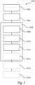
- Figure 1 discloses a flowchart of a method 1000 for manufacturing a double-walled box from a double-walled blank 100.
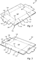
- the blank 100 is shown from a top view in Figure 2 and in a bottom view in Figure 3 .
- the blank 100 is preferably made from a paper based material such as cardboard but other materials are also envisioned.
- the blank 100 comprises a first sheet 102 for forming the inside of the box.
- the inside is the side that is intended to face the goods that is transported in the box.
- the first sheet 102 comprises a first set 104 of crease lines extending at an angle in relation to a second set 108 of crease lines of the first sheet 102.
- the first set 104 of crease lines may be arranged to extend in parallel with a first set 106 of opposed sides of the blank 100.
- the first set 104 of crease lines are arranged parallel with a short side of the blank 100.
- the first set 104 comprising two crease lines 104 extending from one long side of the blank 100 to the other opposite long side.
- Crease lines may be formed in any conventional manner that is common in the industry as is apparent to a person skilled in the art, this process will thus not be further elaborated on herein.
- the blank 100 as mentioned further comprises a second set 108 of crease lines, which may be arranged to extend in parallel with a second set 110 of opposed sides of the blank 100.
- the second set 108 of crease lines are arranged parallel with a long side of the blank 100.
- the second set 108 comprising two crease lines 108 extending from one short side of the blank 100 to the other opposite short side.
- the first and second set 104, 108 of crease lines are preferably perpendicularly arranged in relation to one another.
- the first and second set 104, 108 of crease lines forms a first pair 112 and a second pair 114 of opposing inner side wall sections 112, 114, an inner bottom wall section 116 and four inner corner sections 118.
- the blank 100 further comprising four corner crease lines 120 each extending in a respective inner corner section 118 from a respective intersection 122 between one crease line of the first set 104 of crease lines and one crease line of the second set 108 of crease lines to a corner 124 associated with the inner corner section 118.
- Each corner crease line 120 may thus extend diagonally through the respective inner corner section 118.
- Each corner 124 may comprise a rectangular cut-out, facilitating folding of the inner corner section 118, the corner crease lines 120 ending at a respective cut-out.
- the blank 100 may further comprise a second sheet 126 for forming the outside of the box 200.
- the second sheet 126 comprising a first set 128 of crease lines extending at an angle in relation to a second set 132 of crease lines.
- the first set 128 of crease lines may extend in parallel with the first set 106 of opposed sides of the blank 100 and the second set 132 of crease lines may extend in parallel with the second set 110 of opposed sides of the blank 100.
- the first and second set 128, 132 of crease lines form a first 134 and a second pair 136 of opposing outer side wall sections, an outer bottom wall section 138 and four outer corner sections 140.
- the second sheet 126 is preferably connected to the first sheet 102 along the second set 110 of opposed sides such that each of the second pair of outer side wall sections 136 is arranged with spaced apart from the respective one of the second pair of inner side wall sections 114.
- the second set 132 of crease lines of the second sheet 126 comprises terminal sections 142 formed as slits which allows the outer corner sections 140 to be folded about the first set 128 of crease lines.
- the slits may be formed tapering from the first set 106 of opposite sides towards the first set of crease lines 128, faciltating folding of the outer corner sections 140.
- the method 1000 for manufacturing a double-walled box from the double-walled blank 100 comprises transferring 1002 the blank 100 to a first position in a blank folding machine 200, such that the inner bottom wall section 116 is positioned above an opening 202 with the first sheet 102 facing away from the opening 202.
- the blank 100 comprises a second sheet 126 for forming the outside of the box 200, that the inner bottom wall section 116, in the first position, is positioned above the opening 202 with the first sheet 102 facing away from the opening 202 entails that the outer bottom wall section 138, in the first position, is positioned above the opening 202 with the second sheet 126 facing into the opening 202.
- transferring the blank 100 to a first position further comprises that the outer bottom wall section 138 is positioned above the opening 202 with the second sheet 126 facing into the opening 202.
- the blank 100 is illustrated in the first position in Figures 4a and 4b .
- the blank 100 may be transferred 1002 to the first position for instance by means of a conveyer belt. Alternatively, the blank 100 may be manually transferred 1002 to the first position.
- the method 1000 further comprises engaging 1004 from above each inner corner section 118 by a corner section securing device 206.
- the corner section securing device 206 facilitates controlling the folding of each corner section 118, such that corner crease lines 120 folds outwards towards the outer corner section 140.
- the method further comprises pushing down 1006 the inner bottom wall section 116 into the opening 202 by a plunger 204 of the apparatus 200.
- the plunger 204 applies pressure on the inner bottom wall section 116, forcing the blank 100 into the opening 202 in the apparatus 200.
- the step of the pushing down comprises a first phase 1008 during which the blank 100 is moved from the first position to a second position and in which a first engagement member 208 folds the first pair 112 of opposing inner side wall sections 112 for initiation of erection thereof while maintaining the engaging from above for controlling folding about the four corner crease lines 120.
- the engaging from above on each inner corner section 118 may be discontinued by the corner section securing device 106 during the first phase 1008.
- the blank 100 is shown in its second position in Figures 5a and 5b, 5b showing a state of the folding of the blank 100.
- the second position of the blank 100 may comprises initiation of erection of the second pair 114 of opposing inner side wall sections, as the erection of the first pair 112 of inner side wall sections may bring about folding of the second pair 114 of inner side wall sections as they are connected through the inner corner sections 118.
- the pushing down 1006 further comprises a second phase 1010 in which the blank 100 is moved from the second position into a third position illustrated in Figures 6a and 6b .
- a second engagement member 212 folds the second pair 114 of opposing inner side wall sections for erection thereof.
- the second engagement member 212 Since the second sheet 126 is connected to the first sheet 102, the second engagement member 212, while folding the second pair 114 of opposing inner side wall sections for erection thereof, simultaneously folds the outer side wall sections 136. Thus, in the second phase, the second engagement member 212 folds the second pair 136 of opposing outer side wall sections for erection thereof.
- a corner engagement member 216 folds the inner corner sections 118 such that the inner corner sections are folded about one crease line of the first set 104 of crease lines and/or one crease line of the second set 108 of crease lines.
- each inner corner section 118 is folded about one of the first set 104 of crease lines and one of the second set 108 of crease lines.
- the folding of each inner corner section 118 by the corner engagement member 216 may furhter entail folding about the associated corner crease line 120.
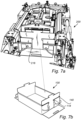
- the folding of the inner corner sections 118 forms flaps which are pressed against the inner side wall sections 112, 114 by the corner engagement member 216, as illustrated in Figures 7a and 7b .
- the blank 100 may as mentioned in foregoing comprise a second sheet 126 for forming the outside of the box 200.
- the step of pushing down 1006 may further comprises a fourth phase 1014 in which the blank 100 is moved from the third position into a fourth position in which a third engagement member 214 engages the first pair 134 of opposing outer side wall sections for erection thereof.
- the third engagment member pushing against each of the first pair 134 of opposing outer side wall sections as the blank 100 is pushed downwards by the plunger 204.
- the third engagement member 214 may further be reciprocally moveable in relation to the base structure 222 of the apparatus 200, as is elaborated further on below.
- the method 1000 may thus comprise moving the third engagment member 214 towards the first pair 134 of outer side wall sections to apply a pressure thereto during movement between the third and fourht position and further movement of the third engagment member 214 away from the first pair of outer side wall sections to release pressure once the blank 100 has reached the fourth position.
- the blank 100 is shown in the fourth positition in Figures 8a and 8b .
- the third phase 1012 may for the embodiment of the blank 100 comprising a second sheet 126 further comprise engaging the outer corner sections 140 by the corner engagement member 216 such that the outer corner sections 140 are pressed against the inner corner sections 118 for folding thereof.
- the first engagement member 208 may engage the first pair 134 of outer side wall sections during the first phase 1008 and subsequently be disengaged with the first pair 134 of outer side wall sections during the first 1008 or the second phase 1010 such that the first pair 134 of outer side wall sections are enabled to assume an unfolded state during the third phase 1012.
- This is illustrated in Figures 6a and 6b , and faciltates folding of the inner and outer corner sections 118, 140 by means of the corner enagement member 216 as is shown in Figures 7a, and 7b .
- the method 1000 may further comprise folding 1016 the top flaps 144 over the second sheet 126 by a top flap folding member 220 during or after the fourth phase 1014.
- the top flaps 144 are pushed against the respective one of the first pair of outer side wall sections 134.
- the method may further comprise a step of releasing 1018 the double-walled box, i.e. the folded blank 100, comprising moving the plunger 204 from the fourth position to the first position and engaging the double-walled box 200 by a box releasing member 218, shown in Figure 12 , pushing against the double-walled box 200 during the movement of the plunger 204 such that it releases from the plunger 204.
- the method 1000 is thus repeatable, when the plunger 204 has returned to its original position can a new blank 100 be arranged in the first position over the opening 202 in the apparatus 200.
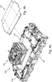
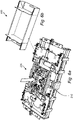
- Figure 9 discloses a perspective view of an apparatus 200 for manufacturing a double-walled box 200 from a double-walled blank 100 and thus for performing the method 1000 disclosed herein.
- the apparatus 200 comprises a base structure 222 defining an opening 202.
- the base structure 222 is configured to support the apparatus 200 and may be arranged as a part of a larger line of packaging manufacturing devices.
- the base structure 222 is preferably secured to the floor and may be provided with a stand for arranging the base structure 222 at desired height over a floor on which the apparatus 200 is placed.
- the apparatus 200 further comprises a plunger 204 moveable in relation to the base structure 222 and insertable into the opening 202 of the base 222.
- the plunger 204 may be connected to the base structure 222 and supported thereby.
- the plunger 204 may be supported by another supporting structure such as from a ceiling or from another separate stand.
- the movement of the plunger 204 may be achieved in a number of ways as is realized by one skilled in the art. It may be realized by means of a hydraulic actuator, a pneumatic actuator, an electric actuator and/or by a combination thereof.
- the apparatus 200 further comprises a corner section securing device 206 supported by the base structure 222 configured to engage each inner corner section 118 from above.
- a corner section securing device 206 may be provided for each inner corner section 118 of the blank 100.
- Each corner section securing device 206 is actuatable between a position in which it applies a pressure on the respective inner corner section 118 of the blank 100 and a disengaged position where it releases the respective inner corner section 118.
- the apparatus 200 may comprise a support member 210 which the corner section securing device 206 is configured to cooperate with.
- One support member 210 may be provided for each corner section securing device 206, which the blank 100 is pushed downwards against and which supports the inner corner section 118 as it folds.
- the apparatus further comprises a first engagement member 208 supported by the base structure 222 configured to fold the first pair 112 of opposing inner side wall sections for initiation of erection thereof in response to insertion of the plunger 204 into the opening 202 while maintaining the engaging from above by the corner section securing device 106 for controlled folding about the four corner crease lines 120.
- the first engagement member 208 preferably comprises a first 208a and a second 208b element arranged on opposite sides of the opening 202 in the base 222, each element being configured to fold a respective opposite one of the first pair 112 of inner side wall sections.
- Each of the first and second element 208a, 208b may comprise an upper horizontal surface 208c and a lower vertical surface 208e, the vertical surface 208e facing into the opening 202.
- the upper horizontal surface 208c and the lower vertical surface 208e being connected by at least one inclined surface 208d.
- the lower vertical surface 208e having a vertical extension that extends into the opening 202 of the base structure 222.
- a second engagement member 212 is further provided.
- the second engagement member 212 being supported by the base structure 222 and configured to fold the second pair 114 of said opposing inner side wall sections for erection thereof in response to continued insertion of the plunger 204 into the opening 202.
- the second engagement member 212 may, as is shown in Figure 9 , comprise a first 212a and a second 212b element arranged on opposite sides of the opening 202 in the base 222.
- the first and second elements 212a, 212b of the second engagement member 212 are preferably arranged higher above the opening 202 than the first and second elements 208a, 208b of the first engagement member 208. This facilitates that the initiation of erecting of the first pair 112 of opposite inner side wall sections is performed before the erecting of the second pair 114 of opposite inner side wall sections.
- Each of the first and second element 212a, 212b may comprise an upper horizontal surface 212c and a lower vertical surface 212e, the vertical surface 212e facing into the opening 212.
- the upper horizontal surface 212c and the lower vertical surface 212e being connected by at least one inclined surface 212d.
- the lower vertical surface 212e having a vertical extension that extends into the opening 202 of the base structure 222.
- the lower vertical surface 212e preferably extends further into the opening than the lower vertical surface 208e of the first engagement member 208.
- the apparatus 200 further comprises a corner engagement member 216 supported by the base structure 222 configured to fold the inner corner sections 118 such that each inner corner section 118 is folded about one crease line of the first set 104 of crease lines and/or one crease line of the second set 108 of crease lines for formation of flaps which are pressed against the inner side wall sections 112, 114.
- each inner corner section 118 folded about one crease line of the first 104 of crease lines and one crease line of the second set 108 of crease lines.
- the corner engagement member 216 may be configured to engage the outer corner sections 140 such that the outer corner sections 140 are pressed against the inner corner sections 118 for folding thereof.
- the apparatus may further comprise two opposite moveable portions 226, each moveable portion 226 being moveable in relation to the base structure 222 in a guided movement on at least one guiding element 224.
- the guiding element 224 guiding the movement of the moveable portions 226 such that reciprocal movement can be achieved in the direction of the first set of opposite sides 206 of the blank 200 is intended to be arranged on the apparatus 200.
- the moveable portions 226 are configured to be reciprocally moveable towards/away from the second engagement member 212.
- the moveable portions 226 define the size of the opening 202 in the base structure 222, allowing adaptation thereof.
- the moveable portions may be moveable by means of a respective actuator 228, which may be an electric, hydraulic, or pneumatic actuator as is realized by one skilled in the art.
- the actuator is connected between each moveable portion 226 and the base structure 222, allowing controlled relative movement thereof guided by the guiding element 224.
- the method 1000 disclosed herein may thus further comprise moving each moveable portion 226 to adapt the size of the opening 202 to a desired size of a blank 100 that is to be folded.
- each moveable portion may a first engagement member 208 and two corner section securing devices 206 mounted.
- Two support members 210 may further be mounted on each moveable portion 226. The position of the first engagement member 208 and the corner section securing devices 206 can thus be controlled in relation to the second engagement member 212.
- the method 1000 disclosed herein may thus further comprise controlling the position of each moveable portion 226 during the movement of the plunger 204, facilitating control of the folding of the blank 100.
- the size of the opening 200 can be adapted to suit a plurality of dimensions of the blank 100 by moving the moveable portions 226 correspondingly.
- the apparatus 200 further comprises a third engagement member 214 configured to engage the first pair 134 of opposing outer side wall sections for erection of the first pair 112, 134 of the respective outer and inner side wall sections in response to continued insertion of the plunger 204 into the opening 202.
- a third engagement member 214 configured to engage the first pair 134 of opposing outer side wall sections for erection of the first pair 112, 134 of the respective outer and inner side wall sections in response to continued insertion of the plunger 204 into the opening 202.
- a third engagement member 214 provided in the opening 202 on each side thereof configured to face towards the first pair 134 of opposing outer side wall sections.
- a third engagement member 214 may be mounted on each moveable portion 226 of the apparatus 200.
- each corner section securing device 206 may comprise an actuator 206b configured to pivot the corner section securing device 206 around a pivot axis 206a.
- the actuator 206b may be electric, hydraulic or a pneumatic actuator.
- Each corner section securing device 206 further comprising a fixation element 206c, configured to engage the inner corner section 118.
- the fixation element 206c has an extension essentially in the direction of the associated corner crease 120.
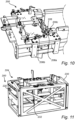
- Figure 11 discloses a perspective detail view of the plunger 204.
- the plunger 204 may comprise opposite side portions 230 which are intended to face a respective one of the first pair 112 of opposing inner side wall sections.
- the side sections 230 may be reciprocally moveable in relation to the plunger 204 such that the size of the plunger 204 can be adapted to the size of various blanks 100.
- the size of bottom part of the plunger 204 should essentially correspond to the inner bottom wall section 116 of the blank 100.
- the plunger 204 comprises a top flap folding member 220, preferably one on each side section 230.
- Each top flap folding member is configured to fold the top flaps 144 of the blank 100 over the second sheet 126 during or after the fourth phase 1014 of the method disclosed herein.
- Each top flap folding member 220 is for the purpose configured to pivot in relation plunger 204.
- Each top flap folding member 220 is provided with a shape that folds the top flap 144 in an essentially perpendicular manner over the second sheet 126, more specifically the first pair 134 of opposite side wall sections thereof.
- Each top flap folding member 220 is thus preferably provided with a bend, essentially perpendicularly, around an axis parallel with the axis around which the top flap folding member 220 pivots.
- Each top flap folding member 204 may be configured to controlled by an actuator 232, which may be electrically, pneumatically, or hydraulically operated.
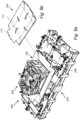
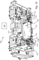
- FIG 12 shows the apparatus 200 in a bottom perspective view.
- each third engagement member 214 may be provided with a supporting element 214a at opposite sides of which two rollers 214b are arranged.
- the rollers 214b are configured to be rolled against lateral sides of the first pair of opposing outer side wall sections 134 as the plunger 204 pushes the blank 100 downwards through the opening 202.
- the third engagement member 214 may further be configured to be reciprocally moveable in relation to the base structure 222 towards and away from the first pair 134 of opposing outer side wall sections, preferably controlled by means of an actuator 214c.
- the actuator 214c may be an electric, hydraulic, or pneumatic actuator.
- corner engagement member 216 may comprise a pivoting element 216 for each inner corner section 118.
- Each pivoting element 216 being configured to pivot in relation to the base 222 to fold the inner corner sections 118 such that the inner corner sections 118 are folded about the associated corner crease line 120 for formation of flaps which are pressed against the inner side wall sections 112.
- Each pivoting element 216 may be connected to a respective actuator 216a for controlling the pivoting movement thereof.
- the actuator 216a may be an electric, hydraulic, or pneumatic actuator.
- the pivoting elements 216 may be configured to fold the inner corner sections 118 by pushing against the outer corner sections 140, thus folding both the inner corner sections 118 and the outer corner sections 140 of the blank 100 simultaneously, as illustrated in Figure 7a and 7b .
- the apparatus 200 may comprise a box releasing member 218 configured to engage the double-walled box 300 by pushing against the double-walled box 300 during upwards movement of the plunger 204 such that it releases the box 300 from the plunger 204.
- a box releasing member 218 configured to engage the double-walled box 300 by pushing against the double-walled box 300 during upwards movement of the plunger 204 such that it releases the box 300 from the plunger 204.
- Each box releasing member 218 is moveable from a retracted position to an extended position, in the retracted position it lets the blank 100 or box 300 pass freely while it in the extended position extends into the opening such that it engages with the box 300.
- the movement of each box releasing member 218 may be spring actuated or achieved by means of an electric, hydraulic, or pneumatic actuator.
- control unit 400 may be provided.
- the control unit 400 may be formed by a single unit being configured to carry out overall control of functions and operations of the apparatus 200, more particularly the method 1000 disclosed herein.
- the control unit 400 may thus comprise a control circuit which may be associated with a memory.
- the control circuit may include an associated processor, such as a central processing unit (CPU), microcontroller, or microprocessor.
- the processor is configured to execute program code stored in the memory, in order to carry out functions and operations of the control unit 400.
- the memory may be one or more of a buffer, a flash memory, a hard drive, a removable media, a volatile memory, a non-volatile memory, a random access memory (RAM), or another suitable device.
- the memory may include a non-volatile memory for long term data storage and a volatile memory that functions as system memory for the control circuit.
- the memory may exchange data with the control circuit over a data bus. Accompanying control lines and an address bus between the memory and the control circuit also may be present.
- the control unit 400 may further comprise a communication unit, connected to the control circuit to facilitate remote control of functions of the associated apparatus 200.
- the communication path over which the communication is made may be wired or wireless.
- the communication may include data transfers, and the like. Data transfers may include, but are not limited to, downloading and/or uploading data and receiving or sending messages.
- the data may be processed by the control unit 400.
- the processing may include storing the data in a memory, e.g. the memory of the control unit 400, executing operations or functions, and so forth.
- Functions and operations of the control unit 400 may be embodied in the form of executable logic routines (e.g., lines of code, software programs, etc.) that are stored on a non-transitory computer readable medium (e.g., the memory) of the control unit 400 and are executed by the control circuit (e.g., using the processor).
- the functions and operations of the control unit 400 may be a stand-alone software application or form a part of a software application that carries out additional tasks related to the control unit 400.
- the described functions and operations may be considered a method that the corresponding apparatus 200 is configured to carry out.
Landscapes
- Engineering & Computer Science (AREA)
- Mechanical Engineering (AREA)
- Making Paper Articles (AREA)
Applications Claiming Priority (1)
| Application Number | Priority Date | Filing Date | Title |
|---|---|---|---|
| SE2151120 | 2021-09-10 |
Publications (4)
| Publication Number | Publication Date |
|---|---|
| EP4147986A2 true EP4147986A2 (de) | 2023-03-15 |
| EP4147986A3 EP4147986A3 (de) | 2023-06-07 |
| EP4147986C0 EP4147986C0 (de) | 2025-01-15 |
| EP4147986B1 EP4147986B1 (de) | 2025-01-15 |
Family
ID=83271064
Family Applications (1)
| Application Number | Title | Priority Date | Filing Date |
|---|---|---|---|
| EP22194840.9A Active EP4147986B1 (de) | 2021-09-10 | 2022-09-09 | Verfahren und vorrichtung zur herstellung einer doppelwandigen schachtel aus einem doppelwandigen zuschnitt |
Country Status (2)
| Country | Link |
|---|---|
| EP (1) | EP4147986B1 (de) |
| ES (1) | ES3020341T3 (de) |
Cited By (1)
| Publication number | Priority date | Publication date | Assignee | Title |
|---|---|---|---|---|
| IT202300019533A1 (it) * | 2023-09-22 | 2025-03-22 | All Glass S R L | Apparecchiatura per la realizzazione di vassoi bordati di dimensioni o tipologie diverse |
Family Cites Families (6)
| Publication number | Priority date | Publication date | Assignee | Title |
|---|---|---|---|---|
| DE362194C (de) * | 1920-06-03 | 1922-10-25 | Harry Bridgman Smith | Maschine zum Herstellen von lose oder fest mit Papier bekleideten Pappschachteln |
| US2714344A (en) * | 1953-08-03 | 1955-08-02 | Baljak Corp | Machine for the automatic assembly of folding boxes of the hollow-walled type |
| DE1015670B (de) * | 1955-02-11 | 1957-09-12 | Baljak Corp | Vorrichtung zum Zusammenfuegen von Schachtelecken |
| US2997930A (en) * | 1959-09-01 | 1961-08-29 | Baljak Corp | Device for forming and locking folding box corners |
| AU2014233552B2 (en) * | 2013-09-23 | 2019-11-21 | Opal Packaging Australia Pty Ltd | Machine for erecting a carton from a blank |
| IT201800003079A1 (it) * | 2018-02-27 | 2019-08-27 | Europrogetti Srl | Apparecchiatura e procedimento per la rivestitura di scatole in cartone prive di cucitura |
-
2022
- 2022-09-09 EP EP22194840.9A patent/EP4147986B1/de active Active
- 2022-09-09 ES ES22194840T patent/ES3020341T3/es active Active
Cited By (2)
| Publication number | Priority date | Publication date | Assignee | Title |
|---|---|---|---|---|
| IT202300019533A1 (it) * | 2023-09-22 | 2025-03-22 | All Glass S R L | Apparecchiatura per la realizzazione di vassoi bordati di dimensioni o tipologie diverse |
| EP4527607A1 (de) * | 2023-09-22 | 2025-03-26 | All Glass S.r.l. | Vorrichtung für die herstellung von abgekanteten schalen mit unterschiedlichem abmessungen oder typen |
Also Published As
| Publication number | Publication date |
|---|---|
| EP4147986A3 (de) | 2023-06-07 |
| ES3020341T3 (en) | 2025-05-22 |
| EP4147986C0 (de) | 2025-01-15 |
| EP4147986B1 (de) | 2025-01-15 |
Similar Documents
| Publication | Publication Date | Title |
|---|---|---|
| US11618234B2 (en) | Methods and a machine for forming a container from a blank | |
| US11559962B2 (en) | Methods and machine for forming a two-piece blank assembly | |
| US11718058B2 (en) | Folding unit for folding cardboard blanks, folding apparatus comprising such folding unit and method for folding cardboard blanks | |
| JP2022125114A (ja) | ボックス組立ての方法およびシステム | |
| US10759133B2 (en) | Machine for automatically manufacturing customized packaging items | |
| US9145222B2 (en) | Folding method and apparatus for making a carton | |
| US20100204030A1 (en) | Collapsed Tubular Carton Erecting Apparatus & Methods | |
| US11981102B2 (en) | Machine for forming a container from a blank | |
| EP4147986B1 (de) | Verfahren und vorrichtung zur herstellung einer doppelwandigen schachtel aus einem doppelwandigen zuschnitt | |
| CN117104616B (zh) | 一种开箱套箱机及其使用方法 | |
| CN113619871B (zh) | 一种装盒机 | |
| ITRE20100016A1 (it) | Apparecchiatura e metodo per la formazione di vassoi bordati | |
| JP2009012859A (ja) | カートンマガジン、カートンハンド及び文書積載挿入装置 | |
| JP2021037637A (ja) | 箱詰め装置 | |
| US20190232596A1 (en) | Method and device for shaping a blank around a mandrel | |
| US20080168749A1 (en) | Apparatus and method for packaging siding panels | |
| JP7142911B2 (ja) | 箱のフラップ拡開装置 | |
| JP2022027616A (ja) | ボックス起立装置及びその方法 | |
| EP4401969B1 (de) | Vorrichtung und verfahren zum umhüllen einer kartonschachtel | |
| US12559277B1 (en) | Method and apparatus for opening knock down flat boxes | |
| US12611835B2 (en) | Apparatus and method for wrapping a cardboard box | |
| NL2036340B1 (en) | Case Erector Apparatus and Method for Erecting Left-Handed or Right-Handed Cases | |
| JP2019142579A (ja) | 製函用型、製函装置および製函方法 | |
| CN119503236A (zh) | 一种单机械臂组箱套箱装置及其使用方法 | |
| CN120383054A (zh) | 纸箱包装折盒机 |
Legal Events
| Date | Code | Title | Description |
|---|---|---|---|
| PUAI | Public reference made under article 153(3) epc to a published international application that has entered the european phase |
Free format text: ORIGINAL CODE: 0009012 |
|
| STAA | Information on the status of an ep patent application or granted ep patent |
Free format text: STATUS: THE APPLICATION HAS BEEN PUBLISHED |
|
| AK | Designated contracting states |
Kind code of ref document: A2 Designated state(s): AL AT BE BG CH CY CZ DE DK EE ES FI FR GB GR HR HU IE IS IT LI LT LU LV MC MK MT NL NO PL PT RO RS SE SI SK SM TR |
|
| REG | Reference to a national code |
Ref country code: DE Free format text: PREVIOUS MAIN CLASS: B65D0005200000 Ref country code: DE Ref legal event code: R079 Ref document number: 602022009527 Country of ref document: DE Free format text: PREVIOUS MAIN CLASS: B65D0005200000 Ipc: B31B0050440000 |
|
| PUAL | Search report despatched |
Free format text: ORIGINAL CODE: 0009013 |
|
| AK | Designated contracting states |
Kind code of ref document: A3 Designated state(s): AL AT BE BG CH CY CZ DE DK EE ES FI FR GB GR HR HU IE IS IT LI LT LU LV MC MK MT NL NO PL PT RO RS SE SI SK SM TR |
|
| RIC1 | Information provided on ipc code assigned before grant |
Ipc: B31B 120/40 20170101ALN20230502BHEP Ipc: B31B 110/35 20170101ALN20230502BHEP Ipc: B31B 100/00 20170101ALN20230502BHEP Ipc: B65D 81/38 20060101ALI20230502BHEP Ipc: B65D 5/56 20060101ALI20230502BHEP Ipc: B65D 5/30 20060101ALI20230502BHEP Ipc: B65D 5/24 20060101ALI20230502BHEP Ipc: B65D 5/22 20060101ALI20230502BHEP Ipc: B65D 5/20 20060101ALI20230502BHEP Ipc: B31B 50/50 20170101ALI20230502BHEP Ipc: B31B 50/26 20170101ALI20230502BHEP Ipc: B31B 50/44 20170101AFI20230502BHEP |
|
| STAA | Information on the status of an ep patent application or granted ep patent |
Free format text: STATUS: REQUEST FOR EXAMINATION WAS MADE |
|
| 17P | Request for examination filed |
Effective date: 20231206 |
|
| RBV | Designated contracting states (corrected) |
Designated state(s): AL AT BE BG CH CY CZ DE DK EE ES FI FR GB GR HR HU IE IS IT LI LT LU LV MC MK MT NL NO PL PT RO RS SE SI SK SM TR |
|
| GRAP | Despatch of communication of intention to grant a patent |
Free format text: ORIGINAL CODE: EPIDOSNIGR1 |
|
| STAA | Information on the status of an ep patent application or granted ep patent |
Free format text: STATUS: GRANT OF PATENT IS INTENDED |
|
| RIC1 | Information provided on ipc code assigned before grant |
Ipc: B31B 120/40 20170101ALN20240723BHEP Ipc: B31B 110/35 20170101ALN20240723BHEP Ipc: B31B 100/00 20170101ALN20240723BHEP Ipc: B65D 81/38 20060101ALI20240723BHEP Ipc: B65D 5/56 20060101ALI20240723BHEP Ipc: B65D 5/30 20060101ALI20240723BHEP Ipc: B65D 5/24 20060101ALI20240723BHEP Ipc: B65D 5/22 20060101ALI20240723BHEP Ipc: B65D 5/20 20060101ALI20240723BHEP Ipc: B31B 50/50 20170101ALI20240723BHEP Ipc: B31B 50/26 20170101ALI20240723BHEP Ipc: B31B 50/44 20170101AFI20240723BHEP |
|
| INTG | Intention to grant announced |
Effective date: 20240807 |
|
| GRAS | Grant fee paid |
Free format text: ORIGINAL CODE: EPIDOSNIGR3 |
|
| GRAA | (expected) grant |
Free format text: ORIGINAL CODE: 0009210 |
|
| STAA | Information on the status of an ep patent application or granted ep patent |
Free format text: STATUS: THE PATENT HAS BEEN GRANTED |
|
| AK | Designated contracting states |
Kind code of ref document: B1 Designated state(s): AL AT BE BG CH CY CZ DE DK EE ES FI FR GB GR HR HU IE IS IT LI LT LU LV MC MK MT NL NO PL PT RO RS SE SI SK SM TR |
|
| REG | Reference to a national code |
Ref country code: CH Ref legal event code: EP Ref country code: GB Ref legal event code: FG4D |
|
| REG | Reference to a national code |
Ref country code: DE Ref legal event code: R096 Ref document number: 602022009527 Country of ref document: DE |
|
| REG | Reference to a national code |
Ref country code: IE Ref legal event code: FG4D |
|
| U01 | Request for unitary effect filed |
Effective date: 20250115 |
|
| U07 | Unitary effect registered |
Designated state(s): AT BE BG DE DK EE FI FR IT LT LU LV MT NL PT RO SE SI Effective date: 20250129 |
|
| REG | Reference to a national code |
Ref country code: ES Ref legal event code: FG2A Ref document number: 3020341 Country of ref document: ES Kind code of ref document: T3 Effective date: 20250522 |
|
| PG25 | Lapsed in a contracting state [announced via postgrant information from national office to epo] |
Ref country code: RS Free format text: LAPSE BECAUSE OF FAILURE TO SUBMIT A TRANSLATION OF THE DESCRIPTION OR TO PAY THE FEE WITHIN THE PRESCRIBED TIME-LIMIT Effective date: 20250415 |
|
| PG25 | Lapsed in a contracting state [announced via postgrant information from national office to epo] |
Ref country code: PL Free format text: LAPSE BECAUSE OF FAILURE TO SUBMIT A TRANSLATION OF THE DESCRIPTION OR TO PAY THE FEE WITHIN THE PRESCRIBED TIME-LIMIT Effective date: 20250115 |
|
| PG25 | Lapsed in a contracting state [announced via postgrant information from national office to epo] |
Ref country code: HR Free format text: LAPSE BECAUSE OF FAILURE TO SUBMIT A TRANSLATION OF THE DESCRIPTION OR TO PAY THE FEE WITHIN THE PRESCRIBED TIME-LIMIT Effective date: 20250115 |
|
| PG25 | Lapsed in a contracting state [announced via postgrant information from national office to epo] |
Ref country code: GR Free format text: LAPSE BECAUSE OF FAILURE TO SUBMIT A TRANSLATION OF THE DESCRIPTION OR TO PAY THE FEE WITHIN THE PRESCRIBED TIME-LIMIT Effective date: 20250416 |
|
| PG25 | Lapsed in a contracting state [announced via postgrant information from national office to epo] |
Ref country code: SM Free format text: LAPSE BECAUSE OF FAILURE TO SUBMIT A TRANSLATION OF THE DESCRIPTION OR TO PAY THE FEE WITHIN THE PRESCRIBED TIME-LIMIT Effective date: 20250115 |
|
| PGFP | Annual fee paid to national office [announced via postgrant information from national office to epo] |
Ref country code: NO Payment date: 20250917 Year of fee payment: 4 |
|
| PG25 | Lapsed in a contracting state [announced via postgrant information from national office to epo] |
Ref country code: CZ Free format text: LAPSE BECAUSE OF FAILURE TO SUBMIT A TRANSLATION OF THE DESCRIPTION OR TO PAY THE FEE WITHIN THE PRESCRIBED TIME-LIMIT Effective date: 20250115 |
|
| U20 | Renewal fee for the european patent with unitary effect paid |
Year of fee payment: 4 Effective date: 20250916 |
|
| PG25 | Lapsed in a contracting state [announced via postgrant information from national office to epo] |
Ref country code: SK Free format text: LAPSE BECAUSE OF FAILURE TO SUBMIT A TRANSLATION OF THE DESCRIPTION OR TO PAY THE FEE WITHIN THE PRESCRIBED TIME-LIMIT Effective date: 20250115 |
|
| PGFP | Annual fee paid to national office [announced via postgrant information from national office to epo] |
Ref country code: IS Payment date: 20250910 Year of fee payment: 4 |
|
| PLBE | No opposition filed within time limit |
Free format text: ORIGINAL CODE: 0009261 |
|
| STAA | Information on the status of an ep patent application or granted ep patent |
Free format text: STATUS: NO OPPOSITION FILED WITHIN TIME LIMIT |
|
| REG | Reference to a national code |
Ref country code: CH Ref legal event code: L10 Free format text: ST27 STATUS EVENT CODE: U-0-0-L10-L00 (AS PROVIDED BY THE NATIONAL OFFICE) Effective date: 20251126 |
|
| 26N | No opposition filed |
Effective date: 20251016 |
|
| PGFP | Annual fee paid to national office [announced via postgrant information from national office to epo] |
Ref country code: ES Payment date: 20251001 Year of fee payment: 4 |
|
| REG | Reference to a national code |
Ref country code: CH Ref legal event code: H13 Free format text: ST27 STATUS EVENT CODE: U-0-0-H10-H13 (AS PROVIDED BY THE NATIONAL OFFICE) Effective date: 20260504 |
|
| PG25 | Lapsed in a contracting state [announced via postgrant information from national office to epo] |
Ref country code: MC Free format text: LAPSE BECAUSE OF FAILURE TO SUBMIT A TRANSLATION OF THE DESCRIPTION OR TO PAY THE FEE WITHIN THE PRESCRIBED TIME-LIMIT Effective date: 20250115 |
|
| PG25 | Lapsed in a contracting state [announced via postgrant information from national office to epo] |
Ref country code: CH Free format text: LAPSE BECAUSE OF NON-PAYMENT OF DUE FEES Effective date: 20250930 Ref country code: IE Free format text: LAPSE BECAUSE OF NON-PAYMENT OF DUE FEES Effective date: 20250909 |