EP4147902A1 - Liquid-cooled charging connector - Google Patents
Liquid-cooled charging connector Download PDFInfo
- Publication number
- EP4147902A1 EP4147902A1 EP22203497.7A EP22203497A EP4147902A1 EP 4147902 A1 EP4147902 A1 EP 4147902A1 EP 22203497 A EP22203497 A EP 22203497A EP 4147902 A1 EP4147902 A1 EP 4147902A1
- Authority
- EP
- European Patent Office
- Prior art keywords
- charging
- charging connector
- coupled
- connector
- sleeve
- Prior art date
- Legal status (The legal status is an assumption and is not a legal conclusion. Google has not performed a legal analysis and makes no representation as to the accuracy of the status listed.)
- Pending
Links
- 239000012809 cooling fluid Substances 0.000 claims abstract description 27
- 238000001816 cooling Methods 0.000 claims abstract description 7
- 238000011144 upstream manufacturing Methods 0.000 claims abstract description 6
- 239000000463 material Substances 0.000 claims description 8
- 238000000034 method Methods 0.000 claims description 7
- 230000008569 process Effects 0.000 claims description 6
- 238000010276 construction Methods 0.000 claims description 3
- RVCKCEDKBVEEHL-UHFFFAOYSA-N 2,3,4,5,6-pentachlorobenzyl alcohol Chemical compound OCC1=C(Cl)C(Cl)=C(Cl)C(Cl)=C1Cl RVCKCEDKBVEEHL-UHFFFAOYSA-N 0.000 claims 3
- 239000012530 fluid Substances 0.000 description 27
- 238000004146 energy storage Methods 0.000 description 7
- 230000004048 modification Effects 0.000 description 4
- 238000012986 modification Methods 0.000 description 4
- LYCAIKOWRPUZTN-UHFFFAOYSA-N Ethylene glycol Chemical compound OCCO LYCAIKOWRPUZTN-UHFFFAOYSA-N 0.000 description 3
- 230000008901 benefit Effects 0.000 description 2
- 239000004020 conductor Substances 0.000 description 2
- 230000008878 coupling Effects 0.000 description 2
- 238000010168 coupling process Methods 0.000 description 2
- 238000005859 coupling reaction Methods 0.000 description 2
- 238000006243 chemical reaction Methods 0.000 description 1
- 230000001419 dependent effect Effects 0.000 description 1
- 239000012777 electrically insulating material Substances 0.000 description 1
- 230000014509 gene expression Effects 0.000 description 1
- 230000004044 response Effects 0.000 description 1
- 239000000758 substrate Substances 0.000 description 1
Images


Classifications
-
- B—PERFORMING OPERATIONS; TRANSPORTING
- B60—VEHICLES IN GENERAL
- B60L—PROPULSION OF ELECTRICALLY-PROPELLED VEHICLES; SUPPLYING ELECTRIC POWER FOR AUXILIARY EQUIPMENT OF ELECTRICALLY-PROPELLED VEHICLES; ELECTRODYNAMIC BRAKE SYSTEMS FOR VEHICLES IN GENERAL; MAGNETIC SUSPENSION OR LEVITATION FOR VEHICLES; MONITORING OPERATING VARIABLES OF ELECTRICALLY-PROPELLED VEHICLES; ELECTRIC SAFETY DEVICES FOR ELECTRICALLY-PROPELLED VEHICLES
- B60L53/00—Methods of charging batteries, specially adapted for electric vehicles; Charging stations or on-board charging equipment therefor; Exchange of energy storage elements in electric vehicles
- B60L53/10—Methods of charging batteries, specially adapted for electric vehicles; Charging stations or on-board charging equipment therefor; Exchange of energy storage elements in electric vehicles characterised by the energy transfer between the charging station and the vehicle
- B60L53/14—Conductive energy transfer
- B60L53/16—Connectors, e.g. plugs or sockets, specially adapted for charging electric vehicles
-
- B—PERFORMING OPERATIONS; TRANSPORTING
- B60—VEHICLES IN GENERAL
- B60L—PROPULSION OF ELECTRICALLY-PROPELLED VEHICLES; SUPPLYING ELECTRIC POWER FOR AUXILIARY EQUIPMENT OF ELECTRICALLY-PROPELLED VEHICLES; ELECTRODYNAMIC BRAKE SYSTEMS FOR VEHICLES IN GENERAL; MAGNETIC SUSPENSION OR LEVITATION FOR VEHICLES; MONITORING OPERATING VARIABLES OF ELECTRICALLY-PROPELLED VEHICLES; ELECTRIC SAFETY DEVICES FOR ELECTRICALLY-PROPELLED VEHICLES
- B60L53/00—Methods of charging batteries, specially adapted for electric vehicles; Charging stations or on-board charging equipment therefor; Exchange of energy storage elements in electric vehicles
- B60L53/10—Methods of charging batteries, specially adapted for electric vehicles; Charging stations or on-board charging equipment therefor; Exchange of energy storage elements in electric vehicles characterised by the energy transfer between the charging station and the vehicle
- B60L53/14—Conductive energy transfer
- B60L53/18—Cables specially adapted for charging electric vehicles
-
- B—PERFORMING OPERATIONS; TRANSPORTING
- B60—VEHICLES IN GENERAL
- B60L—PROPULSION OF ELECTRICALLY-PROPELLED VEHICLES; SUPPLYING ELECTRIC POWER FOR AUXILIARY EQUIPMENT OF ELECTRICALLY-PROPELLED VEHICLES; ELECTRODYNAMIC BRAKE SYSTEMS FOR VEHICLES IN GENERAL; MAGNETIC SUSPENSION OR LEVITATION FOR VEHICLES; MONITORING OPERATING VARIABLES OF ELECTRICALLY-PROPELLED VEHICLES; ELECTRIC SAFETY DEVICES FOR ELECTRICALLY-PROPELLED VEHICLES
- B60L53/00—Methods of charging batteries, specially adapted for electric vehicles; Charging stations or on-board charging equipment therefor; Exchange of energy storage elements in electric vehicles
- B60L53/30—Constructional details of charging stations
- B60L53/302—Cooling of charging equipment
-
- H—ELECTRICITY
- H01—ELECTRIC ELEMENTS
- H01R—ELECTRICALLY-CONDUCTIVE CONNECTIONS; STRUCTURAL ASSOCIATIONS OF A PLURALITY OF MUTUALLY-INSULATED ELECTRICAL CONNECTING ELEMENTS; COUPLING DEVICES; CURRENT COLLECTORS
- H01R13/00—Details of coupling devices of the kinds covered by groups H01R12/70 or H01R24/00 - H01R33/00
- H01R13/005—Electrical coupling combined with fluidic coupling
-
- H—ELECTRICITY
- H01—ELECTRIC ELEMENTS
- H01R—ELECTRICALLY-CONDUCTIVE CONNECTIONS; STRUCTURAL ASSOCIATIONS OF A PLURALITY OF MUTUALLY-INSULATED ELECTRICAL CONNECTING ELEMENTS; COUPLING DEVICES; CURRENT COLLECTORS
- H01R13/00—Details of coupling devices of the kinds covered by groups H01R12/70 or H01R24/00 - H01R33/00
- H01R13/40—Securing contact members in or to a base or case; Insulating of contact members
- H01R13/405—Securing in non-demountable manner, e.g. moulding, riveting
-
- H—ELECTRICITY
- H01—ELECTRIC ELEMENTS
- H01R—ELECTRICALLY-CONDUCTIVE CONNECTIONS; STRUCTURAL ASSOCIATIONS OF A PLURALITY OF MUTUALLY-INSULATED ELECTRICAL CONNECTING ELEMENTS; COUPLING DEVICES; CURRENT COLLECTORS
- H01R13/00—Details of coupling devices of the kinds covered by groups H01R12/70 or H01R24/00 - H01R33/00
- H01R13/46—Bases; Cases
- H01R13/52—Dustproof, splashproof, drip-proof, waterproof, or flameproof cases
- H01R13/5202—Sealing means between parts of housing or between housing part and a wall, e.g. sealing rings
-
- H—ELECTRICITY
- H01—ELECTRIC ELEMENTS
- H01R—ELECTRICALLY-CONDUCTIVE CONNECTIONS; STRUCTURAL ASSOCIATIONS OF A PLURALITY OF MUTUALLY-INSULATED ELECTRICAL CONNECTING ELEMENTS; COUPLING DEVICES; CURRENT COLLECTORS
- H01R13/00—Details of coupling devices of the kinds covered by groups H01R12/70 or H01R24/00 - H01R33/00
- H01R13/66—Structural association with built-in electrical component
- H01R13/665—Structural association with built-in electrical component with built-in electronic circuit
-
- H—ELECTRICITY
- H02—GENERATION; CONVERSION OR DISTRIBUTION OF ELECTRIC POWER
- H02J—CIRCUIT ARRANGEMENTS OR SYSTEMS FOR SUPPLYING OR DISTRIBUTING ELECTRIC POWER; SYSTEMS FOR STORING ELECTRIC ENERGY
- H02J7/00—Circuit arrangements for charging or depolarising batteries or for supplying loads from batteries
- H02J7/0042—Circuit arrangements for charging or depolarising batteries or for supplying loads from batteries characterised by the mechanical construction
-
- B—PERFORMING OPERATIONS; TRANSPORTING
- B60—VEHICLES IN GENERAL
- B60Y—INDEXING SCHEME RELATING TO ASPECTS CROSS-CUTTING VEHICLE TECHNOLOGY
- B60Y2200/00—Type of vehicle
- B60Y2200/90—Vehicles comprising electric prime movers
- B60Y2200/91—Electric vehicles
-
- B—PERFORMING OPERATIONS; TRANSPORTING
- B60—VEHICLES IN GENERAL
- B60Y—INDEXING SCHEME RELATING TO ASPECTS CROSS-CUTTING VEHICLE TECHNOLOGY
- B60Y2306/00—Other features of vehicle sub-units
- B60Y2306/05—Cooling
-
- B—PERFORMING OPERATIONS; TRANSPORTING
- B60—VEHICLES IN GENERAL
- B60Y—INDEXING SCHEME RELATING TO ASPECTS CROSS-CUTTING VEHICLE TECHNOLOGY
- B60Y2400/00—Special features of vehicle units
- B60Y2400/30—Sensors
- B60Y2400/302—Temperature sensors
-
- H—ELECTRICITY
- H01—ELECTRIC ELEMENTS
- H01R—ELECTRICALLY-CONDUCTIVE CONNECTIONS; STRUCTURAL ASSOCIATIONS OF A PLURALITY OF MUTUALLY-INSULATED ELECTRICAL CONNECTING ELEMENTS; COUPLING DEVICES; CURRENT COLLECTORS
- H01R2201/00—Connectors or connections adapted for particular applications
- H01R2201/26—Connectors or connections adapted for particular applications for vehicles
-
- Y—GENERAL TAGGING OF NEW TECHNOLOGICAL DEVELOPMENTS; GENERAL TAGGING OF CROSS-SECTIONAL TECHNOLOGIES SPANNING OVER SEVERAL SECTIONS OF THE IPC; TECHNICAL SUBJECTS COVERED BY FORMER USPC CROSS-REFERENCE ART COLLECTIONS [XRACs] AND DIGESTS
- Y02—TECHNOLOGIES OR APPLICATIONS FOR MITIGATION OR ADAPTATION AGAINST CLIMATE CHANGE
- Y02T—CLIMATE CHANGE MITIGATION TECHNOLOGIES RELATED TO TRANSPORTATION
- Y02T10/00—Road transport of goods or passengers
- Y02T10/60—Other road transportation technologies with climate change mitigation effect
- Y02T10/70—Energy storage systems for electromobility, e.g. batteries
-
- Y—GENERAL TAGGING OF NEW TECHNOLOGICAL DEVELOPMENTS; GENERAL TAGGING OF CROSS-SECTIONAL TECHNOLOGIES SPANNING OVER SEVERAL SECTIONS OF THE IPC; TECHNICAL SUBJECTS COVERED BY FORMER USPC CROSS-REFERENCE ART COLLECTIONS [XRACs] AND DIGESTS
- Y02—TECHNOLOGIES OR APPLICATIONS FOR MITIGATION OR ADAPTATION AGAINST CLIMATE CHANGE
- Y02T—CLIMATE CHANGE MITIGATION TECHNOLOGIES RELATED TO TRANSPORTATION
- Y02T10/00—Road transport of goods or passengers
- Y02T10/60—Other road transportation technologies with climate change mitigation effect
- Y02T10/7072—Electromobility specific charging systems or methods for batteries, ultracapacitors, supercapacitors or double-layer capacitors
-
- Y—GENERAL TAGGING OF NEW TECHNOLOGICAL DEVELOPMENTS; GENERAL TAGGING OF CROSS-SECTIONAL TECHNOLOGIES SPANNING OVER SEVERAL SECTIONS OF THE IPC; TECHNICAL SUBJECTS COVERED BY FORMER USPC CROSS-REFERENCE ART COLLECTIONS [XRACs] AND DIGESTS
- Y02—TECHNOLOGIES OR APPLICATIONS FOR MITIGATION OR ADAPTATION AGAINST CLIMATE CHANGE
- Y02T—CLIMATE CHANGE MITIGATION TECHNOLOGIES RELATED TO TRANSPORTATION
- Y02T90/00—Enabling technologies or technologies with a potential or indirect contribution to GHG emissions mitigation
- Y02T90/10—Technologies relating to charging of electric vehicles
- Y02T90/12—Electric charging stations
-
- Y—GENERAL TAGGING OF NEW TECHNOLOGICAL DEVELOPMENTS; GENERAL TAGGING OF CROSS-SECTIONAL TECHNOLOGIES SPANNING OVER SEVERAL SECTIONS OF THE IPC; TECHNICAL SUBJECTS COVERED BY FORMER USPC CROSS-REFERENCE ART COLLECTIONS [XRACs] AND DIGESTS
- Y02—TECHNOLOGIES OR APPLICATIONS FOR MITIGATION OR ADAPTATION AGAINST CLIMATE CHANGE
- Y02T—CLIMATE CHANGE MITIGATION TECHNOLOGIES RELATED TO TRANSPORTATION
- Y02T90/00—Enabling technologies or technologies with a potential or indirect contribution to GHG emissions mitigation
- Y02T90/10—Technologies relating to charging of electric vehicles
- Y02T90/14—Plug-in electric vehicles
Definitions
- the present disclosure generally relates to a charging connector for an electric vehicle, and more particularly to a liquid-cooled charging connector for an electric vehicle.
- Electric vehicles and hybrids generally use electric power from a rechargeable battery as a power source. These rechargeable batteries must be recharged from another energy source. Recharging can occur at a charging stating by connecting an energy supply to a vehicle's charging inlet through a cable with attached charging connector. To transfer energy faster and decrease charging times, the cable and charging connector must be capable of withstanding high current loads. Current charging connectors are limited in the current loads that they can support as their ability to dissipate heat is limited. Thus, there is a need for a new charging connector to solve the aforementioned problems.
- the present disclosure related to a new charging connector as defined in claim 1, to a charging system as defined in claim 9, and to a handle assembly for a charging connector as defined in claim 13. Embodiments are defined in the dependent claims.
- the charging connector has a manifold assembly enclosing first and second sockets coupled to respective sleeves, wherein the manifold assembly creates a hollow interior space; and an inlet conduit and an outlet conduit through which a cooling fluid flows for cooling the charging connector, wherein the cooling fluid flows in through the inlet conduit and bifurcates into two streams which flow around the sleeves and which subsequently combine together upstream to flow out of the outlet conduit.
- the cooling fluid can be recirculated back to the inlet conduit.
- a first sleeve may partially enclose the first electrical socket and a second sleeve partially encloses the second electrical socket.
- the sleeves may comprise a thermally conducting plastic material.
- the sleeves may be coupled to corresponding electrical sockets by one or more of an overmolding process, or a press-fit assembly.
- the charging connector may be configured for connection to a two part Printed Circuit Board Assembly.
- the charging connector further may comprise a pair of O rings provided between a first sleeve and the manifold assembly.
- the charging connector also may comprise a temperature sensor coupled to at least one of the electrical sockets.
- the charging connector may have a first electrical socket and a second electrical socket.
- a first sleeve is concentrically coupled to the first electrical socket and a second sleeve is concentrically coupled to the second electrical socket.
- a manifold assembly encloses the first and second electrical sockets and the first and second sleeves, such that the first and second sleeves and manifold assembly create a hollow interior space there between.
- the manifold assembly has an inlet conduit and an outlet conduit such that inlet conduit, interior space, and outlet conduit together create a fluid flow path. Cooling fluid flows through the fluid flow path and cools the charging connector.
- the cooling fluid bifurcates into a first fluid stream which flows around first sleeve, and a second fluid stream which flows around second sleeve.
- the first and second fluid streams combine upstream of the outlet conduit.
- the first sleeve encloses first electrical socket, and the second sleeve encloses second electrical socket.
- the cooling sleeves are made from a thermally conducting material such that heat generated by electrical sockets can be removed by the cooling fluid. In embodiments, this thermally conducting material is a thermally conductive plastic material.
- the first and second sleeves may be coupled to the first and second electrical sockets by one or more of an overmolding process, or a press-fit assembly.
- the charging connector further may comprise a two part Printed Circuit Board Assembly (PCBA) coupled to the charging connector.
- PCBA Printed Circuit Board Assembly
- the charging connector also may comprise a first pair of O rings provided between the first sleeve and the manifold assembly, and a second pair of O-rings provided between the second sleeve and the manifold assembly.
- a charging system for an electric vehicle comprising: a power supply; a charging cable having a first end and a second end, wherein the first end of the charging cable is coupled to the power supply; a charging connector coupled to the charging cable at the second end, wherein the charging connector has a form factor corresponding to a charging inlet of the electric vehicle, the charging connector including features as described above.
- the charging system further may comprise a two part Printed Circuit Board Assembly, PCBA, configured for connection to the charging connector.
- the two part PCBA may include a first part which is positioned on top of the electrical sockets.
- the two part PCBA may include a second part which is connected to the first part via a rigid-flex PCB construction.
- the charging system includes a power supply for supplying electric power to charge a power source of the electric vehicle.
- the charging system further includes a charging cable having a first end and a second end, such that first end of charging cable is connected to the power supply and a charging cable is connected to the second end.
- the charging connector has a form factor that allows for the connecting of the charging connector to a charging inlet of electric vehicle.
- the charging connector has a first electrical socket and a second electrical socket. A first sleeve is concentrically coupled to the first electrical socket and a second sleeve is concentrically coupled to the second electrical socket.
- a manifold assembly encloses the first and second electrical sockets and the first and second sleeves, such that the first and second sleeves and manifold assembly create a hollow interior space there between.
- the manifold assembly has an inlet conduit and an outlet conduit such that inlet conduit, interior space, and outlet conduit together create a fluid flow path.
- Cooling fluid flows through the fluid flow path and cools the charging connector.
- the cooling fluid may bifurcate in a first fluid stream which flows around the first sleeve, and a second fluid stream which flows around the second sleeve.
- the first fluid stream and the second fluid stream may combine together upstream of a fluid outlet.
- the first sleeve may partially enclose the first electrical socket, and the second sleeve partially encloses the second electrical socket.
- the first and second sleeves may comprise a thermally conducting plastic material.
- the first and second sleeves maybe coupled to the first and second electrical sockets by one or more of an overmolding process, or a press-fit assembly.
- the charging system further may comprise a two part Printed Circuit Board Assembly (PCBA) coupled to the charging connector.
- the charging system also may comprise a first pair of O rings provided between the first sleeve and the manifold assembly, and a second pair of O-rings provided between the second sleeve and the manifold
- a handle assembly for a charging connector of an electric vehicle comprising: a charging cable having a first end and a second end, wherein the first end of the charging cable is coupled to a power supply; a charging connector coupled to the charging cable at the second end, wherein the charging connector has a form factor corresponding to a charging inlet of the electric vehicle; and a handle housing partially enclosing the charging connector, and at least partially enclosing the charging cable such that the charging cable extends outwards from one end of the handle housing, and the first and second electrical sockets extends outwards from another end of the handle housing.
- the charging connector in particular, may be designed as described above.
- the handle assembly includes a charging cable having a first end and a second end, such that first end of the charging cable is coupled to a power supply.
- the second end of the charging cable is coupled to a charging connector.
- the charging connector has a form factor that allows for the connecting of the charging connector to a charging inlet of electric vehicle.
- the charging connector has a first electrical socket and a second electrical socket.
- a first sleeve is concentrically coupled to first electrical socket and a second sleeve is concentrically coupled to second electrical socket.
- a manifold assembly may enclose the first and second electrical sockets and the first and second sleeves, such that the first and second sleeves and manifold assembly create a hollow interior space there between.
- the manifold assembly has an inlet conduit and an outlet conduit defined within manifold assembly such that inlet conduit, interior space, and outlet conduit together create a fluid flow path.
- a handle housing encloses the charging connector and the charging cable such that charging cable extends outwards from one end of handle housing. Electrical sockets extend outwards from another end of handle housing.
- the handle housing defines a first opening to allow charging cable to extend outwards, and a second opening to allow the first and second electrical sockets to extend outwards of handle housing. Cooling fluid flows through fluid flow path for the cooling charging connector.
- the first and second sleeves may comprise a thermally conducting plastic material.
- FIG. 1 illustrates an exemplary vehicle 100.
- Vehicle 100 may be an electric vehicle or a hybrid vehicle.
- Vehicle 100 includes an electric powertrain (not shown) for propelling vehicle 100 over a ground surface.
- Vehicle 100 may include an energy storage device (not shown) for supplying energy to electric powertrain for propelling vehicle 100.
- Energy storage device may be a battery.
- Energy storage device may be any other energy storage means as well which may be suitable for application with various aspects of the present disclosure.
- Vehicle 100 includes a charging inlet 102 for charging the energy storage device.
- the charging inlet 102 may be internally connected to energy storage device such that electrical energy may be supplied through the charging inlet 102 to the energy storage device.
- FIG. 2 schematically illustrates a charging system 200 for charging vehicle 100.
- Charging system 200 includes a power supply 202.
- Power supply 202 may be an alternating current (AC) power supply available over electrical distribution networks. AC power supply may be converted to direct current (DC) power supply through appropriate conversion means. Alternatively, the power supply 202 may also be a DC power supply.
- the charging system 200 includes a charging cable 204 having a first end 206 and a second end 208. The first end 206 of charging cable 204 is coupled to power supply 202 and the second end 208 is coupled to charging connector 210.
- Charging connector 210 has a handle assembly 300 (shown in FIG. 3 ), which allows a user to hold charging connector 210 without allowing a user coming into contact with internal components of charging connector 210.
- FIG. 3 shows the handle assembly 300 of charging connector 210.
- Handle assembly 300 includes a handle housing 302 which partially, or fully, encloses charging connector 210. Handle housing 302 also partially encloses charging cable 204. Handle housing 302 defines a first opening 304 through which charging cable 204 extends. Handle housing 302 further defines a second opening 306 through which internal components of charging connector 210 may extend outwards.
- FIG. 4 shows the charging connector 210 without handle housing 302.
- Charging connector 210 includes a first electrical socket 404 and a second electrical socket 406.
- a first sleeve 410 is concentrically coupled around the first electrical socket 404
- a second sleeve 412 is concentrically coupled around the second electrical socket 406.
- Charging connector 210 further includes a manifold assembly 414 which encloses the first and second electrical sockets 404, 406 and first and second sleeves 410, 412.
- the manifold assembly 414 and the first and second sleeves 410, 412 create a hollow interior space 416 between them.
- FIG. 5 illustrates an exploded view of a charging connector 210.
- the charging connector 210 includes a first electrical socket 404 and a second electrical socket 406.
- the first electrical socket 404 has a generally hollow cylindrical structure.
- An outer surface 502 of first electrical socket 404 maybe designed such that any other components, for example a sleeve, may be easily coupled to first electrical socket 404.
- the second electrical socket 406 has the same structure as that of first electrical socket 404. In other embodiments, the second electrical socket 406 has structural differences as compared to the first electrical socket 404.
- Charging connector 210 includes the first sleeve 410 and second sleeve 412.
- the first sleeve 410 has a generally hollow cylindrical structure with a first end 504 and a second end 506.
- An outer surface 508 of first sleeve 410 includes raised profiles 510 towards first end 504 and second end 506, such that a groove is defined over outer surface 508 of first sleeve 410 extending from first end 504 to second end 506.
- Second sleeve 412 has exactly same structure as that of first sleeve 410.
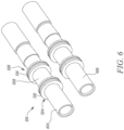
- First and second sleeves 410, 412 are concentrically coupled to first and second electrical sockets 404, 406 as shown in FIG. 6 .
- First sleeve 410 may be coupled to first electrical socket 404 by a press-fit assembly.
- the first sleeve 410 may also be coupled to the first electrical socket 404 through overmolding process.
- the first electrical socket 404 may be treated as a substrate material, and the first sleeve 410 may then be partially cover the first electrical socket 404.
- First sleeve 410 may also be coupled to first electrical socket 404 through any other mechanical joining means as well which maybe suitable for application with various aspects of present disclosure.
- charging connector 210 further includes manifold assembly 414.
- the manifold assembly 414 has a hollow structure to enclose various other components of charging connector 210.
- Manifold assembly 414 has an inlet conduit 512 and an outlet conduit 514.
- FIG. 7 shows a side cross-sectional view of charging connector 210 showing inlet conduit 512 and outlet conduit 514.
- One or more O-rings are provided between the first sleeve 410 and manifold assembly 414. As shown in FIG. 7 , a first O-ring 702 is between the first sleeve 410 and the manifold assembly 414, and a second O-ring 704 is between the second sleeve 412 and the manifold assembly 414.
- first O-ring 702 is between a raised profile 510 of the first sleeve 410 and the manifold assembly 414.
- second O-ring 704 is between the raised profile 510 of the first sleeve 410 and the manifold assembly 414.
- the first and second O-rings 702, 704 provide an effective coupling between the first sleeve 410 and manifold assembly 414 such that no fluid escapes from the hollow interior space 416 or the fluid-flow path.
- one or more O-rings may be provided between second sleeve 412 and manifold assembly 414.
- the first sleeve 410 is concentrically coupled to the first electrical socket 404 such that the first sleeve 410 partially, or fully, encloses first electrical socket 404.
- second sleeve 412 is concentrically coupled to the second electrical socket 406 such that the second sleeve 412 partially, or fully, encloses second electrical socket 406.
- First and second sleeves 410, 412 may be made of a thermally conducting plastic material such that heat generated by the electrical sockets 404, 406 is removed through sleeves 410, 412.
- Inlet conduit 512 is connected to the hollow interior space 416 defined between manifold assembly 414 and first and second sleeves 410, 412.
- the outlet conduit 514 is also connected to the hollow interior space 416 between the manifold assembly 414 and the first and second sleeves 410, 412.
- the inlet conduit 512, hollow interior space 416, and outlet conduit 514 together create a fluid-flow path 802.
- FIG. 8 shows fluid flow path 802 within manifold assembly 414.
- a cooling fluid may flow through fluid flow path 802 to transfer heat generated by the electrical sockets 404, 406 away from charging connector 210. Cooling fluid may enter manifold assembly 414 through inlet conduit 512. The cooling fluid then gets bifurcated into a first fluid stream 804 and a second fluid stream 806.
- the first fluid stream 804 flows around hollow interior space 416 (between the first sleeve 410 and the manifold assembly 414).
- the second fluid stream 806 flows around the hollow interior space 416 (between second sleeve 412 and manifold assembly 414).
- the cooling fluid is ethylene glycol.
- the cooling fluid is an electrically conducting fluid.
- Cooling fluid absorbs thermal energy from heat in the electrical sockets 404, 406.
- Sleeves 410, 412 are made of a thermally conducting, electrically insulating material. Heat from the electrical sockets 404, 406 is transferred to cooling fluid through sleeves 410, 412. After flowing around hollow interior space 416, the first fluid stream 804 and the second fluid stream 806 combine together upstream of outlet conduit 514 and flow outside of manifold assembly 414 through outlet conduit 514. Cooling fluid flowing out of manifold assembly 414 through outlet conduit 514 may be received by a reservoir (not shown) which may provide for heat exchanging arrangements. A heat exchanger may be provided to take away heat absorbed by cooling fluid. After rejecting absorbed heat, the cooling fluid may be recirculated back to inlet conduit 512 for further cooling of charging connector 210.
- FIG. 9 shows another component included by charging connector 210.
- a Printed Circuit Board Assembly (PCBA) 902 is thermally coupled to charging connector 210.
- PCBA 902 is a two-part structure.
- a first part of PCBA 904 is coupled to charging connector 210 such that the first part of PCBA 904 sits on top of electrical sockets 404, 406.
- a second part of PCBA 908 is connected to the first part of PCBA 904 through a rigid-flex PCB construction, or other similar interconnects.
- the two-part structure of PCBA 902 allows for a more efficient routing of electrical wires of charging connector 210, and overall size of charging connector 210 maybe conveniently reduced.
- FIG. 10 shows the charging connector 210 without electrical socket 406.
- Charging connector 210 includes a temperature sensor 1002. Temperature sensor 1002 is thermally coupled to electrical socket 406. Another temperature sensor (not shown) thermally coupled to the electrical socket 404 is provided under electrical socket 404. Thermal coupling of the temperature sensors provides a better sensing response for collecting temperature data through the temperature sensors.
- the charging connector 210 disclosed in the present disclosure provides efficient cooling of pair of the electrical sockets 404, 406 through fluid flow path 802 partially within manifold assembly 414. Cooling fluid flows through fluid flow path 802, removing heat from the electrical sockets 404, 406. The cooling fluid can later reject the heat through any suitable heat exchange arrangement.
- charging connector 210 may also be used in any other application area as well which may allow use of such a charging connector.
- joinder references e.g., attached, affixed, coupled, connected, and the like
- joinder references are only used to aid the reader's understanding of the present disclosure, and may not create limitations, particularly as to the position, orientation, or use of the systems and/or methods disclosed herein. Therefore, joinder references, if any, are to be construed broadly. Moreover, such joinder references do not necessarily infer that two elements are directly connected to each other.
Landscapes
- Engineering & Computer Science (AREA)
- Power Engineering (AREA)
- Transportation (AREA)
- Mechanical Engineering (AREA)
- Microelectronics & Electronic Packaging (AREA)
- Electric Propulsion And Braking For Vehicles (AREA)
- Drilling And Exploitation, And Mining Machines And Methods (AREA)
- Electron Sources, Ion Sources (AREA)
- Cable Accessories (AREA)
- Details Of Connecting Devices For Male And Female Coupling (AREA)
- Connector Housings Or Holding Contact Members (AREA)
Applications Claiming Priority (3)
| Application Number | Priority Date | Filing Date | Title |
|---|---|---|---|
| US15/928,307 US11084390B2 (en) | 2018-03-22 | 2018-03-22 | Liquid-cooled charging connector |
| PCT/IB2019/052239 WO2019180622A1 (en) | 2018-03-22 | 2019-03-19 | Liquid-cooled charging connector |
| EP19721736.7A EP3768546B1 (en) | 2018-03-22 | 2019-03-19 | Liquid-cooled charging connector |
Related Parent Applications (2)
| Application Number | Title | Priority Date | Filing Date |
|---|---|---|---|
| EP19721736.7A Division EP3768546B1 (en) | 2018-03-22 | 2019-03-19 | Liquid-cooled charging connector |
| EP19721736.7A Division-Into EP3768546B1 (en) | 2018-03-22 | 2019-03-19 | Liquid-cooled charging connector |
Publications (1)
| Publication Number | Publication Date |
|---|---|
| EP4147902A1 true EP4147902A1 (en) | 2023-03-15 |
Family
ID=66397301
Family Applications (2)
| Application Number | Title | Priority Date | Filing Date |
|---|---|---|---|
| EP19721736.7A Active EP3768546B1 (en) | 2018-03-22 | 2019-03-19 | Liquid-cooled charging connector |
| EP22203497.7A Pending EP4147902A1 (en) | 2018-03-22 | 2019-03-19 | Liquid-cooled charging connector |
Family Applications Before (1)
| Application Number | Title | Priority Date | Filing Date |
|---|---|---|---|
| EP19721736.7A Active EP3768546B1 (en) | 2018-03-22 | 2019-03-19 | Liquid-cooled charging connector |
Country Status (9)
| Country | Link |
|---|---|
| US (2) | US11084390B2 (zh) |
| EP (2) | EP3768546B1 (zh) |
| JP (1) | JP7049477B2 (zh) |
| KR (2) | KR102488784B1 (zh) |
| CN (2) | CN117021990A (zh) |
| ES (1) | ES2943262T3 (zh) |
| FI (1) | FI3768546T3 (zh) |
| PT (1) | PT3768546T (zh) |
| WO (1) | WO2019180622A1 (zh) |
Families Citing this family (20)
| Publication number | Priority date | Publication date | Assignee | Title |
|---|---|---|---|---|
| DE102016117011A1 (de) * | 2016-09-09 | 2018-03-15 | Itt Manufacturing Enterprises Llc | Elektrisch leitfähiges Kontaktelement für einen elektrischen Steckverbinder |
| GB201801455D0 (en) * | 2018-01-30 | 2018-03-14 | Cejn Ab | Multicoupling with control means |
| DE102018102207A1 (de) * | 2018-02-01 | 2019-08-01 | Dr. Ing. H.C. F. Porsche Aktiengesellschaft | Kraftfahrzeugladekabel |
| DE102018215875A1 (de) * | 2018-09-18 | 2020-03-19 | Bayerische Motoren Werke Aktiengesellschaft | Ladestrangeinrichtung für eine Batterie eines Kraftfahrzeugs |
| JP7103135B2 (ja) * | 2018-10-04 | 2022-07-20 | トヨタ自動車株式会社 | 充電装置 |
| KR102575157B1 (ko) * | 2018-10-23 | 2023-09-06 | 현대자동차주식회사 | 전기차 충전을 위한 커넥팅 시스템 |
| CH715611B1 (de) * | 2018-12-05 | 2022-05-13 | BRUGG eConnect AG | Anschlusselement zum elektrischen Anschliessen einer fluidkühlbaren Einzelleitung, fluidkühlbare Einzelleitungseinheit und Ladekabel. |
| US10988041B2 (en) * | 2019-03-27 | 2021-04-27 | Te Connectivity Corporation | Cable heat exchanger for a power connector |
| US11469531B2 (en) | 2019-07-19 | 2022-10-11 | Yazaki North America, Inc. | Liquid-cooled charging system for a vehicle |
| KR102428044B1 (ko) * | 2019-11-06 | 2022-08-02 | 엘에스전선 주식회사 | 전기차 충전용 케이블 어셈블리 |
| CN111002860A (zh) * | 2019-12-18 | 2020-04-14 | 重庆国翰能源发展有限公司 | 一种大功率充电桩温度智能监控系统 |
| CN110994229B (zh) * | 2020-01-08 | 2021-04-06 | 山东银浦动力科技有限公司 | 一种新能源汽车用散热充电枪 |
| DE102020128791A1 (de) * | 2020-11-02 | 2022-05-05 | Te Connectivity Germany Gmbh | Kühlfluidleitgehäuse sowie elektrisches Verbindersystem mit einem Kühlfluidleitgehäuse |
| US11951857B2 (en) * | 2020-11-04 | 2024-04-09 | Ford Global Technologies, Llc | Liquid cooled electrical connectors |
| WO2022216822A1 (en) * | 2021-04-08 | 2022-10-13 | Tesla, Inc. | Charging system with cooling system |
| CN113085608A (zh) * | 2021-04-30 | 2021-07-09 | 四川永贵科技有限公司 | 一种散热效果好的端子的液冷结构 |
| CN113147454A (zh) * | 2021-04-30 | 2021-07-23 | 四川永贵科技有限公司 | 一种全覆盖型端子的液冷结构 |
| EP4112366A1 (en) * | 2021-06-30 | 2023-01-04 | ABB E-mobility B.V. | Charging connector for an electric vehicle |
| CN114590145B (zh) * | 2022-03-31 | 2023-11-14 | 深圳市道通合创数字能源有限公司 | 电连接器、充电桩及充电系统 |
| DE102022109244A1 (de) * | 2022-04-14 | 2023-10-19 | Amphenol Tuchel Industrial GmbH | Steckverbinder |
Citations (4)
| Publication number | Priority date | Publication date | Assignee | Title |
|---|---|---|---|---|
| US20150217654A1 (en) * | 2014-02-05 | 2015-08-06 | Tesla Motors, Inc. | Cooling of charging cable |
| US20170144558A1 (en) * | 2015-11-19 | 2017-05-25 | Dr. Ing. H.C. F. Porsche Aktiengesellschaft | Electric line arrangement |
| WO2017133893A1 (en) * | 2016-02-01 | 2017-08-10 | Huber+Suhner Ag | Cable assembly |
| US20170338006A1 (en) * | 2016-05-20 | 2017-11-23 | Southwire Company, Llc | Liquid Cooled Charging Cable System |
Family Cites Families (18)
| Publication number | Priority date | Publication date | Assignee | Title |
|---|---|---|---|---|
| JP3347426B2 (ja) * | 1993-10-19 | 2002-11-20 | 本田技研工業株式会社 | 電動車両用充電器の冷却構造 |
| US5670860A (en) * | 1995-06-06 | 1997-09-23 | Hughes Electronics | High power, high frequency, liquid-cooled transmission cable and charging system |
| EP0982832A3 (en) * | 1996-08-07 | 2000-08-09 | Sumitomo Wiring Systems, Ltd. | Charging system for electric vehicle |
| CN103943912B (zh) * | 2008-11-12 | 2018-02-27 | 江森自控帅福得先进能源动力系统有限责任公司 | 具有热交换器的电池系统 |
| US9287646B2 (en) * | 2010-10-14 | 2016-03-15 | Gregory thomas mark | Actively cooled electrical connection |
| EP2765677B1 (en) * | 2011-10-04 | 2018-09-26 | Toyota Jidosha Kabushiki Kaisha | Charge control apparatus and charge control method |
| US9586497B2 (en) * | 2013-08-22 | 2017-03-07 | Lightening Energy | Electric vehicle recharging station including a battery bank |
| US9643510B2 (en) * | 2014-11-25 | 2017-05-09 | Atieva, Inc. | Battery pack charging protocol selection system |
| US10377264B2 (en) * | 2015-01-30 | 2019-08-13 | Ford Global Technologies, Llc | Vehicle conductive charge port having cooling infrastructure |
| DE102016105347A1 (de) * | 2016-03-22 | 2017-09-28 | Phoenix Contact E-Mobility Gmbh | Steckverbinderteil mit einem gekühlten Kontaktelement |
| DE102016105311A1 (de) * | 2016-03-22 | 2017-09-28 | Phoenix Contact E-Mobility Gmbh | Steckverbinderteil mit einem gekühlten Kontaktelement |
| DE102016204895B4 (de) * | 2016-03-23 | 2020-11-12 | Phoenix Contact E-Mobility Gmbh | Ladestecker mit einem Leistungskontaktsystem und Ladestation zur Abgabe elektrischer Energie an einen Empfänger elektrischer Energie |
| DE102016209607A1 (de) | 2016-06-01 | 2017-12-07 | Phoenix Contact E-Mobility Gmbh | Ladekabel zur Übertragung elektrischer Energie, Ladestecker und Ladestation zur Abgabe elektrischer Energie an einen Empfänger elektrischer Energie |
| DE102016117011A1 (de) * | 2016-09-09 | 2018-03-15 | Itt Manufacturing Enterprises Llc | Elektrisch leitfähiges Kontaktelement für einen elektrischen Steckverbinder |
| DE102016117261B3 (de) * | 2016-09-14 | 2017-11-30 | HARTING Automotive GmbH | System aus einem Steckverbinder, einem fluidgekühlten Kabel und einer Anschlusseinheit |
| CN106347166B (zh) * | 2016-11-22 | 2018-09-18 | 飞洲集团有限公司 | 一种电动车辆的整体冷却充电装置 |
| CN107425323B (zh) * | 2017-08-28 | 2022-07-05 | 深圳市沃尔新能源电气科技股份有限公司 | 一种插接母端子及应用该母端子的充电枪、充电枪用插座 |
| DE102017125265A1 (de) * | 2017-10-27 | 2019-05-02 | Phoenix Contact E-Mobility Gmbh | Ladestecker und Ladestation für ein Kraftfahrzeug |
-
2018
- 2018-03-22 US US15/928,307 patent/US11084390B2/en active Active
-
2019
- 2019-03-19 KR KR1020207029771A patent/KR102488784B1/ko active IP Right Grant
- 2019-03-19 ES ES19721736T patent/ES2943262T3/es active Active
- 2019-03-19 CN CN202311136010.3A patent/CN117021990A/zh active Pending
- 2019-03-19 WO PCT/IB2019/052239 patent/WO2019180622A1/en active Application Filing
- 2019-03-19 CN CN201980020614.7A patent/CN111936347B/zh active Active
- 2019-03-19 EP EP19721736.7A patent/EP3768546B1/en active Active
- 2019-03-19 KR KR1020237001031A patent/KR102606474B1/ko active IP Right Grant
- 2019-03-19 FI FIEP19721736.7T patent/FI3768546T3/fi active
- 2019-03-19 JP JP2020550732A patent/JP7049477B2/ja active Active
- 2019-03-19 PT PT197217367T patent/PT3768546T/pt unknown
- 2019-03-19 EP EP22203497.7A patent/EP4147902A1/en active Pending
-
2021
- 2021-07-09 US US17/305,554 patent/US20220037821A1/en active Pending
Patent Citations (4)
| Publication number | Priority date | Publication date | Assignee | Title |
|---|---|---|---|---|
| US20150217654A1 (en) * | 2014-02-05 | 2015-08-06 | Tesla Motors, Inc. | Cooling of charging cable |
| US20170144558A1 (en) * | 2015-11-19 | 2017-05-25 | Dr. Ing. H.C. F. Porsche Aktiengesellschaft | Electric line arrangement |
| WO2017133893A1 (en) * | 2016-02-01 | 2017-08-10 | Huber+Suhner Ag | Cable assembly |
| US20170338006A1 (en) * | 2016-05-20 | 2017-11-23 | Southwire Company, Llc | Liquid Cooled Charging Cable System |
Also Published As
| Publication number | Publication date |
|---|---|
| US20190291588A1 (en) | 2019-09-26 |
| CN111936347B (zh) | 2023-09-22 |
| KR102606474B1 (ko) | 2023-11-30 |
| PT3768546T (pt) | 2023-04-24 |
| EP3768546B1 (en) | 2023-03-15 |
| FI3768546T3 (fi) | 2023-06-06 |
| EP3768546A1 (en) | 2021-01-27 |
| CN111936347A (zh) | 2020-11-13 |
| CN117021990A (zh) | 2023-11-10 |
| ES2943262T3 (es) | 2023-06-12 |
| JP2021517716A (ja) | 2021-07-26 |
| KR102488784B1 (ko) | 2023-01-18 |
| KR20230010846A (ko) | 2023-01-19 |
| US20220037821A1 (en) | 2022-02-03 |
| KR20200130733A (ko) | 2020-11-19 |
| WO2019180622A1 (en) | 2019-09-26 |
| JP7049477B2 (ja) | 2022-04-06 |
| US11084390B2 (en) | 2021-08-10 |
Similar Documents
| Publication | Publication Date | Title |
|---|---|---|
| US20220037821A1 (en) | Liquid-cooled charging connector | |
| JP6721708B2 (ja) | 冷却された接点要素を具備するプラグインコネクタポート | |
| US9701210B2 (en) | Cooling of charging cable | |
| US11590855B2 (en) | Electric vehicle fast charging and battery cooling system using a charger cooled fluid-to-battery cooled fluid heat exchange device | |
| JP6637765B2 (ja) | 熱電ベースの熱管理システム | |
| US20220144115A1 (en) | Electrical Vehicle Charging System for Charging an Electrical Vehicle | |
| CN103429446B (zh) | 调节机动车辆部件温度的方法以及调节该部件温度的系统 | |
| CN109076717A (zh) | 使用液体冷却的充电连接器 | |
| EP2909893B1 (en) | Cooled power connector with shut off valve, induction heating system, and cable for use with connector | |
| CN109962430B (zh) | 线束单元、蓄电装置单元以及线束 | |
| US11433773B2 (en) | Charging harness unit for a battery of a motor vehicle | |
| JP7235458B2 (ja) | 電気接続デバイスおよびその冷却 | |
| JP2015520925A (ja) | バッテリモジュールの熱管理および接続装置 | |
| CN106067576A (zh) | 牵引电池总成 | |
| US11919411B2 (en) | Leak detection in a cable assembly | |
| CN106463602A (zh) | 用于热电组件中热电装置的绝缘子和连接器 | |
| EP0651404A1 (en) | Internal cooling of electric automobile charging transformer | |
| US20240123850A1 (en) | Charging Connector for an Electric Vehicle |
Legal Events
| Date | Code | Title | Description |
|---|---|---|---|
| PUAI | Public reference made under article 153(3) epc to a published international application that has entered the european phase |
Free format text: ORIGINAL CODE: 0009012 |
|
| STAA | Information on the status of an ep patent application or granted ep patent |
Free format text: STATUS: THE APPLICATION HAS BEEN PUBLISHED |
|
| AC | Divisional application: reference to earlier application |
Ref document number: 3768546 Country of ref document: EP Kind code of ref document: P |
|
| AK | Designated contracting states |
Kind code of ref document: A1 Designated state(s): AL AT BE BG CH CY CZ DE DK EE ES FI FR GB GR HR HU IE IS IT LI LT LU LV MC MK MT NL NO PL PT RO RS SE SI SK SM TR |
|
| STAA | Information on the status of an ep patent application or granted ep patent |
Free format text: STATUS: REQUEST FOR EXAMINATION WAS MADE |
|
| 17P | Request for examination filed |
Effective date: 20230908 |
|
| RBV | Designated contracting states (corrected) |
Designated state(s): AL AT BE BG CH CY CZ DE DK EE ES FI FR GB GR HR HU IE IS IT LI LT LU LV MC MK MT NL NO PL PT RO RS SE SI SK SM TR |