EP4147817A1 - Procede d'assemblage d'au moins une bague cooperant par frettage avec une portee de frettage d'une piece - Google Patents
Procede d'assemblage d'au moins une bague cooperant par frettage avec une portee de frettage d'une piece Download PDFInfo
- Publication number
- EP4147817A1 EP4147817A1 EP22194802.9A EP22194802A EP4147817A1 EP 4147817 A1 EP4147817 A1 EP 4147817A1 EP 22194802 A EP22194802 A EP 22194802A EP 4147817 A1 EP4147817 A1 EP 4147817A1
- Authority
- EP
- European Patent Office
- Prior art keywords
- ring
- shrinking
- expansion
- reference axis
- splines
- Prior art date
- Legal status (The legal status is an assumption and is not a legal conclusion. Google has not performed a legal analysis and makes no representation as to the accuracy of the status listed.)
- Pending
Links
Images



Classifications
-
- B—PERFORMING OPERATIONS; TRANSPORTING
- B23—MACHINE TOOLS; METAL-WORKING NOT OTHERWISE PROVIDED FOR
- B23P—METAL-WORKING NOT OTHERWISE PROVIDED FOR; COMBINED OPERATIONS; UNIVERSAL MACHINE TOOLS
- B23P11/00—Connecting or disconnecting metal parts or objects by metal-working techniques not otherwise provided for
- B23P11/005—Connecting or disconnecting metal parts or objects by metal-working techniques not otherwise provided for by expanding or crimping
-
- B—PERFORMING OPERATIONS; TRANSPORTING
- B23—MACHINE TOOLS; METAL-WORKING NOT OTHERWISE PROVIDED FOR
- B23P—METAL-WORKING NOT OTHERWISE PROVIDED FOR; COMBINED OPERATIONS; UNIVERSAL MACHINE TOOLS
- B23P11/00—Connecting or disconnecting metal parts or objects by metal-working techniques not otherwise provided for
- B23P11/02—Connecting or disconnecting metal parts or objects by metal-working techniques not otherwise provided for by first expanding and then shrinking or vice versa, e.g. by using pressure fluids; by making force fits
- B23P11/025—Connecting or disconnecting metal parts or objects by metal-working techniques not otherwise provided for by first expanding and then shrinking or vice versa, e.g. by using pressure fluids; by making force fits by using heat or cold
-
- B—PERFORMING OPERATIONS; TRANSPORTING
- B60—VEHICLES IN GENERAL
- B60B—VEHICLE WHEELS; CASTORS; AXLES FOR WHEELS OR CASTORS; INCREASING WHEEL ADHESION
- B60B27/00—Hubs
- B60B27/0015—Hubs for driven wheels
- B60B27/0021—Hubs for driven wheels characterised by torque transmission means from drive axle
- B60B27/0026—Hubs for driven wheels characterised by torque transmission means from drive axle of the radial type, e.g. splined key
-
- B—PERFORMING OPERATIONS; TRANSPORTING
- B60—VEHICLES IN GENERAL
- B60B—VEHICLE WHEELS; CASTORS; AXLES FOR WHEELS OR CASTORS; INCREASING WHEEL ADHESION
- B60B27/00—Hubs
- B60B27/0078—Hubs characterised by the fixation of bearings
-
- B—PERFORMING OPERATIONS; TRANSPORTING
- B60—VEHICLES IN GENERAL
- B60B—VEHICLE WHEELS; CASTORS; AXLES FOR WHEELS OR CASTORS; INCREASING WHEEL ADHESION
- B60B27/00—Hubs
- B60B27/0078—Hubs characterised by the fixation of bearings
- B60B27/0084—Hubs characterised by the fixation of bearings caulking to fix inner race
-
- F—MECHANICAL ENGINEERING; LIGHTING; HEATING; WEAPONS; BLASTING
- F16—ENGINEERING ELEMENTS AND UNITS; GENERAL MEASURES FOR PRODUCING AND MAINTAINING EFFECTIVE FUNCTIONING OF MACHINES OR INSTALLATIONS; THERMAL INSULATION IN GENERAL
- F16C—SHAFTS; FLEXIBLE SHAFTS; ELEMENTS OR CRANKSHAFT MECHANISMS; ROTARY BODIES OTHER THAN GEARING ELEMENTS; BEARINGS
- F16C33/00—Parts of bearings; Special methods for making bearings or parts thereof
- F16C33/30—Parts of ball or roller bearings
- F16C33/58—Raceways; Race rings
- F16C33/581—Raceways; Race rings integral with other parts, e.g. with housings or machine elements such as shafts or gear wheels
-
- F—MECHANICAL ENGINEERING; LIGHTING; HEATING; WEAPONS; BLASTING
- F16—ENGINEERING ELEMENTS AND UNITS; GENERAL MEASURES FOR PRODUCING AND MAINTAINING EFFECTIVE FUNCTIONING OF MACHINES OR INSTALLATIONS; THERMAL INSULATION IN GENERAL
- F16C—SHAFTS; FLEXIBLE SHAFTS; ELEMENTS OR CRANKSHAFT MECHANISMS; ROTARY BODIES OTHER THAN GEARING ELEMENTS; BEARINGS
- F16C35/00—Rigid support of bearing units; Housings, e.g. caps, covers
- F16C35/04—Rigid support of bearing units; Housings, e.g. caps, covers in the case of ball or roller bearings
- F16C35/06—Mounting or dismounting of ball or roller bearings; Fixing them onto shaft or in housing
- F16C35/063—Fixing them on the shaft
- F16C35/0635—Fixing them on the shaft the bore of the inner ring being of special non-cylindrical shape which co-operates with a complementary shape on the shaft, e.g. teeth, polygonal sections
-
- F—MECHANICAL ENGINEERING; LIGHTING; HEATING; WEAPONS; BLASTING
- F16—ENGINEERING ELEMENTS AND UNITS; GENERAL MEASURES FOR PRODUCING AND MAINTAINING EFFECTIVE FUNCTIONING OF MACHINES OR INSTALLATIONS; THERMAL INSULATION IN GENERAL
- F16C—SHAFTS; FLEXIBLE SHAFTS; ELEMENTS OR CRANKSHAFT MECHANISMS; ROTARY BODIES OTHER THAN GEARING ELEMENTS; BEARINGS
- F16C43/00—Assembling bearings
- F16C43/04—Assembling rolling-contact bearings
-
- B—PERFORMING OPERATIONS; TRANSPORTING
- B60—VEHICLES IN GENERAL
- B60B—VEHICLE WHEELS; CASTORS; AXLES FOR WHEELS OR CASTORS; INCREASING WHEEL ADHESION
- B60B2310/00—Manufacturing methods
- B60B2310/30—Manufacturing methods joining
-
- B—PERFORMING OPERATIONS; TRANSPORTING
- B60—VEHICLES IN GENERAL
- B60B—VEHICLE WHEELS; CASTORS; AXLES FOR WHEELS OR CASTORS; INCREASING WHEEL ADHESION
- B60B2310/00—Manufacturing methods
- B60B2310/30—Manufacturing methods joining
- B60B2310/314—Manufacturing methods joining by deformation
-
- B—PERFORMING OPERATIONS; TRANSPORTING
- B60—VEHICLES IN GENERAL
- B60B—VEHICLE WHEELS; CASTORS; AXLES FOR WHEELS OR CASTORS; INCREASING WHEEL ADHESION
- B60B2310/00—Manufacturing methods
- B60B2310/30—Manufacturing methods joining
- B60B2310/316—Manufacturing methods joining by press-fitting, shrink-fitting
-
- F—MECHANICAL ENGINEERING; LIGHTING; HEATING; WEAPONS; BLASTING
- F16—ENGINEERING ELEMENTS AND UNITS; GENERAL MEASURES FOR PRODUCING AND MAINTAINING EFFECTIVE FUNCTIONING OF MACHINES OR INSTALLATIONS; THERMAL INSULATION IN GENERAL
- F16C—SHAFTS; FLEXIBLE SHAFTS; ELEMENTS OR CRANKSHAFT MECHANISMS; ROTARY BODIES OTHER THAN GEARING ELEMENTS; BEARINGS
- F16C19/00—Bearings with rolling contact, for exclusively rotary movement
- F16C19/02—Bearings with rolling contact, for exclusively rotary movement with bearing balls essentially of the same size in one or more circular rows
- F16C19/14—Bearings with rolling contact, for exclusively rotary movement with bearing balls essentially of the same size in one or more circular rows for both radial and axial load
- F16C19/18—Bearings with rolling contact, for exclusively rotary movement with bearing balls essentially of the same size in one or more circular rows for both radial and axial load with two or more rows of balls
- F16C19/181—Bearings with rolling contact, for exclusively rotary movement with bearing balls essentially of the same size in one or more circular rows for both radial and axial load with two or more rows of balls with angular contact
- F16C19/183—Bearings with rolling contact, for exclusively rotary movement with bearing balls essentially of the same size in one or more circular rows for both radial and axial load with two or more rows of balls with angular contact with two rows at opposite angles
- F16C19/184—Bearings with rolling contact, for exclusively rotary movement with bearing balls essentially of the same size in one or more circular rows for both radial and axial load with two or more rows of balls with angular contact with two rows at opposite angles in O-arrangement
-
- F—MECHANICAL ENGINEERING; LIGHTING; HEATING; WEAPONS; BLASTING
- F16—ENGINEERING ELEMENTS AND UNITS; GENERAL MEASURES FOR PRODUCING AND MAINTAINING EFFECTIVE FUNCTIONING OF MACHINES OR INSTALLATIONS; THERMAL INSULATION IN GENERAL
- F16C—SHAFTS; FLEXIBLE SHAFTS; ELEMENTS OR CRANKSHAFT MECHANISMS; ROTARY BODIES OTHER THAN GEARING ELEMENTS; BEARINGS
- F16C2226/00—Joining parts; Fastening; Assembling or mounting parts
- F16C2226/10—Force connections, e.g. clamping
- F16C2226/12—Force connections, e.g. clamping by press-fit, e.g. plug-in
-
- F—MECHANICAL ENGINEERING; LIGHTING; HEATING; WEAPONS; BLASTING
- F16—ENGINEERING ELEMENTS AND UNITS; GENERAL MEASURES FOR PRODUCING AND MAINTAINING EFFECTIVE FUNCTIONING OF MACHINES OR INSTALLATIONS; THERMAL INSULATION IN GENERAL
- F16C—SHAFTS; FLEXIBLE SHAFTS; ELEMENTS OR CRANKSHAFT MECHANISMS; ROTARY BODIES OTHER THAN GEARING ELEMENTS; BEARINGS
- F16C2226/00—Joining parts; Fastening; Assembling or mounting parts
- F16C2226/50—Positive connections
- F16C2226/52—Positive connections with plastic deformation, e.g. caulking or staking
-
- F—MECHANICAL ENGINEERING; LIGHTING; HEATING; WEAPONS; BLASTING
- F16—ENGINEERING ELEMENTS AND UNITS; GENERAL MEASURES FOR PRODUCING AND MAINTAINING EFFECTIVE FUNCTIONING OF MACHINES OR INSTALLATIONS; THERMAL INSULATION IN GENERAL
- F16C—SHAFTS; FLEXIBLE SHAFTS; ELEMENTS OR CRANKSHAFT MECHANISMS; ROTARY BODIES OTHER THAN GEARING ELEMENTS; BEARINGS
- F16C2226/00—Joining parts; Fastening; Assembling or mounting parts
- F16C2226/50—Positive connections
- F16C2226/80—Positive connections with splines, serrations or similar profiles to prevent movement between joined parts
-
- F—MECHANICAL ENGINEERING; LIGHTING; HEATING; WEAPONS; BLASTING
- F16—ENGINEERING ELEMENTS AND UNITS; GENERAL MEASURES FOR PRODUCING AND MAINTAINING EFFECTIVE FUNCTIONING OF MACHINES OR INSTALLATIONS; THERMAL INSULATION IN GENERAL
- F16C—SHAFTS; FLEXIBLE SHAFTS; ELEMENTS OR CRANKSHAFT MECHANISMS; ROTARY BODIES OTHER THAN GEARING ELEMENTS; BEARINGS
- F16C2326/00—Articles relating to transporting
- F16C2326/01—Parts of vehicles in general
- F16C2326/02—Wheel hubs or castors
-
- F—MECHANICAL ENGINEERING; LIGHTING; HEATING; WEAPONS; BLASTING
- F16—ENGINEERING ELEMENTS AND UNITS; GENERAL MEASURES FOR PRODUCING AND MAINTAINING EFFECTIVE FUNCTIONING OF MACHINES OR INSTALLATIONS; THERMAL INSULATION IN GENERAL
- F16D—COUPLINGS FOR TRANSMITTING ROTATION; CLUTCHES; BRAKES
- F16D1/00—Couplings for rigidly connecting two coaxial shafts or other movable machine elements
- F16D1/10—Quick-acting couplings in which the parts are connected by simply bringing them together axially
- F16D2001/103—Quick-acting couplings in which the parts are connected by simply bringing them together axially the torque is transmitted via splined connections
-
- F—MECHANICAL ENGINEERING; LIGHTING; HEATING; WEAPONS; BLASTING
- F16—ENGINEERING ELEMENTS AND UNITS; GENERAL MEASURES FOR PRODUCING AND MAINTAINING EFFECTIVE FUNCTIONING OF MACHINES OR INSTALLATIONS; THERMAL INSULATION IN GENERAL
- F16D—COUPLINGS FOR TRANSMITTING ROTATION; CLUTCHES; BRAKES
- F16D2250/00—Manufacturing; Assembly
- F16D2250/003—Chip removing
Definitions
- the invention relates, in general, to the technical field of the assembly of mechanical parts.
- the invention relates more specifically to the assembly of a part such as a driving wheel hub of a vehicle on a transmission bowl.
- this bearing comprises an outer ring, two rows of rolling bodies and at least one inner ring fitted onto the hub so that this inner ring comes into axial abutment against a shoulder of a bearing surface of the hub.
- the rolling bodies of a row roll on one of the raceways of the outer ring and the raceway of the inner ring. Those of the other row roll on the other race of the outer race and the race of the hub or a second inner race.
- the so-called inner ring(s) is (are) fitted onto the hub.
- the inner ring(s) is (are) immobilized radially by fitting onto the hub. Furthermore, the bearing is immobilized axially in one direction by its bearing against the shoulder of the hub and axially in the other direction by an annular flange formed by plastic deformation of a part of the hub on which is mounted the inner ring to be maintained. , or possibly by the transmission bowl.
- This flange, or this transmission bowl has a retention face applied under pressure to the upper face of the ring, so as to immobilize the ring axially, in axial thrust against the shoulder of a bearing surface of the hub.
- the wheel hub consists of a part defining a geometric axis of rotation and having an axial cavity provided with splines on an internal wall for torque transmission purposes. Indeed, these splines make it possible to carry out the coupling with the transmission bowl and thus to ensure the function of passage of the torque to the wheels.
- the axial cavity of the hub is open at one end where the inner ring retention device is located, this same opening being configured to allow the entry of a splined axis of the transmission bowl cooperating with the internal splines of the cavity axial of the hub when the transmission bowl is assembled with the hub.
- a broaching operation to obtain the splines can be performed on the hub alone, before assembly of the bearing. This is the case for example in the solution described in the patent US 7,707,724 B2 . But in this case, the fact of assembling the bearing after the splines have been produced has the effect of shrinking the splines and deteriorating the geometric precision, in particular the straightness, of these splines. This even when a constraint operation of the shrunken zone is carried out during the broaching operation.
- the invention aims to remedy all or part of the drawbacks of the state of the art by proposing in particular a method of manufacturing an assembly of at least one bearing ring on a driving wheel hub making it possible to limit any deterioration of the straightness of the splines after forming so as to guarantee perfect transmission of the torque between the transmission bowl and the wheel hub, and to ensure easy assembly of these two components together.
- an “elasto-plastic” expansion is understood to mean an expansion which evolves first as an elastic deformation and then as a plastic deformation. In this way, once the radial elastoplastic expansion of the upper portion of the part has been carried out, the part does not return to its initial shape and retains a widening of both the shrinking surface and the portion of the grooves.
- Such a method makes it possible to carry out the step of radial expansion independently of the operation for producing the splines: this has the direct advantage of being able to carry out this method independently of other steps that can be implemented by other devices. possibly or in different places.
- Another advantage provided by such a method is the possibility of more faithfully adapting the need for anticipating the shrinkage by adjusting the elasto-plastic deformation necessary according to the type of bearing, whatever the axial holding device of the inner ring(s) on the part.
- This deformation adjustment can be predetermined in particular from successive tests and take into account the effects of the various subsequent stages which will have an impact on the deformation of the upper portion
- the portion of the splines comprises, or even consists of, a portion in at least partial axial overlap with the hooping surface.
- the part is in one piece.
- the part is metallic, preferably formed based on steel, preferably again made of steel.
- a material is chosen for its structural characteristics as well as for its elasto-plastic behavior.
- the radial elastoplastic expansion of the upper portion of the part deforms at least one cylindrical portion of the axial cavity having a nominal diameter taken before expansion into a flared portion, a smaller diameter of which taken after expansion on the same cylindrical portion is greater than or equal to the nominal diameter of said cylindrical portion taken before expansion.
- a continuous control of the expansion is carried out, the step of radial elastoplastic expansion of the upper portion of the part being preferably controlled according to the data of the continuous control carried out. In this way, the elastoplastic expansion stage is perfectly controlled.
- the radial elastoplastic expansion of the upper portion of the part is located axially between the shoulder of the bearing surface of the part and the free upper end.
- the axial cavity has at least one change in internal diameter located axially between the shoulder of the cylindrical bearing surface of the part and the free upper end, and oriented in the direction of a reduction in thickness of the cylindrical bearing surface directed towards the free upper end.
- the radial elastoplastic expansion step comprises the use of a radial expansion tool, in particular for converting axial displacement into radial expansion displacement, preferably a step for placing of a plurality of expansion segments through the free upper end and distributed around an expansion cone and a step of applying an axial force to the expansion cone.
- a radial expansion tool in particular for converting axial displacement into radial expansion displacement, preferably a step for placing of a plurality of expansion segments through the free upper end and distributed around an expansion cone and a step of applying an axial force to the expansion cone.
- other elasto-plastic expansion methods can be used, for example: by direct pressing (axial force) of a shaped expansion tool (for example cone) on the zone to be flared; by introducing a tool implementing a pressurized fluid to carry out the expansion of an expansion tool; or any other method to ensure the targeted deformation.
- the step of forming open splines on the inner wall is a broaching step.
- the inner wall is an inner wall of revolution.
- the assembly method comprises, after the step of shrink-fitting the ring, a step of forming an annular collar from the free upper end of the part, the annular collar having a side retainer applied to the upper transverse face of the ring, so as to immobilize the ring axially, in axial support against the shoulder of the bearing surface of the part.
- a screwed transmission can be provided which would bear against the ring instead of the annular flange.
- the step of forming the annular collar has the effect of a local deformation of the upper portion such that the portion of the splines, for example overlapping with the shrinking surface, approaches the reference axis .
- the step of radial elastoplastic expansion of the upper portion of the part is configured so as to take into account this step of deformation of the upper portion in addition to the step of subsequent shrinking of the ring on the hooping surface so that, once the assembly process is completed, the splines are as straight as possible despite the deformations undergone through the various stages of the assembly process implemented.
- the step of forming the annular flange comprises a crimping step, preferably an orbital crimping step.
- This orbital crimping step is also sometimes referred to as “bouterollage”.
- the step of shrinking the ring on the shrinking surface of the part is configured so that the lower transverse face of the ring comes into abutment against a shoulder of the part but also that the upper free end of the part protrudes axially from an upper transverse face of the ring.
- the annular flange can thus be formed from this part protruding from the free upper end of the part.
- the step of radial elastoplastic expansion of the upper portion of the part is configured so as to obtain a predetermined widening both of the shrinking surface and of the portion of the grooves, for example overlapping with the shrinking range.
- This widening is predetermined in depending on the subsequent steps tending to locally deform the upper portion such as the portion of the splines, for example overlapping with the shrinking surface, in the direction of bringing the reference axis closer together, and in order to obtain an assembly whose the grooves are as rectilinear as possible.
- the ring is an inner ring of a bearing and the part is a hub, preferably a driving wheel hub.
- the invention also relates to a part, in particular a motor vehicle drive wheel hub, intended to be assembled with at least one ring according to the assembly method as described above, the part comprising a shrinking surface defining an axis reference and having a through axial cavity, the shrink-fitting surface being configured to receive at least one shrink-fit ring and being turned radially opposite the reference axis, the part having a free upper end and an inner wall extending around the reference axis facing radially towards the reference axis and extending axially by delimiting at least part of the axial cavity, the part comprising grooves extending axially on the internal wall, the part being remarkable in that it comprises an upper portion expanded radially and in an elastoplastic manner, provided with a widening and with the hooping surface and with the portion of the splines.
- the invention also relates to an assembly, such as a kit, comprising a part as described above, in particular a motor vehicle drive wheel hub, and at least one ring configured to cooperate by shrinking with a shrinking surface of the part the assembly being remarkable in that it is configured so that in an assembled position, the ring is shrunk on the shrinking surface of the part so that a lower transverse face of the ring comes into abutment against a shoulder of the part, the shrinking of the ring on the shrinking surface causing a deformation of the upper portion such that the portion of the splines approaches the reference axis.
- an assembly such as a kit, comprising a part as described above, in particular a motor vehicle drive wheel hub, and at least one ring configured to cooperate by shrinking with a shrinking surface of the part the assembly being remarkable in that it is configured so that in an assembled position, the ring is shrunk on the shrinking surface of the part so that a lower transverse face of the ring comes into abutment against a shoulder
- the latter relates to an assembly of a part and a shrunk ring on a hooping surface of the part, the assembly being characterized in that it is obtained directly by the process as described above.
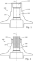
- FIG. 1 On the figures 1 to 5 is illustrated in longitudinal section of a part 100 forming a driving wheel hub of a motor vehicle during different stages of a method of assembling a ring 10 on this hub 100, the ring being an inner ring 10 of a rolling.
- the assembly 1 of the inner ring 10 and the hub 100 belongs to a rotating assembly intended to be guided in rotation about a geometric axis of rotation X with respect to a suspension member (not shown) at the bearing aid.
- Such a bearing generally consists in the example of an outer ring with two outer raceways, a first inner raceway 131 directly formed on the constituent part of the hub 100, and a second inner raceway 132 formed on the inner race 10 of the bearing fitted onto a cylindrical bearing surface 110 of the hub 100, rolling bodies (not shown) in two rows, for example balls, being interposed between the raceways.
- the outer ring generally comprises a fixing flange provided with an interface for fixing to the suspension member, comprising for example holes for inserting screws for fixing to the suspension member.
- the part 100 defines a reference axis X and has an axial cavity 120 passing through.
- the hooping surface 110 here cylindrical, on which the ring 10 is hooped is turned radially opposite the reference axis X.
- An inner wall 102 radially opposite to the hooping surface 110, is turned radially towards the reference axis X and extends around the reference axis X and axially along this axis X so as to present an at least partial axial overlap with the hooping surface 110.
- the hub 100 is intended to be driven in rotation by a transmission kinematic chain output member, constituted in particular by a transmission joint bowl (not shown), which can be homokinetic or quasi-homokinetic.
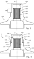
- the part constituting the bowl is provided with a splined shaft section intended to be inserted into the axial cavity 120 of mating shape made in the hub 100, in particular in the splines 103 extending axially on the inner wall 102 of the axial cavity 120 (see the figure 3 [Fig.3 ]).
- a step of forming, on the inner wall 102, axial grooves 103 is carried out.
- the step of forming splines 103 open on the inner wall 102 of revolution is a broaching step.
- a splined broaching tool 240 is forcibly inserted into the axial cavity 120 contributing to machining of the latter by broaching.
- the chips generated by the forced penetration of the broaching tool 240 into the cavity 120 are evacuated without difficulty through a wide opening at a lower end of the cavity 120, axially opposite to a free upper end 101 defining an open opening axially and allowing access to the broaching tool 240.
- the broaching tool 240 comprises a broach, for example made of steel, provided with a series of teeth whose section corresponds to the profile to be executed.
- the spindle length is defined by the number of teeth, itself defined by the amount of material to remove. In general, each tooth removes a thickness of metal varying from 0.03 to 0.01 mm depending on its shape and precise section.
- the hub 100 is configured so that the splines 103 have a portion 104, which is here in at least partial axial overlap with the shrinking surface 110 (see the figure 3 [Fig.3 ]). Once the splines 103 have been made, the hub 100 therefore comprises a portion 104 extending axially along which a corresponding portion of the splines 103 is superposed radially with a corresponding portion of the shrinking surface 110.
- FIG. 4 illustrates a step of shrinking the ring 10 on the shrinking surface 110 of the part 100 so that a lower transverse face 11 of the ring 10 comes into abutment against a shoulder 105 of the part 100.
- FIG.5 On the figure 5 ([Fig.5 ]), it is observed that an upper axial annular end 101 of the hub 100 has been folded radially outwards and preferably axially towards the inner ring 10 after fitting, in particular after fitting, of the inner ring 10 .
- This figure 5 illustrates the assembly 1 resulting from a step subsequent to the step of shrinking the ring 10, namely a step of forming an annular flange 107 from the free upper end 101 of the part 100.
- the annular collar 107 thus formed has a retention face 108 applied to the upper transverse face 12 of the ring 10, so as to axially immobilize the ring 10, in axial abutment against the shoulder 105 of the bearing surface 110 of the part 100 d one side and bearing against the collar 107 on the other side axially.
- This step of forming the annular collar 107 is carried out by material deformation, preferably using a rivet, if necessary after local heating of the thus deformed part forming the collar 107.
- This is in particular a crimping step, in particular orbital crimping.
- the hooping operation of the ring 10 on the hooping surface 110 of the part 100 like that of orbital crimping to form the flange 107 have this in common that they each have the effect of causing a deformation of the upper portion 106, comprising in particular the portion 104 of the splines 103 here overlapping with the hooping surface 110, this deformation being oriented in the direction of bringing the upper portion 106 closer to the reference axis X.
- the operation of shrinking the ring 10 causes a shrinkage of the upper portion 106.
- this operation generally increases this shrinkage. This consequence is particularly visible on the Fig. 6B ([Fig.
- FIG. 6B which illustrates a graph on which are represented curves of the dimensional impacts of the steps of broaching C1 , shrinking C3 and orbital crimping C4 taken successively on the splined portion 103 of the hub 100, these curves being presented in perspective with the Fig. 6A ([Fig. 6A ]) which illustrates a more detailed sectional view of the splined portion 103 of the hub 100.
- the graph has as abscissa an axial position datum of the splined portion 103 of the hub 100 in millimeters and as the ordinate the measurement of the difference in diameter in microns.
- the assembly 1 obtained is designed to receive in the axial cavity 120 a splined shaft section of the transmission seal bowl. This cooperation of this splined shaft in the corresponding splined axial cavity makes it possible to oppose a relative rotation of the two parts and thus allow the transmission of torque during use of the vehicle.
- the hub 100 is configured to also participate in the axial locking of the bowl.
- the axial cavity 120 is in particular sized to be crossed by a constituent part of the bowl provided with a threaded or tapped end to accommodate a tapped or threaded body of a screw or a nut, the screw having a head coming to be pressed against a washer which bears against an annular surface 125 of the hub 100, forming a circular crown surrounding the axial cavity 120 at its lower end.
- an annular face of the bowl bears against a corresponding face of the hub 100 constituted by the flange 107.
- a step of radial elasto-plastic expansion of an upper portion 106 of part 100 is produced.
- Such an operation makes it possible to create a widening of the upper portion 106 of the hub 100, and in particular of both the shrinking surface 110 and the portion 104 of the splines 103, in particular overlapping with the shrinking surface 110.
- the maximum resultant radial expansion is located at the upper end 101 free.
- the maximum radial expansion measured in line with the upper end 101 can reach, or even exceed, 200 microns.
- the necessary radial expansion is predetermined and linked to the deformation observed during the broaching and shrinking steps.
- This elasto-plastic expansion step is followed by a step of machining, or even of rectification of the hooping surface 110 prior to the hooping step.
- the subsequent hooping of the ring 10 on the hooping surface 110 participates, at least in part, in causing a deformation of the upper portion 106 such that the portion 104 of the splines 103 here overlapping with the hooping surface 110 approaches the reference axis X.
- the shrinking step can constitute the only deformation step in approach towards the reference axis X.
- the step of radial elastoplastic expansion is configured so as to take into account the deformation in approach towards the reference axis X brought subsequently by this step of forming the collar 107.
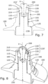
- FIG. 7 illustrates sectional views, one of which is in isometric perspective, of the hub 100 during such a step of radial elasto-plastic expansion of the upper portion 106 of the part 100 by means of a Expander 200.
- This expander tool 200 is configured to convert axial displacement into radial displacement.
- the expansion tool 200 se consists in particular of a support 230, of a plurality of expansion segments 220 through the free upper end 101 and distributed around an expansion cone 210 thanks to which an axial force can be applied to the cone of expansion 210 which itself applies a force to the expansion segments 220 .
- the set of expansion segments 220 is configured so as to form an annular assembly comprising the expansion segments 220 distributed around the expansion cone 210.
- the upper portion 106 of the part 100 has a cylindrical inner contact surface carried by the axial cavity 120 coaxial with the reference axis X and oriented on the side of the reference axis X.
- This inner radial contact surface is located axially between an upper end of the splines 103 of the splined portion and the free upper end 101.
- the axial transition between the upper end of the splines 103 of the splined portion and the inner contact surface is marked by a change in internal diameter 121 extending in a generally annular, discontinuous or continuous manner.
- This change in internal diameter 121 is moreover located axially between the shoulder 105 of the cylindrical bearing surface 110 of the part 100 and the free upper end 101 , the change in internal diameter 121 being oriented in the direction of a reduction of a thickness of the wall of the hub 100 directed towards the upper end 101 free.
- the support 230 is placed through the axial cavity of the hub by a lower part of the hub 100, axially opposite to the upper portion 106.
- a radially widened base of this support 230 is dimensioned so as to come into axial support against the annular surface 125 of the hub 100 in the expanded position.
- the support 230 also comprises a shaft to be inserted into the axial cavity 120.
- An upper portion of this shaft has a stop interface making it possible to provide a limit stop of an axial travel of the segments 220 of expansion distributed around the expansion cone 210 during the expansion operation.
- the support 230 has a recess open axially at its distal end on the side of the expansion cone 210. This axial recess makes it possible to guarantee the axial travel of the expansion cone 210.
- the support 230 is inserted into the axial cavity by the lower part of the hub 100 positioned vertically until it comes into abutment axial against the hub 100, in particular via its widened base which bears against the annular surface 125 of the hub 100 of greater radial dimension than that of the axial cavity 120.
- each expansion segment 220 is then placed in the upper portion 106 through the upper free end 101 , each expansion segment 220 being positioned so as to come, on the one hand, radially into contact and bearing against a part of the cylindrical radial contact surface of the upper portion 106 carried by the axial cavity 120, and on the other hand, axially resting against a bearing surface of the distal end of the support 230.
- the expansion segments 220 arranged form an annular assembly 220' in which a segment 220 taken alone corresponds to a portion of this annular assembly over a predetermined angular sector.
- This annular assembly 220' has an outer radial surface 221' formed by the circumferential series of the individual outer surfaces of the segments 220 and a radially inner surface 222' delimiting a space to accommodate the expansion cone 210.
- This inner surface extends from so as to form a surface of revolution around the reference axis X frustoconical in the direction of a reduction in its diameter towards the interior of the axial cavity 120, this interior surface being formed by the globally continuous circumferential series of interior surfaces individual segments 220 along an associated angular sector.
- the hub 100 is preferably oriented so that its reference axis X is placed vertically, the upper portion 106 of the part 100 being raised vertically upwards.
- Such a configuration facilitates and simplifies the implementation of the method by limiting the tools used and by skillfully using the forces of gravity to ensure the stability, in particular of the part 100 and the support 230.
- At least one spring 223 is arranged annularly so as to radially surround all of the segments 220.
- At least one circular groove 224 may be provided for this purpose by surrounding the outer radial surface 221′ carried by the set of segments 220.
- Such a spring 223 aims to maintain a unity of the set of segments 220 by constraining radially inwards, i.e. towards the reference axis X in the assembly position. This in particular facilitates the manipulation of the segments 220 in particular when they are placed in the upper portion 106 of the axial cavity 120 through the upper end 101 free.
- the expansion cone 210 which in reality has a globally frustoconical outer shape complementary to the shape delimited by the radially inner surface 222' of the annular assembly 220' , is used to apply an axial force to the inner surface 222'.
- the sliding of the two frustoconical surfaces generates a force on the annular assembly 220' having an axial component and a radial component.
- the installation of the expansion cone 210 and of the segments 220 can be concomitant, this all the more so if the annular assembly 220' is, on the one hand, held radially in abutment against the expansion cone 210 thanks to the annular spring surrounding the annular assembly 220 ', and on the other hand, held axially on the expansion cone 210 thanks to the tapered shape in one direction and by a flange projecting annularly with respect to a small base of the expansion cone 210 in the other direction.
- the axial component of the force is taken up by the support 230, against the flat bearing surface delimiting the distal end of the support 230 and contained in a plane orthogonal to the reference axis X.
- the flat bearing surface delimiting the distal end of the support 230 is generally located axially closer to the free upper end 101 than to the upper end of the splines 103 of the splined portion, and more generally to the diameter change 121 so as to avoid that, in view of of the configuration of the expansion tool 200 and the support 230, the segments 220 come into contact or interact with the splines 103 of the splined portion.
- the axial resultant of the forces is therefore taken up by the support 230.
- the radial component of the force is taken up for its part by the upper portion 106 carried by the axial cavity 120, from which it results, with a sufficient predetermined force, a widening and of the hooping surface 110 and of the portion 104 of the splines 103 at least overlapping with the shrinking surface 110.
- This flare is illustrated on the figure 9 ([Fig.9 ]) and the figure 10 ([Fig.10 ]) by dotted lines of the associated upper portion 106 and is located axially globally between the shoulder 105 of the shrinking surface 110 of the part 100 and the free upper end 101 .
- the radial elasto-plastic expansion of the upper portion 106 of the part 100 thus deforms at least one generally cylindrical portion of the axial cavity 120 having an average nominal diameter Dn taken before expansion into a flared portion including a smaller diameter Ds taken after expansion on the same cylindrical portion is greater than or equal to the nominal diameter Dn of said cylindrical portion taken before expansion.
- the radial expansion is elasto-plastic, that is to say that it evolves first as an elastic deformation then secondly as a plastic deformation, while presenting, if necessary, an elastic return after relaxation of the expansion effort, without however returning to its original position before expansion. In order not to degrade the hub, this plastic deformation must be perfectly controlled.
- the control of the deformation is ensured by a continuous control of the expansion carried out during the radial expansion operation of the upper portion 106 of the part 100, the expansion operation preferably being slaved according to the data of the continuous control carried out, this servo-control also preferably being continuous.
- FIG.11B illustrates a graph on which are represented the curves of the dimensional impacts of the steps of broaching C1 , of expansion C2', of hooping C3' then of orbital crimping C4' on the splined portion 103 of the hub 100, these curves being presented in outlook with the figure 11A ([Fig.11A ]) which illustrates a more detailed sectional view of the splined portion 103 of the hub 100.
- the expansion operation is carried out tending to widen the upper portion 106.
- the following hoop and crimping operations tend to deform the upper portion 106 in the direction of a approximation towards the reference axis X, in particular the hooping surface 110, thus making it possible to guarantee, on the one hand, the correct attachment of the ring 10 to the hooping surface 110 as well as, on the other hand, a straightness of the splines 103 very close original splines, just after the broaching operation.
- a machining operation can be implemented between the expansion and shrinking operations, to allow the assembly of the ring, in particular when the expansion results in a shrinking diameter greater than the inside diameter of the ring.
- the graph shows the change in the straightness of the splines over the operations carried out: curve C1 illustrates the straightness of the splines 103 obtained after the broaching operation; the curve C2' illustrates the straightness of the splines 103 after a subsequent elastoplastic expansion operation, the curve C3' illustrates the straightness of the splines 103 after the successive operation of shrinking the inner ring 10 , then finally the curve C4' illustrates the final straightness of the flutes 103 after the crimping operation.
- the assembly process is configured so that the difference in diameter of the axial cavity 120 taken in line with the splines 103 on the one hand, before the step of radial elastoplastic expansion of the upper portion 106 and, on the other hand, once the assembly process with the ring 10 has been implemented, in a configuration where the assembly 1 is ready to be coupled with the transmission bowl (after shrinking the ring 10, and the if necessary crimping for example), is less than 20 ⁇ m.
- a measurement is carried out for example using a ball sensing system.
- the part 100 comprises an upper portion 106 expanded radially and in an elasto-plastic way, provided with a flare and the hooping surface 110 and the portion of the splines 103 overlapping with the hooping surface 110.
- the ring 10 is shrunk on the shrinking surface 110 of the part 100 so that a lower transverse face 11 of the ring comes into abutment against a shoulder 105 of the part 100 and the upper end 101 free of the part protrudes axially from an upper transverse face 12 of the ring 10 for the embodiment described here, the shrink-fit surface 110 preferably being at least partly machined, depending on the subsequent operations, the shrink-fit at least the ring 10 on the hooping surface 100 causing an elastic deformation of the upper portion 106 such that the portion 104 of the splines 103 at least overlapping with the hooping surface 110 approaches the reference axis X.
- the shrinking step can comprise the shrinking of several rings 10, for example two rings 10, on the shrinking surface 110 of the part 100.
- the rings 10 are placed successively, coaxially with respect to the reference axis X.
- only one of these rings 10, for example a first ring will have a lower transverse face 11 which comes into abutment against a shoulder 105 of the part 100.
- a second ring has a lower face lower transverse 11 which may or may not come into abutment against an upper face of the first of the rings 10.
Landscapes
- Engineering & Computer Science (AREA)
- Mechanical Engineering (AREA)
- General Engineering & Computer Science (AREA)
- Mechanical Operated Clutches (AREA)
- Rolling Contact Bearings (AREA)
- Mounting Of Bearings Or Others (AREA)
- Lining Or Joining Of Plastics Or The Like (AREA)
Applications Claiming Priority (1)
| Application Number | Priority Date | Filing Date | Title |
|---|---|---|---|
| FR2109513A FR3126900B1 (fr) | 2021-09-10 | 2021-09-10 | Procédé d’assemblage d’au moins une bague coopérant par frettage avec une portée de frettage d'une pièce |
Publications (1)
| Publication Number | Publication Date |
|---|---|
| EP4147817A1 true EP4147817A1 (fr) | 2023-03-15 |
Family
ID=78212283
Family Applications (1)
| Application Number | Title | Priority Date | Filing Date |
|---|---|---|---|
| EP22194802.9A Pending EP4147817A1 (fr) | 2021-09-10 | 2022-09-09 | Procede d'assemblage d'au moins une bague cooperant par frettage avec une portee de frettage d'une piece |
Country Status (5)
| Country | Link |
|---|---|
| US (1) | US20230097974A1 (cg-RX-API-DMAC10.html) |
| EP (1) | EP4147817A1 (cg-RX-API-DMAC10.html) |
| JP (1) | JP2023055639A (cg-RX-API-DMAC10.html) |
| CN (1) | CN115789103A (cg-RX-API-DMAC10.html) |
| FR (1) | FR3126900B1 (cg-RX-API-DMAC10.html) |
Cited By (2)
| Publication number | Priority date | Publication date | Assignee | Title |
|---|---|---|---|---|
| FR3147141A1 (fr) * | 2023-03-29 | 2024-10-04 | Ntn-Snr Roulements | Procédé d’assemblage d’un ensemble de roulement de roue |
| WO2025125656A1 (fr) | 2023-12-15 | 2025-06-19 | Ampere S.A.S. | Procédé de fabrication et de montage par frettage d'un roulement à billes autour d'un arbre tournant |
Citations (6)
| Publication number | Priority date | Publication date | Assignee | Title |
|---|---|---|---|---|
| US20060112562A1 (en) * | 2002-12-25 | 2006-06-01 | Nsk Ltd. | Method of processing female spline of hub unit for supporting wheel |
| JP2008002524A (ja) * | 2006-06-21 | 2008-01-10 | Ntn Corp | 車輪用軸受装置 |
| JP2009030618A (ja) * | 2007-07-24 | 2009-02-12 | Nsk Ltd | 駆動輪用転がり軸受ユニット及びその製造方法 |
| US7707724B2 (en) | 2004-04-09 | 2010-05-04 | Nsk Ltd. | Manufacturing method for a drive wheel rolling bearing unit and manufacturing apparatus therefor |
| JP2010133482A (ja) * | 2008-12-04 | 2010-06-17 | Jtekt Corp | 転がり軸受装置 |
| EP2915683A1 (en) * | 2012-10-30 | 2015-09-09 | NTN Corporation | Bearing for wheel, and bearing device for wheel |
Family Cites Families (2)
| Publication number | Priority date | Publication date | Assignee | Title |
|---|---|---|---|---|
| JP2007271045A (ja) * | 2006-03-31 | 2007-10-18 | Jtekt Corp | 車輪用転がり軸受装置の製造方法 |
| JP2010127305A (ja) * | 2008-11-25 | 2010-06-10 | Jtekt Corp | 転がり軸受装置の製造方法 |
-
2021
- 2021-09-10 FR FR2109513A patent/FR3126900B1/fr active Active
-
2022
- 2022-09-09 EP EP22194802.9A patent/EP4147817A1/fr active Pending
- 2022-09-09 JP JP2022143441A patent/JP2023055639A/ja active Pending
- 2022-09-09 US US17/930,756 patent/US20230097974A1/en not_active Abandoned
- 2022-09-13 CN CN202211111513.0A patent/CN115789103A/zh active Pending
Patent Citations (6)
| Publication number | Priority date | Publication date | Assignee | Title |
|---|---|---|---|---|
| US20060112562A1 (en) * | 2002-12-25 | 2006-06-01 | Nsk Ltd. | Method of processing female spline of hub unit for supporting wheel |
| US7707724B2 (en) | 2004-04-09 | 2010-05-04 | Nsk Ltd. | Manufacturing method for a drive wheel rolling bearing unit and manufacturing apparatus therefor |
| JP2008002524A (ja) * | 2006-06-21 | 2008-01-10 | Ntn Corp | 車輪用軸受装置 |
| JP2009030618A (ja) * | 2007-07-24 | 2009-02-12 | Nsk Ltd | 駆動輪用転がり軸受ユニット及びその製造方法 |
| JP2010133482A (ja) * | 2008-12-04 | 2010-06-17 | Jtekt Corp | 転がり軸受装置 |
| EP2915683A1 (en) * | 2012-10-30 | 2015-09-09 | NTN Corporation | Bearing for wheel, and bearing device for wheel |
Cited By (3)
| Publication number | Priority date | Publication date | Assignee | Title |
|---|---|---|---|---|
| FR3147141A1 (fr) * | 2023-03-29 | 2024-10-04 | Ntn-Snr Roulements | Procédé d’assemblage d’un ensemble de roulement de roue |
| WO2025125656A1 (fr) | 2023-12-15 | 2025-06-19 | Ampere S.A.S. | Procédé de fabrication et de montage par frettage d'un roulement à billes autour d'un arbre tournant |
| FR3156867A1 (fr) | 2023-12-15 | 2025-06-20 | AMPERE s.a.s | Procédé de fabrication et de montage par frettage d'un roulement à billes autour d'un arbre tournant. |
Also Published As
| Publication number | Publication date |
|---|---|
| FR3126900B1 (fr) | 2023-12-08 |
| FR3126900A1 (fr) | 2023-03-17 |
| US20230097974A1 (en) | 2023-03-30 |
| CN115789103A (zh) | 2023-03-14 |
| JP2023055639A (ja) | 2023-04-18 |
Similar Documents
| Publication | Publication Date | Title |
|---|---|---|
| EP2469354B1 (fr) | Assemblage d'une pièce ne comportant pas de domaine plastique | |
| EP2469355B1 (fr) | Assemblage d'une pièce ne comportant pas de domaine plastique | |
| EP2656150B1 (fr) | Procédé d'assemblage d'une pièce ne comportant pas de domaine plastique | |
| FR2605557A1 (fr) | Ensemble roulement de roue-joint homocinetique et procede pour former une collerette sur un moyeu de roue, d'automobile notamment, dans la realisation d'un tel ensemble | |
| FR2832474A1 (fr) | Ensemble de palier de roue pour vehicules automobiles | |
| FR2640010A1 (fr) | Agencement pour la fixation d'une bague de roulement de grande durete dans la surface d'alesage de plus faible durete d'un logement ou sur la surface laterale de plus faible durete d'un arbre ou d'un organe analogue | |
| EP2469356A1 (fr) | Assemblage d'une pièce ne comportant pas de domaine plastique | |
| FR3126900A1 (fr) | Procédé d’assemblage d’au moins une bague coopérant par frettage avec une portée de frettage d'une pièce | |
| EP3063418B1 (fr) | Ensemble de liaison par anneau d'arrêt pour tronçon d'arbre. procédé de montage d'un tel ensemble de liaison | |
| FR2660716A1 (fr) | Piece de moyeu pour un disque d'embrayage et procede de fabrication de celle-ci. | |
| FR2580341A1 (fr) | Procede de realisation d'une liaison rigide entre deux pieces mecaniques coaxiales, et ensemble de deux pieces liees par ce procede | |
| FR2806763A1 (fr) | Palier composite a double roulement a billes, procede pour son montage, et outil pour la realisation d'une paire de bagues dudit palier | |
| FR2883206A1 (fr) | Procede de la fabrication d'un raccord de joint et raccord de joint | |
| FR3003201A1 (fr) | Assemblage d’un moyeu de roue motrice et d’un bol de joint de transmission | |
| FR2857893A1 (fr) | Procede de realisation d'une collerette de retention a transition progressive | |
| FR3020420A1 (fr) | Roulement, procede d'assemblage d'un tel roulement sur un arbre creux et procede de fabrication d'un arbre a cames equipe d'un tel roulement | |
| FR3147141A1 (fr) | Procédé d’assemblage d’un ensemble de roulement de roue | |
| FR2874411A1 (fr) | Boite de vitesses, en particulier pour un vehicule automobile, ainsi qu'un arbre ou des arbres pour une telle boite de vitesses et procede de fabrication de tels arbres | |
| FR2999969A1 (fr) | Procede d’assemblage d’une bague de roulement sur une portee cylindrique et accessoire d’assemblage | |
| FR3071888B1 (fr) | Ensemble pour groupe motopropulseur de vehicule automobile comprenant un arbre de transmission et une piece annulaire sertie sur l'arbre de transmission | |
| FR3018104A1 (fr) | Procede d'assemblage d'un arbre a cames | |
| EP3115226A1 (fr) | Pièce de centrage pour un roulement de roue, roulement et assemblage de roue de véhicule associés | |
| FR2550287A1 (fr) | Dispositif d'assemblage d'un axe et d'une piece, notamment emboutie, a l'aide d'une rondelle de frettage | |
| EP2998044B1 (fr) | Procédé de réalisation de cannelures d' engrenage sur une portée annulaire d'un élément tournant | |
| FR3081378A1 (fr) | Piece, kit et ensemble de support de moyeu d'une roue motrice de vehicule, et procedes de fabrication et d'assemblage associes |
Legal Events
| Date | Code | Title | Description |
|---|---|---|---|
| PUAI | Public reference made under article 153(3) epc to a published international application that has entered the european phase |
Free format text: ORIGINAL CODE: 0009012 |
|
| STAA | Information on the status of an ep patent application or granted ep patent |
Free format text: STATUS: THE APPLICATION HAS BEEN PUBLISHED |
|
| AK | Designated contracting states |
Kind code of ref document: A1 Designated state(s): AL AT BE BG CH CY CZ DE DK EE ES FI FR GB GR HR HU IE IS IT LI LT LU LV MC MK MT NL NO PL PT RO RS SE SI SK SM TR |
|
| STAA | Information on the status of an ep patent application or granted ep patent |
Free format text: STATUS: REQUEST FOR EXAMINATION WAS MADE |
|
| 17P | Request for examination filed |
Effective date: 20230329 |
|
| RBV | Designated contracting states (corrected) |
Designated state(s): AL AT BE BG CH CY CZ DE DK EE ES FI FR GB GR HR HU IE IS IT LI LT LU LV MC MK MT NL NO PL PT RO RS SE SI SK SM TR |
|
| RAP3 | Party data changed (applicant data changed or rights of an application transferred) |
Owner name: NTN EUROPE |
|
| STAA | Information on the status of an ep patent application or granted ep patent |
Free format text: STATUS: EXAMINATION IS IN PROGRESS |
|
| 17Q | First examination report despatched |
Effective date: 20251112 |
|
| GRAP | Despatch of communication of intention to grant a patent |
Free format text: ORIGINAL CODE: EPIDOSNIGR1 |
|
| STAA | Information on the status of an ep patent application or granted ep patent |
Free format text: STATUS: GRANT OF PATENT IS INTENDED |
|
| RIC1 | Information provided on ipc code assigned before grant |
Ipc: B23P 11/00 20060101AFI20260608BHEP Ipc: B23P 11/02 20060101ALI20260608BHEP Ipc: B60B 27/00 20060101ALI20260608BHEP Ipc: F16C 43/04 20060101ALI20260608BHEP Ipc: F16C 35/063 20060101ALI20260608BHEP Ipc: F16C 33/58 20060101ALI20260608BHEP Ipc: F16C 19/18 20060101ALN20260608BHEP |
|
| INTG | Intention to grant announced |
Effective date: 20260617 |