EP4147604B1 - Bürste für eine schallzahnbürste mit längsachsenschwingung - Google Patents
Bürste für eine schallzahnbürste mit längsachsenschwingung Download PDFInfo
- Publication number
- EP4147604B1 EP4147604B1 EP21196660.1A EP21196660A EP4147604B1 EP 4147604 B1 EP4147604 B1 EP 4147604B1 EP 21196660 A EP21196660 A EP 21196660A EP 4147604 B1 EP4147604 B1 EP 4147604B1
- Authority
- EP
- European Patent Office
- Prior art keywords
- brush
- longitudinal axis
- head
- geometric
- head portion
- Prior art date
- Legal status (The legal status is an assumption and is not a legal conclusion. Google has not performed a legal analysis and makes no representation as to the accuracy of the status listed.)
- Active
Links
Images

Classifications
-
- A—HUMAN NECESSITIES
- A46—BRUSHWARE
- A46B—BRUSHES
- A46B9/00—Arrangements of the bristles in the brush body
- A46B9/02—Position or arrangement of bristles in relation to surface of the brush body, e.g. inclined, in rows, in groups
- A46B9/04—Arranged like in or for toothbrushes
Definitions
- the invention relates to a brush for a sonic toothbrush with longitudinal axis vibration with an elongated base body which: has a truncated cone-shaped foot part with a drive adapter for rotationally fixed coupling to a sonic toothbrush drive with longitudinal axis vibration; has a head part with a bristle carrier in which a plurality of bristles are anchored; and which has an elongated neck part which connects the foot part and the head part.
- Sonic toothbrushes are very convenient for the user and are also considered efficient because the electrically powered brush makes the movements much faster than you can do by hand.
- WO 2017/050612 A1 is a sonic toothbrush that has an angled brush head. Because the sonic toothbrush is angled forward, the different parts of the teeth are easier to access. The bend also ensures that the filaments of the brush oscillate with a greater amplitude across the brush's long axis.
- the preferred operating frequency is 2000 to 8000 Hertz. However, the frequencies can also be higher, for example 10 kHz, 50 kHz, or lower, for example 200 Hz or 500 Hz.
- An ultrasonic toothbrush that has two parallel channels running across the longitudinal axis of the brush to increase the resonance frequency.
- the frequency is increased in a forward-backward direction if the two channels are placed at the front. If the channels are located on the left and right of the brush neck, the frequency increases in a lateral direction.
- the object of the invention is to create a toothbrush for sonic toothbrushes belonging to the technical field mentioned at the beginning, which has a better cleaning effect, in particular one that is gentler on the gums.
- a defined and controlled two-dimensional movement of the bristles should be generated.
- the solution is defined by claim 1.
- the base body has a bending angle such that a geometric foot part longitudinal axis and a geometric head part alignment axis enclose an angle ⁇ in the range of 5° to 12°.
- a geometric bending position in the base body has a distance from an end surface of the foot part of at least 60% of a total length of the base body.
- the sonic toothbrush according to the invention basically generates an oscillation of the brush around the longitudinal axis, i.e. the longitudinal axis of the foot part (which is defined here as the x-axis).
- the bristles therefore primarily carry out a wiping movement transverse to the longitudinal axis mentioned.
- a particular advantage of the brush according to the invention is that it has a bending angle position that results in a sufficiently large deflection (also called eccentricity) of the head part so that a certain oscillation is also carried out in the direction of the longitudinal axis. This results in a two-dimensional movement that can be described as a "figure 8" movement. This is particularly advantageous in several respects.
- one advantage of this brush design is that the brush also makes a small “nodding motion” in the direction of the bristles. This pushes the mixture of saliva and toothpaste “forward” into the spaces between the teeth. This is particularly important for single-tuft toothbrushes, which are specifically designed for better interdental cleaning.
- the bristle carrier has several tufts, each with a large number of bristles.
- the bristle carrier has exactly one tuft with a large number of bristles (single tuft variant).
- the bristles can also be anchored indirectly to the surface of the bristle carrier, especially if the brush is designed as an interdental brush.
- the bristle carrier has a twisted or folded wire loop on its surface, with the bristles clamped between the strands.
- the head part alignment axis is preferably aligned at right angles to the wire alignment.
- the geometric bending position is defined by an intersection point between the geometric foot part longitudinal axis and the geometric head part alignment axis. This means that there does not necessarily have to be a bend-like (or knee-like) change in direction of the base body.
- the geometric bend position is preferably located within the base body.
- the shape of the base body does not necessarily have to include a visually recognizable bend, but can be curved, for example. In variants, the geometric bend position can also be outside the base body. Other variations are known to the person skilled in the art.
- the distance between the end surface of the foot part and the bending position is measured along the foot part's longitudinal axis.
- the total length of the base body is also measured along the foot part's longitudinal axis.
- the geometric bend position is at a relatively large distance from the head part in order to achieve a particularly optimal vibration behavior for cleaning the teeth in conjunction with the angle ⁇ (gamma) between the geometric foot part longitudinal axis and the geometric head part alignment axis of 5° to 12°.
- ⁇ gamma
- the eccentricity also increases when the bend position is further away from the head part.
- the distance between the geometric bending position and the end surface of the foot part is at least 60% of the total length of the base body. This defines a particularly optimal range for the geometric bending position, which according to experiments leads to particularly advantageous 2-dimensional or 3-dimensional vibration patterns. This allows for particularly effective and at the same time gentle tooth cleaning.
- the distance between the geometric bending position and the end surface of the foot part is at most 75% of the total length (L) of the base body.
- L total length of the base body.
- the head part is plate-shaped and the neck part is rod-shaped.
- the head part is therefore wider in cross-section (i.e. in the plane perpendicular to the head part alignment axis) in one direction (e.g. y-direction) than in the other direction (e.g. z-direction).
- the shape of the cross-section can be, for example, rectangular, trapezoidal or oval.
- the neck part is, for example, circular, oval, square, hexagonal, octagonal, trapezoidal in cross-section or a geometric approximation or modification of such a shape.
- the cross-sectional shape does not have to be rotationally symmetrical.
- the head part is at least about twice as wide as the neck part.
- the head part is at most about 1.5 times as long as the neck part. This can also be combined with the previously mentioned embodiment.
- the head part is spanned in a cross section by the longitudinal axis of the brush and the Head alignment axis approximately the same thickness as the neck part. If the head part is plate-shaped, then the neck part is approximately the same thickness as the head part plate.
- the head part is at least about twice as wide and at most about 1.5 times as long as the neck part.
- the head part is particularly preferably between 2 and 3 times as wide and preferably between 0.5 and 1.5 times as long as the neck part.
- the neck part is relatively slim compared to the head part, resulting in particularly good vibration behavior and thus optimal cleaning of the teeth.
- the head part can also be less than twice as wide and more than 1.5 times as long as the neck part.
- the head part has a mass that is greater than a mass of the neck part, in particular the head part has a mass that is preferably more than 30%, particularly preferably more than 50% greater than the mass of the neck part.
- This mass distribution can be achieved either by appropriate geometric dimensions or by different materials or by both.
- the relatively large mass of the head section compared to the neck section has the effect that a slight nodding movement of the brush head (a movement in the z-direction) can be optimized when the toothbrush is in use.
- the larger mass means that the impulse of the nodding movement can be increased, which can strengthen the two-dimensional "8" movement and in turn make it easier to reach the spaces between the teeth. This is a great advantage, especially, but not only, with the single-tuft variant or the interdental brush.
- the head part can also have a mass that is less than 30% greater than the mass of the neck part, in particular the masses of the head part and the neck part can also be approximately the same. This is the case, for example, if the head part is the same thickness as the neck part is, and if the neck part is three times as long as the head part and the head part is three times as wide as the neck part.
- the foot section is approximately the same length as the head section. This means that the foot section is large enough to ensure stable attachment to the sonic toothbrush drive (e.g. with a long adapter channel for a correspondingly long pin on the handset). The vibration and thus the kinetic energy of the drive is efficiently transferred to the head section via the neck section.
- the foot section is shorter than the head section, in particular the foot section is about half as long as the head section. This creates more design freedom for the neck section. If in such a design the drive adapter is also designed as a slim pin on the brush that is inserted into an adapter channel in the handset, then the stable attachment to the sonic toothbrush drive is hidden.
- the foot part can also be longer than the head part.
- the neck part has a transverse dimension that is no more than a quarter of the length of the neck part.
- the transverse dimension is a diameter at right angles to the geometric alignment axis or at right angles to the foot part's longitudinal axis.
- the head part's alignment axis is decisive and where the neck part connects to the foot part, the foot part's longitudinal axis is decisive.
- the neck part is therefore deliberately kept slim so that the vibration behavior of the head part can be supported, in particular the vibration behavior in the plane (the "8" movement) and the pitching movement.
- the transverse dimension can also be more than a quarter of the length of the neck part. This can be useful if, for example, a particularly flexible or elastic material is used for the neck part.
- the base body preferably has a load-bearing material with an E-modulus of less than 8,000 MPa.
- the E-modulus is in a range of 2,000 MPa to 6,000 MPa. This results in a base body that is sufficiently elastic to optimally transmit the vibrations and, on the other hand, is also sufficiently stable.
- the modulus of elasticity is at least 2500 MPa, in particular at least 3000 MPa. This ensures a base body that is sufficiently strong to optimally transmit the longitudinal axis vibrations.
- the modulus of elasticity can tend to be lower (e.g. 2000 MPa to 3000 MPa) than with large bending angles (e.g. at 15°).
- Another special design is characterized by the fact that the modulus of elasticity of the supporting material (or materials) of the base body is in the range of 4000 MPa to 6000 MPa.
- E-modulus in the range of 5000 MPa to 6000 MPa is advantageous.
- the base body consists essentially of one piece and made of one material.
- this enables particularly cost-effective production of the base body.
- it also enables particularly optimal vibration behavior, since no boundary transitions between different materials disturb the vibration behavior, in particular a 2-dimensional or 3-dimensional vibration behavior, in which such a boundary transition is bent in different directions by the vibration pattern.
- a one-piece base body made of a supporting material is also referred to when the surface of the brush is coated or covered by a non-supporting material.
- a non-supporting material for example, in the case of a one-piece base body, areas made of a material with increased roughness or surface grip are provided on the foot part so that the brush can be more easily removed from the drive pin with the fingers.
- the base body is essentially made of two material parts that are connected in a material-locking manner.
- the foot part is injection-molded from a different plastic than the neck and head of the brush, then a very stiff plastic (with a high modulus of elasticity) can be used to ensure that the coupling to the drive pin on the handset optimally transfers the movement of the drive to the brush.
- the neck can be made sufficiently elastic using a less stiff material (the modulus of elasticity of the material of the neck part is lower than the modulus of elasticity of the foot part).
- the base body is essentially made up of three material parts that are connected in a material-locking manner.
- the base body can consist of two material parts of different strengths that are connected in a material-locking manner in the longitudinal direction.
- the head section, neck section and foot section are each made of different materials. The requirements for the head section are different from those for the foot section, which can be optimized by choosing the material.
- a base body made of two or three materially bonded materials is produced, for example, by modern plastic injection molding processes with two or three materials.
- Non-load-bearing (e.g. soft) coating layers may also be present on the base body with the two or three load-bearing material parts in order to achieve certain functions (e.g. protection when the back of the brush comes into contact with the teeth).
- the head part has a deflection of 10% - 20% based on a length of the brush.
- the deflection is defined here as a ratio between the distance a center (center of gravity) of the head part to the adapter's longitudinal axis, divided by the total length L (in the x direction) of the base body.
- the deflection can be viewed as the "eccentricity of the head part with respect to the adapter's longitudinal axis".
- the deflection is decisive for the vibration pattern: it was found that with a deflection of 10% - 20% the "8" movement is particularly pronounced.
- the deflection can also be less than 10% or more than 20%.
- the deflection is preferably selected in the range of 20% so that the "unbalance" of the head does not become too small.
- the deflection is selected in the range of 10% because at higher frequencies the "unbalance" of the head could otherwise become too large.
- the bristles protrude essentially perpendicularly from the head part alignment axis of the brush.
- the bristles are anchored, for example, on the main surface of the plate-shaped head.
- the head of a single-tuft brush can also be rod-shaped, with the single tuft anchored in a cylindrical recess (e.g. a blind hole).
- a geometric foot part longitudinal axis and a geometric head part alignment axis enclose an angle ⁇ (gamma) in the range of 7° to 10°.
- This angle range has proven to be particularly advantageous in experiments, so that a particularly ideal vibration pattern can be achieved for tooth cleaning. Experiments have shown that the vibration pattern, in particular the "8" movement, is particularly advantageous, so that tooth cleaning with the brush can be carried out particularly gently.
- the angle range has also proven to be particularly advantageous in connection with the deflection or eccentricity of the head section in relation to the total length of the brush between 10% and 20% and has also led to particularly good cleaning results with optimal ergonomics.
- the angle range of 7° - 10° in combination with a deflection of 10% to 20% leads to a good dynamic of the oscillation of the brush head in the sense of the desired "8-movement".
- the neck section is tapered in cross-section compared to the head section. This means that the head section is wider and/or thicker (viewed perpendicular to the head section alignment axis) than the neck section. This makes the neck section mechanically less rigid than the head section (provided the base body is made of one or more materials with approximately the same modulus of elasticity).
- a sonic toothbrush with longitudinal axis vibration according to the invention comprises a brush according to the invention and a handset with a brush coupling for detachably attaching the brush to the handset and with a drive that generates a longitudinal axis vibration on the brush coupling.
- the drive can have, for example, a piezo drive, a magnetic drive and/or an electric rotary drive.
- a piezo drive is particularly preferably used, in particular due to the simple structure, the particularly compact design and the precise controllability.
- the drive is designed to generate a longitudinal axis oscillation frequency in the range of 150 Hz to 400 Hz. Since the brush generates a 2-dimensional or 3-dimensional movement pattern, the longitudinal axis oscillation frequency is set relatively low, so that more time is available for carrying out several changes of direction per oscillation, e.g. in a "figure 8" movement.
- the longitudinal axis oscillation frequency is advantageously not higher than 300 Hz. If the frequency is too high, the base body can no longer transmit the longitudinal axis vibration generated by the drive to the brush head. Internal torsional movements can occur which lead to the head only executing every second vibration, for example.
- the longitudinal axis vibration frequency can also be less than 150 Hz, e.g. 120 Hz.
- the drive is designed to generate a longitudinal axis oscillation with an amplitude (deflection relative to a rest position) of less than 3°, in particular in the range of 1° to 3°.
- amplitude deflection relative to a rest position
- the foot part is periodically rotated (moved back and forth) by the angle around the foot part's longitudinal axis.
- the amplitude can also be greater than 3°.
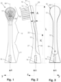
- the Figure 1 shows a schematic representation of a top view of a brush 10.
- the brush 10 comprises a truncated cone-shaped base part 11, a rod-shaped neck part 12 which adjoins the truncated cone-shaped base part 11, and finally a plate-shaped head part 13 which adjoins the neck part 12.
- the three parts form the basic body of the brush.
- the truncated cone-shaped base part 11 comprises a drive adapter.
- this is essentially formed by a channel-shaped receptacle 14 into which a pin of the handset of the sonic toothbrush can be inserted and locked (see below for Figure 4 ).
- the brush 10 has a foot part longitudinal axis 20 which is aligned coaxially to the holder 14 or, when the sonic toothbrush is in operation, coaxially to the pin.
- This longitudinal axis defines the x-axis of the xyz coordinate system used here.
- the drive adapter defines the geometric foot part longitudinal axis (x) of the brush.
- the bristle field 17 of the head part 13 is also visible, which in the present case has several (e.g. 20 - 40) tufts, each with a plurality (e.g. 100 - 200) of bristles.
- the head part 13 is teardrop-shaped when viewed from the front. This means that its shape gradually widens - starting at the transition to the neck part - almost to the upper end of the head part and ends there in a rounded final contour. With this shape (for a given length of the bristle field in the x direction) the center of gravity of the head part 13 is closer to the end of the brush. This can increase the eccentric effect at the specified operating frequency and thus also the "8" movement.
- the main surface of the plate-shaped head part 13 extends essentially transversely along the x-axis in the y-direction.
- an "8" lying in the y-direction is also shown with the reference number 23.
- the “8” illustrates the movement which is carried out in the plane due to the selected material property (modulus of elasticity), the angle between the geometric foot part longitudinal axis 20 and the geometric head part alignment axis (see below) and the bending position during operation.
- the brush In addition to the "8", the brush also performs a small nodding movement with the head part 13 - this movement is essentially perpendicular to the "8", i.e. essentially in the z-direction. In the sense of a preferred embodiment, the bristles are thus moved in three dimensions (x, y, z).
- the Figure 2 shows a schematic representation of a side view of the brush 10.
- the geometric Head part alignment axis 21 is visible.
- the foot part longitudinal axis 20 and the head part alignment axis 21 are one behind the other.
- the head part alignment axis 21 is essentially the longitudinal axis of the head part.
- the two axes intersect in the geometric bend position 22.
- the geometric foot part longitudinal axis 20 and the geometric head part alignment axis 21 enclose an angle ⁇ (gamma) of 10°.
- the geometric bend position 22 has a distance K to the end surface of the foot part 11 of 50% of the total length L of the brush 10. In this combination of the angle to the bend position 22, a brush 10 is created with which a particularly effective and gum-friendly cleaning of the teeth is possible.
- the head part 13 is plate-shaped and the neck part 12 is rod-shaped.
- the head part 13 and the neck part 12 have the same transverse dimension (i.e. the same thickness).
- the head part 13 is about three times as wide (y-direction) as the neck part 12.
- the length (x-direction) of the head part is about one third greater than the width (y-direction).
- the neck part 11 is, for example, one third as wide and 1.5 times as long as the head part 13.
- the neck part 12 is tapered compared to the head part 13 and the foot part 11.
- the neck part 12 is in at least one of the side views (here in the z-direction according to Figure 1 viewed from the side) is less wide than the headboard 13.
- the deflection is determined by the ratio of distance A to length L of the brush.
- the distance A corresponds to the distance from the front center of the head part (which here corresponds to the center of the bristle field 17) to the foot part longitudinal axis 20 (see Figure 2 ). In this example, the deflection is 14%.
- the bristles are arranged in several tufts and protrude vertically from the main surface of the plate-shaped head part. In the present case, they are perpendicular to the y-direction and run in the x-z plane. In the present embodiment, the bristles are attached to the front of the head part (or the front 27 of the brush), i.e. they point slightly downwards towards the adapter surface (y-z plane) of the foot part.
- the Figure 3 shows a schematic representation of a back view of the brush 10 according to the Figures 1 and 2
- the base body has a different material on the back 26, which is soft and offers protection (protective layer, protective coating) when the back of the brush comes into contact with the teeth.
- This material is non-load-bearing and can therefore have an E-modulus outside the E-modulus range of 2000 - 6000 MPa according to the invention.
- the load-bearing material can be seen on the front 27 and it makes up a significant part of the cross-section of the base body.
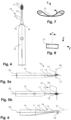
- the Figure 4 shows a schematic representation of a top view (z-direction) of a sonic toothbrush comprising the brush 10 and a handset 16 with a pin 15.
- the brush 10 is attached to the pin 15 so that the brush is detachable, rotationally fixed and axially fixed.
- the handset 16 rotates the pin 15 back and forth at a frequency of e.g. 180 - 270Hz with an amplitude of e.g. 2° (relative to a rest position) about the longitudinal axis of the pin 15 (which corresponds to the longitudinal axis of the handset 16).
- the brush therefore rotates back and forth about the foot part longitudinal axis 20 (x-axis).
- the Figure 5a shows a schematic representation of a side view of a sonic toothbrush 10.
- the sonic toothbrush 10 comprises a handset 16 and a brush 10.
- the drive of the handset 16 is designed as a piezoelectric drive (not shown), which generates an oscillation of the brush 10 about the x-axis 20 (longitudinal axis of the handset).
- the brush 10 thus carries out a rotational oscillation about the x-axis 20 relative to the handle.
- Due to the deflection of the head part 13 according to the invention an imbalance arises, which has a movement component in the Y-direction 24 and/or in the Z-direction 25 (see below, Figure 5b ).
- This effect is controlled by the suitably angled bend in the brush neck, the suitably selected modulus of elasticity and can be adjusted by further geometric design features of the brush (such as bend angle position, deflection, mass distribution and other features according to the particular embodiments of the invention).
- the Figure 5b shows a schematic plan view of a personal care device according to Figure 5a .
- the Z direction 25 is visible. It runs essentially in the direction of the bristles.
- the handset is significantly larger than the brush. This is the only way it can generate a longitudinal axis vibration (instead of an undefined or undirected vibration movement, as is the case with known sonic toothbrushes).
- the Figure 6 shows an embodiment of the sonic toothbrush, which comprises exactly one tuft 18.
- the tuft 18 is arranged at the back with respect to the head part 13.
- the head part is essentially tilted backwards.
- the Figure 7 shows a schematic representation of the "8" movement according to the invention.
- the "8" movement has the shape of a one-sided flattened “8", with a symmetry axis (X-axis) running through the center 27 of the "8".
- the two loops 28a, 28b of the "8" extend in the y-direction.
- the invention is not limited to exactly this form of the "8" movement, the exact form The movement ultimately depends on the parameters of the brush head and the vibration generated by the handset motor.
- the Figure 8 illustrates the amplitude of the longitudinal axis oscillation movement.
- the x-axis is perpendicular to the plane of the drawing.
- the plate-shaped head part 13 (shown without bristles) pivots around the x-axis at the angle ⁇ (alpha).
- the bristles extend in Figure 8 in the z-direction upwards).
- the main component of the pivoting movement (and thus the bristle wiping movement) is in the y-direction.
- the angle ⁇ (alpha) is preferably 2°.
- the Figure 9 shows a brush 10 with a plate-shaped oval head part 13.
- the longitudinal axis of the oval shape runs essentially in the x-direction and the transverse axis in the y-direction.
- the center of the head part 13 is further away from the upper end of the brush 10 than in the case of the drop-shaped head part according to Figure 1 .
- Figure 10 shows a brush with a bending angle ⁇ (gamma) of 14° and a distance K of the geometric bending position 22 to the end surface 29 of the foot part 11 of 75% based on the length L of the brush.
- the foot part 11 tapers from the end surface 29 to the transition into the neck part 12.
- the foot part 11 can be, for example, truncated cone-shaped or truncated pyramid-shaped, with a concave profile in longitudinal section, for example.
- the center of gravity of the foot part 11 is therefore closer to the end surface 29 than with a comparable foot part with straight profile lines.
- the neck part 12 takes up approximately half the length (L) of the brush. As the Figure 10 As illustrated, the neck part 12 does not necessarily have to have a constant cross-section along its entire length. It can certainly have a changing contour.
- the head part 13 is formed by the extension of the neck part 12.
- the head part 13 has essentially the same transverse dimensions (viewed in a section perpendicular to the head part alignment axis 21) as the neck part 12.
- the bristle field 17 is placed laterally on the head part 13. The bristles therefore protrude perpendicular to the head part alignment axis 21.
- Figure 11 shows an embodiment in which the foot part 11 is essentially formed by a pin 30 as a drive adapter.
- the neck part 12 is rod-shaped and takes up 90% of the length of the brush, for example.
- the head part 13 is the part in which the bristle field 17, here in the form of a single tuft, is anchored.
- the pin 30 is inserted into the handset in the x-direction for rotationally fixed coupling to a sonic toothbrush drive with longitudinal axis vibration, whereby the drive adapter defines the geometric foot part longitudinal axis (x) of the brush.
- a brush according to Fig. 11 is made of a material with an E-modulus of approx. 4600 MPa.
- the brush 10 has an interdental brush for cleaning the spaces between the teeth instead of the bristle field 17.
- a brush for a sonic toothbrush drive is created, which leads to a particularly advantageous movement of the head part for an effective cleaning of the teeth while gentle on the gums.
Landscapes
- Brushes (AREA)
Description
- Die Erfindung betrifft eine Bürste für eine Schallzahnbürste mit Längsachsenschwingung mit einem länglichen Grundkörper, der: einen kegelstumpfartigen Fussteil hat mit einen Antriebsadapter zum rotationsfesten Koppeln an einen Schallzahnbürstenantrieb mit Längsachsenschwingung; einen Kopfteil hat mit einen Borstenträger, in welchen eine Vielzahl von Borsten verankert ist; und der einen länglichen Halsteil hat, der Fussteil und Kopfteil verbindet.
- Es gibt unterschiedliche Arten von elektrisch angetriebenen Zahnbürsten.
- Aus den Druckschriften
DE 10 2016 011477 (Schiffer ),EP 2'454'967 A1 (Braun ),WO 2005 046508 A1 (Trisa ) und anderen ist das Prinzip des runden Bürstenkopfs bekannt, der um eine Achse parallel zu der Borstenrichtung rotieren kann und um diese Achse hin und her bewegt wird. Der Vorteil dieser Anordnung ist, dass der bewegte Teil (nämlich der runde Bürstenkopf) sehr klein ist. Es braucht nicht viel Antriebsenergie und auftretenden Kräfte (Drehmomente) sind tendenziell klein. Der Nachteil dieses Prinzips liegt darin, dass die Borstenbewegung abhängig ist von der Distanz zur Rotationsachse. Je näher die Borsten zur Achse des Bürstenkopfs sind, desto geringer ist die Hin- und Her-Bewegung. Das Bewegungsmuster ist also sehr inhomogen verteilt über das Borstenfeld. - Aus den Druckschriften
JP H04-43127 (Kao US 2006 168744 A1 (Butler ),US 2012/0291212 (Montagnino ) und anderen ist das Prinzip der Pendelbewegung bekannt. Dabei pendelt die Bürste um eine Pendelachse, die senkrecht zum Handapparat (Antrieb) und zur aufgesetzten Bürste steht und die die Längserstreckungsachse von Handapparat und Bürste am Ort der Kopplung der Bürste an den Handapparat schneidet. Der Vorteil ist, dass die Bewegungsintensität über das ganze Borstenfeld homogen verteilt ist. Alle Borsten haben nämlich mehr oder weniger den gleichen Abstand von der Pendelachse. Der Nachteil besteht allerdings darin, dass relativ grosse Kräfte (Momente) auftreten, weil der Bürstenkopf mit seiner Masse relativ weit von der Pendelachse entfernt ist. - Aus den Druckschriften
JP 2012-161368 (Sanion DE 299 13 406 U1 (Rowenta ),US 6,766,548 B1 (Rowenta ),WO 2005 046508 A1 (Trisa ),WO 2013/104020 A1 (Erskine ) und anderen ist das Prinzip der Gehäusevibration bekannt. Ein Antrieb im Handapparat oder im Bürstenhals erzeugt eine nicht näher definierte Vibration, die sich auf die Borsten überträgt. Der Vorteil dieser Konstruktion ist, dass man sich nicht mit den technischen Details der Bewegungsübertragung befassen muss. Der Nachteil ist aber, dass man das ganze Gehäuse vibrieren muss und dass entsprechend mehr Antriebsenergie benötigt wird, als wenn nur ein kleiner Teil in Vibration versetzt werden muss. Zudem darf die Vibration nicht zu stark sein, weil das den Komfort beim Halten des Handapparats beeinträchtigt. Schliesslich sind die effektiven Bewegungen der Borsten nicht bekannt und die Wirkung der Reinigung dieser Art von undefinierter und unkontrollierter Vibration ist alles andere als optimal. - Eine weiteres Prinzip ist aus den Druckschriften
WO 2012-151259 A1 (Water Pik ), EP 2'548'531 B1 (Trisa) und anderen bekannt. Hier hat der Handapparat einen Kopplungsstift, der sich um die Längsachse hin und her dreht. Die auf den Kopplungsstift aufgesetzte Bürste hat einen geraden Hals und am Ende eine Borstenplatte, von der die Borsten quer zur Längsachse des Handapparats bzw. des Bürstenhalses stehen. Der Vorteil dieser Geometrie besteht darin, dass relativ geringe Kräfte (Momente) auftreten, weil die Masse (Hals, Borstenplatte) der Aufsatzbürste relativ nahe bei der Längsachse (Bewegungszentrum) ist. Auch ist die Bewegungsintensität relativ gleichmässig über das Borstenfeld verteilt. Der Nachteil dieses Prinzips ist jedoch, dass die Borsten nur eine eindimensionale Bewegung (hin und her) ausführen. Zum einen ist dadurch der Aufschäumeffekt für die Zahnpasta unbefriedigend und zum anderen fehlt der Vorteil der kreisenden und damit schonenden und gleichzeitig effizienten Bewegung, die von den Spezialisten im Zusammenhang mit der Handzahnbürste seit Jahrzehnten als vorteilhaft gelehrt wird. - Bei Handzahnbürsten ist bekannt, dass der Reinigungseffekt von der Härte der Borsten abhängt. Borsten unterschiedlicher Härte haben je nach Einsatzzweck unterschiedliche Reinigungswirkung und unterschiedliches Schädigungspotenzial. Diese Effekte sind in Fachkreisen bekannt und fliessen regelmässig auch in die Beratung der Patienten ein.
- Die Schallzahnbürsten sind für den Benutzer sehr bequem und gelten auch als effizient, weil die elektrisch angetriebene Bürste die Bewegungen sehr viel schneller macht, als man es von Hand tun kann.
- Bei den Schallzahnbürsten hat man sich bisher darauf gestützt, dass die Reinigung umso besser ist, je höher die Frequenz des Motors ist und je grösser die Reinigungsbewegung der Borsten ist.
- Aus der
WO 2017/050612 A1 (Curaden ) ist eine Schallzahnbürste bekannt, die einen abgewinkelten Bürstenkopf hat. Dadurch dass die Schallzahnbürste nach vorn gewinkelt ist, sind die verschiedenen Stellen des Gebisses besser zugänglich. Zudem wird mit dem Knick erreicht, dass die Filamente der Bürsten mit grösserer Amplitude quer zur Bürstenlängsachse schwingen. Die bevorzugte Betriebsfrequenz ist bei 2000 bis 8000 Hertz. Die Frequenzen können aber auch höher zum Beispiel bei 10 kHz, 50kHz oder auch tiefer, zum Beispiel bei 200 Hz oder 500 Hz liegen. - Aus der
US 2012/0291212 A1 ist eine Ultraschall-Zahnbürste bekannt, die zur Erhöhung der Resonanzfrequenz zwei parallele, quer zur Längsachse der Bürste verlaufende Kanäle hat. Die Frequenz wird in Vorwärts-Rückwärtsrichtung erhöht, wenn die beiden Kanäle an der Vorderseite platziert sind. Sind die Kanäle links und rechts am Bürstenhals vorgesehen, erhöht sich die Frequenz in seitlicher Richtung. - Es fehlt nach wie vor an einem ausreichenden Verständnis des Reinigungsverhaltens von Schallzahnbürsten. Die Erkenntnisse, die man heute in Bezug auf die Reinigungswirkung von Handzahnbürsten hat, lassen sich nicht auf die hochdynamische Situation einer Schallzahnbürste übertragen.
- Aufgabe der Erfindung ist es, eine dem eingangs genannten technischen Gebiet zugehörende Zahnbürste für Schallzahnbürsten zu schaffen, welche eine bessere, insbesondere für das Zahnfleisch schonende Reinigungswirkung hat. Insbesondere soll eine definierte und kontrollierte zweidimensionale Bewegung der Borsten erzeugt werden.
- Die Lösung wird durch den Anspruch 1 definiert. Der Grundkörper hat dahingehend einen Knick-Winkel, dass eine geometrische Fussteil-Längsachse und eine geometrische Kopfteil-Ausrichtungsachse einen Winkel γ im Bereich von 5° bis 12° einschliessen. Zudem hat eine geometrische Knickposition im Grundkörper einen Abstand zu einer Endfläche des Fussteils von mindestens 60% einer Gesamtlänge des Grundkörpers.
- Die Schallzahnbürste gemäss der Erfindung erzeugt grundsätzlich eine Schwingung der Bürste um die Längsachse, also die Fussteil-Längsachse (die hier als x-Achse definiert wird). Die Borsten führen dadurch primär eine Wischbewegung quer zur genannten Längsachse aus. Ein besonderer Vorteil der erfindungsgemässen Bürste liegt darin, dass sie eine Knickwinkel-Position hat, die eine genügend grosse Auslenkung (auch Exzentrizität genannt) des Kopfteils zur Folge hat, so dass auch eine bestimmte Schwingung in Richtung der Längsachse ausführt. Es resultiert eine zweidimensionale Bewegung, die als "8-er" Bewegung bezeichnet werden kann. Eine solche ist in mehrerer Hinsicht besonders vorteilhaft.
- Die Kombination aus dem speziellen Knickwinkel, der gemäss der Erfindung nicht zu klein und nicht zu gross ist, und aus der erfindungsgemässen Knickwinkelposition, die nicht allzu nahe beim Fussteil ist, ergibt sich eine Auslenkung (bzw. Exzentrizität bezüglich der Fussteil-Längsachse) und eine Hebelwirkung, die beim Betrieb der Zahnbürste zu einer leicht nickenden Bewegung des Bürstenkopfs führt. Das ergibt die oben genannte zweidimensionale "8"-Bewegung der Borstenspitzen.
- Es ist allerdings ein Vorteil der vorliegenden Bürstenkonstruktion, dass die Bürste auch eine kleine "Nickbewegung" in Richtung der Borsten durchführt. Dadurch wird die Mischung aus Speichel und Zahnpasta "vorwärts" in die Zahnzwischenräume getrieben. Dies ist insbesondere bei Einbüschel-Zahnbürsten von Bedeutung, die speziell für eine bessere Interdentalreinigung geeignet sind.
- Die Erfindung geht im Übrigen von folgenden Grundmerkmalen aus:
- a) Die Bürste hat einen Fussteil, an welchem ein Adapter zum Handapparat, ein sogenannter Antriebsadapter ausgebildet ist. Der Adapter ist in geometrischer Hinsicht darauf ausgelegt, mit einem Kopplungsteil (z.B. Stift) des Schallzahnbürstenantriebs drehfest (aber auswechselbar) verbunden zu werden. Der Schallzahnbürstenantrieb erzeugt eine Längsachsenschwingung, die auf die Bürste zu übertragen ist. Der Antriebsadapter definiert eine geometrische Fussteil-Längsachse (x) der Bürste. Diese Längsachse ist im Normalfall die Richtung, in welcher man die Bürste auf den Handapparat aufstecken kann.
- b) Weiter hat die Bürste einen Kopfteil mit einen Borstenträger, in welchen eine Vielzahl von Borsten verankert ist (Borstenfeld). Der Kopfteil ist im Prinzip das obere Ende der Bürste (wohingegen der Fussteil das untere Ende bildet). Der Kopfteil definiert eine Kopfteil-Ausrichtungsachse. Die im Kopf verankerten Borsten ragen z.B. quer zur Kopfteil-Ausrichtungsachse weg. Typischerweise, aber nicht zwingend, stehen die Borsten senkrecht zur Kopfteil-Ausrichtungsachse.
- c) Zwischen Fussteil und Kopfteil hat der Grundkörper einen Halsteil. Der Halsteil verbindet also Fussteil und Kopfteil miteinander. Er ist im Vergleich zum Fussteil querschnittsverjüngt. Das heisst, wenn man den Fussteil im Querschnitt (bezogen auf die Fussteil-Längsachse) betrachtet, dann sind die Abmessungen in x- oder y-Richtung kleiner als beim Querschnitt des Halsteils (also quer zur Halsteil-Längsachse). Dabei ist querschnittsverjüngt auf die Querschnittsfläche zu beziehen. Es ist also nicht zwingend, dass die Abmessungen in x-Richtung und y-Richtung geringer sind.
- In einer ersten Variante weist der Borstenträger eine mehrere Büschel mit jeweils einer Vielzahl an Borsten auf. In einer zweiten Variante weist der Borstenträger genau einen Büschel mit einer Vielzahl an Borsten auf (Einbüschel-Variante).
- Die Borsten können allerdings auch indirekt mit der Oberfläche des Borstenträger verankert sein, insbesondere wenn die Bürste als Interdentalbürste ausgebildet ist. In einer dritten Variante weist der Borstenträger an dessen Oberfläche eine verwundene oder geschlagene Drahtschlaufe auf, wobei zwischen den Litzen die Borsten festgeklemmt sind. In diesem Fall ist die Kopfteil-Ausrichtungsachse vorzugsweise rechtwinklig zur Drahtausrichtung ausgerichtet.
- Die geometrische Knickposition wird durch einen Schnittpunkt zwischen der geometrischen Fussteil-Längsachse und der geometrischen Kopfteil-Ausrichtungsachse definiert. An der geometrischen Knickposition muss also nicht zwingend ein knickartige (oder knieartige) Richtungsänderung des Grundkörpers vorhanden sein. Vorzugsweise befindet sich die geometrische Knickposition innerhalb des Grundkörpers. Die Form des Grundkörpers muss nicht zwingend einen optisch erkennbaren Knick umfassen, sondern kann zum Beispiel bogenförmig ausgebildet sein. In Varianten kann weiter die geometrische Knickposition auch ausserhalb des Grundkörpers liegen. Dem Fachmann sind weitere Variationen bekannt.
- Der Abstand zwischen der Endfläche des Fussteils und der Knickposition wird entlang der Fussteil-Längsachse gemessen. Ebenso wird die Gesamtlänge des Grundkörpers entlang der Fussteil-Längsachse gemessen.
- Die geometrische Knickposition weist erfindungsgemäss einen relativ grossen Abstand vom Kopfteil auf um im Zusammenhang mit dem Winkel γ (gamma) zwischen der geometrischen Fussteil-Längsachse und der geometrischen Kopfteil-Ausrichtungsachse von 5° bis 12° einen besonders optimales Schwingungsverhalten zur Reinigung der Zähne zu erreichen. Je grösser der Winkel gewählt wird, desto stärker wird die Auslenkung des Kopfteils von der Fussteil-Längsachse (Exzentrizität). Ebenso wird die Exzentrizität grösser, wenn die Knickposition weiter von dem Kopfteil entfernt wird. Es hat sich aber gezeigt, dass die beiden Parameter (Knickposition und Winkel) das Schwingungsverhalten nicht in demselben Masse und in derselben Art und Weise beeinflussen, so dass hinsichtlich der Reinigungswirkung z.B. ein vergrössern des Winkels nicht direkt durch einen kleineren Abstand zwischen der Knickposition und dem Kopfteil kompensiert werden kann, da das 2-dimensionale respektive 3-dimensionale Schwingungsbild des Kopfteils auf die beiden Parameter unterschiedlich reagiert.
- Der Abstand der geometrischen Knickposition zu der Endfläche des Fussteils beträgt gemäss der Erfindung mindestens 60% der Gesamtlänge des Grundkörpers. Damit wird ein besonders optimaler Bereich für die geometrische Knickposition definiert, welcher gemäss den Experimenten zu besonders vorteilhaften 2-dimensionalen respektive 3-dimensionalen Schwingungsbildern führt. Damit kann eine besonders effektive und gleichzeitig schonende Zahnreinigung erreicht werden.
- Gemäss einer besonderen Ausführungsart beträgt der Abstand der geometrischen Knickposition zu der Endfläche des Fussteils höchstens 75% der Gesamtlänge (L) des Grund¬körpers. In diesem nach oben begrenzten Bereich lässt sich mit dem erfindungsgemässen Knickwinkel von 5° bis 12° mit grossen Gestaltungsfreiraum bezüglich der geometrischen Abmessungen von Halsteil und Kopfteil eine genügend starke "8"-Bewegung erreichen.
- Gemäss der Erfindung ist der Kopfteil plattenförmig und der Halsteil stangenförmig. Der Kopfteil ist also im Querschnitt (also in der Ebene senkrecht zur die Kopfteil-Ausrichtungsachse) in der einen Richtung (z.B. y-Richtung) breiter als in der anderen Richtung (z.B. z-Richtung). Die Form des Querschnitts kann beispielsweise rechteckig, trapezförmig oder oval sein.
- Der Halsteil ist z.B. im Querschnitt kreisrund, oval, viereckig, sechseckig, achteckig, trapezförmig oder eine geometrische Annäherung oder Abwandlung einer solchen Form. Die Querschnittsform muss nicht drehsymmetrisch sein.
- Gemäss einer ersten besonderen Ausführungsform ist der Kopfteil mindestens etwa doppelt so breit wie der Halsteil.
- Entsprechend einer zweiten besonderen Ausführungsform ist der Kopfteil höchstens etwa 1,5 mal so lang wie der Halsteil. Dies lässt sich auch kombinieren mit der zuvor genannten Ausführungsform.
- Gemäss einer dritten besonderen Ausführungsform ist der Kopfteil in einem Querschnitt aufgespannt durch die Längsachse der Bürste und die Kopfausrichtungsachse etwa gleich dick wie der Halsteil. Ist der Kopfteil plattenförmig, dann ist also der Halsteil etwa gleich dick wie die Kopfteilplatte.
- Bei einer Ausführungsform ist der Kopfteil mindestens etwa doppelt so breit und höchstens etwa 1,5 mal so lang wie der Halsteil. Besonders bevorzugt ist der Kopfteil zwischen 2 und 3 Mal so breit und vorzugsweise zwischen 0.5 und 1.5 Mal so lang wie der Halsteil. Mit dem im Vergleich zum Kopfteil relativ schlanken Halsteil wird ein besonders gutes Schwingungsverhalten erreicht und damit eine optimale Reinigung der Zähne erreicht.
- In Varianten kann der Kopfteil auch weniger als doppelt so breit und mehr als 1.5 Mal so lang wie der Halsteil sein.
- Bei einer besonderen Ausführungsart hat der Kopfteil eine Masse, die grösser als eine Masse des Halsteils ist, insbesondere hat der Kopfteil eine Masse, die vorzugsweise mehr als 30%, besonders bevorzugt mehr als 50% grösser ist als die Masse des Halsteils. Diese Massenverteilung lässt sich entweder durch entsprechende geometrische Abmessungen oder durch unterschiedliche Materialien oder durch beides erreichen.
- Die relativ grosse Masse des Kopfteils im Vergleich zum Halsteil hat den Effekt, dass beim Betrieb der Zahnbürste eine leicht nickende Bewegung des Bürstenkopfs (eine Bewegung in z-Richtung) optimiert werden kann. Durch die grössere Masse kann der Impuls der Nickbewegung vergrössert werden, womit die zweidimensionale "8"-Bewegung verstärkt werden kann und womit wiederum die Zahnzwischenräume besser erreicht werden können. Dies ist insbesondere, aber nicht nur, bei der Einbüschelvariante respektive bei der Interdentalbürste von grossem Vorteil.
- In Varianten kann der Kopfteil auch eine Masse aufweisen, welche weniger als 30% grösser ist, als die Masse des Halsteils, insbesondere können die Massen des Kopfteils und des Halsteils auch ungefähr gleich sein. Dies z.B. wenn der Kopfteil gleich dick wie der Halsteil ist, und wenn der Halsteil dreimal so lang wie der Kopfteil ist und der Kopfteil dreimal so breit wee der Halsteil ist.
- Vorzugsweise ist der Fussteil etwa gleich lang wie der Kopfteil. Damit ist der Fussteil ausreichend gross, um eine stabile Befestigung am Schallzahnbürstenantrieb zu erreichen (z.B. mit einem langen Adapterkanal für einen entsprechend langen Stift des Handapparats). Die Schwingung und damit die kinetische Energie des Antriebs wird effizient über das Halsteil an den Kopfteil übertragen werden.
- Bei einer besonderen Ausführungsart ist der Fussteil kürzer als der Kopfteil, insbesondere ist der Fussteil etwa halb so lang wie der Kopfteil. Dadurch wird mehr Gestaltungsfreiraum für den Halsteil geschaffen. Wenn bei einer solchen Ausführungsart zudem der Antriebsadapter als schlanker Stift an der Bürste ausgebildet ist, der in einen Adapter-Kanal im Handapparat eingeführt wird, dann ist die stabile Befestigung am Schallzahnbürstenantrieb versteckt.
- In Varianten kann der Fussteil auch länger als der Kopfteil sein.
- Vorzugsweise hat der Halsteil eine Querabmessung, die nicht mehr als ein Viertel einer Länge des Halsteils ist. Unter der Querabmessung ist ein Durchmesser rechtwinklig zur geometrischen Ausrichtungsachse bzw. rechtwinklig zur Fussteil-Längsachse zu verstehen. Dort wo der Halsteil an den Kopfteil anschliesst, ist die Kopfteil-Ausrichtungsachse massgeblich und dort, wo der Halsteil an den Fussteil anschliesst, ist die Fussteil-Längsachse massgeblich. Der Halsteil wird damit bewusst schlank gehalten, so dass damit das Schwingungsverhalten des Kopfteils unterstützt werden kann, insbesondere das Schwingungsverhalten in der Ebene (die "8"-Bewegung) und die Nickbewegung.
- In Varianten kann die Querabmessung auch mehr als ein Viertel einer Länge des Halsteils betragen. Dies kann dann sinnvoll sein, wenn zum Beispiel ein besonders flexibles respektive elastisches Material für den Halsteil verwendet wird.
- Bevorzugt hat der Grundkörper ein tragendes Material mit einen E-Modul von weniger als 8'000 MPa. Insbesondere liegt der E-Modul in einem Bereich von 2000 MPa bis 6000 MPa. Damit wird ein Grundkörper erhalten, welcher hinreichend elastisch ist, um die Schwingungen optimal zu übertragen und anderseits ebenfalls hinreichend stabil ist.
- Bevorzugt beträgt der E-Modul mindestens 2500 MPa, insbesondere mindestens 3000 MPa. Damit wird ein Grundkörper sichergestellt, welcher hinreichend fest ist, um die Längsachsen-Schwingungen optimal zu übertragen.
- In gewissen Varianten der Erfindung (z.B. bei eher kleinen Knickwinkeln im Bereich von 8°) kann der E-Modul tendenziell niedriger sein (z.B. 2000 MPa bis 3000 MPa) als bei grossen Knickwinkeln (z.B. bei 15°).
- Eine weitere besondere Ausführungsart zeichnet sich dadurch aus, dass der E-Modul des tragenden Materials (bzw. der tragenden Materialien) des Grundkörpers im Bereich von 4000 MPa bis 6000 MPa liegt.
- Ist die Masse des Kopfteils relativ gross im Verhältnis zum Querschnitt des Halsteils, dann ist ein E-Modul im Bereich von 5000 MPa bis 6000 MPa von Vorteil.
- Vorzugsweise besteht der Grundköper im Wesentlichen einteilig aus einem Material. Damit wird einerseits eine besonders kostengünstige Herstellung des Grundkörpers erreicht. Anderseits wird damit auch ein besonders optimales Schwingungsverhalten ermöglicht, da keine Grenzübergange von unterschiedlichen Materialien das Schwingungsverhalten stören, insbesondere ein 2-dimenionales respektive 3-dimensionales Schwingungsverhalten, bei welchem ein solcher Grenzübergang durch das Schwingungsbild in unterschiedlichen Richtungen gebogen wird.
- Im Rahmen der Erfindung wird auch dann von einem einteiligen Grundkörper aus einem tragenden Material gesprochen, wenn die Oberfläche der Bürste durch ein nichttragendes Material beschichtet oder ummantelt ist. Zum Beispiel, können bei einem einteiligen Grundkörper an dem Fussteil Bereiche aus einem Material mit erhöhter Rauhigkeit oder Oberflächengriffigkeit vorgesehen sind, so dass die Bürste besser mit den Fingern vom Antriebsstift entfernt werden kann.
- Gemäss einer besonderen Ausführungsform ist der Grundköper im Wesentlichen durch zwei stoffschlüssig verbundenen Materialteile gebildet. Wird beispielsweise der Fussteil aus einem anderen Kunststoff gespritzt als der Hals und der Kopf der Bürste, dann kann mit einem sehr steifen Kunststoff (mit einem hohen E-Modul) sichergestellt werden, dass die Kopplung zum Antriebsstift am Handapparat die Bewegung des Antriebs optimal auf die Bürste überträgt. Gleichwohl kann der Hals genügend elastisch gestaltet werden mit einem weniger steifen Material (E-Modul des Materials des Halsteils ist niedriger als E-Modul des Fussteils).
- Eine weitere besondere Ausführungsart zeichnet sich dadurch aus, dass der Grundköper im Wesentlichen durch drei stoffschlüssig verbundene Materialteile gebildet ist. So kann der Grundkörper z.B. in Längsrichtung aus zwei stoffschlüssig verbundenen Materialteilen unterschiedlicher Festigkeit bestehen. Weiter ist es denkbar, dass Kopfteil, Halsteil und Fussteil je aus unterschiedlichen Materialien gebildet sind. Die Anforderungen an den Kopfteil sind anders als die an den Fussteil, was mit der Materialwahl optimiert werden kann.
- Ein Grundkörper aus zwei oder drei stoffschlüssig verbundenen Materialien ergibt sich z.B. durch moderne Kunststoff-Spritzgussverfahren mit zwei oder drei Materialien.
- Auch am Grundkörper mit den zwei oder drei tragenden Materialteilen können noch nicht-tragende (z.B. weiche) Mantelschichten vorhanden sind, um bestimmte Funktionen (z.B. Schutz beim Kontakt der Bürstenrückseite mit den Zähnen) zu erreichen.
- Vorzugsweise hat der Kopfteil eine Auslenkung von 10% - 20% bezogen auf eine Länge der Bürste. Unter der Auslenkung wird vorliegend ein Verhältnis zwischen der Distanz eines Zentrums (Schwerpunkt) des Kopfteils zur Adapter-Längsachse, geteilt durch die Gesamtlänge L (in x-Richtung) des Grundkörpers verstanden. Die Auslenkung kann man als "Exzentrizität des Kopfteils bezüglich der Adapterlängsachse" betrachten. Die Auslenkung ist beim Schwingungsbild massgebend: so wurde festgestellt, dass mit der Auslenkung von 10% - 20% die "8" Bewegung besonders ausgeprägt ausgeführt wird.
- Die Auslenkung kann auch kleiner als 10% oder grösser als 20% sein kann. Bei Bürsten, die insgesamt eine geringe Länge haben, wird die Auslenkung vorzugsweise im Bereich von 20% gewählt, damit die "Unwucht" des Kopfes nicht zu klein wird. Bei Bürsten, die für hohe Betriebsfrequenzen (z.B. über 240 Hz) bestimmt sind, wird die Auslenkung eher im Bereich von 10% gewählt, weil bei höheren Frequenzen die "Unwucht" des Kopfes ansonsten zu gross werden könnte.
- Gemäss der Erfindung ragen die Borsten im Wesentlichen senkrecht von der Kopfteil-Ausrichtungsachse der Bürste weg. Der Winkel zwischen der Fussteil-Längsachse und der Borstenrichtung beträgt dann 90° minus Knickwinkel γ (gamma). Bei einem Knickwinkel von beispielsweise γ = 9° ergibt sich 90° - 9° = 81°.
- Die Borsten sind z.B. auf der Hauptfläche des plattenförmig ausgebildeten Kopfteils verankert. Der Kopfteil kann bei einer Einbüschelbürste aber auch stangenförmig sein, wobei das einzige Büschel in einer zylindrischen Ausnehmung (z.B. einem Sackloch) verankert ist.
- Bevorzugt schliessen eine geometrische Fussteil-Längsachse und eine geometrische Kopfteil-Ausrichtungsachse einen Winkel γ (gamma) im Bereich von 7° bis 10° ein. Dieser Winkelbereich hat sich bei Experimenten als besonders vorteilhaft erwiesen, so dass damit für die Zahnreinigung ein besonders ideales Schwingungsbild erreicht werden kann. Experimente haben gezeigt, dass damit das Schwingungsbild, insbesondere die "8" Bewegung besonders vorteilhaft ausgeprägt ist, womit die Zahnreinigung mit der Bürste besonders schonend durchgeführt werden kann. Der Winkelbereich hat sich weiter im Zusammenhang mit der Auslenkung bzw. Exzentrizität des Kopfteils bezogen auf die Gesamtlänge der Bürste zwischen 10% und 20% als besonders vorteilhaft erwiesen und ebenfalls zu besonders guten Reinigungsergebnissen bei optimaler Ergonomie geführt.
- Der Winkelbereich von 7° - 10° in Kombination mit einer Auslenkung von 10% bis 20% führt zu einer guten Eigendynamik der Schwingung des Bürstenkopfs im Sinn der gewünschten "8- Bewegung".
- Bei einer besonderen Ausführungsart ist der Halsteil im Vergleich zum Kopfteil querschnittsverjüngt. Das heisst, dass der Kopfteil breiter und/oder dicker ist (senkrecht zur Kopfteil-Ausrichtungsachse betrachtet) als der Halsteil. Damit wird der Halsteil mechanisch weniger steif als der Kopfteil (sofern der Grundkörper aus einem oder mehreren Materialien mit ungefähr gleichem E-Modul gefertigt ist).
- Eine erfindungsgemässe Schallzahnbürste mit Längsachsenschwingung umfasst eine erfindungsgemässe Bürste und einen Handapparat mit einer Bürstenkupplung zum lösbaren befestigen der Bürste am Handapparat und mit einem Antrieb, der an der Bürstenkupplung eine Längsachsenschwingung erzeugt. Der Antrieb kann zum Beispiel einen Piezoantrieb, einen Magnetantrieb und/oder einen elektro-Drehantrieb aufweisen. Besonders bevorzugt wird ein Piezoantrieb eingesetzt, insbesondere aufgrund des einfachen Aufbaus, der besonders kompakten Bauweise und der präzisen Steuerbarkeit.
- Vorzugsweise ist der Antrieb ausgebildet, um eine Längsachsenschwingungs-Frequenz im Bereich von 150 Hz bis 400 Hz zu erzeugen. Da mit der Bürste ein 2-dimensionales respektive 3-dimensionales Bewegungsbild erzeugt wird, ist die Längsachsenschwingungs-Frequenz relativ tief angesetzt, so dass mehr Zeit für die Durchführung mehrerer Richtungsänderungen pro Schwingung, z.B. bei einer "8"-Bewegung" zur Verfügung steht. Die Längsachsenschwingungs-Frequenz ist mit Vorteil nicht höher als 300 Hz. Ist die Frequenz zu hoch, kann der Grundkörper die vom Antrieb erzeugte Längsachsenschwingung nicht mehr zum Bürstenkopf übertragen. Es kann zu internen Torsionsbewegungen kommen die dazu führen, dass der Kopf z.B. nur noch jede zweite Schwingung ausführt.
- Die Längsachsenschwingungs-Frequenz kann auch kleiner als 150 Hz sein, z.B. 120 Hz.
- Bevorzugt ist der Antrieb ausgebildet, um eine Längsachsenschwingung mit einer Amplitude (Auslenkung bezogen auf eine Ruhestellung) von weniger als 3°, insbesondere im Bereich von 1° bis 3° zu erzeugen. Das heisst, der Fussteil wird periodisch um den Winkel um die Fussteil-Längsachse rotiert (hin und her bewegt). In Varianten kann die Amplitude auch grösser als 3° sein.
- Aus der nachfolgenden Detailbeschreibung und der Gesamtheit der Patentansprüche ergeben sich weitere vorteilhafte Ausführungsformen und Merkmalskombinationen der Erfindung.
- Die zur Erläuterung des Ausführungsbeispiels verwendeten Zeichnungen zeigen:
- Fig. 1
- eine schematische Darstellung einer Draufsicht auf eine Bürste;
- Fig. 2
- eine schematische Darstellung einer Seitenansicht der Bürste;
- Fig. 3
- eine schematische Darstellung einer Rückenansicht der Bürste;
- Fig. 4
- eine schematische Darstellung einer Draufsicht auf eine Schallzahnbürste umfassend die Bürste;
- Fig. 5a, b
- eine schematische Seitenansicht und einer Draufsicht einer Schallzahnbürste;
- Fig. 6
- eine schematische Darstellung einer Seitenansicht einer Schallzahnbürste mit genau einem Büschel;
- Fig. 7
- eine schematische Darstellung der erfindungsgemässen "8"-Bewegung;
- Fig. 8
- eine schematische Darstellung der Winkelamplitude der LängsachsenSchwingung;
- Fig. 9
- eine Ausführungsform mit einem ovalen Bürstenkopf;
- Fig. 10
- eine Ausführungsform einer Einbüschelbürste mit rückseitigem Borstenfeld;
- Fig. 11
- eine Ausführungsform einer Einbüschelbürste mit vorderseitigem Borstenfeld.
- Grundsätzlich sind in den Figuren gleiche Teile mit gleichen Bezugszeichen versehen.
- Die
Figur 1 zeigt eine schematische Darstellung einer Draufsicht auf eine Bürste 10. Die Bürste 10 umfasst einen kegelstumpfförmigen Fussteil 11, einen stangenförmigen Halsteil 12, der sich dem kegelstumpfförmigen Fussteil 11 anschliesst, und schliesslich einen plattenförmigen Kopfteil 13, welcher sich an den Halsteil 12 anschliesst. Die drei Teile bilden den Grundkörper der Bürste. - Der kegelstumpfförmige Fussteil 11 umfasst einen Antriebsadapter. Dieser ist vorliegend im Wesentlichen durch eine kanalförmige Aufnahme 14 gebildet, in welche ein Stift des Handapparates der Schallzahnbürste einführbar und verrastbar ist (siehe unten zu
Figur 4 ). Die Bürste 10 weist eine Fussteil-Längsachse 20 auf, welche koaxial zur Aufnahme 14 respektive im Betrieb der Schallzahnbürste koaxial zum Stift ausgerichtet ist. Diese Längsachse definiert die x-Achse des vorliegend benutzten x-y-z-Koordinatensystems.Mit anderen Worten: Der Antriebsadapter definiert die geometrische Fussteil-Längsachse (x) der Bürste. - In der
Figur 1 ist weiter das Borstenfeld 17 des Kopfteils 13 ersichtlich, welches vorliegend mehrere (z.B. 20 - 40) Büschel mit jeweils einer Vielzahl (z.B. 100 - 200) an Borsten aufweist. - Gemäss einer bevorzugten Ausführungsform ist der Kopfteil 13 in der Frontansicht tropfenförmig. Das heisst, seine Form erweitert sich - beginnend beim Übergang zum Halsteil - sukzessive bis fast zum oberen Ende des Kopfteils und endet dort in einer rundlichen Endkontur. Bei dieser Form ist (bei gegebener Länge des Borstenfeldes in x-Richtung) der Schwerpunkt des Kopfteils 13 näher beim Ende der Bürste. Dies kann den exzentrischen Effekt bei der vorgegebenen Betriebsfrequenz und damit auch die "8"-Bewegung verstärken.
- Die Hauptfläche des plattenförmigen Kopfteils 13 erstreckt sich im Wesentlichen quer x-Achse in y-Richtung.
- Auf dem Borstenfeld 17 ist weiter mit dem Bezugszeichen 23 eine in y-Richtung liegende "8" dargestellt. Die "8" illustriert die Bewegung, welche aufgrund der gewählten Materialeigenschaft (E-Modul), des Winkels zwischen der geometrischen Fussteil-Längsachse 20 und der geometrischen Kopfteil-Ausrichtungsachse (siehe weiter unten) und der Knickposition im Betrieb in der Ebene ausgeführt wird.
- Zusätzlich zu der "8" führt die Bürste auch noch eine kleine Nickbewegung mit dem Kopfteil 13 aus - diese Bewegung ist im Wesentlichen rechtwinklig zur "8" gerichtet, also im Wesentlichen in z-Richtung. Im Sinn einer bevorzugten Ausführungsform werden die Borsten somit in drei Dimensionen (x, y, z) bewegt.
- Die
Figur 2 zeigt eine schematische Darstellung einer Seitenansicht der Bürste 10. In dieser Figur ist neben der geometrischen Fussteil-Längsachse 20 auch die geometrische Kopfteil-Ausrichtungsachse 21 ersichtlich. In der Darstellung gemässFigur 1 sind die Fussteil-Längsachse 20 und die Kopfteil-Ausrichtungsachse 21 hintereinander. Die Kopfteil-Ausrichtungsachse 21 ist im Wesentlichen die Längsachse des Kopfteils. Die beiden Achsen schneiden sich in der geometrischen Knickposition 22. In der vorliegenden Ausführungsform schliessen die geometrische Fussteil-Längsachse 20 und die geometrische Kopfteil-Ausrichtungsachse 21 einen Winkel γ (gamma) von 10° ein. Die geometrische Knickposition 22 weist vorliegend einen Abstand K zu der Endfläche des Fussteils 11 von 50% der Gesamtlänge L der Bürste 10 auf. In dieser Kombination des Winkels zur Knickposition 22 wird eine Bürste 10 geschaffen, mit welcher eine besonders effektive und zahnfleisch-schonende Reinigung der Zähne möglich ist. - Wie aus der Kombination der
Figuren 1 und 2 ersichtlich ist, ist in der vorliegenden Ausführungsform der Kopfteil 13 plattenförmig und der Halsteil 12 stangenförmig. In der Projektion des Grundkörpers auf die x-z-Ebene haben der Kopfteil 13 und der Halsteil 12 die gleiche Querabmessung (also die gleiche Dicke). In der Projektion auf die x-y-Ebene (Frontansicht gemässFigur 1 ) ist der Kopfteil 13 rund dreimal so breit (y-Richtung) wie der Halsteil 12. Die Länge (x-Richtung) des Kopfteils ist etwa ein Drittel grösser als die Breite (y-Richtung). Der Halsteil 11 ist z.B. ein Drittel so breit und 1,5 mal so lang wie der Kopfteil 13. - Der Halsteil 12 ist gegenüber dem Kopfteil 13 und dem Fussteil 11 verjüngt. Im vorliegenden Beispiel ist der Halsteil 12 in zumindest einer der Seitenansichten (hier in z-Richtung gemäss
Figur 1 betrachtet) weniger breit als der Kopfteil 13. - Der Grundkörper der Bürste 10 hat im vorliegenden Beispiel als tragendes Material ein glasfaserverstärktes Polypropylen Borealis GB311U mit einem E-Modul von rund 3500 MPA (Tensile Strength at yield = 97 MPa; Elongation at Yield = 2.8%; E-Modul = Tensile Strength at Yield / Elongation at Yield).
- Die Auslenkung ist durch das Verhältnis von Abstand A zu Länge L der Bürste bestimmt. Der Abstand A entspricht dem Abstand des frontseitigen Zentrums des Kopfteils (was hier dem Zentrum des Borstenfeldes 17 entspricht) zur Fussteil-Längsachse 20 (siehe
Figur 2 ). Im vorliegenden Beispiel beträgt die Auslenkung 14%. - Die Borsten sind hier in mehreren Büscheln angeordnet und ragen senkrecht von der Hauptfläche des plattenförmigen Kopfteils weg. Im vorliegenden Fall stehen sie senkrecht zur y-Richtung und verlaufen in der x-z-Ebene. Bei der vorliegenden Ausführungsform sind die Borsten an der Vorderseite des Kopfteils (bzw. der Vorderseite 27 der Bürste) angebracht, das heisst, sie zeigen leicht nach unten zur Adapterfläche (y-z Ebene) des Fussteils.
- Die
Figur 3 zeigt eine schematische Darstellung einer Rückenansicht der Bürste 10 gemäss denFiguren 1 und 2 . Wie aus den Figuren erkennbar ist, hat der Grundkörper auf der Rückseite 26 ein anderes Material, welches weich ist und einen Schutz (Schutzschicht, Schutzmantel) beim Kontakt der Bürstenrückseite mit den Zähnen bietet. Dieses Material ist nicht-tragend und kann daher einen E-Modul ausserhalb des erfindungsgemässen E-Modul-Bereichs von 2000 - 6000 MPa haben. Das tragende Material ist auf der Vorderseite 27 ersichtlich und es macht einen wesentlichen Teil des Querschnitts des Grundkörpers aus. - Die
Figur 4 zeigt eine schematische Darstellung einer Draufsicht (z-Richtung) auf eine Schallzahnbürste umfassend die Bürste 10 und einen Handapparat 16 mit einem Stift 15. Die Bürste 10 ist auf den Stift 15 aufgesteckt, so dass die Bürste lösbar, rotationsfest und axial fixiert ist. Der Handapparat 16 dreht den Stift 15 hin und her mit einer Frequenz von z.B. 180 - 270Hz mit einer Amplitude von z.B. 2° (bezogen auf eine Ruhelage) um die Längsachse des Stifts 15 (welche der Längsachse des Handapparats 16 entspricht). Die Bürste dreht sich also hin und her um die Fussteil-Längsachse 20 (x-Achse). - Die
Figur 5a zeigt eine schematische Darstellung einer Seitenansicht einer Schallzahnbürste 10. Die Schallzahnbürste 10 umfasst einen Handapparat 16 und eine Bürste 10. Der Antrieb des Handapparats 16 ist als piezoelektrischer Antrieb (nicht dargestellt) ausgebildet, welcher eine Schwingung der Bürste 10 um die x-Achse 20 (Längsachse des Handapparats) erzeugt. Damit führt die Bürste 10 im Betrieb relativ zum Handgriff eine Rotationsschwingung um die x-Achse 20 aus. Aufgrund der erfindungsgemässen Auslenkung des Kopfteils 13 entsteht eine Unwucht, die eine Bewegungskomponente in der Y-Richtung 24 und/oder in die Z-Richtung 25 (siehe unten,Figur 5b ) unterstützt. Dieser Effekt wird durch den geeignet gewinkelten Knick im Bürstenhals, den geeignet gewählten E-Modul gesteuert und kann durch weitere geometrische Gestaltungsmerkmale der Bürste (wie Knickwinkelposition, Auslenkung, Massenverteilung und andere Merkmale gemäss den besonderen Ausführungsarten der Erfindung) eingestellt werden. - Die
Figur 5b zeigt eine schematische Draufsicht auf ein Körperpflegegerät gemässFigur 5a . In dieser Darstellung ist die Z-Richtung 25 ersichtlich. Sie verläuft im Wesentlichen in Richtung der Borsten. Wie aus der Figur erkennbar ist, ist der Handapparat deutlich grösser als die Bürste. Nur so kann er eine Längsachsenschwingung erzeugen (anstelle einer undefinierten bzw. ungerichteten Vibrationsbewegung, wie sie bei bekannten Schallzahnbnürsten vorhanden ist. - Die
Figur 6 zeigt eine Ausführungsform der Schallzahnbürste, welche genau einen Büschel 18 umfasst. Der Büschel 18 ist bezüglich des Kopfteils 13 rückseitig angeordnet. Der Kopfteil ist quasi nach hinten geneigt. - Die
Figur 7 zeigt eine schematische Darstellung der erfindungsgemässen "8"-Bewegung. Die "8"-Bewegung weist vorliegend die Form einen einseitig abgeflachten "8" auf, wobei durch Zentrum 27 der "8" eine Symmetrieachse (X-Achse) verläuft. Die beiden Schlaufen 28a, 28b der "8" erstrecken sich in y-Richtung. Die Erfindung beschränkt sich jedoch nicht auf exakt diese Form der "8"-Bewegung, die exakte Form der Bewegung hängt schliesslich von den Parametern des Bürstenkopfs sowie der vom Motor des Handapparats erzeugten Schwingung ab. - Die
Figur 8 veranschaulicht die Amplitude der Längsachsen-Schwingungsbewegung. Die x-Achse steht senkrecht zur Zeichenebene. Der plattenförmige Kopfteil 13 (ohne Borsten dargestellt) schwenkt um den Winkal α (alpha) um die x-Achse. (Die Borsten erstrecken sich inFigur 8 in z-Richtung nach oben). Die Hauptkomponente der Schwenkbewegung (und damit die Borsten-Wischbewegung) ist in y-Richtung. Der Winkel α (alpha) beträgt vorzugsweise 2°. - Die
Figur 9 zeigt eine Bürste 10 mit einem plattenförmigen ovalen Kopfteil 13. Die Längsachse der ovalen Form verläuft im Wesentlichen in x-Richtung und die Querachse in y-Richtung. Das Zentrum des Kopfteils 13 ist hier weiter weg vom oberen Ende der Bürste 10 als bei dem tropfenförmigen Kopfteil gemässFigur 1 . -
Figur 10 zeigt eine Bürste mit einem Knickwinkel γ (gamma) von 14° und einer Abstand K der geometrischen Knickposition 22 zu der Endfläche 29 des Fussteils 11 von 75% bezogen auf die Länge L der Bürste. - Der Fussteil 11 verjüngt sich von der Endfläche 29 ausgehend bis zum Übergang in den Halsteil 12. Der Fussteil 11 kann z.B. kegelstumpfförmig oder pyramidenstumpfförmig sein, wobei er im Längsschnitt ein z.B. konkaves Profil hat. Damit ist der Schwerpunkt des Fussteils 11 näher bei der Endfläche 29 als bei einem vergleichbaren Fussteil mit geraden Profillinien.
- Der Halsteil 12 nimmt bei der dargestellten Ausführungsart etwa die halbe Länge (L) der Bürste ein. Wie die
Figur 10 veranschaulicht, muss der Halsteil 12 nicht zwingend einen konstanten Querschnitt auf seiner gesamten Länge haben. Er kann durchaus eine sich verändernde Kontur haben. - Der Kopfteil 13 wird durch die Verlängerung des Halsteils 12 gebildet. Im vorliegenden Beispiel hat der Kopfteil 13 im Wesentlichen dieselben Querabmessungen (in einem Schnitt senkrecht zur Kopfteil-Ausrichtungsachse 21 betrachtet) wie der Halsteil 12. Das Borstenfeld 17 ist seitlich am Kopfteil 13 platziert. Die Borsten stehen also senkrecht zur Kopfteil-Ausrichtungsachse 21 ab.
-
Figur 11 zeigt eine Ausführungsform, bei der der Fussteil 11 im Wesentlichen durch einen Stift 30 als Antriebsadapter gebildet ist. Der Halsteil 12 ist stangenförmig und nimmt z.B. 90% der Bürstenlänge ein. Der Kopfteil 13 ist der Teil, in dem das Borstenfeld 17, hier in Form eines einzigen Büschels, verankert ist. Der Stift 30 wird in x-Richtung in den Handapparat gesteckt zum rotationsfesten Koppeln an einen Schallzahnbürstenantrieb mit Längsachsenschwingung, wobei der Antriebsadapter die geometrische Fussteil-Längsachse (x) der Bürste definiert. - Eine Bürste gemäss
Fig. 11 ist z.B. aus einem Material mit einem E-Modul von ca. 4600 MPa. Als Beispiel für ein solches Material wird LNP ULTEM® EXCP0096 Polyetherimide, 30% Carbon Fiber Reinforcement, 10% PTFE Lubricant genannt (Tensile Strength at Yeald = 163 MPa, Elongation at Yield = 3.5%, Tensil Strength / Elongantion = 4650 MPa). - In weiteren, nicht dargestellten Ausführungsformen weist die Bürste 10 anstatt des Borstenfelds 17 eine Interdentalbürste zur Reinigung der Zahnzwischenräume auf.
- Zusammenfassend ist festzustellen, dass erfindungsgemäss eine Bürste für einen Schallzahnbürstenantrieb geschaffen wird, welche zu einer besonders vorteilhaften Bewegung des Kopfteils für eine effektive Zahnfleisch-schonende Reinigung der Zähne führt.
Claims (16)
- Bürste (10) für eine Schallzahnbürste mit Längsachsenschwingung mit einem länglichen Grundkörper, dera) einen kegelstumpfartigen Fussteil (11) hat mit einen Antriebsadapter (14) zum rotationsfesten Koppeln an einen Schallzahnbürstenantrieb mit Längsachsenschwingung, wobei der Antriebsadapter (14) eine geometrische Fussteil-Längsachse (x) der Bürste definiert,b) einen Kopfteil (13) mit einer Kopfteil-Ausrichtungsachse (21) und einen Borstenträger hat, in welchen eine Vielzahl von Borsten in Form eines Borstenfeldes verankert ist, wobei die Borsten im Wesentlichen senkrecht von der Kopfteil-Ausrichtungsachse (21) der Bürste (10) weg ragen,c) und der einen im Vergleich zum Fussteil querschnittsverjüngten Halsteil (12) hat, der Fussteil (11) und Kopfteil (13) verbindet, wobei der Kopfteil (13) plattenförmig und der Halsteil (12) stangenförmig ist,
wobeid) der Grundkörper dahingehend einen Inick-Winkel bildet, dass eine geometrische Fussteil-Längsachse (20) und eine geometrische Kopfteil-Ausrichtungsachse (21) einen Winkel γ im Bereich von 5° bis 12° einschliessen, und
dadurch gekennzeichnet, dasse) eine geometrische Knickposition (22) im Grundkörper einen Abstand (K) zu einer Endfläche des Fussteils (11) von mindestens 60% einer Gesamtlänge (L) des Grundkörpers hat. - Bürste (10) nach Anspruch 1, dadurch gekennzeichnet, dass der Abstand der geometrischen Knickposition (22) zu der Endfläche des Fussteils (11) höchstens 75% Gesamtlänge (L) des Grundkörpers beträgt.
- Bürste (10) nach einem der Ansprüche 1 bis 2, dadurch gekennzeichnet, dassa) der Kopfteil (13) mindestens etwa doppelt so breit wie der Halsteil (12) ist und/oderb) der Kopfteil (13) höchstens etwa 1,5 mal so lang wie der Halsteil (12) ist und/oderc) der Kopfteil (13) in einem Querschnitt aufgespannt durch die Längsachse (x) und die Kopfausrichtungsachse etwa gleich dick gleich dick wie der Halsteil ist.
- Bürste (10) nach einem der vorhergehenden Ansprüche, dadurch gekennzeichnet, dass der Kopfteil (13) eine Masse hat, die grösser als eine Masse des Halsteils (12) ist, insbesondere der Kopfteil (13) eine Masse hat, die mindestens 30%, besonders bevorzugt mindestens 50% grösser als die Masse des Halsteils (12) ist.
- Bürste (10) nach einem der vorhergehenden Ansprüche, dadurch gekennzeichnet, dass der Fussteil (11) etwa gleich lang ist wie der Kopfteil (13).
- Bürste (10) nach einem der vorhergehenden Ansprüche, dadurch gekennzeichnet, dass der Halsteil (12) eine Querabmessung hat, die nicht mehr als ein Viertel einer Länge des Halsteils (12) ist.
- Bürste (10) nach einem der vorhergehenden Ansprüche, dadurch gekennzeichnet, dass der Grundkörper ein tragendes Material mit einem E-Modul von nicht mehr als 6000 MPa und nicht weniger als 2000 MPa aufweist.
- Bürste (10) nach Anspruch 7, dadurch gekennzeichnet, dass der E-Modul mindestens 2500 MPa, insbesondere mindestens 3000 MPa beträgt.
- Bürste (10) nach Anspruch 7, dadurch gekennzeichnet, dass der Grundköper im Wesentlichen einteilig aus einem Material besteht.
- Bürste (10) nach einem der Ansprüche 7 oder 8, dadurch gekennzeichnet, dass der Grundköper im Wesentlichen durch zwei oder durch drei stoffschlüssig verbundene Materialteile gebildet ist.
- Bürste (10) nach einem der Ansprüche 1 bis 10, dadurch gekennzeichnet, dass der Kopfteil (13) eine Auslenkung von 10% - 20% bezogen auf eine Länge der Bürste (10) hat.
- Bürste (10) nach einem der vorhergehenden Ansprüche 1 bis 11, dadurch gekennzeichnet, dass die geometrische Fussteil-Längsachse (20) und die geometrische Kopfteil-Ausrichtungsachse (21) einen Winkel γ im Bereich von 7° bis 10° einschliessen.
- Bürste (10) nach einem der Ansprüche 1 bis 11, dadurch gekennzeichnet, dass Halsteil (12) im Vergleich zu Kopfteil querschnittsverjüngt ist.
- Schallzahnbürste mit Längsachsenschwingung, umfassenda) eine Bürste (10) nach einem der Ansprüche 1 bis 9 undb) einen Handapparat mit einer Bürstenkupplung zum lösbaren Befestigen der Bürste (10) am Handapparat und mit einem Antrieb (16), der an der Bürstenkupplung eine Längsachsenschwingung erzeugt.
- Schallzahnbürste nach Anspruch 14, dadurch gekennzeichnet, dass der Antrieb (16) ausgebildet ist, um eine Längsachsenschwingungs-Frequenz im Bereich von 150 Hz bis 400 Hz zu erzeugen.
- Schallzahnbürste nach Anspruch 14 oder 15, dadurch gekennzeichnet, dass der Antrieb (16) ausgebildet ist, um eine Längsachsenschwingung mit einer Amplitude von weniger als 3°, insbesondere von 1° bis 3° zu erzeugen.
Priority Applications (10)
| Application Number | Priority Date | Filing Date | Title |
|---|---|---|---|
| EP25157733.4A EP4529807A3 (de) | 2021-09-14 | 2021-09-14 | Bürste für eine schallzahnbürste mit längsachsenschwingung |
| EP21196660.1A EP4147604B1 (de) | 2021-09-14 | 2021-09-14 | Bürste für eine schallzahnbürste mit längsachsenschwingung |
| PL21196660.1T PL4147604T3 (pl) | 2021-09-14 | 2021-09-14 | Szczoteczka do sonicznej szczoteczki do zębów z drganiem wzdłuż osi wzdłużnej |
| RS20250318A RS66671B1 (sr) | 2021-09-14 | 2021-09-14 | Četkica za soničnu četkicu za zube sa vibracijama uzdužne ose |
| HRP20250375TT HRP20250375T1 (hr) | 2021-09-14 | 2021-09-14 | Četkica za soničnu četkicu za zube s vibracijama uzdužne osi |
| US18/024,609 US20240277136A1 (en) | 2021-09-14 | 2022-09-14 | Brush For Sonic Toothbrush With Longitudinal Axis Vibration |
| PCT/EP2022/075566 WO2023041602A1 (de) | 2021-09-14 | 2022-09-14 | Bürste für eine schallzahnbürste mit längsachsenschwingung |
| CA3230017A CA3230017A1 (en) | 2021-09-14 | 2022-09-14 | Brush for a sonic toothbrush with longitudinal-axis vibration |
| KR1020247009411A KR20240052953A (ko) | 2021-09-14 | 2022-09-14 | 종축 진동이 있는 음파 칫솔용 브러시 |
| JP2024515604A JP2024532573A (ja) | 2021-09-14 | 2022-09-14 | 長手方向軸線振動を有する音波歯ブラシ用のブラシ |
Applications Claiming Priority (1)
| Application Number | Priority Date | Filing Date | Title |
|---|---|---|---|
| EP21196660.1A EP4147604B1 (de) | 2021-09-14 | 2021-09-14 | Bürste für eine schallzahnbürste mit längsachsenschwingung |
Related Child Applications (2)
| Application Number | Title | Priority Date | Filing Date |
|---|---|---|---|
| EP25157733.4A Division EP4529807A3 (de) | 2021-09-14 | 2021-09-14 | Bürste für eine schallzahnbürste mit längsachsenschwingung |
| EP25157733.4A Previously-Filed-Application EP4529807A3 (de) | 2021-09-14 | 2021-09-14 | Bürste für eine schallzahnbürste mit längsachsenschwingung |
Publications (3)
| Publication Number | Publication Date |
|---|---|
| EP4147604A1 EP4147604A1 (de) | 2023-03-15 |
| EP4147604B1 true EP4147604B1 (de) | 2025-02-19 |
| EP4147604C0 EP4147604C0 (de) | 2025-02-19 |
Family
ID=77774701
Family Applications (2)
| Application Number | Title | Priority Date | Filing Date |
|---|---|---|---|
| EP21196660.1A Active EP4147604B1 (de) | 2021-09-14 | 2021-09-14 | Bürste für eine schallzahnbürste mit längsachsenschwingung |
| EP25157733.4A Pending EP4529807A3 (de) | 2021-09-14 | 2021-09-14 | Bürste für eine schallzahnbürste mit längsachsenschwingung |
Family Applications After (1)
| Application Number | Title | Priority Date | Filing Date |
|---|---|---|---|
| EP25157733.4A Pending EP4529807A3 (de) | 2021-09-14 | 2021-09-14 | Bürste für eine schallzahnbürste mit längsachsenschwingung |
Country Status (4)
| Country | Link |
|---|---|
| EP (2) | EP4147604B1 (de) |
| HR (1) | HRP20250375T1 (de) |
| PL (1) | PL4147604T3 (de) |
| RS (1) | RS66671B1 (de) |
Citations (1)
| Publication number | Priority date | Publication date | Assignee | Title |
|---|---|---|---|---|
| EP3352703B1 (de) * | 2015-09-22 | 2021-11-03 | Curaden AG | Bürstenkopf |
Family Cites Families (12)
| Publication number | Priority date | Publication date | Assignee | Title |
|---|---|---|---|---|
| JPS611738A (ja) | 1984-06-14 | 1986-01-07 | Kayaba Ind Co Ltd | 建設車両の合流回路 |
| JPH0443127A (ja) | 1990-06-07 | 1992-02-13 | Mazda Motor Corp | 車両の動力伝達装置 |
| DE29913406U1 (de) | 1999-07-31 | 1999-11-25 | Rowenta-Werke GmbH, 63071 Offenbach | Zubehörträger für eine elektrische Zahnbürste |
| DE50310904D1 (de) | 2003-11-13 | 2009-01-22 | Trisa Holding Ag | Zahnbürste |
| US20060168744A1 (en) | 2005-01-28 | 2006-08-03 | Butler Clarence P | Electric toothbrush for implementing the bass brushing technique |
| EP1905382A1 (de) | 2006-09-29 | 2008-04-02 | Trisa Holding AG | Elektrozahnbürste und Getriebe für eine Elektrozahnbürste |
| EP2454967A1 (de) | 2010-11-19 | 2012-05-23 | Braun GmbH | Mundpflegeinstrument |
| JP5802398B2 (ja) | 2011-02-03 | 2015-10-28 | 株式会社サニオン | 口腔清掃用具 |
| ES2666363T3 (es) | 2011-05-02 | 2018-05-04 | Water Pik, Inc. | Cepillo de dientes sónico accionado mecánicamente |
| US20120291212A1 (en) * | 2011-05-16 | 2012-11-22 | Montagnino James G | Resonant vibration-enhancing cleaning attachment for an ultrasonic powered handle |
| AU2013209273B2 (en) | 2012-01-13 | 2017-04-20 | Erskine Products Pty Ltd | A dental hygiene item |
| DE102016011477B4 (de) | 2016-09-22 | 2022-03-31 | M + C Schiffer Gmbh | Bürstenkopf für eine elektrisch angetriebene Zahnbürste und Verfahren zu deren Herstellung |
-
2021
- 2021-09-14 EP EP21196660.1A patent/EP4147604B1/de active Active
- 2021-09-14 RS RS20250318A patent/RS66671B1/sr unknown
- 2021-09-14 EP EP25157733.4A patent/EP4529807A3/de active Pending
- 2021-09-14 HR HRP20250375TT patent/HRP20250375T1/hr unknown
- 2021-09-14 PL PL21196660.1T patent/PL4147604T3/pl unknown
Patent Citations (1)
| Publication number | Priority date | Publication date | Assignee | Title |
|---|---|---|---|---|
| EP3352703B1 (de) * | 2015-09-22 | 2021-11-03 | Curaden AG | Bürstenkopf |
Also Published As
| Publication number | Publication date |
|---|---|
| RS66671B1 (sr) | 2025-05-30 |
| EP4529807A3 (de) | 2025-04-09 |
| HRP20250375T1 (hr) | 2025-06-06 |
| EP4147604C0 (de) | 2025-02-19 |
| EP4147604A1 (de) | 2023-03-15 |
| EP4529807A2 (de) | 2025-04-02 |
| PL4147604T3 (pl) | 2025-04-28 |
Similar Documents
| Publication | Publication Date | Title |
|---|---|---|
| EP1061829B1 (de) | Zahnbürste und bürstenteil | |
| EP2886081B1 (de) | Elektrozahnbürste mit Bürstenkopf | |
| DE69328198T2 (de) | Bürstenteil für eine akustische zahnbürste | |
| EP0689404B1 (de) | Elektrische zahnbürste | |
| EP1912532B1 (de) | Zahnbürste mit schräggestellten und zugespitzten borsten | |
| EP3352703B1 (de) | Bürstenkopf | |
| DE68916949T2 (de) | Zahnreinigungsanordnung. | |
| WO2023041603A1 (de) | Bürste für eine schallzahnbürste mit längsachsenschwingung | |
| DE2728672A1 (de) | Zahnbuerste | |
| WO2006012974A1 (de) | Elektrische zahnbürste | |
| DE4402366C2 (de) | Zahnbürsten, deren Handgriffe und Stiele mit den borstentragenden Köpfen rundum abzufedern, die Borsten zum Vibrieren zu bringen und die Borsten an den Bürstköpfen zu befestigen sind | |
| EP4147605B1 (de) | Bürste für eine schallzahnbürste mit längsachsenschwingung | |
| EP4147604B1 (de) | Bürste für eine schallzahnbürste mit längsachsenschwingung | |
| DE69524368T2 (de) | Spitze für ein Gerät zum Entfernen von Zahnstein und Herstellungsmethode | |
| EP1449496B1 (de) | Zahnbürste | |
| WO2020083554A1 (de) | Interdentalinstrument | |
| WO2023041602A1 (de) | Bürste für eine schallzahnbürste mit längsachsenschwingung | |
| DE8807968U1 (de) | Bürstenkopf | |
| DE10215805C1 (de) | Zahnreinigungsteil sowie Verfahren zur Herstellung eines solchen und Zahnreinigungsinstrument mit einem solchen | |
| WO2018002192A1 (de) | Bürste | |
| DE202008012567U1 (de) | Handgerät mit Vibrationsantrieb | |
| DE3409543A1 (de) | Ultraschallgeraet, insbesondere ultraschallbetriebenes dentalgeraet | |
| DE1632390C3 (de) | Bürste für ein Zahnbehandlungsgerät | |
| EP1774924B1 (de) | Verfahren zur Herstellung eines Bürstenkopfs für eine Zahnbürste | |
| DE202024100374U1 (de) | Elektrische Zahnbürste mit abgewinkeltem Bürstenkopf |
Legal Events
| Date | Code | Title | Description |
|---|---|---|---|
| REG | Reference to a national code |
Ref country code: HR Ref legal event code: TUEP Ref document number: P20250375T Country of ref document: HR |
|
| PUAI | Public reference made under article 153(3) epc to a published international application that has entered the european phase |
Free format text: ORIGINAL CODE: 0009012 |
|
| STAA | Information on the status of an ep patent application or granted ep patent |
Free format text: STATUS: THE APPLICATION HAS BEEN PUBLISHED |
|
| AK | Designated contracting states |
Kind code of ref document: A1 Designated state(s): AL AT BE BG CH CY CZ DE DK EE ES FI FR GB GR HR HU IE IS IT LI LT LU LV MC MK MT NL NO PL PT RO RS SE SI SK SM TR |
|
| STAA | Information on the status of an ep patent application or granted ep patent |
Free format text: STATUS: REQUEST FOR EXAMINATION WAS MADE |
|
| 17P | Request for examination filed |
Effective date: 20230713 |
|
| RBV | Designated contracting states (corrected) |
Designated state(s): AL AT BE BG CH CY CZ DE DK EE ES FI FR GB GR HR HU IE IS IT LI LT LU LV MC MK MT NL NO PL PT RO RS SE SI SK SM TR |
|
| STAA | Information on the status of an ep patent application or granted ep patent |
Free format text: STATUS: EXAMINATION IS IN PROGRESS |
|
| 17Q | First examination report despatched |
Effective date: 20230822 |
|
| GRAP | Despatch of communication of intention to grant a patent |
Free format text: ORIGINAL CODE: EPIDOSNIGR1 |
|
| STAA | Information on the status of an ep patent application or granted ep patent |
Free format text: STATUS: GRANT OF PATENT IS INTENDED |
|
| INTG | Intention to grant announced |
Effective date: 20240919 |
|
| GRAJ | Information related to disapproval of communication of intention to grant by the applicant or resumption of examination proceedings by the epo deleted |
Free format text: ORIGINAL CODE: EPIDOSDIGR1 |
|
| STAA | Information on the status of an ep patent application or granted ep patent |
Free format text: STATUS: EXAMINATION IS IN PROGRESS |
|
| GRAP | Despatch of communication of intention to grant a patent |
Free format text: ORIGINAL CODE: EPIDOSNIGR1 |
|
| STAA | Information on the status of an ep patent application or granted ep patent |
Free format text: STATUS: GRANT OF PATENT IS INTENDED |
|
| INTC | Intention to grant announced (deleted) | ||
| INTG | Intention to grant announced |
Effective date: 20241210 |
|
| GRAS | Grant fee paid |
Free format text: ORIGINAL CODE: EPIDOSNIGR3 |
|
| GRAA | (expected) grant |
Free format text: ORIGINAL CODE: 0009210 |
|
| STAA | Information on the status of an ep patent application or granted ep patent |
Free format text: STATUS: THE PATENT HAS BEEN GRANTED |
|
| AK | Designated contracting states |
Kind code of ref document: B1 Designated state(s): AL AT BE BG CH CY CZ DE DK EE ES FI FR GB GR HR HU IE IS IT LI LT LU LV MC MK MT NL NO PL PT RO RS SE SI SK SM TR |
|
| REG | Reference to a national code |
Ref country code: GB Ref legal event code: FG4D Free format text: NOT ENGLISH |
|
| REG | Reference to a national code |
Ref country code: CH Ref legal event code: EP |
|
| REG | Reference to a national code |
Ref country code: IE Ref legal event code: FG4D Free format text: LANGUAGE OF EP DOCUMENT: GERMAN |
|
| REG | Reference to a national code |
Ref country code: DE Ref legal event code: R096 Ref document number: 502021006686 Country of ref document: DE |
|
| U01 | Request for unitary effect filed |
Effective date: 20250312 |
|
| U07 | Unitary effect registered |
Designated state(s): AT BE BG DE DK EE FI FR IT LT LU LV MT NL PT RO SE SI Effective date: 20250320 |
|
| REG | Reference to a national code |
Ref country code: SK Ref legal event code: T3 Ref document number: E 46221 Country of ref document: SK |
|
| REG | Reference to a national code |
Ref country code: HR Ref legal event code: T1PR Ref document number: P20250375 Country of ref document: HR |
|
| PG25 | Lapsed in a contracting state [announced via postgrant information from national office to epo] |
Ref country code: ES Free format text: LAPSE BECAUSE OF FAILURE TO SUBMIT A TRANSLATION OF THE DESCRIPTION OR TO PAY THE FEE WITHIN THE PRESCRIBED TIME-LIMIT Effective date: 20250219 |
|
| PG25 | Lapsed in a contracting state [announced via postgrant information from national office to epo] |
Ref country code: NO Free format text: LAPSE BECAUSE OF FAILURE TO SUBMIT A TRANSLATION OF THE DESCRIPTION OR TO PAY THE FEE WITHIN THE PRESCRIBED TIME-LIMIT Effective date: 20250519 Ref country code: IS Free format text: LAPSE BECAUSE OF FAILURE TO SUBMIT A TRANSLATION OF THE DESCRIPTION OR TO PAY THE FEE WITHIN THE PRESCRIBED TIME-LIMIT Effective date: 20250619 |
|
| PG25 | Lapsed in a contracting state [announced via postgrant information from national office to epo] |
Ref country code: GR Free format text: LAPSE BECAUSE OF FAILURE TO SUBMIT A TRANSLATION OF THE DESCRIPTION OR TO PAY THE FEE WITHIN THE PRESCRIBED TIME-LIMIT Effective date: 20250520 |
|
| REG | Reference to a national code |
Ref country code: HR Ref legal event code: ODRP Ref document number: P20250375 Country of ref document: HR Payment date: 20250904 Year of fee payment: 5 |
|
| REG | Reference to a national code |
Ref country code: CH Ref legal event code: U11 Free format text: ST27 STATUS EVENT CODE: U-0-0-U10-U11 (AS PROVIDED BY THE NATIONAL OFFICE) Effective date: 20251001 |
|
| PG25 | Lapsed in a contracting state [announced via postgrant information from national office to epo] |
Ref country code: SM Free format text: LAPSE BECAUSE OF FAILURE TO SUBMIT A TRANSLATION OF THE DESCRIPTION OR TO PAY THE FEE WITHIN THE PRESCRIBED TIME-LIMIT Effective date: 20250219 |
|
| PGFP | Annual fee paid to national office [announced via postgrant information from national office to epo] |
Ref country code: PL Payment date: 20250905 Year of fee payment: 5 |
|
| PGFP | Annual fee paid to national office [announced via postgrant information from national office to epo] |
Ref country code: GB Payment date: 20250919 Year of fee payment: 5 |
|
| PGFP | Annual fee paid to national office [announced via postgrant information from national office to epo] |
Ref country code: HR Payment date: 20250904 Year of fee payment: 5 |
|
| PGFP | Annual fee paid to national office [announced via postgrant information from national office to epo] |
Ref country code: CZ Payment date: 20250908 Year of fee payment: 5 Ref country code: RS Payment date: 20250905 Year of fee payment: 5 |
|
| PGFP | Annual fee paid to national office [announced via postgrant information from national office to epo] |
Ref country code: SK Payment date: 20250909 Year of fee payment: 5 |
|
| U20 | Renewal fee for the european patent with unitary effect paid |
Year of fee payment: 5 Effective date: 20250924 |