EP4147402B1 - Vrb-zu-prb-zuweisung für disjunkte bwp-segmente - Google Patents
Vrb-zu-prb-zuweisung für disjunkte bwp-segmente Download PDFInfo
- Publication number
- EP4147402B1 EP4147402B1 EP21709256.8A EP21709256A EP4147402B1 EP 4147402 B1 EP4147402 B1 EP 4147402B1 EP 21709256 A EP21709256 A EP 21709256A EP 4147402 B1 EP4147402 B1 EP 4147402B1
- Authority
- EP
- European Patent Office
- Prior art keywords
- bwp
- vrb
- disjoint
- segment
- processor
- Prior art date
- Legal status (The legal status is an assumption and is not a legal conclusion. Google has not performed a legal analysis and makes no representation as to the accuracy of the status listed.)
- Active
Links
Images


Classifications
-
- H—ELECTRICITY
- H04—ELECTRIC COMMUNICATION TECHNIQUE
- H04L—TRANSMISSION OF DIGITAL INFORMATION, e.g. TELEGRAPHIC COMMUNICATION
- H04L5/00—Arrangements affording multiple use of the transmission path
- H04L5/0001—Arrangements for dividing the transmission path
- H04L5/0003—Two-dimensional division
- H04L5/0005—Time-frequency
- H04L5/0007—Time-frequency the frequencies being orthogonal, e.g. OFDM(A) or DMT
- H04L5/001—Time-frequency the frequencies being orthogonal, e.g. OFDM(A) or DMT the frequencies being arranged in component carriers
-
- H—ELECTRICITY
- H04—ELECTRIC COMMUNICATION TECHNIQUE
- H04L—TRANSMISSION OF DIGITAL INFORMATION, e.g. TELEGRAPHIC COMMUNICATION
- H04L1/00—Arrangements for detecting or preventing errors in the information received
- H04L1/12—Arrangements for detecting or preventing errors in the information received by using return channel
- H04L1/16—Arrangements for detecting or preventing errors in the information received by using return channel in which the return channel carries supervisory signals, e.g. repetition request signals
- H04L1/18—Automatic repetition systems, e.g. Van Duuren systems
- H04L1/1829—Arrangements specially adapted for the receiver end
- H04L1/1861—Physical mapping arrangements
-
- H—ELECTRICITY
- H04—ELECTRIC COMMUNICATION TECHNIQUE
- H04L—TRANSMISSION OF DIGITAL INFORMATION, e.g. TELEGRAPHIC COMMUNICATION
- H04L1/00—Arrangements for detecting or preventing errors in the information received
- H04L1/004—Arrangements for detecting or preventing errors in the information received by using forward error control
- H04L1/0056—Systems characterized by the type of code used
- H04L1/0067—Rate matching
-
- H—ELECTRICITY
- H04—ELECTRIC COMMUNICATION TECHNIQUE
- H04L—TRANSMISSION OF DIGITAL INFORMATION, e.g. TELEGRAPHIC COMMUNICATION
- H04L5/00—Arrangements affording multiple use of the transmission path
- H04L5/003—Arrangements for allocating sub-channels of the transmission path
- H04L5/0042—Intra-user or intra-terminal allocation
-
- H—ELECTRICITY
- H04—ELECTRIC COMMUNICATION TECHNIQUE
- H04L—TRANSMISSION OF DIGITAL INFORMATION, e.g. TELEGRAPHIC COMMUNICATION
- H04L5/00—Arrangements affording multiple use of the transmission path
- H04L5/0091—Signalling for the administration of the divided path, e.g. signalling of configuration information
- H04L5/0094—Indication of how sub-channels of the path are allocated
-
- H—ELECTRICITY
- H04—ELECTRIC COMMUNICATION TECHNIQUE
- H04L—TRANSMISSION OF DIGITAL INFORMATION, e.g. TELEGRAPHIC COMMUNICATION
- H04L5/00—Arrangements affording multiple use of the transmission path
- H04L5/14—Two-way operation using the same type of signal, i.e. duplex
Definitions
- aspects of the present disclosure generally relate to wireless communication and to techniques and apparatuses for virtual resource block (VRB) to physical resource block (PRB) allocation for disjoint bandwidth part (BWP) segments.
- VRB virtual resource block
- PRB physical resource block
- Wireless communication systems are widely deployed to provide various telecommunication services such as telephony, video, data, messaging, and broadcasts.
- Typical wireless communication systems may employ multiple-access technologies capable of supporting communication with multiple users by sharing available system resources (e.g., bandwidth, transmit power, and/or the like).
- multiple-access technologies include code division multiple access (CDMA) systems, time division multiple access (TDMA) systems, frequency-division multiple access (FDMA) systems, orthogonal frequency-division multiple access (OFDMA) systems, single-carrier frequency-division multiple access (SC-FDMA) systems, time division synchronous code division multiple access (TD-SCDMA) systems, and Long Term Evolution (LTE).
- LTE/LTE-Advanced is a set of enhancements to the Universal Mobile Telecommunications System (UMTS) mobile standard promulgated by the Third Generation Partnership Project (3GPP).
- UMTS Universal Mobile Telecommunications System
- a wireless communication network may include a number of base stations (BSs) that can support communication for a number of user equipment (UEs).
- a user equipment (UE) may communicate with a base station (BS) via the downlink and uplink.
- the downlink (or forward link) refers to the communication link from the BS to the UE
- the uplink (or reverse link) refers to the communication link from the UE to the BS.
- a BS may be referred to as a Node B, a gNB, an access point (AP), a radio head, a transmit receive point (TRP), a New Radio (NR) BS, a 5G Node B, and/or the like.
- New Radio which may also be referred to as 5G, is a set of enhancements to the LTE mobile standard promulgated by the Third Generation Partnership Project (3GPP).
- 3GPP Third Generation Partnership Project
- NR is designed to better support mobile broadband Internet access by improving spectral efficiency, lowering costs, improving services, making use of new spectrum, and better integrating with other open standards using orthogonal frequency division multiplexing (OFDM) with a cyclic prefix (CP) (CP-OFDM) on the downlink (DL), using CP-OFDM and/or SC-FDM (e.g., also known as discrete Fourier transform spread OFDM (DFT-s-OFDM)) on the uplink (UL), as well as supporting beamforming, multiple-input multiple-output (MIMO) antenna technology, and carrier aggregation.
- OFDM orthogonal frequency division multiplexing
- SC-FDM e.g., also known as discrete Fourier transform spread OFDM (DFT-s-OFDM)
- MIMO multiple-input multiple-output
- US 2011/249640 A1 provides a system and method for transmitting control information.
- a method for communications controller operations includes combining control data for each relay node of at least one relay node into a control channel data stream, mapping a plurality of transmission resources for the control channel data stream into a plurality of physical resource blocks using a distributed virtual resource mapping rule, and transmitting the plurality of physical resource blocks to the set of at least one relay node.
- the plurality of transmission resources are mapped to physical resource blocks that are non-contiguous in a frequency domain.
- US 2019/150118 A1 relates to methods and apparatus mapping virtual resource blocks (VRBs) to physical resource blocks (PRBs) and using the mapping in wireless communications, for example, in new radio (NR) technologies.
- An exemplary method includes determining a first interleaved mapping that maps a first interleaving unit of N consecutive first virtual resource blocks (VRBs) to N consecutive first physical resource blocks (PRBs), wherein each first PRB comprises a set of frequency resources during a period, transmitting a first grant allocating the first interleaving unit of first VRBs to a first user equipment (UE), and communicating with the first UE via the first PRBs mapped to the first VRBs of the first interleaving unit.
- VRBs virtual resource blocks
- PRBs physical resource blocks
- a problem associated with frequency division duplex (FDD) or full duplex communication is self-interference, particularly with respect to sub-band full duplex (SBFD) communications.
- Resource allocations for SBFD communications may be implemented via a frequency domain resource allocation (FDRA), which may be identified in a downlink control information (DCI) field.
- FDRA frequency domain resource allocation
- DCI downlink control information
- the FDRA may identify frequency resource explicitly via a bitmap (Type o) or via reference to a range of RBs (Type 1).
- each bit of the bit map may correspond to an RB group (RGB) of a plurality of RBGs in the BWP.
- RGB RB group
- the bitmap indication may become unpractical due to inefficiency.
- the apparatus may be a wireless node, such as a UE or a BS.
- the wireless node may perform the method as defined in claim 1.
- a BS may provide communication coverage for a macro cell, a pico cell, a femto cell, and/or another type of cell.
- a macro cell may cover a relatively large geographic area (e.g., several kilometers in radius) and may allow unrestricted access by UEs with service subscription.
- a pico cell may cover a relatively small geographic area and may allow unrestricted access by UEs with service subscription.
- a femto cell may cover a relatively small geographic area (e.g., a home) and may allow restricted access by UEs having association with the femto cell (e.g., UEs in a closed subscriber group (CSG)).
- a BS for a macro cell may be referred to as a macro BS.
- a BS for a pico cell may be referred to as a pico BS.
- a BS for a femto cell may be referred to as a femto BS or a home BS.
- a BS 110a may be a macro BS for a macro cell 102a
- a BS 110b may be a pico BS for a pico cell 102b
- a BS 110c may be a femto BS for a femto cell 102c.
- a BS may support one or multiple (e.g., three) cells.
- the terms "eNB”, “base station”, “NR BS”, “gNB”, “TRP”, “AP”, “node B", “5G NB”, and “cell” may be used interchangeably herein.
- a cell may not necessarily be stationary, and the geographic area of the cell may move according to the location of a mobile BS.
- the BSs may be interconnected to one another and/or to one or more other BSs or network nodes (not shown) in the wireless network 100 through various types of backhaul interfaces such as a direct physical connection, a virtual network, and/or the like using any suitable transport network.
- Wireless network 100 may be a heterogeneous network that includes BSs of different types, e.g., macro BSs, pico BSs, femto BSs, relay BSs, and/or the like. These different types of BSs may have different transmit power levels, different coverage areas, and different impacts on interference in wireless network 100.
- macro BSs may have a high transmit power level (e.g., 5 to 40 Watts) whereas pico BSs, femto BSs, and relay BSs may have lower transmit power levels (e.g., 0.1 to 2 Watts).
- two or more UEs 120 may communicate directly using one or more sidelink channels (e.g., without using a base station 110 as an intermediary to communicate with one another).
- the UEs 120 may communicate using peer-to-peer (P2P) communications, device-to-device (D2D) communications, a vehicle-to-everything (V2X) protocol (e.g., which may include a vehicle-to-vehicle (V2V) protocol, a vehicle-to-infrastructure (V2I) protocol, and/or the like), a mesh network, and/or the like).
- V2X vehicle-to-everything
- the UE 120 may perform scheduling operations, resource selection operations, and/or other operations described elsewhere herein as being performed by the base station 110.
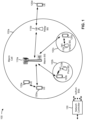
- Fig. 1 is provided as an example. Other examples may differ from what is described with regard to Fig. 1 .
- Fig. 2 shows a block diagram of a design 200 of base station 110 and UE 120, which may be one of the base stations and one of the UEs in Fig. 1 .
- Base station 110 may be equipped with T antennas 234a through 234t
- UE 120 may be equipped with R antennas 252a through 252r, where in general T ⁇ 1 and R ⁇ 1.
- a transmit processor 220 may receive data from a data source 212 for one or more UEs, select one or more modulation and coding schemes (MCS) for each UE based at least in part on channel quality indicators (CQIs) received from the UE, process (e.g., encode and modulate) the data for each UE based at least in part on the MCS(s) selected for the UE, and provide data symbols for all UEs. Transmit processor 220 may also process system information (e.g., for semi-static resource partitioning information (SRPI) and/or the like) and control information (e.g., CQI requests, grants, upper layer signaling, and/or the like) and provide overhead symbols and control symbols.
- MCS modulation and coding schemes
- CQIs channel quality indicators
- Transmit processor 220 may also process system information (e.g., for semi-static resource partitioning information (SRPI) and/or the like) and control information (e.g., CQI requests, grants, upper layer signal
- Transmit processor 220 may also generate reference symbols for reference signals (e.g., the cell-specific reference signal (CRS)) and synchronization signals (e.g., the primary synchronization signal (PSS) and secondary synchronization signal (SSS)).
- a transmit (TX) multiple-input multiple-output (MIMO) processor 230 may perform spatial processing (e.g., precoding) on the data symbols, the control symbols, the overhead symbols, and/or the reference symbols, if applicable, and may provide T output symbol streams to T modulators (MODs) 232a through 232t. Each modulator 232 may process a respective output symbol stream (e.g., for OFDM and/or the like) to obtain an output sample stream.
- Each modulator 232 may further process (e.g., convert to analog, amplify, filter, and upconvert) the output sample stream to obtain a downlink signal.
- T downlink signals from modulators 232a through 232t may be transmitted via T antennas 234a through 234t, respectively.
- the synchronization signals can be generated with location encoding to convey additional information.
- antennas 252a through 252r may receive the downlink signals from base station 110 and/or other base stations and may provide received signals to demodulators (DEMODs) 254a through 254r, respectively.
- Each demodulator 254 may condition (e.g., filter, amplify, downconvert, and digitize) a received signal to obtain input samples.
- Each demodulator 254 may further process the input samples (e.g., for OFDM and/or the like) to obtain received symbols.
- a MIMO detector 256 may obtain received symbols from all R demodulators 254a through 254r, perform MIMO detection on the received symbols if applicable, and provide detected symbols.
- a receive processor 258 may process (e.g., demodulate and decode) the detected symbols, provide decoded data for UE 120 to a data sink 260, and provide decoded control information and system information to a controller/processor 280.
- a channel processor may determine reference signal received power (RSRP), received signal strength indicator (RSSI), reference signal received quality (RSRQ), channel quality indicator (CQI), and/or the like.
- RSRP reference signal received power
- RSSI received signal strength indicator
- RSRQ reference signal received quality indicator
- CQI channel quality indicator
- one or more components of UE 120 may be included in a housing.
- a transmit processor 264 may receive and process data from a data source 262 and control information (e.g., for reports comprising RSRP, RSSI, RSRQ, CQI, and/or the like) from controller/processor 280. Transmit processor 264 may also generate reference symbols for one or more reference signals. The symbols from transmit processor 264 may be precoded by a TX MIMO processor 266 if applicable, further processed by modulators 254a through 254r (e.g., for DFT-s-OFDM, CP-OFDM, and/or the like), and transmitted to base station 110.
- control information e.g., for reports comprising RSRP, RSSI, RSRQ, CQI, and/or the like
- Transmit processor 264 may also generate reference symbols for one or more reference signals.
- the symbols from transmit processor 264 may be precoded by a TX MIMO processor 266 if applicable, further processed by modulators 254a through 254r (e.g., for DFT-
- the uplink signals from UE 120 and other UEs may be received by antennas 234, processed by demodulators 232, detected by a MIMO detector 236 if applicable, and further processed by a receive processor 238 to obtain decoded data and control information sent by UE 120.
- Receive processor 238 may provide the decoded data to a data sink 239 and the decoded control information to controller/processor 240.
- Base station 110 may include communication unit 244 and communicate to network controller 130 via communication unit 244.
- Network controller 130 may include communication unit 294, controller/processor 290, and memory 292.
- memory 242 and/or memory 282 may comprise a non-transitory computer-readable medium storing one or more instructions for wireless communication.
- the one or more instructions when executed (e.g., directly, or after compiling, converting, interpreting, and/or the like) by one or more processors of the base station 110 and/or the UE 120, may perform or direct operations of, for example, process 900 of Fig. 9 and/or other processes as described herein.
- executing instructions may include running the instructions, converting the instructions, compiling the instructions, interpreting the instructions, and/or the like.
- a scheduler 246 may schedule UEs for data transmission on the downlink and/or uplink.
- Figs. 3-5 are diagrams illustrating one or more examples of full-duplex operation modes, in accordance with various aspects of the present disclosure.
- a user equipment (UE) and a base station (BS) may communicate with each other using beams.
- a beam may be a downlink beam (e.g., on which information may be conveyed from the BS to the UE) or an uplink beam (e.g, on which information may be conveyed from the UE to the BS).
- the UE and the BS may be integrated access backhaul (IAB) wireless nodes.
- IAB integrated access backhaul
- a communication link between a UE and a BS may be referred to as half-duplex when the communication link includes only one of an uplink or a downlink or full-duplex when the communication link includes an uplink and a downlink.
- a full-duplex communication link may provide increased scalability of data rates on the link in comparison to a half-duplex communication link.
- different antenna elements, sub-arrays, or antenna panels of a wireless communication device may simultaneously or contemporaneously perform uplink and downlink communication.
- Full-duplex communication may present certain challenges in comparison to half-duplex communication.
- a wireless communication device e.g., a UE, a BA, and/or a wireless node
- a wireless communication device may experience self-interference between an uplink beam and a downlink beam of a full-duplex link or between components of the wireless communication device. This self-interference may complicate the monitoring of reference signals to detect beam failure.
- self-interference, cross-correlation, and/or the like may occur in a full-duplex communication link that may not occur in a half-duplex communication link.
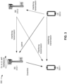
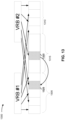
- an example wireless network 300 includes a BS 310-1 operating in a full-duplex operation mode.
- the BS 310-1 may receive an uplink from a UE 320-2 and transmit a downlink to a UE 320-1.
- the UE-320-1 and the UE 320-2 may be operating in a half-duplex operation mode.
- the BS 310-1 may experience downlink to uplink self-interference based at least in part on the downlink transmitted to UE 320-1 and the uplink received from UE 320-2.
- BS 310-1 may experience interfering transmissions from other wireless communication devices transmitting in the wireless network 300 (e.g., from a BS 310-2).
- UE 320-1 interfering transmissions from other wireless communication devices transmitting in the wireless network 300 (e.g., from the UE 320-2, from the BS 310-2, and/or the like).
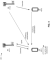
- an example wireless network 400 includes a UE 420-1 operating in a full-duplex operation mode.
- the UE 420-1 may transmit an uplink to a BS 410-1 and may receive a downlink from the BS 410-1.
- the BS 410-1 may be operating in a full-duplex operation mode.
- the UE 420-1 may experience uplink to downlink self-interreference based at least in part on the uplink transmitted to the BS 410-1 and the downlink received from the BS 410-1.
- the wireless network 400 may include other wireless communication devices, such as a BS 410-2 and a UE 420-2.
- the BS 410-2 may transmit a downlink to the UE-410-2.
- the UE 420-1 may experience an interfering transmission based at least in part on the transmission of the BS 410-2 and/or the UE 420-1.
- the downlink transmitted by the BS 410-2 may have an angular spread that may cause an interfering transmission to be received by the UE 420-1.
- an uplink transmitted by the UE 420-2 may have an angular spread that may cause an interfering transmission to be received by the UE 420-1.
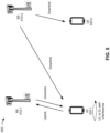
- an example wireless network 500 includes a UE 520-1 operating in a full-duplex operation mode.
- the UE 520-1 may transmit an uplink to a BS 510-1 and may receive a downlink from a BS 510-2.
- the UE 520-1 may include a multi transmission and reception (multi-TRP) architecture.
- the UE 520-1 may experience uplink to downlink self-interreference based at least in part on the uplink transmitted to the BS 510-1 and the downlink received from the BS 510-2.
- the BS 510-1 and the BS 510-2 may be operating in a half-duplex mode of operation.
- the BS 510-2 may transmit a downlink to a UE 520-2.
- the UE 520-1 may experience one or more interfering transmissions based at least in part on the transmissions of BS 510-1, BS 510-2, and/or UE 520-2.
- Figs. 3-5 are provided as examples. Other examples may differ from what is described with respect to Figs. 3-5 .
- Fig. 6 is a diagram illustrating one or more examples 600 of full-duplex types, in accordance with various aspects of the present disclosure.
- full-duplex operation may involve communications having both an uplink (UL) and a downlink (DL) at the same time (e.g., transmit and receive at the same time).
- the uplink and downlink may share resources (e.g., time resources and/or frequency resources) associated with the communications.
- a full-duplex communication may be an in-band full duplex (IBFD) mode (e.g., a mode that includes an uplink and a downlink that share the same time resources and/or frequency resources).
- IBFD mode may be a full overlap IBFD mode, such that the downlink resources may completely overlap the uplink resources (e.g., all of the uplink resources are shared with the downlink resources).
- a full overlap IBFD mode may have uplink resources that completely overlap the downlink resources.
- an IBFD communication may be a partial overlap IBFD mode, such that the downlink resources do not completely overlap the uplink resources (e.g., only some of the uplink resources are shared with the downlink resources).
- Fig. 6 is provided as an example. Other examples may differ from what is described with respect to Fig. 6 .
- a wireless communication standard or governing body may specify how a wireless spectrum is to be used.
- 3GPP may specify how wireless spectrum is to be used for the 5G/NR radio access technology and interface.
- a specification may indicate whether a band is to be used as paired spectrum or unpaired spectrum.
- a band in a paired spectrum may use a first frequency region for uplink communication and a second frequency region for downlink communication, where the first frequency region does not overlap the second frequency region.
- a paired band may have an uplink operating band and a downlink operating band that are configured to use non-overlapped frequency regions.
- FDD frequency division duplexing
- An unpaired band may allow downlink and uplink operations within a same frequency region (e.g., a same operating band). For example, an unpaired band may configure an uplink operating band and a downlink operating band in the same frequency range. Some deployments may use time division duplexing (TDD) in the unpaired band, where some time intervals (e.g., slots, sub-slots, and/or the like) are used for uplink communications and other time intervals are used for downlink communications. In this case, substantially the entire bandwidth of a component carrier may be used for a downlink communication or an uplink communication, depending on whether the communication is performed in a downlink slot, an uplink slot, or a special slot (in which downlink or uplink communications can be scheduled). Examples of unpaired bands include NR operating bands n40, n41, and n50, as specified by 3GPP TS 38.101-1.
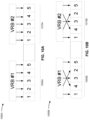
- the one or more VRB-to-PRB mapping rules may comprise mapping the first VRB to a first disjoint BWP segment without interleaving, or mapping the second VRB to a second disjoint BWP segment without interleaving, or a combination thereof.
- FIG. 10A illustrates a VRB-to-PRB mapping scheme 1000A in accordance with this approach, whereby a first VRB group (i.e., VRB #1) and a second VRB group (i.e., VRB #2) map directly to respective PRBs in a first disjoint BWP segment 1005A and a second disjoint BWP segment 1010A, respectively, without interleaving.
- a first VRB group i.e., VRB #1
- a second VRB group i.e., VRB #2
- the one or more VRB-to-PRB mapping rules may comprise mapping the first VRB to a first disjoint BWP segment with interleaving, and mapping the second VRB to a second disjoint BWP segment with interleaving that is independent relative to the interleaving associated with the first disjoint BWP segment.
- FIG. 10B illustrates a VRB-to-PRB mapping scheme 1000B in accordance with this approach, whereby a first VRB group (i.e., VRB #1) and a second VRB group (i.e., VRB #2) map directly to PRBs in a first disjoint BWP segment 1005B and a second disjoint BWP segment 1010B, respectively, with independent interleaving.
- a first VRB group i.e., VRB #1
- a second VRB group i.e., VRB #2
- the individual RBs of VRB #1 are interleaved with respect to each other, but not with respect to the individual RBs of VRB #2.
- the one or more VRB-to-PRB mapping rules may comprise mapping a respective VRB to a respective disjoint BWP segment with interleaving if the respective disjoint BWP segment is above a size threshold and without interleaving if the respective disjoint BWP segment is not above the size threshold.
- this particular VRB-to-PRB mapping rule may function to override one or more other VRB-to-PRB mapping rules that would otherwise dictate that interleaving be used.
- the one or more VRB-to-PRB mapping rules may comprise merging the first and second VRB groups, and then mapping the merged VRB group to the first and second disjoint BWP parts with interleaving.
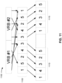
- the one or more VRB-to-PRB mapping rules may comprise jointly interleaving the first and second VRBs across the first and second disjoint BWP segments.
- FIG. 12 illustrates a VRB-to-PRB mapping scheme 1200 in accordance with this approach, whereby a first VRB group (i.e., VRB #1) and a second VRB group (i.e., VRB #2) are jointly interleaved across a first disjoint BWP segment 1205 and a second disjoint BWP segment 1210, respectively.
- a first VRB group i.e., VRB #1
- a second VRB group i.e., VRB #2
- the allocation of the first and second VRBs is across PRBs that overlap with an intervening BWP segment 1215 between the first and second disjoint BWP segments.
- one particular PRB 1220 to which VRB #2 is mapped overlaps with the intervening BWP segment 1215.
- the first and second disjoint BWP segments comprise DL data
- the intervening BWP segment comprises a GB, UL data, or a combination thereof. So, VRB #2's allocation of PRB 1220 may overlap with the GB and/or with one or UL data transmission. In other designs (e.g., where Type 0 or bitmap-based VRB-to-PRB mapping rule is used), the overlap can be avoided.
- the wireless node (which may correspond to UE or BS) may handle such an overlap, including but not limited to:
- FIG. 13 illustrates a VRB-to-PRB mapping scheme 1300 in accordance with an approach whereby the UE interprets an overlap as a cycling repetition at the UE.
- a first VRB group i.e., VRB #1
- a second VRB group i.e., VRB #2
- the allocation of the first and second VRBs is across PRBs that overlap with an intervening BWP segment 1315 between the first and second disjoint BWP segments.
- PRB 1320 to which VRB #2 is mapped overlaps with the intervening BWP segment 1315.
- the UE interprets PRB 1320 as a cycling repetition of another PRB that is not inside of the intervening BWP segment 1315, in this case, PRB 1325 which is part of the first disjoint BWP segment 1305.
- the one or more VRB-to-PRB mapping rules may comprise scheduling the DL data in the first and second disjoint BWP segments via a single resource indicator value (RIV) with a startpoint and length indicator that encompasses the intervening BWP segment.
- RIV resource indicator value
- a Type 1 allocation may be used whereby VRB #1 and VRB #2 are treated as a single PDSCH transmission that spans the first and second VRBs across the first and second disjoint BWP segments as well as an intervening BWP segment.
- FIG. 14 illustrates a VRB-to-PRB mapping scheme 1400 in accordance with this approach, whereby a consolidated VRB associated with a single RIV is interleaved across a first disjoint BWP segment 1405 and a second disjoint BWP segment 1410, respectively.
- the allocation of the VRB is across PRBs that overlap with an intervening BWP segment 1415 between the first and second disjoint BWP segments.
- one particular PRB 1420 to which VRB #2 is mapped overlaps with the intervening BWP segment 1415.
- the first and second disjoint BWP segments comprise DL data
- the intervening BWP segment comprises a GB, UL data, or a combination thereof.
- VRB #2's allocation of PRB 1420 may overlap with the GB and/or with one or UL data transmission.
- the overlap reflected in FIG. 14 with respect to PRB 1420 may be handled via any of the mechanisms described above with respect to the overlap of PRB 1220 in FIG. 12 (e.g., UE performing rate-matching only whereby PDSCH PRBs in the overlapping part are unavailable for PDSCH transmission, DL data omitted from this PRB, interpreted as error condition or cycling repetition, etc.).
- the overlap can be avoided.
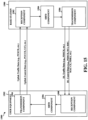
- FIG. 15 is a conceptual data flow diagram 1500 illustrating the data flow between different means/components in exemplary apparatuses 1502 and 1580 in accordance with an aspect of the disclosure.
- the apparatus 1502 may be a UE (e.g., UE 120) in communication with an apparatus 1580, which may be a base station (e.g., base station 110).
- UE e.g., UE 120
- base station e.g., base station 110
- the apparatus 1502 includes a transmission component 1504, which may correspond to transmitter circuitry in UE 120 as depicted in FIG. 2 , including controller/processor 280, antenna(s) 252a ... 252r, modulators(s) 254a ... 254r, TX MIMO processor 266, TX processor 264.
- the apparatus 1502 further includes SBFD component 1506, which may correspond to processor circuitry in UE 120 as depicted in FIG. 2 , including controller/processor 280, etc.
- the apparatus 1502 further includes a reception component 1508, which may correspond to receiver circuitry in UE 120 as depicted in FIG. 2 , including controller/processor 280, antenna(s) 252a ... 252r, demodulators(s) 254a ... 254r, MIMO detector 256, RX processor 258.
- the apparatus 1580 includes a reception component 1582, which may correspond to receiver circuitry in BS 110 as depicted in FIG. 2 , including controller/processor 240, antenna(s) 234a ... 234r, demodulators(s) 232a ... 232r, MIMO detector 236, RX processor 238, communication unit 244.
- the apparatus 1580 further includes a SBFD component 1584, which may correspond to processor circuitry in BS 110 as depicted in FIG. 2 , including controller/processor 240.
- the apparatus 1580 further includes a transmission component 1586, which may correspond to transmission circuitry in BS 110 as depicted in FIG. 2 , including e.g., controller/processor 240, antenna(s) 234a ... 234r, modulators(s) 232a ... 232r, Tx MIMO processor 230, TX processor 220, communication unit 244.
- the transmission component 1504 transmits uplink traffic data (e.g., PUSCH, etc.) and uplink control data (e.g., PUCCH, UCI, etc.) to the to the reception component 1582.
- uplink traffic data e.g., PUSCH, etc.
- uplink control data e.g., PUCCH, UCI, etc.
- the SBFD component 1584 determines VRB-to-PRB allocations for an SBFD slot, which may be based in part on the uplink communications from the apparatus 1502.
- the SBFD 1584 forwards the VRB-to-PRB allocations for the SBFD slot to the transmission component 1586, which transmits downlink traffic data (e.g., PDSCH) and downlink control data (e.g., PDCCH, DCI, RRC signaling, MAC-CEs, FDRA, etc.) to the reception component 1508 based on the VRB-to-PRB allocations for the SBFD slot.
- the SBFD component 1506 determines the VRB-to-PRB allocations for the SBFD slot processes the downlink data and/or schedules uplink data for transmission based on the determination.
- One or more components of the apparatus 1502 and apparatus 1580 may perform each of the blocks of the algorithm in the aforementioned flowchart of FIG. 9 . As such, each block in the aforementioned flowchart of FIG. 9 may be performed by a component and the apparatus 1502 and apparatus 1580 may include one or more of those components.
- the components may be one or more hardware components specifically configured to carry out the stated processes/algorithm, implemented by a processor configured to perform the stated processes/algorithm, stored within a computer-readable medium for implementation by a processor, or some combination thereof.
- FIG. 16 is a diagram 1600 illustrating an example of a hardware implementation for an apparatus 1502 employing a processing system 1614.
- the processing system 1614 may be implemented with a bus architecture, represented generally by the bus 1624.
- the bus 1624 may include any number of interconnecting buses and bridges depending on the specific application of the processing system 1614 and the overall design constraints.
- the bus 1624 links together various circuits including one or more processors and/or hardware components, represented by the processor 1604, the components 1504, 1506 and 1508, and the computer-readable medium / memory 1606.
- the bus 1624 may also link various other circuits such as timing sources, peripherals, voltage regulators, and power management circuits, which are well known in the art, and therefore, will not be described any further.
- the processing system 1614 may be coupled to a transceiver 1610.
- the transceiver 1610 is coupled to one or more antennas 1620.
- the transceiver 1610 provides a means for communicating with various other apparatus over a transmission medium.
- the transceiver 1610 receives a signal from the one or more antennas 1620, extracts information from the received signal, and provides the extracted information to the processing system 1614, specifically the reception component 1508.
- the transceiver 1610 receives information from the processing system 1614, specifically the transmission component 1504, and based on the received information, generates a signal to be applied to the one or more antennas 1620.
- the processing system 1614 includes a processor 1604 coupled to a computer-readable medium / memory 1606.
- the processor 1604 is responsible for general processing, including the execution of software stored on the computer-readable medium / memory 1606.
- the software when executed by the processor 1604, causes the processing system 1614 to perform the various functions described supra for any particular apparatus.
- the computer-readable medium / memory 1606 may also be used for storing data that is manipulated by the processor 1604 when executing software.
- the processing system 1614 further includes at least one of the components 1504, 1506 and 1508.
- the components may be software components running in the processor 1604, resident/stored in the computer readable medium / memory 1606, one or more hardware components coupled to the processor 1604, or some combination thereof.
- the processing system 1614 may be a component of the UE 120 of FIG. 2 and may include the memory 282, and/or at least one of the TX processor 264, the RX processor 258, and the controller/processor 280.
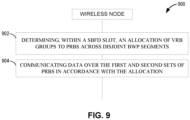
- the apparatus 1502 (e.g., a UE) for wireless communication includes means for determining, within a sub-band full duplex (SBFD) slot, an allocation of first and second virtual resource block (VRB) groups to physical resource blocks (PRBs) across first and second disjoint bandwidth part (BWP) segments based upon one or more VRB-to-PRB mapping rules, and means for communicating data over the first and second sets of PRBs in accordance with the allocation.
- SBFD sub-band full duplex
- VRB virtual resource block
- PRBs physical resource blocks
- BWP bandwidth part
- the aforementioned means may be one or more of the aforementioned components of the apparatus 1502 and/or the processing system 1614 of the apparatus 1502 configured to perform the functions recited by the aforementioned means.
- the processing system 1614 may include the TX processor 264, the RX processor 258, and the controller/processor 280.
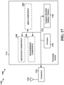
- FIG. 17 is a diagram 1700 illustrating an example of a hardware implementation for an apparatus 1580 employing a processing system 1714.
- the processing system 1714 may be implemented with a bus architecture, represented generally by the bus 1724.
- the bus 1724 may include any number of interconnecting buses and bridges depending on the specific application of the processing system 1714 and the overall design constraints.
- the bus 1724 links together various circuits including one or more processors and/or hardware components, represented by the processor 1704, the components 1582, 1584 and 1586, and the computer-readable medium / memory 1706.
- the bus 1724 may also link various other circuits such as timing sources, peripherals, voltage regulators, and power management circuits, which are well known in the art, and therefore, will not be described any further.
- the processor 1704 is responsible for general processing, including the execution of software stored on the computer-readable medium / memory 1706.
- the software when executed by the processor 1704, causes the processing system 1714 to perform the various functions described supra for any particular apparatus.
- the computer-readable medium / memory 1706 may also be used for storing data that is manipulated by the processor 1704 when executing software.
- the processing system 1714 further includes at least one of the components 1582, 1584 and 1586.
- the components may be software components running in the processor 1704, resident/stored in the computer readable medium / memory 1706, one or more hardware components coupled to the processor 1704, or some combination thereof.
- the processing system 1714 may be a component of the BS 110 of FIG. 2 and may include the memory 242, and/or at least one of the TX processor 220, the RX processor 238, and the controller/processor 240.
- the apparatus 1580 for wireless communication includes means for determining, within a sub-band full duplex (SBFD) slot, an allocation of first and second virtual resource block (VRB) groups to physical resource blocks (PRBs) across first and second disjoint bandwidth part (BWP) segments based upon one or more VRB-to-PRB mapping rules, and means for communicating data over the first and second sets of PRBs in accordance with the allocation.
- SBFD sub-band full duplex
- VRB virtual resource block
- PRBs physical resource blocks
- BWP bandwidth part
- the aforementioned means may be one or more of the aforementioned components of the apparatus 1580 and/or the processing system 1714 of the apparatus 1580 configured to perform the functions recited by the aforementioned means.
- the processing system 1714 may include the TX processor 220, the RX processor 238, and the controller/processor 240.
- satisfying a threshold may, depending on the context, refer to a value being greater than the threshold, greater than or equal to the threshold, less than the threshold, less than or equal to the threshold, equal to the threshold, not equal to the threshold, and/or the like.
- "at least one of: a, b, or c” is intended to cover a, b, c, a-b, a-c, b-c, and a-b-c, as well as any combination with multiples of the same element (e.g., a-a, a-a-a, a-a-b, a-a-c, a-b-b, a-c-c, b-b, b-b-b, b-b-c, c-c, and c-c-c or any other ordering of a, b, and c).
Landscapes
- Engineering & Computer Science (AREA)
- Signal Processing (AREA)
- Computer Networks & Wireless Communication (AREA)
- Mobile Radio Communication Systems (AREA)
Claims (15)
- Verfahren, das von einem drahtlosen Knoten (110, 120) durchgeführt wird, umfassend:Bestimmen (902), innerhalb eines Subband-Vollduplex-, SBFD-, Schlitzes zum gleichzeitigen Senden und Empfangen innerhalb des SBFD-Schlitzes, einer Zuordnung von ersten und zweiten virtuellen Ressourcenblock-, VRB-, Gruppen zu physikalischen Ressourcenblöcken, PRBs, über erste und zweite disjunkte Bandbreitenteil-, BWP-, Segmente innerhalb des SBFD-Schlitzes basierend auf einer oder mehreren VRB-zu-PRB-Abbildungsregeln; undKommunizieren (904) von Daten über die ersten und zweiten Sätze von PRBs gemäß der Zuordnung.
- Verfahren nach Anspruch 1, wobei die eine oder die mehreren VRB-zu-PRB-Abbildungsregeln das Abbilden des ersten VRB auf ein erstes disjunktes BWP-Segment ohne Verschachtelung oder das Abbilden des zweiten VRB auf ein zweites disjunktes BWP-Segment ohne Verschachtelung oder eine Kombination davon umfassen.
- Verfahren nach Anspruch 1, wobei die eine oder die mehreren VRB-zu-PRB-Abbildungsregeln das Abbilden des ersten VRB auf ein erstes disjunktes BWP-Segment mit Verschachtelung und das Abbilden des zweiten VRB auf ein zweites disjunktes BWP-Segment mit Verschachtelung, das unabhängig von der Verschachtelung ist, die dem ersten disjunkten BWP-Segment zugeordnet ist, umfassen.
- Verfahren nach Anspruch 1, wobei die eine oder die mehreren VRB-zu-PRB-Abbildungsregeln das Abbilden eines jeweiligen VRB auf ein jeweiliges disjunktes BWP-Segment mit Verschachtelung, wenn das jeweilige disjunkte BWP-Segment über einer Größenschwelle liegt, und ohne Verschachtelung, wenn das jeweilige disjunkte BWP-Segment nicht über der Größenschwelle liegt, umfassen.
- Verfahren nach Anspruch 1, wobei die eine oder die mehreren VRB-zu-PRB-Abbildungsregeln das Zusammenführen der ersten und zweiten VRB-Gruppen und dann das Abbilden der zusammengeführten VRB-Gruppe auf die ersten und zweiten disjunkten BWP-Teile mit Verschachtelung umfassen.
- Verfahren nach Anspruch 1, wobei die eine oder die mehreren VRB-zu-PRB-Abbildungsregeln das gemeinsame Verschachteln der ersten und zweiten VRBs über die ersten und zweiten disjunkten BWP-Segmente umfassen.
- Verfahren nach Anspruch 6, wobei die Zuordnung der ersten und zweiten PRBs über die ersten und zweiten disjunkten BWP-Segmente nur so erfolgt, dass ein intervenierendes BWP-Segment umgangen wird.
- Verfahren nach Anspruch 6, wobei die Zuordnung der ersten und zweiten VRBs über PRBs erfolgt, die sich mit einem intervenierenden BWP-Segment zwischen den ersten und zweiten disjunkten BWP-Segmenten überlappen.
- Verfahren nach Anspruch 8,wobei die ersten und zweiten disjunkten BWP-Segmente Downlink-, DL-, Daten umfassen,wobei das intervenierende BWP-Segment ein Schutzband-, GB-, Uplink-, UL-, Daten oder eine Kombination davon umfasst.
- Verfahren nach Anspruch 9,wobei DL-Daten aus dem intervenierenden BWP-Segment ausgelassen werden, oderwobei ein Benutzergerät, UE, das dem überlappenden VRB zugeordnet ist, eine Ratenanpassung an jeweiligen PRBs des intervenierenden BWP-Segments durchführt, oderwobei jeder VRB einer Priorität zugeordnet ist und von dem UE angenommen wird, dass DL-Daten nur in Bezug auf einen überlappenden VRB vorhanden sind, der einer höchsten Priorität zugeordnet ist, oderwobei die Überlappung als eine Fehlerbedingung an dem UE interpretiert wird, oderwobei die Überlappung als zyklische Wiederholung an dem UE interpretiert wird, odereine beliebige Kombination davon.
- Verfahren nach Anspruch 9, wobei die DL-Daten in den ersten und zweiten disjunkten BWP-Segmenten über einen einzelnen Ressourcenindikatorwert, RIV, mit einem Startpunkt- und Längenindikator, der das intervenierende BWP-Segment einschließt, geplant werden.
- Verfahren nach Anspruch 1,wobei der drahtlose Knoten (110, 120) einer Basisstation (110) entspricht, oderwobei der drahtlose Knoten (110, 120) einem Benutzergerät (120), UE, entspricht.
- Drahtloser Knoten (110, 120), umfassend Mittel zum Durchführen des Verfahrens nach einem der Ansprüche 1 bis 12.
- Nichtflüchtiges computerlesbares Medium, das darauf gespeicherte Anweisungen enthält, die, wenn sie auf mindestens einem Prozessor in einem drahtlosen Knoten (110, 120) ausgeführt werden, den mindestens einen Prozessor veranlassen, das Verfahren nach einem der Ansprüche 1 bis 12 durchzuführen.
- Computerprogramm, umfassend Anweisungen, die, wenn sie auf mindestens einem Prozessor in einem drahtlosen Knoten (110, 120) ausgeführt werden, den mindestens einen Prozessor veranlassen, das Verfahren nach einem der Ansprüche 1 bis 12 durchzuführen.
Applications Claiming Priority (2)
| Application Number | Priority Date | Filing Date | Title |
|---|---|---|---|
| GR20200100225 | 2020-05-05 | ||
| PCT/US2021/016834 WO2021225656A1 (en) | 2020-05-05 | 2021-02-05 | Vrb-to-prb allocation for disjoint bwp segments |
Publications (3)
| Publication Number | Publication Date |
|---|---|
| EP4147402A1 EP4147402A1 (de) | 2023-03-15 |
| EP4147402B1 true EP4147402B1 (de) | 2025-07-02 |
| EP4147402C0 EP4147402C0 (de) | 2025-07-02 |
Family
ID=74845079
Family Applications (1)
| Application Number | Title | Priority Date | Filing Date |
|---|---|---|---|
| EP21709256.8A Active EP4147402B1 (de) | 2020-05-05 | 2021-02-05 | Vrb-zu-prb-zuweisung für disjunkte bwp-segmente |
Country Status (8)
| Country | Link |
|---|---|
| US (1) | US20230135832A1 (de) |
| EP (1) | EP4147402B1 (de) |
| KR (1) | KR20230004551A (de) |
| CN (1) | CN115398851B (de) |
| BR (1) | BR112022021618A2 (de) |
| PH (1) | PH12022552523A1 (de) |
| TW (1) | TWI902793B (de) |
| WO (1) | WO2021225656A1 (de) |
Families Citing this family (13)
| Publication number | Priority date | Publication date | Assignee | Title |
|---|---|---|---|---|
| KR20240127961A (ko) * | 2021-12-31 | 2024-08-23 | 엘지전자 주식회사 | 무선 통신 시스템에서 상향링크 또는 하향링크 송수신을 수행하는 방법 및 장치 |
| WO2023197275A1 (zh) * | 2022-04-14 | 2023-10-19 | 北京小米移动软件有限公司 | 资源确定、资源配置方法和装置、通信装置及存储介质 |
| US20260012945A1 (en) * | 2022-07-22 | 2026-01-08 | Sharp Kabushiki Kaisha | Apparatus and methods with downlink channel resource mapping |
| CN117560124A (zh) * | 2022-08-02 | 2024-02-13 | 大唐移动通信设备有限公司 | 资源确定方法、装置、终端及网络侧设备 |
| KR20240020068A (ko) * | 2022-08-05 | 2024-02-14 | 삼성전자주식회사 | 무선 통신 시스템에서 전이중 통신을 위한 스케줄링 방법 및 장치 |
| KR20240066217A (ko) * | 2022-11-04 | 2024-05-14 | 삼성전자주식회사 | 무선 통신 시스템에서 전 이중 통신을 위한 하향링크 데이터 채널 전송 방법 및 장치 |
| WO2024098192A1 (en) * | 2022-11-07 | 2024-05-16 | Nec Corporation | Method, device and computer readable medium for communications |
| CN118354436A (zh) * | 2023-01-16 | 2024-07-16 | 北京紫光展锐通信技术有限公司 | 资源确定方法、装置及用户设备 |
| JP2025538654A (ja) * | 2023-01-19 | 2025-11-28 | 新華三技術有限公司 | データ伝送方法、装置及び電子デバイス |
| CN118509996A (zh) * | 2023-02-16 | 2024-08-16 | 华为技术有限公司 | 资源分配方法与装置 |
| CN116346288A (zh) * | 2023-04-25 | 2023-06-27 | 赛特斯信息科技股份有限公司 | 5g网络系统中实现自适应梳搜索处理的方法、装置、处理器及其计算机可读存储介质 |
| CN119729812A (zh) * | 2023-09-27 | 2025-03-28 | 上海朗帛通信技术有限公司 | 一种用于无线通信的节点中的方法和装置 |
| WO2025171623A1 (en) * | 2024-02-16 | 2025-08-21 | Nokia Shanghai Bell Co., Ltd. | Resource mapping in context of sbfd |
Family Cites Families (7)
| Publication number | Priority date | Publication date | Assignee | Title |
|---|---|---|---|---|
| KR100925441B1 (ko) * | 2008-01-07 | 2009-11-06 | 엘지전자 주식회사 | 분산형 가상자원블록 스케쥴링 방법 |
| WO2011127404A2 (en) * | 2010-04-09 | 2011-10-13 | Huawei Technologies Co., Ltd. | System and method for transmitting control information |
| US10440710B2 (en) * | 2014-09-09 | 2019-10-08 | Telefonaktiebolaget Lm Ericsson (Publ) | Resource structure and indication for Rel-13 MTC UE |
| CN109152019A (zh) * | 2017-06-16 | 2019-01-04 | 华为技术有限公司 | 资源映射的方法和装置 |
| US12114291B2 (en) * | 2017-11-10 | 2024-10-08 | Qualcomm Incorporated | Virtual resource block to physical resource block mapping in new radio |
| CN109995467B (zh) * | 2018-01-03 | 2020-09-01 | 电信科学技术研究院 | 一种资源映射方法及装置、设备 |
| WO2019137403A1 (en) * | 2018-01-09 | 2019-07-18 | Mediatek Singapore Pte. Ltd. | Resource allocation and vrb-to-prb mapping in mobile communications |
-
2021
- 2021-02-05 EP EP21709256.8A patent/EP4147402B1/de active Active
- 2021-02-05 CN CN202180028555.5A patent/CN115398851B/zh active Active
- 2021-02-05 PH PH1/2022/552523A patent/PH12022552523A1/en unknown
- 2021-02-05 BR BR112022021618A patent/BR112022021618A2/pt unknown
- 2021-02-05 WO PCT/US2021/016834 patent/WO2021225656A1/en not_active Ceased
- 2021-02-05 US US17/995,683 patent/US20230135832A1/en active Pending
- 2021-02-05 KR KR1020227037890A patent/KR20230004551A/ko active Pending
- 2021-05-05 TW TW110116177A patent/TWI902793B/zh active
Also Published As
| Publication number | Publication date |
|---|---|
| KR20230004551A (ko) | 2023-01-06 |
| PH12022552523A1 (en) | 2024-02-12 |
| BR112022021618A2 (pt) | 2023-02-28 |
| TWI902793B (zh) | 2025-11-01 |
| TW202147879A (zh) | 2021-12-16 |
| EP4147402A1 (de) | 2023-03-15 |
| CN115398851A (zh) | 2022-11-25 |
| WO2021225656A1 (en) | 2021-11-11 |
| CN115398851B (zh) | 2024-07-16 |
| US20230135832A1 (en) | 2023-05-04 |
| EP4147402C0 (de) | 2025-07-02 |
Similar Documents
| Publication | Publication Date | Title |
|---|---|---|
| EP4147402B1 (de) | Vrb-zu-prb-zuweisung für disjunkte bwp-segmente | |
| EP3874639B1 (de) | Transportblockübertragungswiederholung unter verwendung verschiedener räumlicher parameter | |
| EP3977803B1 (de) | Frequenzduplexen im ungepaarten spektrum | |
| WO2021022435A1 (en) | Configuration of a control resource set and common search space for initial access by low tier user equipment | |
| EP3692754B1 (de) | Techniken und vorrichtungen für synchronisierungsdesign | |
| EP3753361B1 (de) | Uplink-übertragungskollisionsmanagement | |
| US11968681B2 (en) | Resource allocation for piggyback downlink control information | |
| US11910405B2 (en) | Determining time domain resources for uplink cancellation | |
| US11800558B2 (en) | Configuring listen before talk bandwidth monitoring | |
| EP4128638B1 (de) | Getrennte ressourcenanzeige für vollduplex-betrieb | |
| WO2021134771A1 (en) | Using time offset in downlink control information that schedules multiple cells | |
| EP4179798B1 (de) | Meldung von leistungsreserven je teilband | |
| US11638291B2 (en) | Joint modulation and coding scheme indication for downlink and uplink allocations in sub-band full-duplex | |
| US12532302B2 (en) | Physical downlink control channel coexistence for different user equipment categories | |
| US12356403B2 (en) | Signaling an indication of a sidelink transmission | |
| EP3981209B1 (de) | Multiplexkommunikation von benutzergeräten mit unterstützung von unterschiedlichen übertragungszeitintervalllängen | |
| US12408196B2 (en) | Contiguous uplink transmission in contention-based access systems | |
| WO2021248296A1 (en) | Resource sharing between base stations and anchor user equipments on sidelink channels |
Legal Events
| Date | Code | Title | Description |
|---|---|---|---|
| STAA | Information on the status of an ep patent application or granted ep patent |
Free format text: STATUS: UNKNOWN |
|
| STAA | Information on the status of an ep patent application or granted ep patent |
Free format text: STATUS: THE INTERNATIONAL PUBLICATION HAS BEEN MADE |
|
| PUAI | Public reference made under article 153(3) epc to a published international application that has entered the european phase |
Free format text: ORIGINAL CODE: 0009012 |
|
| STAA | Information on the status of an ep patent application or granted ep patent |
Free format text: STATUS: REQUEST FOR EXAMINATION WAS MADE |
|
| 17P | Request for examination filed |
Effective date: 20221004 |
|
| AK | Designated contracting states |
Kind code of ref document: A1 Designated state(s): AL AT BE BG CH CY CZ DE DK EE ES FI FR GB GR HR HU IE IS IT LI LT LU LV MC MK MT NL NO PL PT RO RS SE SI SK SM TR |
|
| DAV | Request for validation of the european patent (deleted) | ||
| DAX | Request for extension of the european patent (deleted) | ||
| GRAP | Despatch of communication of intention to grant a patent |
Free format text: ORIGINAL CODE: EPIDOSNIGR1 |
|
| STAA | Information on the status of an ep patent application or granted ep patent |
Free format text: STATUS: GRANT OF PATENT IS INTENDED |
|
| INTG | Intention to grant announced |
Effective date: 20250219 |
|
| GRAS | Grant fee paid |
Free format text: ORIGINAL CODE: EPIDOSNIGR3 |
|
| GRAA | (expected) grant |
Free format text: ORIGINAL CODE: 0009210 |
|
| STAA | Information on the status of an ep patent application or granted ep patent |
Free format text: STATUS: THE PATENT HAS BEEN GRANTED |
|
| AK | Designated contracting states |
Kind code of ref document: B1 Designated state(s): AL AT BE BG CH CY CZ DE DK EE ES FI FR GB GR HR HU IE IS IT LI LT LU LV MC MK MT NL NO PL PT RO RS SE SI SK SM TR |
|
| REG | Reference to a national code |
Ref country code: GB Ref legal event code: FG4D |
|
| REG | Reference to a national code |
Ref country code: CH Ref legal event code: EP |
|
| REG | Reference to a national code |
Ref country code: DE Ref legal event code: R096 Ref document number: 602021033291 Country of ref document: DE |
|
| REG | Reference to a national code |
Ref country code: IE Ref legal event code: FG4D |
|
| U01 | Request for unitary effect filed |
Effective date: 20250716 |
|
| U07 | Unitary effect registered |
Designated state(s): AT BE BG DE DK EE FI FR IT LT LU LV MT NL PT RO SE SI Effective date: 20250723 |
|
| PG25 | Lapsed in a contracting state [announced via postgrant information from national office to epo] |
Ref country code: IS Free format text: LAPSE BECAUSE OF FAILURE TO SUBMIT A TRANSLATION OF THE DESCRIPTION OR TO PAY THE FEE WITHIN THE PRESCRIBED TIME-LIMIT Effective date: 20251102 |
|
| PG25 | Lapsed in a contracting state [announced via postgrant information from national office to epo] |
Ref country code: NO Free format text: LAPSE BECAUSE OF FAILURE TO SUBMIT A TRANSLATION OF THE DESCRIPTION OR TO PAY THE FEE WITHIN THE PRESCRIBED TIME-LIMIT Effective date: 20251002 |
|
| PG25 | Lapsed in a contracting state [announced via postgrant information from national office to epo] |
Ref country code: HR Free format text: LAPSE BECAUSE OF FAILURE TO SUBMIT A TRANSLATION OF THE DESCRIPTION OR TO PAY THE FEE WITHIN THE PRESCRIBED TIME-LIMIT Effective date: 20250702 |
|
| PG25 | Lapsed in a contracting state [announced via postgrant information from national office to epo] |
Ref country code: GR Free format text: LAPSE BECAUSE OF FAILURE TO SUBMIT A TRANSLATION OF THE DESCRIPTION OR TO PAY THE FEE WITHIN THE PRESCRIBED TIME-LIMIT Effective date: 20251003 |
|
| PG25 | Lapsed in a contracting state [announced via postgrant information from national office to epo] |
Ref country code: CZ Free format text: LAPSE BECAUSE OF FAILURE TO SUBMIT A TRANSLATION OF THE DESCRIPTION OR TO PAY THE FEE WITHIN THE PRESCRIBED TIME-LIMIT Effective date: 20250702 |
|
| PG25 | Lapsed in a contracting state [announced via postgrant information from national office to epo] |
Ref country code: PL Free format text: LAPSE BECAUSE OF FAILURE TO SUBMIT A TRANSLATION OF THE DESCRIPTION OR TO PAY THE FEE WITHIN THE PRESCRIBED TIME-LIMIT Effective date: 20250702 |
|
| PG25 | Lapsed in a contracting state [announced via postgrant information from national office to epo] |
Ref country code: RS Free format text: LAPSE BECAUSE OF FAILURE TO SUBMIT A TRANSLATION OF THE DESCRIPTION OR TO PAY THE FEE WITHIN THE PRESCRIBED TIME-LIMIT Effective date: 20251002 |
|
| PG25 | Lapsed in a contracting state [announced via postgrant information from national office to epo] |
Ref country code: ES Free format text: LAPSE BECAUSE OF FAILURE TO SUBMIT A TRANSLATION OF THE DESCRIPTION OR TO PAY THE FEE WITHIN THE PRESCRIBED TIME-LIMIT Effective date: 20250702 |