EP3874639B1 - Transportblockübertragungswiederholung unter verwendung verschiedener räumlicher parameter - Google Patents
Transportblockübertragungswiederholung unter verwendung verschiedener räumlicher parameter Download PDFInfo
- Publication number
- EP3874639B1 EP3874639B1 EP19797458.7A EP19797458A EP3874639B1 EP 3874639 B1 EP3874639 B1 EP 3874639B1 EP 19797458 A EP19797458 A EP 19797458A EP 3874639 B1 EP3874639 B1 EP 3874639B1
- Authority
- EP
- European Patent Office
- Prior art keywords
- repetition
- size
- aspects
- different
- symbols
- Prior art date
- Legal status (The legal status is an assumption and is not a legal conclusion. Google has not performed a legal analysis and makes no representation as to the accuracy of the status listed.)
- Active
Links
Images


Classifications
-
- H—ELECTRICITY
- H04—ELECTRIC COMMUNICATION TECHNIQUE
- H04L—TRANSMISSION OF DIGITAL INFORMATION, e.g. TELEGRAPHIC COMMUNICATION
- H04L1/00—Arrangements for detecting or preventing errors in the information received
- H04L1/0001—Systems modifying transmission characteristics according to link quality, e.g. power backoff
- H04L1/0006—Systems modifying transmission characteristics according to link quality, e.g. power backoff by adapting the transmission format
-
- H—ELECTRICITY
- H04—ELECTRIC COMMUNICATION TECHNIQUE
- H04L—TRANSMISSION OF DIGITAL INFORMATION, e.g. TELEGRAPHIC COMMUNICATION
- H04L1/00—Arrangements for detecting or preventing errors in the information received
- H04L1/08—Arrangements for detecting or preventing errors in the information received by repeating transmission, e.g. Verdan system
-
- H—ELECTRICITY
- H04—ELECTRIC COMMUNICATION TECHNIQUE
- H04L—TRANSMISSION OF DIGITAL INFORMATION, e.g. TELEGRAPHIC COMMUNICATION
- H04L5/00—Arrangements affording multiple use of the transmission path
- H04L5/0001—Arrangements for dividing the transmission path
- H04L5/0014—Three-dimensional division
- H04L5/0023—Time-frequency-space
-
- H—ELECTRICITY
- H04—ELECTRIC COMMUNICATION TECHNIQUE
- H04L—TRANSMISSION OF DIGITAL INFORMATION, e.g. TELEGRAPHIC COMMUNICATION
- H04L5/00—Arrangements affording multiple use of the transmission path
- H04L5/003—Arrangements for allocating sub-channels of the transmission path
- H04L5/0048—Allocation of pilot signals, i.e. of signals known to the receiver
- H04L5/0051—Allocation of pilot signals, i.e. of signals known to the receiver of dedicated pilots, i.e. pilots destined for a single user or terminal
-
- H—ELECTRICITY
- H04—ELECTRIC COMMUNICATION TECHNIQUE
- H04L—TRANSMISSION OF DIGITAL INFORMATION, e.g. TELEGRAPHIC COMMUNICATION
- H04L5/00—Arrangements affording multiple use of the transmission path
- H04L5/003—Arrangements for allocating sub-channels of the transmission path
- H04L5/0078—Timing of allocation
- H04L5/0082—Timing of allocation at predetermined intervals
-
- H—ELECTRICITY
- H04—ELECTRIC COMMUNICATION TECHNIQUE
- H04L—TRANSMISSION OF DIGITAL INFORMATION, e.g. TELEGRAPHIC COMMUNICATION
- H04L5/00—Arrangements affording multiple use of the transmission path
- H04L5/0091—Signalling for the administration of the divided path, e.g. signalling of configuration information
- H04L5/0094—Indication of how sub-channels of the path are allocated
-
- H—ELECTRICITY
- H04—ELECTRIC COMMUNICATION TECHNIQUE
- H04L—TRANSMISSION OF DIGITAL INFORMATION, e.g. TELEGRAPHIC COMMUNICATION
- H04L5/00—Arrangements affording multiple use of the transmission path
- H04L5/02—Channels characterised by the type of signal
- H04L5/06—Channels characterised by the type of signal the signals being represented by different frequencies
- H04L5/10—Channels characterised by the type of signal the signals being represented by different frequencies with dynamo-electric generation of carriers; with mechanical filters or demodulators
-
- H—ELECTRICITY
- H04—ELECTRIC COMMUNICATION TECHNIQUE
- H04W—WIRELESS COMMUNICATION NETWORKS
- H04W72/00—Local resource management
- H04W72/04—Wireless resource allocation
- H04W72/044—Wireless resource allocation based on the type of the allocated resource
- H04W72/0446—Resources in time domain, e.g. slots or frames
-
- H—ELECTRICITY
- H04—ELECTRIC COMMUNICATION TECHNIQUE
- H04W—WIRELESS COMMUNICATION NETWORKS
- H04W72/00—Local resource management
- H04W72/20—Control channels or signalling for resource management
- H04W72/23—Control channels or signalling for resource management in the downlink direction of a wireless link, i.e. towards a terminal
-
- H—ELECTRICITY
- H04—ELECTRIC COMMUNICATION TECHNIQUE
- H04W—WIRELESS COMMUNICATION NETWORKS
- H04W76/00—Connection management
- H04W76/20—Manipulation of established connections
- H04W76/27—Transitions between radio resource control [RRC] states
-
- H—ELECTRICITY
- H04—ELECTRIC COMMUNICATION TECHNIQUE
- H04L—TRANSMISSION OF DIGITAL INFORMATION, e.g. TELEGRAPHIC COMMUNICATION
- H04L1/00—Arrangements for detecting or preventing errors in the information received
- H04L1/0078—Avoidance of errors by organising the transmitted data in a format specifically designed to deal with errors, e.g. location
-
- H—ELECTRICITY
- H04—ELECTRIC COMMUNICATION TECHNIQUE
- H04L—TRANSMISSION OF DIGITAL INFORMATION, e.g. TELEGRAPHIC COMMUNICATION
- H04L5/00—Arrangements affording multiple use of the transmission path
- H04L5/003—Arrangements for allocating sub-channels of the transmission path
- H04L5/0044—Allocation of payload; Allocation of data channels, e.g. PDSCH or PUSCH
Definitions
- aspects of the present disclosure generally relate to wireless communication and to techniques and apparatuses for transport block transmission using different spatial parameters.
- Wireless communication systems are widely deployed to provide various telecommunication services such as telephony, video, data, messaging, and broadcasts.
- Typical wireless communication systems may employ multiple-access technologies capable of supporting communication with multiple users by sharing available system resources (e.g., bandwidth, transmit power, and/or the like).
- multiple-access technologies include code division multiple access (CDMA) systems, time division multiple access (TDMA) systems, frequency-division multiple access (FDMA) systems, orthogonal frequency-division multiple access (OFDMA) systems, single-carrier frequency-division multiple access (SC-FDMA) systems, time division synchronous code division multiple access (TD-SCDMA) systems, and Long Term Evolution (LTE).
- LTE/LTE-Advanced is a set of enhancements to the Universal Mobile Telecommunications System (UMTS) mobile standard promulgated by the Third Generation Partnership Project (3GPP).
- UMTS Universal Mobile Telecommunications System
- a wireless communication network may include a number of base stations (BSs) that can support communication for a number of user equipment (UEs).
- a user equipment (UE) may communicate with a base station (BS) via the downlink and uplink.
- the downlink (or forward link) refers to the communication link from the BS to the UE
- the uplink (or reverse link) refers to the communication link from the UE to the BS.
- a BS may be referred to as a Node B, a gNB, an access point (AP), a radio head, a transmit receive point (TRP), a new radio (NR) BS, a 5G Node B, and/or the like.
- WO 2016/119232 A1 relates to a device for determining a repetition number of a physical data channel under coverage enhancement.
- New radio which may also be referred to as 5G, is a set of enhancements to the LTE mobile standard promulgated by the Third Generation Partnership Project (3GPP).
- 3GPP Third Generation Partnership Project
- NR is designed to better support mobile broadband Internet access by improving spectral efficiency, lowering costs, improving services, making use of new spectrum, and better integrating with other open standards using orthogonal frequency division multiplexing (OFDM) with a cyclic prefix (CP) (CP-OFDM) on the downlink (DL), using CP-OFDM and/or SC-FDM (e.g., also known as discrete Fourier transform spread OFDM (DFT-s-OFDM)) on the uplink (UL), as well as supporting beamforming, multiple-input multiple-output (MIMO) antenna technology, and carrier aggregation.
- OFDM orthogonal frequency division multiplexing
- SC-FDM e.g., also known as discrete Fourier transform spread OFDM (DFT-s-OFDM)
- MIMO multiple-input multiple-output
- aspects may be described herein using terminology commonly associated with 3G and/or 4G wireless technologies, aspects of the present disclosure can be applied in other generation-based communication systems, such as 5G and later, including NR technologies.
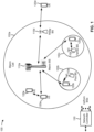
- Fig. 1 is a diagram illustrating a network 100 in which aspects of the present disclosure may be practiced.
- the network 100 may be an LTE network or some other wireless network, such as a 5G or NR network.
- Wireless network 100 may include a number of BSs 110 (shown as BS 110a, BS 110b, BS 110c, and BS 110d) and other network entities.
- a BS is an entity that communicates with user equipment (UEs) and may also be referred to as a base station, a NR BS, a Node B, a gNB, a 5G node B (NB), an access point, a transmit receive point (TRP), and/or the like.
- Each BS may provide communication coverage for a particular geographic area.
- the term "cell" can refer to a coverage area of a BS and/or a BS subsystem serving this coverage area, depending on the context in which the term is used.
- a BS may provide communication coverage for a macro cell, a pico cell, a femto cell, and/or another type of cell.
- a macro cell may cover a relatively large geographic area (e.g., several kilometers in radius) and may allow unrestricted access by UEs with service subscription.
- a pico cell may cover a relatively small geographic area and may allow unrestricted access by UEs with service subscription.
- a femto cell may cover a relatively small geographic area (e.g., a home) and may allow restricted access by UEs having association with the femto cell (e.g., UEs in a closed subscriber group (CSG)).
- a BS for a macro cell may be referred to as a macro BS.
- a BS for a pico cell may be referred to as a pico BS.
- a BS for a femto cell may be referred to as a femto BS or a home BS.
- a BS 110a may be a macro BS for a macro cell 102a
- a BS 110b may be a pico BS for a pico cell 102b
- a BS 110c may be a femto BS for a femto cell 102c.
- a BS may support one or multiple (e.g., three) cells.
- the terms "eNB”, “base station”, “NR BS”, “gNB”, “TRP”, “AP”, “node B", “5G NB”, and “cell” may be used interchangeably herein.
- a cell may not necessarily be stationary, and the geographic area of the cell may move according to the location of a mobile BS.
- the BSs may be interconnected to one another and/or to one or more other BSs or network nodes (not shown) in the access network 100 through various types of backhaul interfaces such as a direct physical connection, a virtual network, and/or the like using any suitable transport network.
- Wireless network 100 may also include relay stations.
- a relay station is an entity that can receive a transmission of data from an upstream station (e.g., a BS or a UE) and send a transmission of the data to a downstream station (e.g., a UE or a BS).
- a relay station may also be a UE that can relay transmissions for other UEs.
- a relay station 110d may communicate with macro BS 110a and a UE 120d in order to facilitate communication between BS 110a and UE 120d.
- a relay station may also be referred to as a relay BS, a relay base station, a relay, and/or the like.
- Wireless network 100 may be a heterogeneous network that includes BSs of different types, e.g., macro BSs, pico BSs, femto BSs, relay BSs, and/or the like. These different types of BSs may have different transmit power levels, different coverage areas, and different impact on interference in wireless network 100.
- macro BSs may have a high transmit power level (e.g., 5 to 40 Watts) whereas pico BSs, femto BSs, and relay BSs may have lower transmit power levels (e.g., 0.1 to 2 Watts).
- a network controller 130 may couple to a set of BSs and may provide coordination and control for these BSs.
- Network controller 130 may communicate with the BSs via a backhaul.
- the BSs may also communicate with one another, e.g., directly or indirectly via a wireless or wireline backhaul.
- UEs 120 may be dispersed throughout wireless network 100, and each UE may be stationary or mobile.
- a UE may also be referred to as an access terminal, a terminal, a mobile station, a subscriber unit, a station, and/or the like.
- a UE may be a cellular phone (e.g., a smart phone), a personal digital assistant (PDA), a wireless modem, a wireless communication device, a handheld device, a laptop computer, a cordless phone, a wireless local loop (WLL) station, a tablet, a camera, a gaming device, a netbook, a smartbook, an ultrabook, medical device or equipment, biometric sensors/devices, wearable devices (smart watches, smart clothing, smart glasses, smart wrist bands, smart jewelry (e.g., smart ring, smart bracelet)), an entertainment device (e.g., a music or video device, or a satellite radio), a vehicular component or sensor, smart meters/sensors, industrial manufacturing equipment, a global positioning system device, or any other suitable device that is configured to communicate via a wireless or wired medium.
- a cellular phone e.g., a smart phone
- PDA personal digital assistant
- WLL wireless local loop
- MTC and eMTC UEs include, for example, robots, drones, remote devices, such as sensors, meters, monitors, location tags, and/or the like, that may communicate with a base station, another device (e.g., remote device), or some other entity.
- a wireless node may provide, for example, connectivity for or to a network (e.g., a wide area network such as Internet or a cellular network) via a wired or wireless communication link.
- Some UEs may be considered Internet-of Things (IoT) devices, and/or may be implemented as may be implemented as NB-IoT (narrowband internet of things) devices.
- Some UEs may be considered a Customer Premises Equipment (CPE).
- UE 120 may be included inside a housing that houses components of UE 120, such as processor components, memory components, and/or the like.
- any number of wireless networks may be deployed in a given geographic area.
- Each wireless network may support a particular RAT and may operate on one or more frequencies.
- a RAT may also be referred to as a radio technology, an air interface, and/or the like.
- a frequency may also be referred to as a carrier, a frequency channel, and/or the like.
- Each frequency may support a single RAT in a given geographic area in order to avoid interference between wireless networks of different RATs.
- NR or 5G RAT networks may be deployed.
- two or more UEs 120 may communicate directly using one or more sidelink channels (e.g., without using a base station 110 as an intermediary to communicate with one another).
- the UEs 120 may communicate using peer-to-peer (P2P) communications, device-to-device (D2D) communications, a vehicle-to-everything (V2X) protocol (e.g., which may include a vehicle-to-vehicle (V2V) protocol, a vehicle-to-infrastructure (V2I) protocol, and/or the like), a mesh network, and/or the like).
- V2X vehicle-to-everything
- the UE 120 may perform scheduling operations, resource selection operations, and/or other operations described elsewhere herein as being performed by the base station 110.
- Fig. 1 is provided merely as an example. Other examples may differ from what was described with regard to Fig. 1 .
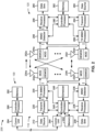
- Fig. 2 shows a block diagram of a design 200 of base station 110 and UE 120, which may be one of the base stations and one of the UEs in Fig. 1 .
- Base station 110 may be equipped with T antennas 234a through 234t
- UE 120 may be equipped with R antennas 252a through 252r, where in general T ⁇ 1 and R ⁇ 1.
- a transmit processor 220 may receive data from a data source 212 for one or more UEs, select one or more modulation and coding schemes (MCS) for each UE based at least in part on channel quality indicators (CQIs) received from the UE, process (e.g., encode and modulate) the data for each UE based at least in part on the MCS(s) selected for the UE, and provide data symbols for all UEs. Transmit processor 220 may also process system information (e.g., for semi-static resource partitioning information (SRPI) and/or the like) and control information (e.g., CQI requests, grants, upper layer signaling, and/or the like) and provide overhead symbols and control symbols.
- MCS modulation and coding schemes
- CQIs channel quality indicators
- Transmit processor 220 may also process system information (e.g., for semi-static resource partitioning information (SRPI) and/or the like) and control information (e.g., CQI requests, grants, upper layer signal
- Transmit processor 220 may also generate reference symbols for reference signals (e.g., the cell-specific reference signal (CRS)) and synchronization signals (e.g., the primary synchronization signal (PSS) and secondary synchronization signal (SSS)).
- a transmit (TX) multiple-input multiple-output (MIMO) processor 230 may perform spatial processing (e.g., precoding) on the data symbols, the control symbols, the overhead symbols, and/or the reference symbols, if applicable, and may provide T output symbol streams to T modulators (MODs) 232a through 232t. Each modulator 232 may process a respective output symbol stream (e.g., for OFDM and/or the like) to obtain an output sample stream.
- Each modulator 232 may further process (e.g., convert to analog, amplify, filter, and upconvert) the output sample stream to obtain a downlink signal.
- T downlink signals from modulators 232a through 232t may be transmitted via T antennas 234a through 234t, respectively.
- the synchronization signals can be generated with location encoding to convey additional information.
- antennas 252a through 252r may receive the downlink signals from base station 110 and/or other base stations and may provide received signals to demodulators (DEMODs) 254a through 254r, respectively.
- Each demodulator 254 may condition (e.g., filter, amplify, downconvert, and digitize) a received signal to obtain input samples.
- Each demodulator 254 may further process the input samples (e.g., for OFDM and/or the like) to obtain received symbols.
- a MIMO detector 256 may obtain received symbols from all R demodulators 254a through 254r, perform MIMO detection on the received symbols if applicable, and provide detected symbols.
- a receive processor 258 may process (e.g., demodulate and decode) the detected symbols, provide decoded data for UE 120 to a data sink 260, and provide decoded control information and system information to a controller/processor 280.
- a channel processor may determine reference signal received power (RSRP), received signal strength indicator (RSSI), reference signal received quality (RSRQ), channel quality indicator (CQI), and/or the like.
- RSRP reference signal received power
- RSSI received signal strength indicator
- RSRQ reference signal received quality indicator
- CQI channel quality indicator
- one or more components of UE 120 may be included in a housing.
- a transmit processor 264 may receive and process data from a data source 262 and control information (e.g., for reports comprising RSRP, RSSI, RSRQ, CQI, and/or the like) from controller/processor 280. Transmit processor 264 may also generate reference symbols for one or more reference signals. The symbols from transmit processor 264 may be precoded by a TX MIMO processor 266 if applicable, further processed by modulators 254a through 254r (e.g., for DFT-s-OFDM, CP-OFDM, and/or the like), and transmitted to base station 110.
- control information e.g., for reports comprising RSRP, RSSI, RSRQ, CQI, and/or the like
- Transmit processor 264 may also generate reference symbols for one or more reference signals.
- the symbols from transmit processor 264 may be precoded by a TX MIMO processor 266 if applicable, further processed by modulators 254a through 254r (e.g., for DFT-
- the uplink signals from UE 120 and other UEs may be received by antennas 234, processed by demodulators 232, detected by a MIMO detector 236 if applicable, and further processed by a receive processor 238 to obtain decoded data and control information sent by UE 120.
- Receive processor 238 may provide the decoded data to a data sink 239 and the decoded control information to controller/processor 240.
- Base station 110 may include communication unit 244 and communicate to network controller 130 via communication unit 244.
- Network controller 130 may include communication unit 294, controller/processor 290, and memory 292.
- Controller/processor 240 of base station 110, controller/processor 280 of UE 120, and/or any other component(s) of Fig. 2 may perform one or more techniques associated with transport block transmission using different spatial parameters, as described in more detail elsewhere herein.
- controller/processor 240 of base station 110, controller/processor 280 of UE 120, and/or any other component(s) of Fig. 2 may perform or direct operations of, for example, process 900 of Fig. 9 , process 1000 of Fig. 10 , process 1100 of Fig. 11 , process 1200 of Fig. 12 , process 1300 of Fig. 13 , and/or other processes as described herein.
- Memories 242 and 282 may store data and program codes for base station 110 and UE 120, respectively.
- a scheduler 246 may schedule UEs for data transmission on the downlink and/or uplink.
- UE 120 and/or base station 110 may include means for determining a first set of parameters associated with a first transport block (TB) repetition of a TB and a second set of parameters associated with a second TB repetition of the TB; means for determining a TB size of the TB based at least in part on the first set of parameters, the second set of parameters, or both the first set of parameters and the second set of parameters; and/or the like.
- such means may include one or more components of UE 120 and/or base station 110 described in connection with Fig. 2 .
- UE 120 may include means for receiving a grant for a first TB repetition, wherein the grant indicates a first mini-slot in which the first TB repetition is scheduled; means for determining one or more subsequent mini-slots, that occur after the first mini slot, in which one or more subsequent TB repetitions are scheduled based at least in part on a mini-slot pattern configuration or one or more parameters of the first TB repetition; and/or the like.
- UE 120 may include means for receiving an indication of a first set of symbols and a second set of symbols in which a single communication is scheduled; means for transmitting or receiving the single communication in the first set of symbols and the second set of symbols using a first spatial parameter for the first set of symbols and a second spatial parameter for the second set of symbols; and/or the like.
- such means may include one or more components of UE 120 described in connection with Fig. 2 .
- base station 110 may include means for transmitting a grant for a first TB repetition, wherein the grant indicates a first mini-slot in which the first TB repetition is scheduled; means for scheduling one or more subsequent TB repetitions in one or more subsequent mini-slots that occur after the first mini slot, wherein the one or more subsequent mini-slots are determined based at least in part on a mini-slot pattern configuration or one or more parameters of the first TB repetition; and/or the like.
- base station 110 may include means for transmitting an indication of a first set of symbols and a second set of symbols in which a single communication is scheduled; means for transmitting or receiving the single communication in the first set of symbols and the second set of symbols using a first spatial parameter for the first set of symbols and a second spatial parameter for the second set of symbols; and/or the like.
- such means may include one or more components of base station 110 described in connection with Fig. 2 .
- Fig. 2 is provided merely as an example. Other examples may differ from what was described with regard to Fig. 2 .
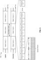
- Fig. 3 shows an example frame structure 300 in a telecommunications system (e.g., NR).
- the transmission timeline for each of the downlink and uplink may be partitioned into units of radio frames (sometimes referred to as frames).
- Each radio frame may have a predetermined duration (e.g., 10 milliseconds (ms)) and may be partitioned into a set of Z (Z ⁇ 1) subframes (e.g., with indices of 0 through Z-1).
- Each subframe may have a predetermined duration (e.g., 1ms) and may include a set of slots (e.g., 2 m slots per subframe are shown in Fig.
- Each slot may include a set of L symbol periods.
- each slot may include fourteen symbol periods (e.g., as shown in Fig. 3 ), seven symbol periods, or another number of symbol periods.
- the subframe may include 2L symbol periods, where the 2L symbol periods in each subframe may be assigned indices of 0 through 2L-1.
- a slot may include one or more mini-slots.
- a mini-slot may include a number of symbols (e.g., 2 symbols, 3 symbols, 4 symbols, and/or the like) capable of being scheduled as a unit.
- a scheduling unit may be frame-based, subframe-based, slot-based, mini-slot based, symbol-based, and/or the like.
- transmissions may be repeated in multiple transmission time intervals (TTIs), such as multiple slots, multiple mini-slots, multiple sets of symbols, and/or the like, such as for multi-slot transmission and/or slot aggregation (e.g., on a physical downlink shared channel (PDSCH), a physical uplink shared channel (PUSCH), a physical uplink control channel (PUCCH), and/or the like).
- TTIs transmission time intervals
- PDSCH physical downlink shared channel
- PUSCH physical uplink shared channel
- PUCCH physical uplink control channel
- one, two, four, or eight repetitions may be used in a time period (P).
- different repetitions may use different redundancy versions of a communication.
- such repetition schemes may be used to achieve higher reliability and/or lower latency, such as for ultra-reliable low latency communication (URLLC), uplink grant-free communication, and/or the like.
- URLLC ultra-reliable low latency communication
- URLLC ultra-reliable low latency communication
- a wireless communication structure or a TTI may refer to a periodic time-bounded communication unit defined by a wireless communication standard and/or protocol. Additionally, or alternatively, different configurations of wireless communication structures and/or TTIs than those shown in Fig. 3 may be used.
- Fig. 3 is provided as an example. Other examples may differ from what was described with regard to Fig. 3 .
- Fig. 4 shows an example slot format 410 with a normal cyclic prefix.
- the available time frequency resources may be partitioned into resource blocks (RBs).
- Each resource block may cover a set to of subcarriers (e.g., 12 subcarriers) in one slot and may include a number of resource elements.
- Each resource element may cover one subcarrier in one symbol period (e.g., in time) and may be used to send one modulation symbol, which may be a real or complex value.
- New radio may refer to radios configured to operate according to a new air interface (e.g., other than Orthogonal Frequency Divisional Multiple Access (OFDMA)-based air interfaces) or fixed transport layer (e.g., other than Internet Protocol (IP)).
- OFDM Orthogonal Frequency Divisional Multiple Access
- IP Internet Protocol
- NR may utilize OFDM with a CP (herein referred to as cyclic prefix OFDM or CP-OFDM) and/or SC-FDM on the uplink, may utilize CP-OFDM on the downlink and include support for half-duplex operation using TDD.
- NR may, for example, utilize OFDM with a CP (herein referred to as CP-OFDM) and/or discrete Fourier transform spread orthogonal frequency-division multiplexing (DFT-s-OFDM) on the uplink, may utilize CP-OFDM on the downlink and include support for half-duplex operation using TDD.
- NR may include Enhanced Mobile Broadband (eMBB) service targeting wide bandwidth (e.g., 80 megahertz (MHz) and beyond), millimeter wave (mmW) targeting high carrier frequency (e.g., 60 gigahertz (GHz)), massive MTC (mMTC) targeting non-backward compatible MTC techniques, and/or mission critical targeting ultra reliable low latency communications (URLLC) service.
- eMBB Enhanced Mobile Broadband
- mmW millimeter wave
- mMTC massive MTC
- URLLC ultra reliable low latency communications
- NR resource blocks may span 12 sub-carriers with a sub-carrier bandwidth of 60 or 120 kilohertz (kHz) over a 0.1 millisecond (ms) duration.
- Each radio frame may include 40 slots and may have a length of 10 ms. Consequently, each slot may have a length of 0.25 ms.
- Each slot may indicate a link direction (e.g., DL or UL) for data transmission and the link direction for each slot may be dynamically switched.
- Each slot may include DL/UL data as well as DL/UL control data.
- NR may support a different air interface, other than an OFDM-based interface.
- NR networks may include entities such central units or distributed units.
- Fig. 4 is provided as an example. Other examples may differ from what was described with regard to Fig. 4 .
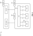
- Fig. 5 illustrates an example logical architecture of a distributed RAN 500, according to aspects of the present disclosure.
- a 5G access node 506 may include an access node controller (ANC) 502.
- the ANC 502 may be a central unit (CU) of the distributed RAN 500.
- the backhaul interface to the next generation core network (NG-CN) 504 may terminate at the ANC 502.
- the backhaul interface to neighboring next generation access nodes (NG-ANs) may terminate at the ANC 502.
- the ANC 502 may include one or more TRPs 508 (which may also be referred to as BSs, NR BSs, Node Bs, 5G NBs, APs, gNB, or some other term).
- TRPs 508 may be used interchangeably with "cell.”
- multiple TRPs 508 may be included in a single base station 110. Additionally, or alternatively, different TRPs 508 may be included in different base stations 110.
- a TRP 508 may be a distributed unit (DU).
- a TRP 508 may be connected to a single ANC 502 or multiple ANCs 502.
- the TRP 508 may be connected to more than one ANC 502.
- a TRP 508 may include one or more antenna ports.
- the TRPs 508 may be configured to individually (e.g., using dynamic selection) or jointly (e.g., using joint transmission) serve traffic to a UE 120.
- multiple TRPs 508 may transmit the same communication (e.g., the same transport block, PDSCH communication, and/or the like) in different TTIs (e.g., slots, mini-slots, and/or the like) using different spatial parameters (e.g., different quasi co-location (QCL) parameters, different transmission configuration indicator (TCI) states, different precoding parameters, different beamforming parameters, and/or the like).
- different spatial parameters e.g., different quasi co-location (QCL) parameters, different transmission configuration indicator (TCI) states, different precoding parameters, different beamforming parameters, and/or the like.
- a UE 120 may transmit the same communication (e.g., the same transport block, PUSCH communication, PUCCH communication, and/or the like) in different TTIs using different spatial parameters (e.g., different spatial domain filters, different spatial relations, different precoding parameters, different beamforming parameters, and/or the like), such as when the UE 120 is transmitting to different TRPs 508.
- different spatial parameters e.g., different spatial domain filters, different spatial relations, different precoding parameters, different beamforming parameters, and/or the like
- the local architecture of RAN 500 may be used to illustrate fronthaul definition.
- the architecture may be defined to support fronthauling solutions across different deployment types. For example, the architecture may be based at least in part on transmit network capabilities (e.g., bandwidth, latency, and/or jitter).
- the architecture may share features and/or components with LTE.
- the next generation AN (NG-AN) 510 may support dual connectivity with NR.
- the NG-AN 510 may share a common fronthaul for LTE and NR.
- the architecture may enable cooperation between and among TRPs 508. For example, cooperation may be preset within a TRP 508 and/or across TRPs 508 via the ANC 502. In some aspects, no inter-TRP interface may be needed/present.
- a dynamic configuration of split logical functions may be present within the architecture of RAN 500.
- the packet data convergence protocol (PDCP), radio link control (RLC), media access control (MAC) protocol, and/or the like may be adaptably placed at the ANC 502 or TRP 508.
- a base station 110 may include a central unit (CU) (e.g., ANC 502) and/or one or more distributed units (e.g., one or more TRPs 508).
- CU central unit
- distributed units e.g., one or more TRPs 508
- Fig. 5 is provided merely as an example. Other examples may differ from what was described with regard to Fig. 5 .
- Fig. 6 is a diagram illustrating an example 600 of transport block transmission using different spatial parameters, in accordance with various aspects of the present disclosure.
- a transmitter 605 and a receiver 610 may communicate with one another in a wireless communication system.
- the transmitter 605 and/or the receiver 610 may be a wireless communication device, such as a base station 110, a UE 120, and/or the like.
- the transmitter 605 is a base station 110 and the receiver 610 is a UE 120.
- the transmitter 605 is a UE 120 and the receiver 610 is a base station 110.
- Transport blocks (TBs) transmitted in different TTIs may be associated with different parameters used to determine respective transport block (TB) sizes of those TBs.
- a parameter used to determine a size of a TB may be referred to as a TB size determination parameter, and may include, for example, a modulation and coding scheme (MCS) used for the TB, a number of resource elements allocated for the TB, a number of layers (e.g., spatial layers) to be used to transmit the TB, and/or the like.
- MCS modulation and coding scheme
- those TBs may have different TB sizes if those TBs are associated with different TB size determination parameters.
- a TB size may be determined for different TB repetitions, which would violate the requirement that the TB in each repetition be the same size.
- demodulation reference signal (DMRS) sharing may be used across TB repetitions, where only some of the TB repetitions include DMRS to reduce DMRS overhead.
- DMRS demodulation reference signal
- different TB repetitions would include different numbers of symbols (e.g., resource elements), which would lead to different TB sizes.
- those TRPs may be permitted to flexibly schedule respective TB repetitions (e.g., using a different number of symbols or different mini-slot sizes), thereby resulting in different numbers of symbols for different TB repetitions, which would lead to different TB sizes.
- different TB repetitions may be scheduled using a different number of symbols and/or different mini-slot sizes to avoid crossing a slot boundary for a particular TB repetition.
- different TRPs may have different channel conditions in relation to a UE 120 (e.g., particularly when the TRPs are not co-located within the same base station 110), which may lead to different MCS parameters, different numbers of spatial layers, and/or the like being used by the different TRPs for respective TB repetitions, which would lead to different TB sizes.
- a TB size for each TB repetition, of a set of TB repetitions (e.g., an initial TB repetition and one or more other TB repetitions, which may be subsequent to the initial TB repetition or transmitted using a different set of RBs and/or a different set of spatial layers), is determined independently for each TB repetition, then the transmitter 605 and/or the receiver 610 may determine different TB sizes for different TB repetitions, which would prevent the same TB from being repeated.
- Some techniques and apparatuses described herein permit the transmitter 605 and the receiver 610 to determine TB sizes for TB repetitions such that all TB repetitions have the same size, thereby enabling TB repetitions.
- the transmitter 605 and the receiver 610 may apply the same technique or rule for TB size determination, thereby reducing ambiguity and resulting in fewer communication errors. Additional details are described below.
- a first TB repetition (shown as TB repetition 1) may be scheduled in a first TTI (e.g., a first slot, a first mini-slot, a first set of symbols, and/or the like), and is associated with a first set of TB size determination parameters.
- the first set of TB size determination parameters includes a first MCS, a first number of resource elements (REs), a first number of layers (e.g., MIMO layers, spatial layers, and/or the like), and/or the like.
- the term "repetition” may refer to a communication that is transmitted more than one time, and includes the initial transmission of that communication as well as each subsequent transmission of that communication. In some aspects, such repetitions may be transmitted without using hybrid automatic repeat request (HARQ) feedback.
- HARQ hybrid automatic repeat request
- a second TB repetition (shown as TB repetition 2) may be scheduled in a second TTI (e.g., a second slot, a second mini-slot, a second set of symbols, and/or the like), and is associated with a second set of TB size determination parameters.
- the second set of TB size determination parameters includes a second MCS, a second number of REs, a second number of spatial layers, and/or the like.
- the first TB repetition and the second TB repetition may be scheduled in, transmitted in, and/or received in different TTIs (e.g., in the case of time-division multiplexing (TDM)).
- TDM time-division multiplexing
- the first TB repetition and the second TB repetition may be scheduled in, transmitted in, and/or received in different sets of REs and/or RBs (e.g., in the case of frequency-division multiplexing (FDM)). Additionally, or alternatively, the first TB repetition and the second TB repetition may be scheduled in, transmitted in, and/or received in different spatial layers (e.g., in the case of spatial-division multiplexing (SDM)). In some aspects, the first TB and the second TB may be transmitted in the same TTI but with different parameters, as shown (e.g., different spatial layers, different numbers of REs, different RBs, and/or the like).
- sets of TB size determination parameters may be indicated in a radio resource control (RRC) message, in downlink control information (DCI), and/or the like.
- RRC radio resource control
- DCI downlink control information
- the transmitter 605 determines a TB size for a repeated TB using a rule.
- the receiver 610 determines the TB size for the repeated TB using the rule.
- the rule is a common rule that is commonly applied by both the transmitter 605 and the receiver 610, thereby reducing ambiguity and reducing communication errors. Application of the rule results in a determination of a same TB size for multiple TB repetitions, even if those TB repetitions are associated with different TB size determination parameters.
- the rule may be pre-specified according to a wireless communication standard. Additionally, or alternatively, the rule may be pre-configured according to a configuration message communicated between the transmitter 605 and the receiver 610 (e.g., in an RRC message and/or the like).
- the rule may be based at least in part on the first set of TB size determination parameters and/or the second set of TB size determination parameters (and/or or one or more other sets of TB size determination parameters for one or more other TB repetitions).
- the transmitter 605 and the receiver 610 may determine the TB size for the multiple TB repetitions based at least in part on one or more sets of TB size determination parameters of multiple sets of TB size determination parameters corresponding to the multiple TB repetitions.
- only the first set of TB size determination parameters, associated with the first TB repetition may be used to determine the TB size.
- a pre-specified and/or pre-configured rule may indicate that the TB size for all TB repetitions is to be determined using TB size determination parameters of only the initial TB repetition. This may conserve resources (e.g., processing resources, memory resources, and/or the like) by reducing or eliminating calculations using other sets of TB size determination parameters.
- the TB size is determined based at least in part on a function of a first TB size determined using the first set of TB size determination parameters and a second TB size determined using the second set of TB size determination parameters (and or one or more other TB sizes determined using one or more other sets of TB size determination parameters associated with one or more other TB repetitions). For example, TB sizes are calculated for each TB repetition (e.g., using corresponding TB size determination parameters), and a function is applied to those calculated TB sizes to determine a common TB size to be used for all TB repetitions.
- the function includes a minimum TB size of the calculated TB sizes, a maximum TB size of the calculated TB sizes, an average TB size of the TB sizes, and/or the like.
- the TB repetitions may be flexibly configured to account for different scenarios, such as different network conditions (e.g., traffic load and/or the like), different channel conditions, and/or the like.
- the TB size may be determined using only a single set of TB size determination parameters corresponding to a specific TB repetition.
- a base station 110 may indicate the specific TB repetition to a UE 120 (e.g., in DCI, in an RRC message, and/or the like).
- the specific TB repetition may be a TB repetition associated with a specific spatial parameter (e.g., QCL parameter, TCI state, spatial domain filter, and/or the like).
- the specific spatial parameter may be a spatial parameter that satisfies a condition, such as a spatial parameter with the lowest value among all spatial parameters for all TB repetitions, a spatial parameter with the highest value among all spatial parameters for all TB repetitions, a spatial parameter that matches a default value, and/or the like.
- the specific spatial parameter may be pre-specified in a wireless communication standard, may be pre-configured in a configuration message, may be communicated between the transmitter 605 and the receiver 610, and/or the like.
- the TB size may be determined based at least in part on a joint determination that is a function of the first set of TB size determination parameters and the second set of TB size determination parameters (and one or more other sets of TB size determination parameters associated with one or more other TB repetitions). In this case, the TB size may be determined as a function of all of the TB size determination parameters of all TB repetitions, without first calculating individual TB sizes for each TB repetition.
- the transmitter 605 or the receiver 610 may transmit, to the other of the transmitter 650 or the receiver 610, the rule to be applied to determine the TB size for the multiple TB repetitions.
- a base station 110 may transmit, and a UE 120 may receive, an indication of the rule.
- the indication may identify a specific TB repetition, and the set of TB size determination parameters corresponding to that TB repetition may be used to determine the TB size for all TB repetitions.
- one or more other rules may be indicated, as described above.
- the rule may be indicated in an RRC message (e.g., an RRC configuration message, an RRC reconfiguration message, and/or the like), in DCI, and/or the like.
- the TB repetitions may be scheduled and/or transmitted in the PUSCH. In some aspects, when the transmitter 605 is a base station 110, the TB repetitions may be scheduled and/or transmitted n the PDSCH. In some aspects, different base stations 110 and/or TRPs 508 may schedule and/or transmit different TB repetitions. In all of these cases, the UE 120 and the base station 110 (and/or the TRPs 508) may both apply the same rule when determining a TB size for TB repetitions, thereby enabling TB repetition that uses the same TB size across all repetitions, reducing ambiguity, and reducing communication errors.
- Fig. 6 is provided as an example. Other examples may differ from what was described with respect to Fig. 6 .
- Fig. 7 is a diagram illustrating another example 700 of transport block transmission using different spatial parameters, in accordance with various aspects of the present disclosure.
- a TB may be repeated in multiple mini-slots. However, this may consume additional control resources (e.g., on a physical downlink control channel (PDCCH)) if a grant were to be transmitted for each TB repetition (e.g., with control information for the TB repetition, such as a resource allocation and/or other TB parameters).
- PDCCH physical downlink control channel
- Some techniques and apparatuses described herein permit a single grant (e.g., a downlink grant) to be used to schedule multiple TB repetitions, thereby conserving network resources and device resources (e.g., processing resources, memory resources, battery power, and/or the like) that would otherwise be consumed to transmit and/or process multiple grants corresponding to the multiple TB repetitions.
- additional resources may be conserved by using control information for a single TB repetition (e.g., the first or initial TB repetition) to determine control information for other (e.g., subsequent) TB repetitions (e.g., according to a configuration, which may be transmitted once, in an RRC message, instead of multiple times in DCI). Additional details are described below.
- a base station 110 may transmit, and a UE 120 may receive, a mini-slot pattern configuration to be used for TB repetition.
- the mini-slot pattern configuration may indicate a pattern of mini-slots (e.g., in a time domain) for a time period.
- the time period may be indicated in the mini-slot pattern configuration. Additionally, or alternatively, the time period may be pre-specified according to a wireless communication standard.
- the time period may include, for example, a number of slots (e.g., 1 slot, 2 slots, 3 slots, and/or the like), a number of symbols (e.g., 12 symbols, 14 symbols, 24 symbols, 28 symbols, 36 symbols, 42 symbols, and/or the like), and/or the like.
- the time period may depend on whether slots are configured with a normal cyclic prefix (e.g., with 14 symbols) or an extended cyclic prefix (e.g., with 12 symbols).
- the mini-slot pattern configuration may be indicated in an RRC message.
- a mini-slot pattern configuration may indicate a number of mini-slots included in the time period and the symbols occupied by each of the mini-slots.
- the mini-slot pattern configuration may indicate the set of symbols occupied by a mini-slot by indicating a starting symbol and an ending symbol of the mini-slot.
- the mini-slot pattern configuration may indicate the set of symbols occupied by a mini-slot by indicating a starting symbol and a duration (e.g., a length, a number of symbols, and/or the like) of the mini-slot.
- the mini-slot pattern may be configured such that none of the individual mini-slots, indicated in the mini-slot pattern, cross a slot boundary, thereby reducing complexity (e.g., since processing by the UE 120 and/or the base station 110 may be slot-based).
- each mini-slot, included in the mini-slot pattern may be self-contained within a single slot.
- a mini-slot pattern configuration may be indicated for a time period of two slots, where each slot includes 12 symbols (e.g., with an extended cyclic prefix).
- the mini-slot pattern configuration may indicate that a first mini-slot (shown as Mini slot 1) occupies symbols 2 and 3 of the first slot, that a second mini-slot (shown as Mini slot 2) occupies symbols 6 and 7 of the first slot, that a third mini-slot (shown as Mini slot 3) occupies symbols 9, 10, and 11 of the first slot, that a fourth mini-slot (shown as Mini slot 4) occupies symbols 1 and 2 of the second slot, and so on.
- different mini-slots in the mini-slot pattern configuration may be configured with different lengths (e.g., 2 symbols, 3 symbols, 4 symbols, and/or the like).
- all of the mini-slots of a specific mini-slot pattern may have the same length.
- the base station 110 may transmit, and the UE 120 may receive, a grant (e.g., DCI) for a first TB repetition (e.g., an initial TB repetition).
- the grant may indicate a first mini-slot (e.g., a first set of symbols) in which the first TB repetition is scheduled.
- the grant is scheduled, transmitted, and received in symbol 3 of the first slot (e.g., in the PDCCH), and indicates that the first TB repetition occurs in symbols 4, 5, and 6 of the first slot (e.g., in the PDSCH or the PUSCH), as shown by reference number 720.
- the mini-slot in which the first TB repetition is scheduled, transmitted, and/or received does not need to be included in the mini-slot pattern indicated by the mini-slot pattern configuration. However, in some aspects, the mini-slot in which the first TB repetition is scheduled, transmitted, and/or received may be included in the mini-slot pattern.
- one or more subsequent TB repetitions may be scheduled, transmitted, and/or received based at least in part on the mini-slot pattern configuration.
- one or more subsequent mini-slots corresponding to the one or more subsequent TB repetitions, may occur after the first mini-slot in which the first TB repetition is scheduled.
- the number of subsequent mini-slots may be determined based at least in part on a number of TB repetitions (e.g., an aggregation level, which may be indicated in the grant), and the symbols occupied by those TB repetitions may be determined based at least in part on the mini-slot pattern.
- the mini-slot(s) for the subsequent TB repetition(s) may have a starting symbol that occurs after an ending symbol of the first mini-slot in which the first TB repetition is scheduled.
- the first TB repetition is scheduled in a first mini-slot that ends in symbol 6 of the first slot.
- Mini slot 1 and Mini slot 2 cannot be subsequent mini-slots because Mini slot 1 occurs entirely before the first TB repetition and Mini slot 2 overlaps with the first TB repetition.
- Mini slot 1 and Mini slot 2 do not start after an ending symbol of the first TB repetition (e.g., symbol 6 of the first slot).
- Mini slot 3 and Mini slot 4 can be subsequent mini-slots because both Mini slot 3 and Mini slot 4 start after the end of the first TB repetition.
- the TB would be repeated in the scheduled mini-slot (e.g., symbols 4, 5, and 6 of the first slot) and Mini slot 3 (e.g., symbols 9, 10, and 11 of the first slot). If the number of repetitions is greater than two, then the TB would be repeated in the scheduled mini-slot (e.g., symbols 4, 5, and 6 of the first slot), Mini slot 3 (e.g., symbols 9, 10, and 11 of the first slot), Mini slot 4 (e.g., symbols 1 and 2 of the second slot), and potentially one or more other mini-slots include in the mini-slot pattern, depending on the number of repetitions.
- the scheduled mini-slot e.g., symbols 4, 5, and 6 of the first slot
- Mini slot 3 e.g., symbols 9, 10, and 11 of the first slot
- Mini slot 4 e.g., symbols 1 and 2 of the second slot
- one or more other mini-slots include in the mini-slot pattern, depending on the number of repetitions.
- the one or more subsequent TB repetitions, that occur after the first TB repetition may be scheduled, transmitted, and/or received based at least in part on one or more parameters of the first TB repetition, such as a starting symbol of the first TB repetition, a length of the first TB repetition, an ending symbol of the first TB repetition, a time domain resource allocation of the first TB repetition, and/or the like.
- the grant for the first TB repetition may schedule multiple (e.g., two, three, or more) contiguous TB repetitions.
- the grant may indicate a length of the first TB repetition and a starting symbol for the first TB repetition.
- the UE 120 may infer the starting symbol of the second TB repetition using the length of the first repetition and the starting symbol of the first TB repetition. For example, starting symbol of the first repetition plus the length of the first TB repetition may indicate the end of the first TB repetition. The UE 120 may determine that the second TB repetition occurs in a next consecutive symbol after the end of the first TB repetition.
- one or more parameters for the first TB repetition may be used for one or more subsequent TB repetitions.
- TB parameters may conserve network resources and control information overhead by reusing a set of TB parameters, indicated in the grant, for multiple TB repetitions.
- a TB parameter may include an MCS, a frequency domain allocation (e.g., frequency resources in which the TB repetitions are scheduled), and/or the like, which may be indicated once (e.g., in the grant) and used for multiple TB repetitions.
- some parameters may differ between the first TB repetition and one of more subsequent TB repetitions, such as a spatial parameter (e.g., a TCI state, a QCL parameter, a spatial domain filter, and/or the like), a redundancy version, and/or the like.
- a spatial parameter e.g., a TCI state, a QCL parameter, a spatial domain filter, and/or the like
- the parameters that differ across TB repetitions may be indicated in the grant, in an RRC message, and/or the like.
- a parameter is not indicated for a subsequent TB repetition (e.g., in the grant, in DCI, in an RRC message, and/or the like)
- the UE 120 may determine that the parameter is the same for the first TB repetition and the subsequent TB repetition.
- the grant may indicate a redundancy version (RV) for a TB repetition other than the first TB repetition.
- the grant may explicitly indicate the redundancy version using a redundancy version identifier.
- the grant may indicate a redundancy version offset.
- the UE 120 may determine a redundancy version for a subsequent TB repetition (e.g., a second TB repetition) by applying the redundancy version offset to a redundancy version of a prior TB repetition (e.g., the first TB repetition).
- the redundancy version offset may wrap around (e.g., from RV0, RV1, RV2, RV3, back to RV0 in the case of four redundancy versions).
- the RV offset may be indicated in an RRC message.
- DCI may indicate whether to operate in a single TRP transmission mode or a multi-TRP transmission mode, to permit dynamic switching between these modes.
- an index value in a field of DCI e.g., a TCI index value in a TCI field
- the table may indicate a number of TRPs (e.g., a number of spatial parameters) and the spatial parameter value(s) to be used for those TRPs.
- only the index value e.g., the TCI index value
- the index value may point to an entry (e.g., a row) of the table, and that entry may indicate the number of TRPs and the spatial parameter(s) for those TRPs.
- the index value and a number of TB repetitions may be used to determine the number of TRPs and the spatial parameter(s) for those TRP(s).
- different entries e.g., rows
- spatial parameter(s) e.g., QCL parameter(s), TCI state(s), and/or the like
- a length of the entry or row may indicate the number of TRPs, and different entries (e.g., rows) may have different lengths.
- a first length e.g., length 1
- a second length e.g., greater than 1
- the length may indicate the number of TRPs in the multi-TRP transmission mode (e.g., two TRPs, three TRPs, and/or the like).
- the number of TB repetitions may be used to identify multiple entries (e.g., rows) in the table (e.g., entries having the same length, corresponding to the number of TB repetitions), and the TCI index value may be used to identify a specific entry of those multiple entries.
- different entries of the same length, corresponding to the same number of TRPs may include different spatial parameter values for those TRPs.
- the number of TB repetitions may be used to determine multiple entries corresponding to a number of TRPs indicated by the number of TB repetitions, and the TCI index value may be used to identify specific spatial parameter values to be used for those TRPs.
- a TB size may be determined based at least in part on the first TB repetition (e.g., using a set of TB size determination parameters associated with the first TB repetition), and that TB size may be used for all TB repetitions. In this way, TB repetitions of TBs having the same size may be enabled, regardless of whether different TB repetitions are associated with different sets of TB size determination parameters.
- the base station 110 may transmit, and the UE 120 may receive, the first TB repetition in the first min-slot and the one or more subsequent TB repetitions in the one or more subsequent mini-slots.
- different base stations 110 and/or TRPs 508 may schedule and/or transmit different TB repetitions.
- the grant is an uplink grant
- the UE 120 may transmit, and the base station 110 may receive, the first TB repetition in the first min-slot and the one or more subsequent TB repetitions in the one or more subsequent mini-slots.
- network resources may be conserved that would otherwise be used to transmit multiple grants for the multiple TB repetitions.
- base station resources and UE resources e.g., processing resources, memory resources, battery power, and/or the like
- additional network resources, base station resources, and UE resources may be conserved.
- Fig. 7 is provided as an example. Other examples may differ from what was described with respect to Fig. 7 .
- Fig. 8 is a diagram illustrating another example 800 of transport block transmission using different spatial parameters, in accordance with various aspects of the present disclosure.
- a single communication may be transmitted that has a longer duration than the individual TB repetitions.
- the single communication may have a smaller code rate (e.g., using a different MCS) than the TB repetitions would use, thereby making the single communication more reliable than either of the individual TB repetitions.
- a single communication e.g., a single TB
- the single communication is a single codeword associated with a single redundancy version.
- the single communication may be transmitted or received in a first set of symbols using a first spatial parameter, and may be transmitted or received in a second set of symbols using a second spatial parameter.
- the number of symbols included in the first set of symbols may be different from the number of symbols included in the second set of symbols (shown as Y symbols).
- the same number of symbols may be included in the first set of symbols and the second set of symbols.
- a spatial parameter may include a QCL parameter, a TCI state, a precoding parameter, a beamforming parameter, a spatial domain filter, a spatial relation, and/or the like.
- the first spatial parameter is shown as QCL 1 and the second spatial parameter is shown as QCL 2.
- the first set of symbols and the second set of symbols may be contiguous. However, in some aspects, the first set of symbols and the second set of symbols may be non-contiguous.
- a base station 110 may transmit, and a UE 120 may receive, an indication of the first set of symbols and the second set of symbols in which the single communication (e.g., a single TB) is scheduled.
- the first set of symbols may be associated with a first spatial parameter
- the second set of symbols may be associated with a second, different spatial parameter.
- the first set of symbols and the second set of symbols may be indicated using a first DMRS location and a second DMRS location.
- a first symbol of the first DMRS e.g., a symbol in which the first DMRS occurs
- a second symbol of the second DMRS e.g., a symbol in which the second DMRS occurs
- the indication may be implied using the first DMRS and the second DMRS.
- the DMRS locations may be indicated by the base station 110 to the UE 120, such as in an RRC message, in DCI, and/or the like.
- the second DMRS may be additional DMRS used in addition to the first DMRS for more accurate channel estimation.
- the first set of symbols and the second set of symbols may be indicated in DCI.
- the first set of symbols and/or the second set of symbols may be implicitly indicated in DCI (e.g., according to DMRS locations, as described above).
- the first set of symbols and/or the second set of symbols may be explicitly indicated in DCI, such as in a DCI field reserved for explicit indication of the first set of symbols and/or the second set of symbols.
- the first spatial parameter and/or the second spatial parameter may be indicated in DCI.
- the base station 110 may transmit the single communication in multiple sets of symbols (e.g., the first set of symbols, the second set of symbols, and/or the like) using multiple spatial parameters (e.g., the first spatial parameter, the second spatial parameter, and/or the like). In this case, the UE 120 may receive the single communication in the multiple sets of symbols using the multiple spatial parameters.
- the single communication is an uplink communication
- the UE 120 may transmit the single communication in multiple sets of symbols (e.g., the first set of symbols, the second set of symbols, and/or the like) using multiple spatial parameters (e.g., the first spatial parameter, the second spatial parameter, and/or the like). In this case, the base station 110 may receive the single communication in the multiple sets of symbols using the multiple spatial parameters.
- a base station 110 may perform operations described herein as being performed by a base station 110, in some aspects, one or more of these operations may be performed by multiple base stations 110, multiple TRPs 508 that are included in the same base station 110, multiple TRPs 508 that are included in different base stations 110, and/or the like.
- a first TRP 508 may transmit and/or receive in the first set of symbols
- a second TRP 508 may transmit and/or receive in the second set of symbols.
- a single communication e.g., a single TB
- reliability may be improved without creating ambiguity and additional complexity and processing in connection with determining a TB size for multiple TB repetitions.
- Fig. 8 is provided as an example. Other examples may differ from what was described with respect to Fig. 8 .
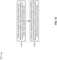
- Fig. 9 is a diagram illustrating an example process 900 performed, for example, by a wireless communication device, in accordance with various aspects of the present disclosure.
- Example process 900 is an example where a wireless communication device (e.g., base station 110, UE 120, TRP 508, transmitter 605, receiver 610, and/or the like) performs operations associated with transport block transmission using different spatial parameters.
- a wireless communication device e.g., base station 110, UE 120, TRP 508, transmitter 605, receiver 610, and/or the like
- performs operations associated with transport block transmission using different spatial parameters e.g., base station 110, UE 120, TRP 508, transmitter 605, receiver 610, and/or the like.
- process 900 may include determining a TB size of the TB based at least in part on the first set of parameters, the second set of parameters, or both the first set of parameters and the second set of parameters (block 920).
- the wireless communication device e.g., using controller/processor 240, controller/processor 280, and/or the like
- Process 900 may include additional aspects, such as any single aspect or any combination of aspects described below and/or in connection with one or more other processes described elsewhere herein.
- downlink control information indicates whether to use the first set of parameters, the second set of parameters, or both the first set of parameters and the second set of parameters to determine the TB size.
- the TB size is determined based at least in part on a function of a first TB size determined using the first set of parameters and a second TB size determined using the second set of parameters.
- the function includes: a minimum TB size of the first TB size and the second TB size, a maximum TB size of the first TB size and the second TB size, or an average TB size of the first TB size and the second TB size.
- the TB size is determined based at least in part on a single set of parameters, of the first set of parameters or the second set of parameters, corresponding to a single TB repetition, of the first TB repetition or the second TB repetition, associated with a pre-configured, pre-specified, or default spatial parameter.
- the TB size is determined based at least in part on a joint determination of the TB size that is a function of both the first set of parameters and the second set of parameters.
- the TB size is determined based at least in part on a rule that is commonly applied by a user equipment and a base station that transmit or receive the first TB repetition and the second TB repetition.
- the wireless communication device is one of a user equipment, a base station, or a transmit receive point.
- the first TB repetition and the second TB repetition are transmitted in one of a physical downlink shared channel or a physical uplink shared channel.
- the first set of parameters and the second set of parameters include at least one of: different respective first and second modulation and coding schemes, different respective first and second numbers of resource elements, different respective first and second numbers of layers, or a combination thereof.
- the different TTIs are different slots, different mini-slots, or different sets of symbols.
- the first set of parameters and the second set of parameters are indicated in at least one of: a radio resource control message, downlink control information, or a combination thereof.
- the first TB repetition and the second TB repetition are scheduled in different transmission time intervals.
- the first TB repetition and the second TB repetition are scheduled in different resource blocks.
- the first TB repetition and the second TB repetition are scheduled in different spatial layers.
- process 900 may include additional blocks, fewer blocks, different blocks, or differently arranged blocks than those depicted in Fig. 9 . Additionally, or alternatively, two or more of the blocks of process 900 may be performed in parallel.
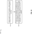
- Fig. 10 is a diagram illustrating an example process 1000 performed, for example, by a base station, in accordance with various aspects of the present disclosure.
- Example process 1000 is an example where a base station (e.g., base station 110, TRP 508, and/or the like) performs operations associated with transport block transmission using different spatial parameters.
- a base station e.g., base station 110, TRP 508, and/or the like
- process 1000 may include transmitting a grant for a first TB repetition, wherein the grant indicates a first mini-slot in which the first TB repetition is scheduled (block 1010).
- the base station e.g., using controller/processor 240, transmit processor 220, TX MIMO processor 230, MOD 232, antenna 234, and/or the like
- the grant indicates a first mini-slot in which the first TB repetition is scheduled.
- process 1000 may include scheduling one or more subsequent TB repetitions in one or more subsequent mini-slots that occur after the first mini-slot, wherein the one or more subsequent mini-slots are determined based at least in part on a mini-slot pattern configuration or one or more parameters of the first TB repetition (block 1020).
- the base station e.g., using controller/processor 240, scheduler 246, and/or the like
- the one or more subsequent mini-slots are determined based at least in part on a mini-slot pattern configuration or one or more parameters of the first TB repetition.
- Process 1000 may include additional aspects, such as any single aspect or any combination of aspects described below and/or in connection with one or more other processes described elsewhere herein.
- process 1000 includes transmitting the mini-slot pattern configuration that indicates a pattern of mini-slots, for a time period, associated with TB repetition.
- a set of parameters, indicated in the grant for the first TB repetition, are used for the one or more subsequent TB repetitions.
- the set of parameters includes at least one of: a modulation and coding scheme, a frequency domain allocation, a time domain allocation, a starting symbol of the first TB repetition, a length of the first TB repetition, or a combination thereof.
- process 1000 may include transmitting an indication of one or more spatial parameters or one or more redundancy versions corresponding to the one or more subsequent TB repetitions.
- the indication is transmitted in the grant or in a radio resource control (RRC) message.
- RRC radio resource control
- a TB size for the first TB repetition and the one or more subsequent TB repetitions is determined based at least in part on a set of parameters associated with the first TB repetition.
- the mini-slot pattern configuration indicates a respective set of symbols occupied by each mini-slot included in the pattern of mini-slots.
- the respective set of symbols is indicated by at least one of: a starting symbol and a number of symbols for the respective set of symbols, or a starting symbol and an ending symbol for the respective set of symbols.
- the time period is a number of symbols or a number of slots.
- the mini-slot pattern configuration is indicated in a radio resource control message.
- process 1000 includes: transmitting the first TB repetition, in the first mini-slot, and the one or more subsequent TB repetitions in the one or more subsequent mini-slots; or receiving the first TB repetition, in the first mini-slot, and the one or more subsequent TB repetitions in the one or more subsequent mini-slots.
- process 1000 may include additional blocks, fewer blocks, different blocks, or differently arranged blocks than those depicted in Fig. 10 . Additionally, or alternatively, two or more of the blocks of process 1000 may be performed in parallel.
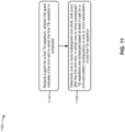
- Fig. 11 is a diagram illustrating an example process 1100 performed, for example, by a UE, in accordance with various aspects of the present disclosure.
- Example process 1100 is an example where a UE (e.g., UE 120 and/or the like) performs operations associated with transport block transmission using different spatial parameters.
- a UE e.g., UE 120 and/or the like
- process 1100 may include receiving a grant for a first TB repetition, wherein the grant indicates a first mini-slot in which the first TB repetition is scheduled (block 1110).
- the UE e.g., using antenna 252, DEMOD 254, MIMO detector 256, receive processor 258, controller/processor 280, and/or the like
- the grant indicates a first mini-slot in which the first TB repetition is scheduled.
- process 1100 may include determining one or more subsequent mini-slots, that occur after the first mini-slot, in which one or more subsequent TB repetitions are scheduled based at least in part on a mini-slot pattern configuration or one or more parameters of the first TB repetition (block 1120).
- the UE e.g., using controller/processor 280 and/or the like
- Process 1100 may include additional aspects, such as any single aspect or any combination of aspects described below and/or in connection with one or more other processes described elsewhere herein.
- process 1000 includes receiving the mini-slot pattern configuration that indicates a pattern of mini-slots, for a time period, associated with TB repetition.
- a set of parameters, indicated in the grant for the first TB repetition, are used for the one or more subsequent TB repetitions.
- the set of parameters includes at least one of: a modulation and coding scheme, a frequency domain allocation, a time domain allocation, a starting symbol of the first TB repetition, a length of the first TB repetition, or a combination thereof.
- process 1100 includes receiving an indication of one or more spatial parameters or one or more redundancy versions corresponding to the one or more subsequent TB repetitions.
- the indication is received in the grant or in a radio resource control (RRC) message.
- RRC radio resource control
- a TB size for the first TB repetition and the one or more subsequent TB repetitions is determined based at least in part on a set of parameters associated with the first TB repetition.
- the mini-slot pattern configuration indicates a respective set of symbols occupied by each mini-slot included in the pattern of mini-slots.
- the respective set of symbols is indicated by at least one of: a starting symbol and a number of symbols for the respective set of symbols, or a starting symbol and an ending symbol for the respective set of symbols.
- the time period is a number of symbols or a number of slots.
- the mini-slot pattern configuration is indicated in a radio resource control message.
- process 1100 includes: transmitting the first TB repetition, in the first mini-slot, and the one or more subsequent TB repetitions in the one or more subsequent mini-slots; or receiving the first TB repetition, in the first mini-slot, and the one or more subsequent TB repetitions in the one or more subsequent mini-slots.
- process 1100 may include additional blocks, fewer blocks, different blocks, or differently arranged blocks than those depicted in Fig. 11 . Additionally, or alternatively, two or more of the blocks of process 1100 may be performed in parallel.
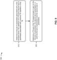
- Fig. 12 is a diagram illustrating an example process 1200 performed, for example, by a base station, in accordance with various aspects of the present disclosure.
- Example process 1200 is an example where a base station (e.g., base station 110, TRP 508, and/or the like) performs operations associated with transport block transmission using different spatial parameters.
- a base station e.g., base station 110, TRP 508, and/or the like
- process 1200 may include transmitting an indication of a first set of symbols and a second set of symbols in which a single communication is scheduled, wherein the single communication does not include multiple repetitions of a transport block (block 1210).
- the base station e.g., using controller/processor 240, transmit processor 220, TX MIMO processor 230, MOD 232, antenna 234, and/or the like
- the single communication does not include multiple repetitions of a transport block.
- process 1200 may include transmitting or receiving the single communication in the first set of symbols and the second set of symbols using a first spatial parameter for the first set of symbols and a second spatial parameter for the second set of symbols (block 1220).
- the base station e.g., using antenna 234, DEMOD 232, MIMO detector 236, receive processor 238, controller/processor 240, transmit processor 220, TX MIMO processor 230, MOD 232, and/or the like
- Process 1200 may include additional aspects, such as any single aspect or any combination of aspects described below and/or in connection with one or more other processes described elsewhere herein.
- the indication is an implicit indication based at least in part on a first symbol of a first demodulation reference signal (DMRS) and a second symbol of a second DMRS.
- DMRS demodulation reference signal
- the first symbol is a starting symbol of the first set of symbols and the second symbol is a starting symbol of the second set of symbols.
- the indication is an explicit indication indicated in downlink control information.
- downlink control information indicates the first spatial parameter and the second spatial parameter.
- the first set of symbols and the second set of symbols are contiguous.
- the first spatial parameter and the second spatial parameter are: respective first and second quasi co-location parameters, respective first and second transmission configuration indicator (TCI) states, respective first and second precoding parameters, respective first and second spatial domain filters, or a combination thereof.
- TCI transmission configuration indicator
- process 1200 may include additional blocks, fewer blocks, different blocks, or differently arranged blocks than those depicted in Fig. 12 . Additionally, or alternatively, two or more of the blocks of process 1200 may be performed in parallel.
- Fig. 13 is a diagram illustrating an example process 1300 performed, for example, by a UE, in accordance with various aspects of the present disclosure.
- Example process 1300 is an example where a UE (e.g., UE 120 and/or the like) performs operations associated with transport block transmission using different spatial parameters.
- a UE e.g., UE 120 and/or the like
- process 1300 may include receiving an indication of a first set of symbols and a second set of symbols in which a single communication is scheduled, wherein the single communication does not include multiple repetitions of a transport block (block 1310).
- the UE e.g., using antenna 252, DEMOD 254, MIMO detector 256, receive processor 258, controller/processor 280, and/or the like
- the single communication does not include multiple repetitions of a transport block.
- process 1300 may include transmitting or receiving the single communication in the first set of symbols and the second set of symbols using a first spatial parameter for the first set of symbols and a second spatial parameter for the second set of symbols (block 1320).
- the UE e.g., using antenna 252, DEMOD 254, MIMO detector 256, receive processor 258, controller/processor 280, transmit processor 264, TX MIMO processor 266, MOD 254, and/or the like
- Process 1300 may include additional aspects, such as any single aspect or any combination of aspects described below and/or in connection with one or more other processes described elsewhere herein.
- the indication is an implicit indication based at least in part on a first symbol of a first demodulation reference signal (DMRS) and a second symbol of a second DMRS.
- DMRS demodulation reference signal
- the first symbol is a starting symbol of the first set of symbols and the second symbol is a starting symbol of the second set of symbols.
- the indication is an explicit indication indicated in downlink control information.
- downlink control information indicates the first spatial parameter and the second spatial parameter.
- the first set of symbols and the second set of symbols are contiguous.
- the first spatial parameter and the second spatial parameter are: respective first and second quasi co-location parameters, respective first and second transmission configuration indicator (TCI) states, respective first and second precoding parameters, respective first and second spatial domain filters, or a combination thereof.
- TCI transmission configuration indicator
- process 1300 may include additional blocks, fewer blocks, different blocks, or differently arranged blocks than those depicted in Fig. 13 . Additionally, or alternatively, two or more of the blocks of process 1300 may be performed in parallel.
- ком ⁇ онент is intended to be broadly construed as hardware, firmware, or a combination of hardware and software.
- a processor is implemented in hardware, firmware, or a combination of hardware and software.
- satisfying a threshold may refer to a value being greater than the threshold, greater than or equal to the threshold, less than the threshold, less than or equal to the threshold, equal to the threshold, not equal to the threshold, and/or the like.
Landscapes
- Engineering & Computer Science (AREA)
- Signal Processing (AREA)
- Computer Networks & Wireless Communication (AREA)
- Quality & Reliability (AREA)
- Mobile Radio Communication Systems (AREA)
Claims (9)
- Ein Verfahren (900) für eine drahtlose Kommunikation, das durch ein erstes drahtloses Kommunikationsgerät durchgeführt wird, wobei das Verfahren (900) aufweist:
Bestimmen (910) eines ersten Satzes von Transportblock (TB)-Größe-Bestimmungsparametern, die mit einer ersten TB-Wiederholung eines TB assoziiert sind, und eines zweiten Satzes von TB-Größe-Bestimmungsparametern, die mit einer zweiten TB-Wiederholung des TB assoziiert sind, wobei:
der erste Satz von TB-Größe-Bestimmungsparametern und der zweite Satz von TB-Größe-Bestimmungsparametern wenigstens eines der Folgenden aufweisen:jeweils verschiedene erste und zweite Modulations- und Codierschemata für das TB,jeweils verschiedene erste und zweite Anzahlen von Ressourcenelementen (REs), die für den TB zugewiesen sind,jeweils verschiedene erste und zweite Anzahlen von Schichten für das Senden des TB, odereine Kombination aus diesen, wobei eine erste TB-Wiederholungsgröße basierend auf dem ersten Satz von TB-Größe-Bestimmungsparametern von einer zweiten TB-Wiederholungsgröße basierend auf dem zweiten Satz von TB-Größe-Bestimmungsparametern, zumeist verschieden ist, wenn diese unabhängig voneinander bestimmt werden,wobei das Verfahren weiterhin aufweist:Empfangen, von einem zweiten drahtlosen Kommunikationsgerät, einer Regel, die angibt, wie die TB-Größe für alle TB-Wiederholungen zu bestimmen ist, wobei die Regel eine allgemeine Regel ist, die durch das erste drahtlose Kommunikationsgerät und das zweite drahtlose Kommunikationsgerät angewendet wird, wobei eine Anwendung der Regel in einer für alle TB-Wiederholungen zu verwendenden gleichen TB-Größe resultiert,Berechnen einer ersten TB-Größe unter Verwendung des ersten Satzes von TB-Größe-Bestimmungsparametern und einer zweiten TB-Größe unter Verwendung des zweiten Satzes von TB-Größe-Bestimmungsparametern,Anwenden einer Funktion auf die berechnete erste TB-Größe und die berechnete zweite TB-Größe, um die für alle TB-Wiederholungen zu verwendende gleiche TB-Größe zu bestimmen, wobei die Funktion die minimale TB-Größe der berechneten TB-Größen, die maximale TB-Größe der berechneten TB-Größen oder die durchschnittliche TB-Größe der TB-Größen ist, undKommunizieren, mit dem zweiten drahtlosen Kommunikationsgerät, der ersten TB-Wiederholung und der zweiten TB-Wiederholung unter Verwendung der gleichen TB-Größe. - Verfahren nach Anspruch 1, wobei die erste TB-Wiederholung und die zweite TB-Wiederholung in verschiedenen Sendezeitintervallen geplant werden.
- Verfahren nach Anspruch 2, wobei die verschiedenen Sendezeitintervalle verschiedene Schlitze, verschiedene Minischlitze oder verschiedene Sätze von Symbolen sind.
- Verfahren nach Anspruch 1, wobei die erste TB-Wiederholung und die zweite TB-Wiederholung in verschiedenen Ressourcenblöcken geplant werden.
- Verfahren nach Anspruch 1, wobei die erste TB-Wiederholung und die zweite TB-Wiederholung in verschiedenen Raumschichten geplant werden.
- Verfahren nach Anspruch 1, wobei das drahtlose Kommunikationsgerät ein Benutzergerät, eine Basisstation oder ein Sendeempfangspunkt ist.
- Verfahren nach Anspruch 1, wobei der erste Satz von Parametern und der zweite Satz von Parametern in wenigstens einem der Folgenden angegeben werden:einer Funkressourcensteuerungsnachricht,Abwärtsstrecke-Steuerinformationen, odereiner Kombination aus diesen.
- Ein drahtloses Kommunikationsgerät, das Mittel zum Durchführen des Verfahrens gemäß einem der Ansprüche 1 bis 7 aufweist.
- Ein computerlesbares Medium, das Befehle aufweist, die bei einer Ausführung durch einen Computer den Computer zum Durchführen des Verfahrens gemäß einem der Ansprüche 1 bis 7 veranlassen.
Priority Applications (1)
| Application Number | Priority Date | Filing Date | Title |
|---|---|---|---|
| EP24197254.6A EP4447352A3 (de) | 2018-10-31 | 2019-10-11 | Transportblockübertragungswiederholung unter verwendung verschiedener räumlicher parameter |
Applications Claiming Priority (3)
| Application Number | Priority Date | Filing Date | Title |
|---|---|---|---|
| US201862753517P | 2018-10-31 | 2018-10-31 | |
| US16/598,996 US11831571B2 (en) | 2018-10-31 | 2019-10-10 | Transport block transmission using different spatial parameters |
| PCT/US2019/055838 WO2020091973A1 (en) | 2018-10-31 | 2019-10-11 | Transport block transmission repetition using different spatial parameters |
Related Child Applications (2)
| Application Number | Title | Priority Date | Filing Date |
|---|---|---|---|
| EP24197254.6A Division EP4447352A3 (de) | 2018-10-31 | 2019-10-11 | Transportblockübertragungswiederholung unter verwendung verschiedener räumlicher parameter |
| EP24197254.6A Division-Into EP4447352A3 (de) | 2018-10-31 | 2019-10-11 | Transportblockübertragungswiederholung unter verwendung verschiedener räumlicher parameter |
Publications (3)
| Publication Number | Publication Date |
|---|---|
| EP3874639A1 EP3874639A1 (de) | 2021-09-08 |
| EP3874639C0 EP3874639C0 (de) | 2024-10-02 |
| EP3874639B1 true EP3874639B1 (de) | 2024-10-02 |
Family
ID=70325876
Family Applications (2)
| Application Number | Title | Priority Date | Filing Date |
|---|---|---|---|
| EP24197254.6A Pending EP4447352A3 (de) | 2018-10-31 | 2019-10-11 | Transportblockübertragungswiederholung unter verwendung verschiedener räumlicher parameter |
| EP19797458.7A Active EP3874639B1 (de) | 2018-10-31 | 2019-10-11 | Transportblockübertragungswiederholung unter verwendung verschiedener räumlicher parameter |
Family Applications Before (1)
| Application Number | Title | Priority Date | Filing Date |
|---|---|---|---|
| EP24197254.6A Pending EP4447352A3 (de) | 2018-10-31 | 2019-10-11 | Transportblockübertragungswiederholung unter verwendung verschiedener räumlicher parameter |
Country Status (4)
| Country | Link |
|---|---|
| US (3) | US11831571B2 (de) |
| EP (2) | EP4447352A3 (de) |
| CN (2) | CN112889231B (de) |
| WO (1) | WO2020091973A1 (de) |
Families Citing this family (15)
| Publication number | Priority date | Publication date | Assignee | Title |
|---|---|---|---|---|
| EP3785388B1 (de) * | 2018-04-23 | 2023-07-12 | Telefonaktiebolaget LM Ericsson (publ.) | Zeitbereichszuordnung für wiederholungen |
| US11831571B2 (en) | 2018-10-31 | 2023-11-28 | Qualcomm Incorporated | Transport block transmission using different spatial parameters |
| WO2020133036A1 (zh) * | 2018-12-27 | 2020-07-02 | Oppo广东移动通信有限公司 | 重复传输方法、装置、芯片及计算机程序 |
| WO2020192481A1 (zh) * | 2019-03-28 | 2020-10-01 | 华为技术有限公司 | 通信方法和装置 |
| WO2020222290A1 (en) * | 2019-05-02 | 2020-11-05 | Sharp Kabushiki Kaisha | User equipments, base stations and methods for transport block determination for mini-slot pusch |
| EP4026364A4 (de) * | 2019-09-02 | 2022-08-17 | Telefonaktiebolaget LM Ericsson (publ) | Verbesserte spektrumsnutzung in einem drahtlosen kommunikationsnetz |
| CN111342938B (zh) * | 2019-12-31 | 2024-08-09 | 中兴通讯股份有限公司 | 物理信道传输方法、装置、节点和存储介质 |
| US20230246778A1 (en) * | 2020-05-13 | 2023-08-03 | Qualcomm Incorporated | Demodulation reference signal enhancements for control channel repetitions |
| CA3180911A1 (en) * | 2020-06-04 | 2021-12-09 | Ankit Bhamri | Time-domain repetition of a set of transport blocks |
| WO2022067867A1 (en) | 2020-10-03 | 2022-04-07 | Qualcomm Incorporated | Time gaps between physical uplink shared channel repetitions |
| US20220272725A1 (en) * | 2021-02-19 | 2022-08-25 | Qualcomm Incorporated | Dynamic indication of single-transport block (tb) transmission vs multiple-tb repetition |
| US12273206B2 (en) * | 2021-05-11 | 2025-04-08 | Qualcomm Incorporated | Parameter configuration for configured grant based multi-transmission reception point communications |
| WO2023092275A1 (en) * | 2021-11-23 | 2023-06-01 | Qualcomm Incorporated | Harq codebook and feedback for multi-pdsch repetitions |
| US12191991B2 (en) * | 2022-01-06 | 2025-01-07 | Qualcomm Incorporated | Self-decodable data portion for physical uplink repetition |
| CN118805415A (zh) * | 2022-03-01 | 2024-10-18 | 苹果公司 | 利用统一tci框架的上行链路波束指示 |
Citations (2)
| Publication number | Priority date | Publication date | Assignee | Title |
|---|---|---|---|---|
| US7289574B2 (en) * | 2001-04-30 | 2007-10-30 | Sergio Parolari | Method of link adaptation in enhanced cellular systems to discriminate between high and low variability |
| US20130094468A1 (en) * | 2010-06-22 | 2013-04-18 | Lg Electronics Inc. | Method and device for determining precoding information for uplink multi-antenna transmission |
Family Cites Families (24)
| Publication number | Priority date | Publication date | Assignee | Title |
|---|---|---|---|---|
| US9154352B2 (en) * | 2009-04-21 | 2015-10-06 | Qualcomm Incorporated | Pre-communication for relay base stations in wireless communication |
| WO2016119232A1 (en) | 2015-01-30 | 2016-08-04 | Mediatek Singapore Pte. Ltd. | Methods for determination of repetition number of physical data channel |
| US10966194B2 (en) | 2015-04-15 | 2021-03-30 | Qualcomm Incorporated | Coordinated wireless communications using multiple transmission time intervals |
| US10485003B2 (en) * | 2015-05-14 | 2019-11-19 | Nokia Technologies Oy | Method, apparatus and computer program product for determining transmission parameters |
| CN106961318B (zh) * | 2016-01-11 | 2020-07-10 | 中兴通讯股份有限公司 | 一种确定编码调制参数的方法、装置和系统 |
| CN107040487B (zh) | 2016-02-04 | 2021-06-15 | 中兴通讯股份有限公司 | 信号处理方法及装置 |
| CN108631910B (zh) | 2017-03-22 | 2021-10-19 | 华为技术有限公司 | 一种数据传输方法及装置 |
| US10965402B2 (en) * | 2017-03-23 | 2021-03-30 | Telefonaktiebolaget Lm Ericsson (Publ) | Configuring puncture bundles of data for a first service in a transmission of a second service |
| JP2019036777A (ja) * | 2017-08-10 | 2019-03-07 | シャープ株式会社 | 基地局装置および端末装置 |
| GB2565348B (en) * | 2017-08-11 | 2022-05-18 | Tcl Communication Ltd | Slot bundling |
| EP3692660A1 (de) * | 2017-10-02 | 2020-08-12 | Telefonaktiebolaget LM Ericsson (Publ) | Prb-bündelungserweiterung |
| US10708912B2 (en) * | 2017-11-13 | 2020-07-07 | Asustek Computer Inc. | Method and apparatus for indicating time domain resource allocation of data transmission in a wireless communication system |
| US10904909B2 (en) * | 2018-01-23 | 2021-01-26 | Huawei Technologies Co., Ltd. | System and method for time domain grant-free PUSCH resource allocation |
| CN112219364A (zh) * | 2018-04-05 | 2021-01-12 | 株式会社Ntt都科摩 | 发送装置以及接收装置 |
| US11229047B2 (en) * | 2018-04-06 | 2022-01-18 | Qualcomm Incorporated | Transport block repetition handling for downlink and uplink transmissions |
| US11044748B2 (en) | 2018-05-01 | 2021-06-22 | Huawei Technologies Co., Ltd. | Methods and apparatus for sidelink communications and resource allocation |
| CN110474726A (zh) * | 2018-05-10 | 2019-11-19 | 夏普株式会社 | 由用户设备执行的方法以及用户设备 |
| US10701679B2 (en) * | 2018-07-05 | 2020-06-30 | Huawei Technologies Co., Ltd. | Method and system for enhancing data channel reliability using multiple transmit receive points |
| EP3609104A1 (de) * | 2018-08-09 | 2020-02-12 | Panasonic Intellectual Property Corporation of America | Flexible wiederholung von pusch-mini-slots innerhalb eines slots |
| US11791951B2 (en) * | 2018-08-09 | 2023-10-17 | Huawei Technologies Co., Ltd. | Mini-slot based repetition and frequency hopping |
| JP6926043B2 (ja) * | 2018-09-20 | 2021-08-25 | シャープ株式会社 | 端末装置、基地局装置およびその通信方法 |
| CN110943805B (zh) * | 2018-09-21 | 2021-06-04 | 电信科学技术研究院有限公司 | 一种harq-ack的传输方法、终端设备及网络设备 |
| US11050525B2 (en) * | 2018-09-27 | 2021-06-29 | Huawei Technologies Co., Ltd. | System and method for control and data channel reliability enhancement using multiple diversity domains |
| US11831571B2 (en) | 2018-10-31 | 2023-11-28 | Qualcomm Incorporated | Transport block transmission using different spatial parameters |
-
2019
- 2019-10-10 US US16/598,996 patent/US11831571B2/en active Active
- 2019-10-11 CN CN201980070265.XA patent/CN112889231B/zh active Active
- 2019-10-11 CN CN202410414326.2A patent/CN118074866A/zh active Pending
- 2019-10-11 WO PCT/US2019/055838 patent/WO2020091973A1/en not_active Ceased
- 2019-10-11 EP EP24197254.6A patent/EP4447352A3/de active Pending
- 2019-10-11 EP EP19797458.7A patent/EP3874639B1/de active Active
-
2023
- 2023-10-13 US US18/486,990 patent/US12381670B2/en active Active
-
2025
- 2025-07-15 US US19/269,807 patent/US20250343644A1/en active Pending
Patent Citations (2)
| Publication number | Priority date | Publication date | Assignee | Title |
|---|---|---|---|---|
| US7289574B2 (en) * | 2001-04-30 | 2007-10-30 | Sergio Parolari | Method of link adaptation in enhanced cellular systems to discriminate between high and low variability |
| US20130094468A1 (en) * | 2010-06-22 | 2013-04-18 | Lg Electronics Inc. | Method and device for determining precoding information for uplink multi-antenna transmission |
Non-Patent Citations (1)
| Title |
|---|
| HUAWEI ET AL: "Preventing UL HARQ transmissions without MCS information", 3GPP DRAFT; R2-084371 PREVENTING UL HARQ TRANSMISSIONS WITHOUT MCS INFORMATION, 3RD GENERATION PARTNERSHIP PROJECT (3GPP), MOBILE COMPETENCE CENTRE ; 650, ROUTE DES LUCIOLES ; F-06921 SOPHIA-ANTIPOLIS CEDEX ; FRANCE, vol. RAN WG2, no. Jeju, Korea; 20080818 - 20080822, 12 August 2008 (2008-08-12), XP050603979 * |
Also Published As
| Publication number | Publication date |
|---|---|
| US12381670B2 (en) | 2025-08-05 |
| WO2020091973A1 (en) | 2020-05-07 |
| CN112889231B (zh) | 2024-04-26 |
| US20250343644A1 (en) | 2025-11-06 |
| US11831571B2 (en) | 2023-11-28 |
| CN118074866A (zh) | 2024-05-24 |
| US20240048301A1 (en) | 2024-02-08 |
| EP3874639A1 (de) | 2021-09-08 |
| CN112889231A (zh) | 2021-06-01 |
| EP3874639C0 (de) | 2024-10-02 |
| EP4447352A2 (de) | 2024-10-16 |
| US20200136770A1 (en) | 2020-04-30 |
| EP4447352A3 (de) | 2024-12-11 |
Similar Documents
| Publication | Publication Date | Title |
|---|---|---|
| US12381670B2 (en) | Transport block transmission using different spatial parameters | |
| US11337195B2 (en) | Selectively multiplexing physical uplink shared channel (PUSCH) and physical uplink control channel (PUCCH) communications | |
| EP3824584B1 (de) | Steuerkanalwiederholung einer physikalischen aufwärtsstrecke | |
| EP3857957B1 (de) | Sendeparameterregelung | |
| AU2019221649B2 (en) | Physical resource block bundle size selection | |
| US11849456B2 (en) | Construction and mapping of compact uplink control information (UCI) over physical uplink shared channel (PUSCH) | |
| US11395270B2 (en) | Uplink control information payload size | |
| WO2020102502A1 (en) | Scheduling timelines for multi-transmit receive point operations | |
| EP3777334B1 (de) | Übertragung von daten in einem steuerkanal | |
| EP3963774A1 (de) | Harq-rückkopplung für sidelink-kommunikation | |
| US11758478B2 (en) | Power saving based on a combined timing indication and search space set group indication | |
| EP3963957A1 (de) | Mehrbenutzer-aufwecksignal | |
| EP4038782A1 (de) | Physikalisches uplink-steuerungskanalformat für einen einzigen uplink-betrieb im doppelverbindungsmodus mit zeitduplex-primärzelle | |
| EP3811712B1 (de) | Kollisionsverwaltung | |
| KR102765777B1 (ko) | 짧은 송신 시간 간격(sTTI) 시스템을 위한 자원 할당 | |
| EP3959929B1 (de) | Verstärkung von zellerfassungssubframes für zellulare rundfunkdienste |
Legal Events
| Date | Code | Title | Description |
|---|---|---|---|
| STAA | Information on the status of an ep patent application or granted ep patent |
Free format text: STATUS: UNKNOWN |
|
| STAA | Information on the status of an ep patent application or granted ep patent |
Free format text: STATUS: THE INTERNATIONAL PUBLICATION HAS BEEN MADE |
|
| PUAI | Public reference made under article 153(3) epc to a published international application that has entered the european phase |
Free format text: ORIGINAL CODE: 0009012 |
|
| STAA | Information on the status of an ep patent application or granted ep patent |
Free format text: STATUS: REQUEST FOR EXAMINATION WAS MADE |
|
| 17P | Request for examination filed |
Effective date: 20210330 |
|
| AK | Designated contracting states |
Kind code of ref document: A1 Designated state(s): AL AT BE BG CH CY CZ DE DK EE ES FI FR GB GR HR HU IE IS IT LI LT LU LV MC MK MT NL NO PL PT RO RS SE SI SK SM TR |
|
| DAV | Request for validation of the european patent (deleted) | ||
| DAX | Request for extension of the european patent (deleted) | ||
| STAA | Information on the status of an ep patent application or granted ep patent |
Free format text: STATUS: EXAMINATION IS IN PROGRESS |
|
| 17Q | First examination report despatched |
Effective date: 20230102 |
|
| GRAP | Despatch of communication of intention to grant a patent |
Free format text: ORIGINAL CODE: EPIDOSNIGR1 |
|
| STAA | Information on the status of an ep patent application or granted ep patent |
Free format text: STATUS: GRANT OF PATENT IS INTENDED |
|
| INTG | Intention to grant announced |
Effective date: 20240423 |
|
| GRAS | Grant fee paid |
Free format text: ORIGINAL CODE: EPIDOSNIGR3 |
|
| GRAA | (expected) grant |
Free format text: ORIGINAL CODE: 0009210 |
|
| STAA | Information on the status of an ep patent application or granted ep patent |
Free format text: STATUS: THE PATENT HAS BEEN GRANTED |
|
| AK | Designated contracting states |
Kind code of ref document: B1 Designated state(s): AL AT BE BG CH CY CZ DE DK EE ES FI FR GB GR HR HU IE IS IT LI LT LU LV MC MK MT NL NO PL PT RO RS SE SI SK SM TR |
|
| REG | Reference to a national code |
Ref country code: GB Ref legal event code: FG4D |
|
| REG | Reference to a national code |
Ref country code: CH Ref legal event code: EP |
|
| REG | Reference to a national code |
Ref country code: IE Ref legal event code: FG4D |
|
| REG | Reference to a national code |
Ref country code: DE Ref legal event code: R096 Ref document number: 602019059768 Country of ref document: DE |
|
| U01 | Request for unitary effect filed |
Effective date: 20241015 |
|
| U07 | Unitary effect registered |
Designated state(s): AT BE BG DE DK EE FI FR IT LT LU LV MT NL PT RO SE SI Effective date: 20241031 |
|
| U20 | Renewal fee for the european patent with unitary effect paid |
Year of fee payment: 6 Effective date: 20250128 |
|
| PG25 | Lapsed in a contracting state [announced via postgrant information from national office to epo] |
Ref country code: IS Free format text: LAPSE BECAUSE OF FAILURE TO SUBMIT A TRANSLATION OF THE DESCRIPTION OR TO PAY THE FEE WITHIN THE PRESCRIBED TIME-LIMIT Effective date: 20250202 Ref country code: HR Free format text: LAPSE BECAUSE OF FAILURE TO SUBMIT A TRANSLATION OF THE DESCRIPTION OR TO PAY THE FEE WITHIN THE PRESCRIBED TIME-LIMIT Effective date: 20241002 |
|
| PG25 | Lapsed in a contracting state [announced via postgrant information from national office to epo] |
Ref country code: ES Free format text: LAPSE BECAUSE OF FAILURE TO SUBMIT A TRANSLATION OF THE DESCRIPTION OR TO PAY THE FEE WITHIN THE PRESCRIBED TIME-LIMIT Effective date: 20241002 |
|
| PG25 | Lapsed in a contracting state [announced via postgrant information from national office to epo] |
Ref country code: NO Free format text: LAPSE BECAUSE OF FAILURE TO SUBMIT A TRANSLATION OF THE DESCRIPTION OR TO PAY THE FEE WITHIN THE PRESCRIBED TIME-LIMIT Effective date: 20250102 |
|
| PG25 | Lapsed in a contracting state [announced via postgrant information from national office to epo] |
Ref country code: GR Free format text: LAPSE BECAUSE OF FAILURE TO SUBMIT A TRANSLATION OF THE DESCRIPTION OR TO PAY THE FEE WITHIN THE PRESCRIBED TIME-LIMIT Effective date: 20250103 |
|
| PG25 | Lapsed in a contracting state [announced via postgrant information from national office to epo] |
Ref country code: PL Free format text: LAPSE BECAUSE OF FAILURE TO SUBMIT A TRANSLATION OF THE DESCRIPTION OR TO PAY THE FEE WITHIN THE PRESCRIBED TIME-LIMIT Effective date: 20241002 Ref country code: CZ Free format text: LAPSE BECAUSE OF FAILURE TO SUBMIT A TRANSLATION OF THE DESCRIPTION OR TO PAY THE FEE WITHIN THE PRESCRIBED TIME-LIMIT Effective date: 20241002 |
|
| PG25 | Lapsed in a contracting state [announced via postgrant information from national office to epo] |
Ref country code: RS Free format text: LAPSE BECAUSE OF FAILURE TO SUBMIT A TRANSLATION OF THE DESCRIPTION OR TO PAY THE FEE WITHIN THE PRESCRIBED TIME-LIMIT Effective date: 20250102 |
|
| REG | Reference to a national code |
Ref country code: CH Ref legal event code: PL |
|
| PG25 | Lapsed in a contracting state [announced via postgrant information from national office to epo] |
Ref country code: SM Free format text: LAPSE BECAUSE OF FAILURE TO SUBMIT A TRANSLATION OF THE DESCRIPTION OR TO PAY THE FEE WITHIN THE PRESCRIBED TIME-LIMIT Effective date: 20241002 |
|
| PG25 | Lapsed in a contracting state [announced via postgrant information from national office to epo] |
Ref country code: MC Free format text: LAPSE BECAUSE OF FAILURE TO SUBMIT A TRANSLATION OF THE DESCRIPTION OR TO PAY THE FEE WITHIN THE PRESCRIBED TIME-LIMIT Effective date: 20241002 |
|
| PG25 | Lapsed in a contracting state [announced via postgrant information from national office to epo] |
Ref country code: CH Free format text: LAPSE BECAUSE OF NON-PAYMENT OF DUE FEES Effective date: 20241031 |
|
| PG25 | Lapsed in a contracting state [announced via postgrant information from national office to epo] |
Ref country code: SK Free format text: LAPSE BECAUSE OF FAILURE TO SUBMIT A TRANSLATION OF THE DESCRIPTION OR TO PAY THE FEE WITHIN THE PRESCRIBED TIME-LIMIT Effective date: 20241002 |
|
| PLBE | No opposition filed within time limit |
Free format text: ORIGINAL CODE: 0009261 |
|
| STAA | Information on the status of an ep patent application or granted ep patent |
Free format text: STATUS: NO OPPOSITION FILED WITHIN TIME LIMIT |
|
| 26N | No opposition filed |
Effective date: 20250703 |
|
| PGFP | Annual fee paid to national office [announced via postgrant information from national office to epo] |
Ref country code: GB Payment date: 20250911 Year of fee payment: 7 |
|
| PGFP | Annual fee paid to national office [announced via postgrant information from national office to epo] |
Ref country code: IE Payment date: 20250912 Year of fee payment: 7 |
|
| U20 | Renewal fee for the european patent with unitary effect paid |
Year of fee payment: 7 Effective date: 20250915 |
|
| PG25 | Lapsed in a contracting state [announced via postgrant information from national office to epo] |
Ref country code: CY Free format text: LAPSE BECAUSE OF FAILURE TO SUBMIT A TRANSLATION OF THE DESCRIPTION OR TO PAY THE FEE WITHIN THE PRESCRIBED TIME-LIMIT; INVALID AB INITIO Effective date: 20191011 |