EP4147100B1 - Werkzeugteil, system, verfahren und computerprogramm zur bestimmung einer abmessung des werkzeugteils - Google Patents
Werkzeugteil, system, verfahren und computerprogramm zur bestimmung einer abmessung des werkzeugteils Download PDFInfo
- Publication number
- EP4147100B1 EP4147100B1 EP21720496.5A EP21720496A EP4147100B1 EP 4147100 B1 EP4147100 B1 EP 4147100B1 EP 21720496 A EP21720496 A EP 21720496A EP 4147100 B1 EP4147100 B1 EP 4147100B1
- Authority
- EP
- European Patent Office
- Prior art keywords
- tool part
- machine
- information data
- dimension
- dimension information
- Prior art date
- Legal status (The legal status is an assumption and is not a legal conclusion. Google has not performed a legal analysis and makes no representation as to the accuracy of the status listed.)
- Active
Links
Images

Classifications
-
- G—PHYSICS
- G05—CONTROLLING; REGULATING
- G05B—CONTROL OR REGULATING SYSTEMS IN GENERAL; FUNCTIONAL ELEMENTS OF SUCH SYSTEMS; MONITORING OR TESTING ARRANGEMENTS FOR SUCH SYSTEMS OR ELEMENTS
- G05B19/00—Programme-control systems
- G05B19/02—Programme-control systems electric
- G05B19/04—Programme control other than numerical control, i.e. in sequence controllers or logic controllers
- G05B19/12—Programme control other than numerical control, i.e. in sequence controllers or logic controllers using record carriers
- G05B19/128—Programme control other than numerical control, i.e. in sequence controllers or logic controllers using record carriers the workpiece itself serves as a record carrier, e.g. by its form, by marks or codes on it
-
- G—PHYSICS
- G05—CONTROLLING; REGULATING
- G05B—CONTROL OR REGULATING SYSTEMS IN GENERAL; FUNCTIONAL ELEMENTS OF SUCH SYSTEMS; MONITORING OR TESTING ARRANGEMENTS FOR SUCH SYSTEMS OR ELEMENTS
- G05B19/00—Programme-control systems
- G05B19/02—Programme-control systems electric
- G05B19/18—Numerical control [NC], i.e. automatically operating machines, in particular machine tools, e.g. in a manufacturing environment, so as to execute positioning, movement or co-ordinated operations by means of programme data in numerical form
- G05B19/406—Numerical control [NC], i.e. automatically operating machines, in particular machine tools, e.g. in a manufacturing environment, so as to execute positioning, movement or co-ordinated operations by means of programme data in numerical form characterised by monitoring or safety
- G05B19/4065—Monitoring tool breakage, life or condition
-
- G—PHYSICS
- G06—COMPUTING OR CALCULATING; COUNTING
- G06K—GRAPHICAL DATA READING; PRESENTATION OF DATA; RECORD CARRIERS; HANDLING RECORD CARRIERS
- G06K7/00—Methods or arrangements for sensing record carriers, e.g. for reading patterns
- G06K7/10—Methods or arrangements for sensing record carriers, e.g. for reading patterns by electromagnetic radiation, e.g. optical sensing; by corpuscular radiation
- G06K7/10009—Methods or arrangements for sensing record carriers, e.g. for reading patterns by electromagnetic radiation, e.g. optical sensing; by corpuscular radiation sensing by radiation using wavelengths larger than 0.1 mm, e.g. radio-waves or microwaves
- G06K7/10366—Methods or arrangements for sensing record carriers, e.g. for reading patterns by electromagnetic radiation, e.g. optical sensing; by corpuscular radiation sensing by radiation using wavelengths larger than 0.1 mm, e.g. radio-waves or microwaves the interrogation device being adapted for miscellaneous applications
-
- G—PHYSICS
- G05—CONTROLLING; REGULATING
- G05B—CONTROL OR REGULATING SYSTEMS IN GENERAL; FUNCTIONAL ELEMENTS OF SUCH SYSTEMS; MONITORING OR TESTING ARRANGEMENTS FOR SUCH SYSTEMS OR ELEMENTS
- G05B2219/00—Program-control systems
- G05B2219/20—Pc systems
- G05B2219/25—Pc structure of the system
- G05B2219/25294—Part, workpiece, code, tool identification
-
- G—PHYSICS
- G05—CONTROLLING; REGULATING
- G05B—CONTROL OR REGULATING SYSTEMS IN GENERAL; FUNCTIONAL ELEMENTS OF SUCH SYSTEMS; MONITORING OR TESTING ARRANGEMENTS FOR SUCH SYSTEMS OR ELEMENTS
- G05B2219/00—Program-control systems
- G05B2219/30—Nc systems
- G05B2219/32—Operator till task planning
- G05B2219/32049—Store program data, manufacturing history on workpiece, shifts to next
-
- Y—GENERAL TAGGING OF NEW TECHNOLOGICAL DEVELOPMENTS; GENERAL TAGGING OF CROSS-SECTIONAL TECHNOLOGIES SPANNING OVER SEVERAL SECTIONS OF THE IPC; TECHNICAL SUBJECTS COVERED BY FORMER USPC CROSS-REFERENCE ART COLLECTIONS [XRACs] AND DIGESTS
- Y02—TECHNOLOGIES OR APPLICATIONS FOR MITIGATION OR ADAPTATION AGAINST CLIMATE CHANGE
- Y02P—CLIMATE CHANGE MITIGATION TECHNOLOGIES IN THE PRODUCTION OR PROCESSING OF GOODS
- Y02P90/00—Enabling technologies with a potential contribution to greenhouse gas [GHG] emissions mitigation
- Y02P90/02—Total factory control, e.g. smart factories, flexible manufacturing systems [FMS] or integrated manufacturing systems [IMS]
Definitions
- the present disclosure relates to a tool part, system, method, and a computer program product for utilizing an identification marker on a tool part for determining a dimension of the tool part.
- machine operations are operations by machines with cutting tools that are configured to remove chips from a piece of material during the machine operation by the cutting tool.
- the machine for cutting may require plural tool parts to be located at desired locations before starting the machine operation with the cutting tool parts.
- a cutting tool may comprise plural tool parts, e.g. a certain tool holder with one or more certain cutting inserts attached at the tool holder.
- the cutting inserts may have plural cutting edges, and therefore each cutting insert may need to be arranged at the tool holder at a certain location e.g. so that a correct distance from the piece of material to the cutting edge is used during the machine operation by the cutting tool.
- an operator of a machine needs to locate the tool part and verify that the tool part is at a desired location before the machine operation can start.
- the operator of a cutting machine therefore needs to verify that e.g. the cutting edge of a cutting insert is at a desired location. This is often done by visual inspection and sometimes by manual measurements by the operator of the machine, before the machine operation can be started by the operator.
- a first drawback of current approaches is that a cutting tool can be erroneously positioned and therefore located at an undesirable location so that an incorrect distance from the piece of material to the cutting edge of the cutting tool is used during the machine operation with the cutting tool, which in turn may cause severe damage to both the cutting tool but also to the piece of material.
- a second drawback of current approaches is that even if the operator verifies that the tool part is located at a desirable location before the machine operation, the human error factor is one factor that can lead to an erroneously positioning of a tool part in a machine operation.
- a third drawback of the current approaches is that a lot of time is spent on localizing a tool part in relation to e.g. a machine and/or a material to be processed by the tool part when the tool part is attached to the machine. This time is costly and adds time to total manufacturing process of a product.
- Document JP 2020 044643 A discloses a cutting insert attached to a tool main portion, that has identification code which identifies a cutting insert.
- Document EP 2 296 102 A1 discloses a device for reading two-dimensional code formed in circular-shaped element e.g. steel pipe, has illumination unit that is arranged to satisfy preset formula for irradiating inclination portion.
- a dimension of a specific tool part can be documented as a dimension value +/- a certain tolerance value. Often when manufacturing a specific tool part, the manufacturing process itself cannot be that precise, and therefore each manufactured tool part will have a true dimension that is within a certain tolerance, i.e. within the certain tolerance value, of the desired dimension value.
- This documented dimension can hence be used to some extent, but still the tolerance value will have to be measured for each individual tool part before the individual tool part is used e.g. in a machine operation. This means that time needs to be spent on e.g. verifying the exact dimension of the individual tool part.
- the tool part can be e.g. a cutting insert, a cutting edge, a milling tool part, a drilling tool part, a drill chuck, a milling cutter chuck or a tool holder.
- the inventors have come up with a solution that decreases the risk of human errors and that can also reduce the time needed for verifying that a desired tool part is located at a desired location in relation to e.g. a machine and/or a material.
- aspects and embodiments will be presented where alternative approaches for decreasing the risk of human errors and localizing a tool part in relation to e.g. a machine and/or a material are described.
- Example tool parts for use in a machine operation will now be described for illustrative purpose, to visualize and exemplify the prior art and the aspects of the disclosure. It is understood that the aspects of the disclosure can be applied to any tool part in any machine operation.
- Example machine operations are related to machines with cutting tools that are used to remove chips from a piece of material during the machine operation.
- Piece of material as described herein, may typically comprise a work piece of metal to be processed, but the material may be any other material such as a plastic, stone or wood material.
- Machines as described herein, may typically comprise a milling machine, a turning machine, a hole making machine, a threading machine or any other machine configured for processing a piece of material by a tool part.
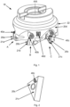
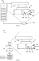
- Figure 1 illustrates example tool parts 20a,20b,20c,20d of a cutting tool 18.
- the tool parts 20a,20b,20c are cutting inserts 21a,21b,21c and the tool part 20d is a tool holder 22.
- the tool holder 22 is arranged to receive the cutting inserts 21a,21b,21c, at locations at the tool holder 22 illustrated as positions "A", "B” and "C" respectively.
- each cutting insert 21a,21b,21c comprising at least one cutting edge.
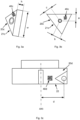
- Figure 2 illustrates an example tool part 20c in form of a cutting insert 21c with at least one cutting edge.
- each cutting edge of each cutting insert 21a,21b,21c is configured to be used for removing chips from a piece of material.
- an operator of a machine needs to locate the tool part 20a,20b,20c,20d and verify that the tool part 20a,20b,20c,20d is at a desired location before the machine operation can start.
- the operator of a cutting machine therefore needs to verify that e.g. the cutting edge of a cutting insert 21a,21b,21c is at a desired location. This is often done by visual inspection and sometimes by manual measurements by the operator of the machine, before the machine operation can be started by the operator.
- Today e.g. the distance from the tool holder rotation axis, AXt, as illustrated in Figure 1 , to each cutting edge of each cutting insert 21a,21b,21c may be determined by manual measurement by an operator of a machine.
- an operator of a machine lets the cutting edge come in contact with the piece of material before starting the machine operation in order to locate the cutting edge at a certain position in relation to the piece of material and e.g. determine the distance from the tool holder rotation axis AXt to the cutting edge of the cutting insert 21a,21b,21c.
- a first drawback of current approaches is that a cutting tool 18 can be erroneously positioned and therefore located at an undesirable location so that an incorrect distance from the piece of material to the cutting edge of the cutting insert 21a,21b,21c is used during the machine operation with the cutting tool 18, which in turn may cause severe damage to both the cutting tool 18 but also to the piece of material.
- a second drawback of current approaches is that even if the operator verifies that the tool part 20a,20b,20c,20d is located at a desirable location before the machine operation, the human error factor is one factor that can lead to an erroneously positioning of a tool part 20a,20b,20c,20d in a machine operation.
- a third drawback of the current approaches is that a lot of time is spent on localizing a tool part 20a,20b,20c,20d in relation to e.g. a machine and/or a material to be processed by the tool part 20a,20b,20c,20d when the tool part 20a,20b,20c,20d is attached to the machine. This time is costly and adds time to total manufacturing process of a product.
- a dimension of a specific tool part can be documented as a dimension value +/- a certain tolerance value. Often when manufacturing a specific tool part, the manufacturing process itself cannot be that precise, and therefore each manufactured tool part will have a true dimension that is within a certain tolerance, i.e. within the certain tolerance value, of the desired dimension value.
- This documented dimension can hence be used to some extent, but still the tolerance value will have to be measured for each individual tool part before the individual tool part is used e.g. in a machine operation. This means that time needs to be spent on e.g. verifying the exact dimension of the individual tool part.
- FIG 1 illustrates example tool parts 20a,20b,20c,20d according to an embodiment of the present disclosure.
- the first aspect of this disclosure shows a tool part 20a,20b,20c,20d for a cutting tool 18.
- the tool part 20a,20b,20c,20d is any of a cutting insert, a cutting edge, a milling tool part, a drilling tool part, a drill chuck, a milling cutter chuck or a tool holder.
- the tool part 20a,20b,20c,20d comprising an identification marker 40a,40b,40c,40d arranged at the tool part 20a,20b,20c,20d.
- the identification marker 40a,40b,40c,40d is at least any of, or a combination of at least any of, a proprietary machine readable code, an open source machine readable code, a two dimensional code, a three dimensional code, an image a Quick Response code, a High Capacity Colored Two Dimensional Code, a European Article Number code, a DataMatrix code or a MaxiCode.
- the identification marker 40a,40b,40c,40d is etched at the tool part 20a,20b,20c,20d. According to some embodiments the identification marker 40a,40b,40c,40d is a sticker attached at the tool part 20a,20b,20c,20d. According to some embodiments the identification marker 40a,40b,40c,40d painted at the tool part 20a,20b,20c,20d.
- the identification marker 40a,40b,40c,40d is a unique machine readable code associated with individual dimension information data idID, wherein the individual dimension information data idlD comprises at least one individually measured dimension of the tool part 20a,20b,20c,20d as measured when manufacturing the tool part 20a,20b,20c,20d.
- each identification marker 40a,40b,40c,40d at each tool part 20a,20b,20c,20d is unique so that no other tool part 20a,20b,20c,20d will have the very same identification marker 40a,40b,40c,40d. This enables the identification marker 40a,40b,40c,40d to be associated with individual dimension information data idID.
- the individual dimension information data idlD comprises at least one individually measured dimension of the tool part 20a,20b,20c,20d as measured at a certain tool part temperature when manufacturing the tool part 20a,20b,20c,20d.
- the individually measured dimension of the tool part 20a,20b,20c,20d is a dimension at a certain temperature.
- the dimension of the tool part may vary dependent on the temperature of the tool part, e.g. the tool part may expand at a higher temperature.
- the individually measured dimension is measured automatically by a measuring machine and/or manually by a measuring tool by an operator.
- each individual tool part is provided with a unique machine readable code which in turn can be associated with individual dimension information data idID for that specific individual tool part.
- the tool part 20a,20b,20c,20d is a cutting insert 21a,21b,21c and the individual dimension information data idlD comprises at least one individually measured dimension of the cutting insert 21a,21b,21c as measured when manufacturing the cutting insert 21a,21b,21c.
- Figure 2 illustrates an example tool part 20c in form of a cutting insert 21c with at least one cutting edge according to an embodiment of the present disclosure. As illustrated in Figure 2 , the example tool part 20c comprising an identification marker 40c arranged at the tool part 20c.
- Figures 3a-3b illustrate example individual dimensions of the cutting insert 21c according to an embodiment of the present disclosure.
- the height h and the width w are illustrated.
- the dimension "a" from the centre of the cutting insert 21c to a first cutting edge of the cutting insert 21c is illustrated.
- the dimension "b" from the centre of the cutting insert 21c to a second cutting edge of the cutting insert 21c is illustrated.
- the dimension "c" from the centre of the cutting insert 21c to a third cutting edge of the cutting insert 21c is illustrated.
- Figure 3c illustrates example individual dimensions of a tool part 20d according to an embodiment of the present disclosure.
- the example tool part 20d comprises an identification marker 40d arranged at the tool part 20d.
- the tool part 20d in the example in Figure 3c is a tool holder 22.
- the dimension "d" from the centre of a tool holder axis AXt of the tool holder 22 to the centre of a cutting insert attachment point, configured to receive a cutting insert 21a,21b,21c, is illustrated.
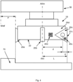
- Figure 4 illustrates example assembled tool parts 20a,20b,20c,20d attached to a machine 50 according to an embodiment of the present disclosure.
- the dimension "a" from the centre of the cutting insert 21c to a first cutting edge of the cutting insert 21c is illustrated together with the dimension "d" from the centre of a tool holder axis AXt of the tool holder 22 to the centre of an cutting insert attachment point for illustrating two dimensions with a common measurement point.
- an individually measured dimension of that specific cutting insert 21c can be used during e.g. a manufacturing process for a faster and more reliable positioning of the cutting insert 21c e.g. in relation to a piece of material to be processed in a machine operation.
- the individual dimension information data idID is coded in the machine readable code and the machine readable code is configured to be read by a reader device 10a,10b,10c and decoded by an electronic device 1a,1b,1c configured to be in communication with the reader device 10a,10b,10c.
- individual dimension information data can be obtained by a device which enables usage of the individual dimension information data by e.g. a machine and at the same time limits the need for human interaction which minimizes the risk of human errors.
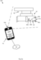
- FIG. 5a-5c each illustrates an example system according to an embodiment of the present disclosure.
- the system 100 comprises a reader device 10a,10b,10c for reading a machine readable code.
- the reader device 10a,10b,10c is any of a camera based reader, a video camera reader, a pen-type reader with photodiodes, a laser scanner, a charge-coupled device reader or a cell phone camera.
- the reader device 10a,10b,10c is a component integrated in an electronic device a stand-alone component.
- the reader device 10a,10b,10c is configured for reading a machine readable code, arranged at a tool part 20a,20b,20c,20d, during usage of the tool part 20a,20b,20c,20d in a machine operation by a machine 50.
- the system 100 further comprises an electronic device 1a,1b,1c configured to be connected with the reader device 10a,10b,10c.
- the electronic device is a portable electronic device 1a.
- the electronic device is a local electronic device 1b.
- the electronic device is a remote electronic device 1c.
- the electronic device 1a,1b,1c is configured to be connected to a communication network 60.
- Figure 5a illustrates an electronic device 1a in form of a smartphone, tablet, cellular phone, feature phone or any portable electronic device.
- the reader device 10a is the camera of a smartphone 1a.
- the electronic device 1a is a smartphone that is held by the machine operator when preparing tool parts 20a,20b,20c,20d for machine operation.
- the electronic device can also be a local electronic device 1b, e.g. installed as a part of a machine 50 as illustrated in figure 5b .
- the reader device 10b is a stand-alone reader device connected to the electronic device 1b and installed as a part of the machine 50.
- the electronic device is a remote server 1c connected to a reader device 10c via the communication network 60 as illustrated in Figure 5c .
- the machine 50 is operated from a remote location e.g. within a factory.
- the communication network 60 is a wireless communication network.
- the wireless communication network is a standardized wireless local area network such as a Wireless Local Area Network, WLAN, Bluetooth TM , ZigBee, Ultra-Wideband, UWB, Radio Frequency Identification, RFID, or similar network.
- the wireless communication network is a standardized wireless wide area network such as a Global System for Mobile Communications, GSM, Extended GSM, General Packet Radio Service, GPRS, Enhanced Data Rates for GSM Evolution, EDGE, Wideband Code Division Multiple Access, WCDMA, Long Term Evolution, LTE, Narrowband-loT, 5G, Worldwide Interoperability for Microwave Access, WiMAX or Ultra Mobile Broadband, UMB or similar network.
- the wireless communication network can also be a combination of both a wireless local area network and a wireless wide area network.
- communication network 60 can be a combination of a wired communication network and a wireless communication network.
- the communication network 60 is defined by common Internet Protocols.
- the electronic device 1a,1b,1c having a processing circuitry 102a,102b,102c configured to cause the system 100 to detect, by the reader device 10a,10b,10c, an identification marker 40a,40b,40c,40d at a tool part 20a,20b,20c,20d wherein the identification marker 40a,40b,40c,40d is a unique machine readable code.
- the processing circuitry 102a,102b,102c is further configured to read, by the reader device 10a,10b,10c, the unique machine readable code of the identification marker 40a,40b,40c,40d, and obtain from the unique machine readable code, individual dimension information data idlD comprising at least one individually measured dimension of the tool part 20a,20b,20c,20d as measured when manufacturing the tool part 20a,20b,20c,20d.
- the electronic device 1a,1b,1c further comprising a memory 103a,103b,103c.
- the individual dimension information data idID is stored in the memory 103a,103b,103c.
- an individual dimension, as measured when manufacturing the individual tool part can be obtained using the reader device, and used during usage of the individual tool part, e.g. at a tool part customer, which eliminates the need for measuring the individual dimension of the tool part at a later point in time, as needed with a tool part only associated with a dimension value +/- a certain tolerance value, e.g. This saves time before and/or during usage of the tool part in a machine operation at a tool part customer, and also improves measurement accuracy and reduces measurement errors caused by e.g. a human operator.
- the processing circuitry 102a,102b,102c is further configured to cause the system 100 to obtain machine dimension information data madID comprising at least a first assembly dimension defining a relation of the tool part 20a,20b,20c,20d to a machine 50 when the tool part 20a,20b,20c,20d is attached to the machine 50.
- an individual dimension of the tool part can be used in combination with a known dimension that is related to the machine when the tool part is assembled at the machine.
- Figure 4 illustrates example assembled tool parts 20a,20b,20c,20d attached to a machine 50.
- first tool part is attached to a machine 50 by a second tool part.
- a tool part is attached to a machine 50 by a tool holder 22.
- tool parts 20a,20b,20c are attached at a tool holder 22, and the tool holder 22 is attached to the machine 50.
- the machine dimension information data madID is obtained from a memory 103a,103b,103c connectable to the processing circuitry 102a,102b,102c.
- the machine dimension information data madID is obtained via at least any of a manual input of the machine dimension information data madID via a user interface 400a,400b,400c of the electronic device 1a,1b,1c, or via an automatic input of the machine dimension information data madID by a machine 50 connectable to the electronic device 1a,1b,1c.
- the machine dimension information data madID comprises a predetermined dimension relation and/or a predetermined angle relation of the tool part 20a,20b,20c,20d to a machine 50 when the tool part 20a,20b,20c,20d is attached to the machine 50.
- the machine dimension information data madID comprises an angle relation to a predetermined machine reference axis of the machine AXm in relation to a predetermined tool reference axis AXt of the tool part 20a,20b,20c,20d.
- the tool part 20d has a predetermined tool reference axis AXt that is in the example shared with the machine reference axis AXm, and hence the angle relation to the predetermined machine reference axis of the machine AXm in relation to the predetermined tool reference axis AXt is zero degrees.
- the machine dimension information data madID comprises a distance relation to a predetermined machine reference axis of the machine AXm in relation to a predetermined tool reference axis AXt of the tool part 20a,20b,20c,20d.
- a distance relation to a predetermined machine reference axis of the machine AXm in relation to a predetermined tool reference axis AXt of the tool part 20a,20b,20c,20d.
- the processing circuitry 102a,102b,102c is further configured to cause the system 100 to determine first assembly dimension d of the tool part 20a,20b,20c,20d in relation to the machine 50, based on the first individual dimension information data 1idID and the machine dimension information data madID.
- the distance between the predetermined machine reference axis of the machine AXm and the predetermined tool reference axis to the tool part 20c is the distance d to an assembly point of the tool part 20d where the tool part 20c is attached.
- an individual dimension of the tool part can be used in combination with a known dimension that is related to the machine in order to determine a first assembly dimension of the tool part in relation to the machine, e.g. the position of the tool part in relation to the machine.
- the processing circuitry 102a,102b,102c is further configured to cause the system 100 to detect, by the reader device 10a,10b,10c, a first identification marker 40c at a first tool part 20c and a second identification marker 40d at a second tool part 20d, read, by the reader device 10a,10b,10c, the unique machine readable code of the first identification marker 40c and the unique machine readable code of the second identification marker 40d.
- the processing circuitry 102a,102b,102c is further configured to obtain from the unique machine readable code of the first identification marker 40c a first individual dimension information data 1idlD comprising at least one individually measured dimension of the first tool part 20c as measured when manufacturing the first tool part 20c, and obtain from the unique machine readable code of the second identification marker 40d a second individual dimension information data 2idlD comprising at least one individually measured dimension of the second tool part 20d as measured when manufacturing the second tool part 20d.
- the processing circuitry 102a,102b,102c is further configured to determine a second assembly dimension L of the first tool part 20c and the second tool part 20d, based on the first individual dimension information data 1idlD and the second individual dimension information data 2idID.
- an assembly dimension of the first tool part and the second tool part can be determined, e.g. when the first tool part is attached to the second tool part.
- the second assembly dimension L of the first tool part 20c and the second tool part 20d comprising the sum of the dimension d of the second individual dimension information data 2idID plus the dimension a of the first individual dimension information data 1idID.
- the first tool part 20c is configured to be attached to the second tool part 20d
- the second tool part 20d is configured to be attached to a machine 50
- the processing circuitry 102a,102b,102c is further configured to cause the system 100 to determine a third assembly dimension of the first tool part 20c and the second tool part 20d in relation to the machine 50, based on the first individual dimension information data 1idID, the second individual dimension information data 2idID and the machine dimension information data madID.
- the third assembly dimension of the first tool part 20c and the second tool part 20d comprising the sum of the dimension d of the second individual dimension information data 2idID plus the dimension a of the first individual dimension information data 1idID and in the example, the machine dimension information data madID defines the machine reference axis AXm to be common with the predetermined tool reference axis AXt of the second tool part 20d when the second tool part 20d is attached to the machine 50.
- the first assembly dimension of the first tool part 20c and the second tool part 20d in relation to the machine 50 is further based on an offset distance q between the predetermined tool reference axis AXt and the predetermined machine reference axis of the machine AXm.
- the offset distance q between the predetermined tool reference axis AXt and the predetermined machine reference axis of the machine AXm is obtained from a memory 103a,103b,103c comprising tool and machine dimension data.
- the machine dimension information data madID defines the machine reference axis AXm to be offset distance q from the predetermined tool reference axis AXt of the second tool part 20d when the second tool part 20d is attached to the machine 50, and the third assembly dimension in relation to the machine reference axis AXm is hence q+d+a.
- an assembly dimension of the first tool part and the second tool part in relation to a machine can be determined when the first tool part is attached to the second tool part, and the second tool part is attached to the machine to e.g. determine a distance from a known reference point or axis of the machine to an edge of the first tool part.
- a machine operation by a tool part in form of a cutting insert 21c is used for removing chips from a piece of material 70 that is in a fixed position in relation to the machine 50.
- a certain location of the cutting edge of the cutting insert 21c in relation to the piece of material 70 is required. This location can be determined in relation to how the cutting insert 21c is located in relation to the machine 50 and/or in relation to the piece of material 70.
- the location of the cutting edge of the cutting insert 21c in relation to the piece of material 70 is determined to be at a distance P between the piece of material 70 and a fixed machine reference point Mref.
- the distance P can be achieved by either using a new cutting insert with the very same dimensions as the previous cutting insert, or e.g. by adjusting the position of the machine reference axis AXm, by the machine 50, so that the new cutting edge of the new cutting insert is determined to be at a distance P between the piece of material 70 and the machine reference point Mref.
- determining the distance P can be achieved by first knowing the second assembly dimension L of the cutting insert 21c and the tool holder 22, in relation to the machine 50.
- the relation to the machine 50 is based on the machine dimension information data madID, in this case related to the fixed machine reference point Mref.
- the first individual dimension information data 1idlD of the new cutting insert, and the second individual dimension information data 2idID of the tool holder 22, is then used to adjust the position of the machine reference axis AXm, by the machine 50, so that the new cutting edge of the new cutting insert is determined to be at a position in space that is at a distance P between the piece of material 70 and the machine reference point Mref.
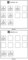
- Figures 6a-6b illustrate example schematic data relations of associated individual dimension information data.
- Figure 6a illustrates an example identification marker with the unique machine readable code of "AA0002".
- the individual dimension information data idlD comprises plurality of individually measured dimensions of the tool part 20a,20b,20c,20d as measured when manufacturing the tool part 20a,20b,20c,20d.
- the dimensions a, b and c are example of individually measured dimensions of the tool part 20a,20b,20c,20d as measured when manufacturing the tool part 20a,20b,20c,20d.
- the individually measured dimension of the tool part 20a,20b,20c,20d is a dimension at a certain temperature.
- the dimension of the tool part may vary dependent on the temperature of the tool part, e.g. the tool part may expand at a higher temperature.
- the individually measured dimension of the tool part 20a,20b,20c,20d is a dimension at a certain temperature and/or a relation to a function for determining a dimension at a certain temperature.
- the expansion of a dimension of the tool part at a certain temperature is predetermined and part of the individual dimension information data idID.
- Figure 6b illustrates an example identification marker with the unique machine readable code of "BB2342".
- the system 100 comprises a temperature sensor device configured to determine the current temperature of the tool part 20a,20b,20c,20d, and the processing circuitry 102a,102b,102c is configured to cause the system 100 to obtain from the unique machine readable code, individual dimension information data idlD comprising at least one individually measured dimension of the tool part 20a,20b,20c,20d as measured when manufacturing the tool part 20a,20b,20c,20d wherein the at least one individually measured dimension of the tool part 20a,20b,20c,20d is further dependent to the current temperature of the tool part 20a,20b,20c,20d.
- the temperature sensor device is any of an infrared camera or a thermometer.
- the reader device 10a,10b,10c is configured to obtain the current temperature of the tool part 20a,20b,20c,20d.
- the second tool part 20d has a predetermined tool reference axis AXt with a known relation to a predetermined machine reference axis of the machine AXm when the second tool part 20d is attached to the machine 50 that is comprised in the machine dimension information data madID.
- the predetermined tool reference axis AXt is common with, perpendicular to, or parallel to the predetermined machine reference axis of the machine AXm.
- the predetermined machine reference axis of the machine AXm is defined by a rotation of the second tool part 20d when the second tool part 20d is inserted into the machine 50.
- the reference axis of the machine AXm is defined by a rotation of a work piece that is inserted into the machine 50.
- the individual dimension information data idID is obtained by decoding the unique machine readable code of the identification marker 40a,40b,40c,40d and from the decoded information obtain the individual dimension information data idID.
- information about the individual dimension can be coded and stored in the unique machine readable code itself that is available on the tool part.
- the individual dimension information data idID is obtained by comparing the unique machine readable code with association data the system comprises individual dimension information data idlD of the tool part 20a,20b,20c,20d provided with the unique machine readable code and obtaining the individual dimension information data idlD from a memory 103a,103b,103c.
- information about the individual dimension can be stored in a memory that e.g. is a remote memory 400c, and the information data idlD can be stored and managed by a tool part manufacturer for a tool part customer.
- the processing circuitry 102a,102b,102c is further configured to cause the system 100 to output the at least one individually measured dimension of the tool part 20a,20b,20c,20d as measured when manufacturing the tool part 20a,20b,20c,20d via a user interface 400a,400b,400c of the electronic device 1a,1b,1c.
- the processing circuitry 102a,102b,102c is further configured to output the at least one individually measured dimension of the tool part 20a,20b,20c,20d as measured when manufacturing the tool part 20a,20b,20c,20d as input data to a machine, connectable to the electronic device 1a,1b,1c, configured to perform an operation of the tool part 20a,20b,20c,20d.
- the processing circuitry 102a,102b,102c is further configured to cause the system 100 to output a determined distance to a part of a tool part 20c based on the machine dimension information data madID via a user interface 400a,400b,400c of the electronic device 1a,1b,1c.
- Figure 7 illustrates a flow chart of example method steps according to an embodiment of the disclosure.
- the method comprises the step of S1a detecting, by a reader device 10a,10b,10c, an identification marker 40a,40b,40c,40d at a tool part 20a,20b,20c,20d wherein the identification marker 40a,40b,40c,40d is a unique machine readable code, the step of S2a reading, by the reader device 10a,10b,10c, the unique machine readable code of the identification marker 40a,40b,40c,40d, and the step of S3a obtaining from the unique machine readable code individual dimension information data idlD comprising at least one individually measured dimension of the tool part 20a,20b,20c,20d as measured when manufacturing the tool part 20a,20b,20c,20d.
- individual dimension information data idlD comprising at least one individually measured dimension of the tool part 20a,20b,20c,20d as measured when manufacturing the tool part
- each individual tool part is provided with a unique machine readable code which in turn can be associated with individual dimension information data idID for that specific individual tool part.
- the method further comprises the step of S4 obtaining machine dimension information data madID comprising at least a first assembly dimension defining a relation of the tool part 20a,20b,20c,20d to a machine 50 when the tool part 20a,20b,20c,20d is attached to the machine 50.
- an individual dimension of the tool part can be used in combination with a known dimension that is related to the machine when the tool part is assembled at the machine.
- the method further comprises the step of S5a determining first assembly dimension d of the tool part 20a,20b,20c,20d in relation to the machine 50, based on the first individual dimension information data 1idID and the machine dimension information data madID.
- an individual dimension of the tool part can be used in combination with a known dimension that is related to the machine in order to determine a first assembly dimension of the tool part in relation to the machine, e.g. the position of the tool part in relation to the machine.
- the method further comprises the step of S1b detecting, by the reader device 10a,10b,10c, a first identification marker 40c at a first tool part 20c and a second identification marker 40d at a second tool part 20d, the step of S2b reading, by the reader device 10a,10b,10c, the unique machine readable code of the first identification marker 40c and the unique machine readable code of the second identification marker 40d.
- the method further comprises the step of S3b obtaining from the unique machine readable code of the first identification marker 40c a first individual dimension information data 1idID comprising at least one individually measured dimension of the first tool part 20c as measured when manufacturing the first tool part 20c, and obtaining from the unique machine readable code of the second identification marker 40d a second individual dimension information data 2idlD comprising at least one individually measured dimension of the second tool part 20d as measured when manufacturing the second tool part 20d.
- the method further comprises the step of S5b determining a second assembly dimension L of the first tool part 20c and the second tool part 20d, based on the first individual dimension information data 1idlD and the second individual dimension information data 2idID.
- an assembly dimension of the first tool part and the second tool part can be determined, e.g. when the first tool part is attached to the second tool part.
- the method further comprises the step of determining a third assembly dimension of the first tool part 20c and the second tool part 20d in relation to the machine 50, based on the first individual dimension information data 1idID, the second individual dimension information data 2idID and the machine dimension information data madID.
- an assembly dimension of the first tool part and the second tool part in relation to a machine can be determined when the first tool part is attached to the second tool part, and the second tool part is attached to the machine to e.g. determine a distance from a known reference point or axis of the machine to an edge of the first tool part.
- the individual dimension information data idID is obtained by decoding the unique machine readable code of the identification marker 40a,40b,40c,40d and from the decoded information obtaining the individual dimension information data idID, and/or by comparing the unique machine readable code with association data the method comprises individual dimension information data idlD of the tool part 20a,20b,20c,20d provided with the unique machine readable code and obtaining the individual dimension information data idlD from a memory 103a,103b,103c.
- information about the individual dimension can be coded and stored in the unique machine readable code itself that is available on the tool part.
- a memory 103a,103b,103c that is e.g. a remote memory 103c
- the individual dimension can be managed by a tool part manufacturer for a tool part customer.
- Figure 8 illustrates a computer program product 500 according to a third aspect of this disclosure.
- the computer program product 500 comprises a non-transitory computer readable medium, having thereon a computer program comprising program instructions, the computer program being loadable into a processing circuitry 102a,102b,102c and configured to cause execution of the method when the computer program is run by the processing circuitry 102a,102b,102c.
Landscapes
- Engineering & Computer Science (AREA)
- Physics & Mathematics (AREA)
- General Physics & Mathematics (AREA)
- Automation & Control Theory (AREA)
- Health & Medical Sciences (AREA)
- Toxicology (AREA)
- Artificial Intelligence (AREA)
- Computer Vision & Pattern Recognition (AREA)
- General Health & Medical Sciences (AREA)
- Theoretical Computer Science (AREA)
- Electromagnetism (AREA)
- Human Computer Interaction (AREA)
- Manufacturing & Machinery (AREA)
- Machine Tool Sensing Apparatuses (AREA)
- General Factory Administration (AREA)
Claims (12)
- System (100) zur Verwendung einer Identifikationsmarkierung (40a, 40b, 40c, 40d) auf einem Werkzeugteil (20a, 20b, 20c, 20d), die zum Feststellen einer Abmessung des Werkzeugteils (20a, 20b, 20c, 20d) verwendbar ist, wobei das System (100) Folgendes aufweist:eine Lesevorrichtung (10a, 10b, 10c) zum Lesen eines maschinenlesbaren Codes,eine elektronische Vorrichtung (1a, 1b, 1c), die so eingerichtet ist, dass sie mit der Lesevorrichtung (10a, 10b, 10c) verbunden ist,wobei die elektronische Vorrichtung (1a, 1b, 1c) eine Verarbeitungsschaltung (102a, 102b, 102c) aufweist, die so eingerichtet ist, dass sie das System (100) veranlasst:- mit der Lesevorrichtung (10a, 10b, 10c) eine Identifikationsmarkierung (40a, 40b, 40c, 40d) an einem Werkzeugteil (20a, 20b, 20c, 20d) zu erfassen, wobei die Identifikationsmarkierung (40a, 40b, 40c, 40d) ein bestimmter maschinenlesbarer Code ist,- mit der Lesevorrichtung (10a, 10b, 10c) den bestimmten maschinenlesbaren Code der Identifikationsmarkierung (40a, 40b, 40c, 40d) zu lesen, und- aus dem bestimmten maschinenlesbaren Code individuelle Abmessungsinformationsdaten (idID) zu erhalten, die wenigstens eine individuell gemessene Abmessung des Werkzeugteils (20a, 20b, 20c, 20d) umfassen, wie sie bei der Herstellung des Werkzeugteils (20a, 20b, 20c, 20d) gemessen wurde, wobei die Verarbeitungsschaltung (102a, 102b, 102c) ferner so eingerichtet ist, dass sie das System (100) veranlasst- mit der Lesevorrichtung (10a, 10b, 10c) eine erste Identifikationsmarkierung (40c) an einem ersten Werkzeugteil (20c) und eine zweite Identifikationsmarkierung (40d) an einem zweiten Werkzeugteil (20d) zu erkennen,- mit der Lesevorrichtung (10a, 10b, 10c) den bestimmten maschinenlesbaren Code der ersten Identifikationsmarkierung (40c) und den bestimmten maschinenlesbaren Code der zweiten Identifikationsmarkierung (40d) zu lesen,- aus dem bestimmten maschinenlesbaren Code der ersten Identifikationsmarkierung (40c) erste individuelle Abmessungsinformationsdaten (1idlD) zu erhalten, die wenigstens eine individuell gemessene Abmessung des ersten Werkzeugteils (20c) umfassen, wie sie bei der Herstellung des ersten Werkzeugteils (20c) gemessen wurde, und aus dem bestimmten maschinenlesbaren Code der zweiten Identifikationsmarkierung (40d) zweite individuelle Abmessungsinformationsdaten (2idID) zu erhalten, die wenigstens eine individuell gemessene Abmessung des zweiten Werkzeugteils (20d) umfassen, wie sie bei der Herstellung des zweiten Werkzeugteils (20d) gemessen wurde, und- eine zweite Montage-Abmessung (L) des ersten Werkzeugteils (20c) und des zweiten Werkzeugteils (20d) auf der Grundlage der ersten individuellen Abmessungsinformationsdaten (1idID) und der zweiten individuellen Abmessungsinformationsdaten (2idID) festzustellen.
- System (100) nach Anspruch 1, wobei die Verarbeitungsschaltung (102a, 102b, 102c) ferner so eingerichtet ist, dass sie das System (100) veranlasst,- Maschinenabmessung-Informationsdaten (madID) zu erhalten, die wenigstens eine erste Montage-Abmessung umfassen, die eine Relation des Werkzeugteils (20a, 20b, 20c, 20d) zu einer Maschine (50) definiert, wenn das Werkzeugteil (20a, 20b, 20c, 20d) an der Maschine (50) angebracht ist.
- System (100) nach Anspruch 2, wobei die Verarbeitungsschaltung (102a, 102b, 102c) ferner so eingerichtet ist, dass sie das System (100) veranlasst,- eine erste Montage-Abmessung (d) des Werkzeugteils (20a, 20b, 20c, 20d) in Bezug auf die Maschine (50) festzustellen, basierend auf den individuellen Abmessungsinformationsdaten (idID) und den Maschinenabmessung-Informationsdaten (madID).
- System (100) nach einem der Ansprüche 1 bis 3, wobei die Verarbeitungsschaltung (102a, 102b, 102c) ferner so eingerichtet ist, dass sie das System veranlasst,- Maschinen-Abmessungsinformationsdaten (madID) zu erhalten, die wenigstens eine erste Anordnungsabmessung umfassen, die eine Relation des ersten Werkzeugteils (20c) zu einer Maschine (50) definiert, und eine zweite Anordnungsabmessung, die eine Relation des zweiten Werkzeugteils (20d) zu der Maschine (50) definiert, wenn das erste Werkzeugteil (20c) an dem zweiten Werkzeugteil (20d) angebracht ist und das zweite Werkzeugteil (20d) an der Maschine (50) angebracht ist, und- eine dritte Anordnungsabmessung des ersten Werkzeugteils (20c) und des zweiten Werkzeugteils (20d) in Bezug auf die Maschine (50) auf der Grundlage der ersten individuellen Abmessungsinformationsdaten (1idID), der zweiten individuellen Abmessungsinformationsdaten (2idID) und der Maschinen-Abmessungsinformationsdaten (madID) feststellt.
- System (100) nach einem der Ansprüche 1 bis 4, wobei die individuellen Abmessungsinformationsdaten (idID) durch Dekodieren des bestimmten maschinenlesbaren Codes der Identifikationsmarkierung (40a, 40b, 40c, 40d) erhalten werden und aus den dekodierten Informationen die individuellen Abmessungsinformationsdaten (idID) erhalten werden.
- System (100) nach einem der Ansprüche 1-5, wobei die individuellen Abmessungsinformationsdaten (idID) durch Vergleichen des bestimmten maschinenlesbaren Codes mit Vergleichsdaten, die individuelle Abmessungsinformationsdaten (idID) des Werkzeugteils (20a, 20b, 20c, 20d) umfassen, das mit dem bestimmten maschinenlesbaren Code bereitgestellt wird, und durch Erhalten der individuellen Abmessungsinformationsdaten (idID) aus einem Speicher (103a, 103b, 103c) erhalten werden.
- Verfahren zur Verwendung einer Identifikationsmarkierung (40a, 40b, 40c, 40d) auf einem Werkzeugteil (20a, 20b, 20c, 20d), die zur Feststellung einer Abmessung des Werkzeugteils (20a, 20b, 20c, 20d) verwendbar ist, wobei das Verfahren Folgendes umfasst:- (S1a) Erfassen einer Identifikationsmarkierung 51 (40a, 40b, 40c, 40d) an einem Werkzeugteil (20a, 20b, 20c, 20d) durch eine Lesevorrichtung (10a, 10b, 10c), wobei die Identifikationsmarkierung (40a, 40b, 40c, 40d) ein bestimmter maschinenlesbarer Code ist,- (S2a) Lesen des bestimmten maschinenlesbaren Codes der Identifikationsmarkierung (40a, 40b, 40c, 40d) mit der Lesevorrichtung (10a, 10b, 10c), und- (S3a) Erhalten von individuellen Abmessungsinformationsdaten (idID), die wenigstens eine individuell gemessene Abmessung des Werkzeugteils (20a, 20b, 20c, 20d) umfassen, wie sie bei der Herstellung des Werkzeugteils (20a, 20b, 20c, 20d) gemessen wurde, aus dem bestimmten maschinenlesbaren Code, wobei das Verfahren ferner umfasst:- (S1b) Erfassen einer ersten Identifikationsmarkierung (40c) an einem ersten Werkzeugteil (20c) und einer zweiten Identifikationsmarkierung (40d) an einem zweiten Werkzeugteil (20d) mit der Lesevorrichtung (10a, 10b, 10c),- (S2b) Lesen des bestimmten maschinenlesbaren Codes der ersten Identifikationsmarkierung (40c) und des bestimmten maschinenlesbaren Codes der zweiten Identifikationsmarkierung (40d) mit der Lesevorrichtung (10a, 10b, 10c),- (S3b) Erhalten von ersten individuellen Abmessungsinformationsdaten (1idID), die wenigstens eine individuell gemessene Abmessung des ersten Werkzeugteils (20c) umfassen, wie sie bei der Herstellung des ersten Werkzeugteils (20c) gemessen wurde, aus dem bestimmten maschinenlesbaren Code des ersten Identifikationsmarkers (40c), und Erhalten von zweiten individuellen Abmessungsinformationsdaten (2idID), die wenigstens eine individuell gemessene Abmessung des zweiten Werkzeugteils (20d) umfassen, wie sie bei der Herstellung des zweiten Werkzeugteils (20d) gemessen wurde, aus dem bestimmten maschinenlesbaren Code des zweiten Identifikationsmarkers (40d) und- (S5b) Feststellen einer zweiten Anordnungsabmessung (L) des ersten Werkzeugteils (20c) und des zweiten Werkzeugteils (20d), basierend auf den ersten individuellen Abmessungsinformationsdaten (1idID) und den zweiten individuellen Abmessungsinformationsdaten (2idID).
- Verfahren nach Anspruch 7, wobei das Verfahren ferner Folgendes umfasst:- (S4) Erhalten von Maschinen-Abmessungsinformationsdaten (madID), die wenigstens eine erste Anordnungsabmessung umfassen, die eine Relation des Werkzeugteils (20a, 20b, 20c, 20d) zu einer Maschine (50) definiert, wenn das Werkzeugteil (20a, 20b, 20c, 20d) an der Maschine (50) angebracht ist.
- Verfahren nach Anspruch 8, wobei das Verfahren ferner Folgendes umfasst:- (S5a) Feststellen der ersten Anordnungsabmessung (d) des Werkzeugteils (20a, 20b, 20c, 20d) in Bezug auf die Maschine (50), basierend auf den individuellen Abmessungsinformationsdaten (idID) und den Maschinenabmessungsinformationsdaten (madID).
- Verfahren nach einem der Ansprüche 7-9, wobei das Verfahren weiterhin Folgendes aufweist:- (S6) Erhalten von Maschinen-Abmessungsinformationsdaten (madID), die wenigstens eine erste Anordnungsabmessung umfassen, die eine Relation des ersten Werkzeugteils (20c) zu einer Maschine (50) definiert, und eine zweite Anordnungsabmessung, die eine Relation des zweiten Werkzeugteils (20d) zu der Maschine (50) definiert, wenn das erste Werkzeugteil (20c) an dem zweiten Werkzeugteil (20d) angebracht ist und das zweite Werkzeugteil (20d) an der Maschine (50) angebracht ist, und- (S7) Feststellen einer dritten Anordnungsabmessung des ersten Werkzeugteils (20c) und des zweiten Werkzeugteils (20d) in Bezug auf die Maschine (50), basierend auf den ersten individuellen Abmessungsinformationsdaten (1idID), den zweiten individuellen Abmessungsinformationsdaten (2idID) und den Maschinenabmessungsinformationsdaten (madID).
- Verfahren nach einem der Ansprüche 7-10, wobei die individuellen Abmessungsinformationsdaten (idID) erhalten werden durch:- Dekodieren des bestimmten maschinenlesbaren Codes der Identifikationsmarke (40a, 40b, 40c, 40d) und Erhalten der individuellen Abmessungsinformationsdaten (idID) aus den dekodierten Informationen, und/oder- durch Vergleichen des bestimmten maschinenlesbaren Codes mit Vergleichsdaten, die individuelle Abmessungsinformationsdaten (idID) des Werkzeugteils (20a, 20b, 20c, 20d) umfassen, das mit dem bestimmten maschinenlesbaren Code bereitgestellt wird, und Erhalten der individuellen Abmessungsinformationsdaten (idID) aus einem Speicher (103a, 103b, 103c).
- Computerprogrammprodukt (500), das ein nicht-transitorisches, computerlesbares Medium enthält, das ein Computerprogramm aufweist, welches Programmanweisungen umfasst, wobei das Computerprogramm in eine Verarbeitungsschaltung (102a, 102b, 102c) geladen werden kann und so eingerichtet ist, dass es die Ausführung aller Schritte des Verfahrens nach einem der Ansprüche 7-11 bewirkt, wenn das Computerprogramm von der Verarbeitungsschaltung (102a, 102b, 102c) ausgeführt wird.
Applications Claiming Priority (2)
| Application Number | Priority Date | Filing Date | Title |
|---|---|---|---|
| EP20173171 | 2020-05-06 | ||
| PCT/EP2021/060674 WO2021224028A1 (en) | 2020-05-06 | 2021-04-23 | A tool part, system, method, and a computer program for determining a dimension of the tool part |
Publications (3)
| Publication Number | Publication Date |
|---|---|
| EP4147100A1 EP4147100A1 (de) | 2023-03-15 |
| EP4147100B1 true EP4147100B1 (de) | 2024-11-06 |
| EP4147100C0 EP4147100C0 (de) | 2024-11-06 |
Family
ID=70613591
Family Applications (1)
| Application Number | Title | Priority Date | Filing Date |
|---|---|---|---|
| EP21720496.5A Active EP4147100B1 (de) | 2020-05-06 | 2021-04-23 | Werkzeugteil, system, verfahren und computerprogramm zur bestimmung einer abmessung des werkzeugteils |
Country Status (6)
| Country | Link |
|---|---|
| US (1) | US12197182B2 (de) |
| EP (1) | EP4147100B1 (de) |
| JP (1) | JP7699609B2 (de) |
| KR (1) | KR20230008769A (de) |
| CN (1) | CN115485635B (de) |
| WO (1) | WO2021224028A1 (de) |
Families Citing this family (2)
| Publication number | Priority date | Publication date | Assignee | Title |
|---|---|---|---|---|
| EP3907571B1 (de) * | 2020-05-06 | 2023-08-02 | Seco Tools Ab | Werkzeugteil, system, verfahren und computerprogrammprodukt zur bestimmung von werkzeugverschleiss |
| CN116890263B (zh) * | 2023-09-04 | 2023-11-24 | 山东豪迈数控机床有限公司 | 一种数控机床对刀方法、装置、控制器及数控机床 |
Family Cites Families (13)
| Publication number | Priority date | Publication date | Assignee | Title |
|---|---|---|---|---|
| JPS57138562A (en) * | 1981-02-20 | 1982-08-26 | Okuma Mach Works Ltd | Correction device for tool |
| JP2003071672A (ja) * | 2001-09-03 | 2003-03-12 | Olympus Optical Co Ltd | 識別手段付き工具及び工作機械システム |
| CN101192162A (zh) * | 2006-11-20 | 2008-06-04 | 广达电脑股份有限公司 | 模块管理刀锋片系统及其程序代码的更新方法 |
| JP4989568B2 (ja) * | 2008-06-26 | 2012-08-01 | 住友金属工業株式会社 | 二次元コード読取装置、二次元コード読取方法、中心軸に直交する断面が略円形の部材の製造履歴情報管理方法、及び、該管理方法を用いた前記部材の製造方法 |
| US8209076B2 (en) * | 2008-10-06 | 2012-06-26 | International Business Machines Corporation | Tracking vehicle maintenance using sensor detection |
| CN107463594A (zh) * | 2010-11-25 | 2017-12-12 | 彗星集团有限公司 | 计算机网络的服务器 |
| US10146976B2 (en) * | 2012-03-01 | 2018-12-04 | Proper Digital LLC | Tooling system |
| US9643273B2 (en) * | 2013-10-14 | 2017-05-09 | Hypertherm, Inc. | Systems and methods for configuring a cutting or welding delivery device |
| EP3078443B1 (de) | 2015-03-20 | 2019-10-16 | Matthew Fagan | Verfahren und system zum verbesserten numerisch gesteuerten plasmaschneiden von teilen von einem werkstück |
| CN107150146A (zh) * | 2016-03-04 | 2017-09-12 | 北新集团建材股份有限公司 | 飞剪控制系统 |
| CN106934433A (zh) * | 2017-03-20 | 2017-07-07 | 深圳市美思美科智能科技股份有限公司 | 一种刀具终端二维码识别跟踪系统 |
| NL2020658B1 (en) * | 2018-03-23 | 2019-10-02 | Alt Tech B V | Improved Die Cutting System and Tool Information Management System therefore |
| JP7216904B2 (ja) * | 2018-09-13 | 2023-02-02 | 三菱マテリアル株式会社 | 切削インサート、切刃状態管理システムおよび切削インサートの製造方法 |
-
2021
- 2021-04-23 CN CN202180032806.7A patent/CN115485635B/zh active Active
- 2021-04-23 JP JP2022567373A patent/JP7699609B2/ja active Active
- 2021-04-23 KR KR1020227042207A patent/KR20230008769A/ko active Pending
- 2021-04-23 WO PCT/EP2021/060674 patent/WO2021224028A1/en not_active Ceased
- 2021-04-23 EP EP21720496.5A patent/EP4147100B1/de active Active
- 2021-04-23 US US17/922,745 patent/US12197182B2/en active Active
Also Published As
| Publication number | Publication date |
|---|---|
| CN115485635B (zh) | 2025-09-09 |
| US12197182B2 (en) | 2025-01-14 |
| JP7699609B2 (ja) | 2025-06-27 |
| JP2023524549A (ja) | 2023-06-12 |
| EP4147100A1 (de) | 2023-03-15 |
| US20230205162A1 (en) | 2023-06-29 |
| KR20230008769A (ko) | 2023-01-16 |
| WO2021224028A1 (en) | 2021-11-11 |
| EP4147100C0 (de) | 2024-11-06 |
| CN115485635A (zh) | 2022-12-16 |
Similar Documents
| Publication | Publication Date | Title |
|---|---|---|
| EP4147100B1 (de) | Werkzeugteil, system, verfahren und computerprogramm zur bestimmung einer abmessung des werkzeugteils | |
| CN110103073B (zh) | 异常判别装置、异常判别系统、异常判别方法、存储介质 | |
| KR102765328B1 (ko) | 절삭날의 사용을 추적하는 시스템 및 방법 | |
| JP6694643B2 (ja) | ワークの加工方法 | |
| EP3907571B1 (de) | Werkzeugteil, system, verfahren und computerprogrammprodukt zur bestimmung von werkzeugverschleiss | |
| CN113453835A (zh) | 用于设置工具机的方法和制造系统 | |
| US12070827B2 (en) | Control mechanism, tool replacement equipment and tool replacement method | |
| EP3757697B1 (de) | Elektronische vorrichtung und verfahren zur verwaltung der verfolgbarkeit eines schneidwerkzeugs | |
| EP3907029B1 (de) | System, verfahren und computerprogrammprodukt zur verminderung der gefahr einer fehlerhaften handhabung eines werkzeugs in einem maschinenbetrieb | |
| CN105689903A (zh) | 在金属板总成上成形孔的系统及方法 | |
| CN120641243A (zh) | 机床及机床的控制方法 | |
| JP2021098257A (ja) | ブローチの管理システム |
Legal Events
| Date | Code | Title | Description |
|---|---|---|---|
| STAA | Information on the status of an ep patent application or granted ep patent |
Free format text: STATUS: UNKNOWN |
|
| STAA | Information on the status of an ep patent application or granted ep patent |
Free format text: STATUS: THE INTERNATIONAL PUBLICATION HAS BEEN MADE |
|
| PUAI | Public reference made under article 153(3) epc to a published international application that has entered the european phase |
Free format text: ORIGINAL CODE: 0009012 |
|
| STAA | Information on the status of an ep patent application or granted ep patent |
Free format text: STATUS: REQUEST FOR EXAMINATION WAS MADE |
|
| 17P | Request for examination filed |
Effective date: 20221206 |
|
| AK | Designated contracting states |
Kind code of ref document: A1 Designated state(s): AL AT BE BG CH CY CZ DE DK EE ES FI FR GB GR HR HU IE IS IT LI LT LU LV MC MK MT NL NO PL PT RO RS SE SI SK SM TR |
|
| DAV | Request for validation of the european patent (deleted) | ||
| DAX | Request for extension of the european patent (deleted) | ||
| GRAP | Despatch of communication of intention to grant a patent |
Free format text: ORIGINAL CODE: EPIDOSNIGR1 |
|
| GRAP | Despatch of communication of intention to grant a patent |
Free format text: ORIGINAL CODE: EPIDOSNIGR1 |
|
| STAA | Information on the status of an ep patent application or granted ep patent |
Free format text: STATUS: GRANT OF PATENT IS INTENDED |
|
| RIC1 | Information provided on ipc code assigned before grant |
Ipc: G05B 19/12 20060101AFI20240524BHEP |
|
| INTG | Intention to grant announced |
Effective date: 20240614 |
|
| GRAS | Grant fee paid |
Free format text: ORIGINAL CODE: EPIDOSNIGR3 |
|
| GRAA | (expected) grant |
Free format text: ORIGINAL CODE: 0009210 |
|
| STAA | Information on the status of an ep patent application or granted ep patent |
Free format text: STATUS: THE PATENT HAS BEEN GRANTED |
|
| AK | Designated contracting states |
Kind code of ref document: B1 Designated state(s): AL AT BE BG CH CY CZ DE DK EE ES FI FR GB GR HR HU IE IS IT LI LT LU LV MC MK MT NL NO PL PT RO RS SE SI SK SM TR |
|
| REG | Reference to a national code |
Ref country code: GB Ref legal event code: FG4D |
|
| REG | Reference to a national code |
Ref country code: CH Ref legal event code: EP |
|
| REG | Reference to a national code |
Ref country code: DE Ref legal event code: R096 Ref document number: 602021021401 Country of ref document: DE |
|
| REG | Reference to a national code |
Ref country code: IE Ref legal event code: FG4D |
|
| U01 | Request for unitary effect filed |
Effective date: 20241106 |
|
| U07 | Unitary effect registered |
Designated state(s): AT BE BG DE DK EE FI FR IT LT LU LV MT NL PT RO SE SI Effective date: 20241112 |
|
| PG25 | Lapsed in a contracting state [announced via postgrant information from national office to epo] |
Ref country code: HR Free format text: LAPSE BECAUSE OF FAILURE TO SUBMIT A TRANSLATION OF THE DESCRIPTION OR TO PAY THE FEE WITHIN THE PRESCRIBED TIME-LIMIT Effective date: 20241106 Ref country code: IS Free format text: LAPSE BECAUSE OF FAILURE TO SUBMIT A TRANSLATION OF THE DESCRIPTION OR TO PAY THE FEE WITHIN THE PRESCRIBED TIME-LIMIT Effective date: 20250306 |
|
| PG25 | Lapsed in a contracting state [announced via postgrant information from national office to epo] |
Ref country code: ES Free format text: LAPSE BECAUSE OF FAILURE TO SUBMIT A TRANSLATION OF THE DESCRIPTION OR TO PAY THE FEE WITHIN THE PRESCRIBED TIME-LIMIT Effective date: 20241106 |
|
| PG25 | Lapsed in a contracting state [announced via postgrant information from national office to epo] |
Ref country code: NO Free format text: LAPSE BECAUSE OF FAILURE TO SUBMIT A TRANSLATION OF THE DESCRIPTION OR TO PAY THE FEE WITHIN THE PRESCRIBED TIME-LIMIT Effective date: 20250206 |
|
| PG25 | Lapsed in a contracting state [announced via postgrant information from national office to epo] |
Ref country code: GR Free format text: LAPSE BECAUSE OF FAILURE TO SUBMIT A TRANSLATION OF THE DESCRIPTION OR TO PAY THE FEE WITHIN THE PRESCRIBED TIME-LIMIT Effective date: 20250207 |
|
| PG25 | Lapsed in a contracting state [announced via postgrant information from national office to epo] |
Ref country code: PL Free format text: LAPSE BECAUSE OF FAILURE TO SUBMIT A TRANSLATION OF THE DESCRIPTION OR TO PAY THE FEE WITHIN THE PRESCRIBED TIME-LIMIT Effective date: 20241106 |
|
| PGFP | Annual fee paid to national office [announced via postgrant information from national office to epo] |
Ref country code: GB Payment date: 20250306 Year of fee payment: 5 |
|
| PG25 | Lapsed in a contracting state [announced via postgrant information from national office to epo] |
Ref country code: RS Free format text: LAPSE BECAUSE OF FAILURE TO SUBMIT A TRANSLATION OF THE DESCRIPTION OR TO PAY THE FEE WITHIN THE PRESCRIBED TIME-LIMIT Effective date: 20250206 |
|
| U20 | Renewal fee for the european patent with unitary effect paid |
Year of fee payment: 5 Effective date: 20250430 |
|
| PG25 | Lapsed in a contracting state [announced via postgrant information from national office to epo] |
Ref country code: SM Free format text: LAPSE BECAUSE OF FAILURE TO SUBMIT A TRANSLATION OF THE DESCRIPTION OR TO PAY THE FEE WITHIN THE PRESCRIBED TIME-LIMIT Effective date: 20241106 |
|
| PG25 | Lapsed in a contracting state [announced via postgrant information from national office to epo] |
Ref country code: SK Free format text: LAPSE BECAUSE OF FAILURE TO SUBMIT A TRANSLATION OF THE DESCRIPTION OR TO PAY THE FEE WITHIN THE PRESCRIBED TIME-LIMIT Effective date: 20241106 |
|
| PG25 | Lapsed in a contracting state [announced via postgrant information from national office to epo] |
Ref country code: CZ Free format text: LAPSE BECAUSE OF FAILURE TO SUBMIT A TRANSLATION OF THE DESCRIPTION OR TO PAY THE FEE WITHIN THE PRESCRIBED TIME-LIMIT Effective date: 20241106 |
|
| PLBE | No opposition filed within time limit |
Free format text: ORIGINAL CODE: 0009261 |
|
| STAA | Information on the status of an ep patent application or granted ep patent |
Free format text: STATUS: NO OPPOSITION FILED WITHIN TIME LIMIT |
|
| 26N | No opposition filed |
Effective date: 20250807 |
|
| REG | Reference to a national code |
Ref country code: CH Ref legal event code: H13 Free format text: ST27 STATUS EVENT CODE: U-0-0-H10-H13 (AS PROVIDED BY THE NATIONAL OFFICE) Effective date: 20251125 |