EP4145145B1 - Schaltungsprüfung und -diagnose - Google Patents
Schaltungsprüfung und -diagnose Download PDFInfo
- Publication number
- EP4145145B1 EP4145145B1 EP22192233.9A EP22192233A EP4145145B1 EP 4145145 B1 EP4145145 B1 EP 4145145B1 EP 22192233 A EP22192233 A EP 22192233A EP 4145145 B1 EP4145145 B1 EP 4145145B1
- Authority
- EP
- European Patent Office
- Prior art keywords
- filter
- test signal
- voltage
- test
- circuit under
- Prior art date
- Legal status (The legal status is an assumption and is not a legal conclusion. Google has not performed a legal analysis and makes no representation as to the accuracy of the status listed.)
- Active
Links
Images




Classifications
-
- G—PHYSICS
- G01—MEASURING; TESTING
- G01R—MEASURING ELECTRIC VARIABLES; MEASURING MAGNETIC VARIABLES
- G01R31/00—Arrangements for testing electric properties; Arrangements for locating electric faults; Arrangements for electrical testing characterised by what is being tested not provided for elsewhere
- G01R31/12—Testing dielectric strength or breakdown voltage ; Testing or monitoring effectiveness or level of insulation, e.g. of a cable or of an apparatus, for example using partial discharge measurements; Electrostatic testing
- G01R31/1227—Testing dielectric strength or breakdown voltage ; Testing or monitoring effectiveness or level of insulation, e.g. of a cable or of an apparatus, for example using partial discharge measurements; Electrostatic testing of components, parts or materials
-
- G—PHYSICS
- G01—MEASURING; TESTING
- G01R—MEASURING ELECTRIC VARIABLES; MEASURING MAGNETIC VARIABLES
- G01R31/00—Arrangements for testing electric properties; Arrangements for locating electric faults; Arrangements for electrical testing characterised by what is being tested not provided for elsewhere
- G01R31/28—Testing of electronic circuits, e.g. by signal tracer
- G01R31/282—Testing of electronic circuits specially adapted for particular applications not provided for elsewhere
- G01R31/2827—Testing of electronic protection circuits
-
- G—PHYSICS
- G01—MEASURING; TESTING
- G01R—MEASURING ELECTRIC VARIABLES; MEASURING MAGNETIC VARIABLES
- G01R31/00—Arrangements for testing electric properties; Arrangements for locating electric faults; Arrangements for electrical testing characterised by what is being tested not provided for elsewhere
- G01R31/12—Testing dielectric strength or breakdown voltage ; Testing or monitoring effectiveness or level of insulation, e.g. of a cable or of an apparatus, for example using partial discharge measurements; Electrostatic testing
- G01R31/14—Circuits therefor, e.g. for generating test voltages, sensing circuits
-
- H—ELECTRICITY
- H02—GENERATION; CONVERSION OR DISTRIBUTION OF ELECTRIC POWER
- H02H—EMERGENCY PROTECTIVE CIRCUIT ARRANGEMENTS
- H02H1/00—Details of emergency protective circuit arrangements
- H02H1/0007—Details of emergency protective circuit arrangements concerning the detecting means
- H02H1/003—Fault detection by injection of an auxiliary voltage
-
- H—ELECTRICITY
- H02—GENERATION; CONVERSION OR DISTRIBUTION OF ELECTRIC POWER
- H02H—EMERGENCY PROTECTIVE CIRCUIT ARRANGEMENTS
- H02H9/00—Emergency protective circuit arrangements for limiting excess current or voltage without disconnection
- H02H9/04—Emergency protective circuit arrangements for limiting excess current or voltage without disconnection responsive to excess voltage
- H02H9/045—Emergency protective circuit arrangements for limiting excess current or voltage without disconnection responsive to excess voltage adapted to a particular application and not provided for elsewhere
-
- G—PHYSICS
- G01—MEASURING; TESTING
- G01R—MEASURING ELECTRIC VARIABLES; MEASURING MAGNETIC VARIABLES
- G01R27/00—Arrangements for measuring resistance, reactance, impedance, or electric characteristics derived therefrom
- G01R27/02—Measuring real or complex resistance, reactance, impedance, or other two-pole characteristics derived therefrom, e.g. time constant
- G01R27/14—Measuring resistance by measuring current or voltage obtained from a reference source
-
- G—PHYSICS
- G01—MEASURING; TESTING
- G01R—MEASURING ELECTRIC VARIABLES; MEASURING MAGNETIC VARIABLES
- G01R31/00—Arrangements for testing electric properties; Arrangements for locating electric faults; Arrangements for electrical testing characterised by what is being tested not provided for elsewhere
- G01R31/005—Testing of electric installations on transport means
- G01R31/008—Testing of electric installations on transport means on air- or spacecraft, railway rolling stock or sea-going vessels
-
- G—PHYSICS
- G01—MEASURING; TESTING
- G01R—MEASURING ELECTRIC VARIABLES; MEASURING MAGNETIC VARIABLES
- G01R31/00—Arrangements for testing electric properties; Arrangements for locating electric faults; Arrangements for electrical testing characterised by what is being tested not provided for elsewhere
- G01R31/28—Testing of electronic circuits, e.g. by signal tracer
- G01R31/282—Testing of electronic circuits specially adapted for particular applications not provided for elsewhere
- G01R31/2829—Testing of circuits in sensor or actuator systems
-
- H—ELECTRICITY
- H02—GENERATION; CONVERSION OR DISTRIBUTION OF ELECTRIC POWER
- H02H—EMERGENCY PROTECTIVE CIRCUIT ARRANGEMENTS
- H02H3/00—Emergency protective circuit arrangements for automatic disconnection directly responsive to an undesired change from normal electric working condition with or without subsequent reconnection ; integrated protection
- H02H3/02—Details
- H02H3/04—Details with warning or supervision in addition to disconnection, e.g. for indicating that protective apparatus has functioned
- H02H3/044—Checking correct functioning of protective arrangements, e.g. by simulating a fault
Definitions
- the present invention generally relates to circuit testing and, more specifically to testing and diagnosis of lightning protection circuits through an input port.
- Electrical systems such as aircraft electrical systems, commonly include power generation systems, which generate power from turbine rotation, and wiring, which distributes the generated power to devices such as motors and onboard electronics.
- power generation systems which generate power from turbine rotation
- wiring which distributes the generated power to devices such as motors and onboard electronics.
- devices such as motors and onboard electronics.
- the transmitted energy can potentially reducing the functionality of certain types of electronic devices, for example by tripping current flow control devices like breakers, or damaging electronic devices by applying excessive voltage stress to electronic devices.
- lightening protection devices To the loss of functionality and/or damage to electronic devices from transients, some aircraft electrical systems employ lightening protection devices.
- the lightning protection devices typically prevent transient energy from reaching the onboard electronics, such as be dissipating the energy, thereby protecting onboard electronics from the lightning strike.
- LRU line replaceable units
- CN 110 146 794 A discloses a GIS/GIL voltage withstanding and partial discharge test method and device under multi-voltage superposition.
- the device comprises a test article, an impulse voltage branch, a DC voltage branch, an AC voltage branch, a resistor-capacitor voltage divider, and a partial discharge detection device, wherein the test article is parallelly connected with the impulse voltage branch, the DC voltage branch, the AC voltage branch and the resistor-capacitor voltage divider; one end of the test article is grounded; the impulse voltage branch comprises an impulse voltage generator, a protection ball gap and an isolation capacitor; the impulse voltage generator, the protection ball gap and the isolation capacitor are serially connected; the AC voltage branch comprises an AC voltage generator and an AC protection resistor which are serially connected; the DC voltage branch comprises a DC voltage generator and a DC protection resistor which are serially connected; and the partial discharge detection device is used for detecting the discharge characteristics of the test article.
- CN 112 415 352 A discloses an online insulation detection circuit based on an inverter and an inverter system, and relates to the technical field of power converters.
- the detection circuit comprises a DCbias circuit, a first sampling circuit, a filter and a controller; one end of the DC bias circuit is connected with a ground wire, and the other end is connected with a first node of the inverter.
- DE 21 25 810 A1 discloses an AC-modulated DC test circuit for electric power installations comprising a d.c current generator and modulating a.c generator, which together provide the required superimposed test waveforms.
- a d.c generator has its output smoothed by an R-C Pi filter.
- the filter network feeds a limiting resistor in series with a diode rectifier.
- the output of the diode is connected to the output terminals, across which the test specimen is connected.
- Also in parallel with the output is the secondary winding of a transformer with d.c blocking capacitor in series.
- the transformer primary is fed with the a.c waveform.
- the diode serves to isolate the d.c source from the a.c waveform.
- GB 2 038 490 A discloses a method of measuring parameters of an electrical circuit involving supplying a test signal to circuit terminals, which signal may be a pulsed signal, thereby to switch off a switch component. When the circuit is in this condition, further test signals may be applied to the terminals to measure other circuit components.
- the method is particularly applicable to circuits, e.g. diode safety barriers, that are encapsulated and require testing after encapsulation, when only terminals are exposed for connection into an external circuit.
- Embodiments of the present invention are directed to a system according to claim 1.
- controller is further configured to operate the DC voltage supply and the AC test signal source to provide a second test signal to the circuit under test, wherein the second test signal comprises a second voltage that is below the threshold voltage, measure a second impedance of the circuit under test responsive to providing the second test signal to the circuit under test, wherein the second impedance corresponds to the first filter, the lightning protection circuit, and the second filter, and determining at least one fault for the circuit under test based on the first impedance and the second impedance.
- further embodiments of the system may include that the lightning protection circuit is in series between the first filter and the second filter.
- further embodiments of the system may include that the first filter is configured to be closer to an external input of the circuit under test than the second filter.
- further embodiments of the system may include that the lightning protection circuit is configured to block the first test signal based on the first voltage exceeding the threshold voltage.
- further embodiments of the system may include that the lightning protection circuit is configured to clip the first test signal based on the first voltage exceeding the threshold voltage.
- further embodiments of the system may include that the filter device comprises a line impedance stabilization network (LISN).
- LISN line impedance stabilization network
- further embodiments of the system may include that the first filter comprises a high-intensity radiated field (HIRF) filter.
- HIRF high-intensity radiated field
- further embodiments of the system may include that the second filter comprises an electromagnetic interference (EMI) filter.
- EMI electromagnetic interference
- further embodiments of the system may include that the first capacitor has a capacitance of at least 100 micro-Farads.
- Embodiments of the present invention are directed to a method according to claim 6.
- further embodiments of the method may include operating, by the controller, the DC voltage supply and the AC test signal source to provide a second test signal to the circuit under test, wherein the second test signal comprises a second voltage that is below the threshold voltage, measuring, by the controller, a second impedance of the circuit under test responsive to providing the second test signal to the circuit under test, wherein the second impedance corresponds to the first filter, the lightning protection circuit, and the second filter, and determining, by the controller, at least one fault for the circuit under test based on the first impedance and the second impedance.
- further embodiments of the method may include that the lightning protection circuit is in series between the first filter and the second filter.
- further embodiments of the method may include that the first filter is configured to be closer to an external input of the circuit under test than the second filter.
- further embodiments of the method may include that the lightning protection circuit is configured to block the first test signal based on the first voltage exceeding the threshold voltage.
- further embodiments of the method may include that the lightning protection circuit is configured to clip the first test signal based on the first voltage exceeding the threshold voltage.
- further embodiments of the method may include that the filter device comprises a line impedance stabilization network (LISN).
- LISN line impedance stabilization network
- further embodiments of the method may include that the first filter comprises a high-intensity radiated field (HIRF) filter.
- HIRF high-intensity radiated field
- further embodiments of the method may include that the second filter comprises an electromagnetic interference (EMI) filter.
- EMI electromagnetic interference
- further embodiments of the method may include that the first capacitor has a capacitance of at least 100 micro-Farads.
- FIG. 1 illustrates an example of a commercial aircraft 10 having aircraft engines 20 that may embody aspects of the teachings of this disclosure.
- the aircraft 10 includes two wings 22 that each include one or more slats 24 and one or more flaps 26.
- the aircraft further includes ailerons 27, spoilers 28, horizontal stabilizer trim tabs 29, rudder 30 and horizontal stabilizer 31.
- control surface used herein includes but is not limited to either a slat or a flap or any of the above described. It will be understood that the slats 24 and/or the flaps 26 can include one or more slat/flap panels that move together.
- the aircraft 10 also includes a line replaceable unit 200 (described in greater detail in FIG. 2 ) which includes a lightning protection circuit and one or more filters.
- Lightning usually enters and exits an aircraft through the outer surface of its airframe or through static dischargers.
- a lightning protection system provides safe conductive paths between the entry and exit points to prevent damage to electronic equipment and to protect flammable fuel or cargo from sparks. These paths are constructed of conductive materials. Electrical insulators are only effective in combination with a conductive path because blocked lightning can easily exceed the breakdown voltage of insulators.
- Composite materials are constructed with layers of wire mesh to make them sufficiently conductive and structural joints are protected by making an electrical connection across the joint. Shielded cable and conductive enclosures provide the majority of protection to electronic systems.
- the lightning-conductive path and conductive shielding carry the majority of current. The remainder is bypassed around sensitive electronics using transient voltage suppressors, and blocked using electronic filters once the let-through voltage is low enough. Filters, like insulators, are only effective when lightning and surge currents are able to flow through an alternate path.
- Some example filters include a high-intensity radiated field (HIRF) filter and an electro-magnetic interference (EMI) filter. These filters typically include passive components such as inductors and capacitors and are configured as a one-stage or a multi-stage low pass filter. A very high proportion of component failures in HIRF and EMI filters are latent failure modes that are not detected in functional tests.
- aspects of the present disclose provide for testing scheme/methodologies for determining latent failures in lighting protection circuits without the need to open up the housing of the protection circuits.
- the testing scheme decouples the interaction between circuits before and after the lighting switch.
- An LRU is a modular component of an aircraft that is designed to be replaced quickly at an operating location (1st line).
- An LRU is usually a sealed unit housing auxiliary equipment such as a lightning protection circuit.
- the testing scheme is designed to ensure that the LRU enclosure/seal is not compromised during testing.
- Typical testing schemes rely on measuring an input line to chassis capacitance at low frequency to check the collective total paralleled capacitance of all components connected to a line. However, this only detects larger capacity capacitor failures while the majority of other component failures are not detected. Also, because of the lower test signal level and frequency, the protection circuit after the lightning switch is not effectively tested, typically.
- the testing scheme utilizes a DC bias that is added to a test signal to drive the lightning switch to a preferable known status to facilitate the detection of the HIRF and EMI filter component failures.
- This DC bias is injected through an injection capacitor and a line impedance stabilization network (LISN).
- the impedance measurements are carried out at selected frequencies and a number of DC bias levels to make the measurement most sensitive to the component to be tested during the testing.
- FIG. 2 depicts a block diagram of an exemplary LRU including an HIRF filter, EMI filter, and lighting protection circuit according to one or more embodiments.
- the LRU 200 includes the lightning circuit 202.
- the lightning circuit includes a diode 204 and a semiconductor switch 206.
- the LRU 200 also includes other filters such as the HIRF filter 212 and an EMI filter 210.
- an input voltage i.e., test signal
- Typical testing schemes utilize an impedance meter and/or test signal source 220 applied to the input connector of the 28V control power.
- the behavior of the lightning circuit is not well defined.
- the parasitic parameters and the threshold voltages of the diode 204 and switch 206 would affect the measurement. This causes the effectiveness of the testing to be very limited leaving a high number of latent failure undetected.
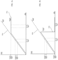
- FIGs. 3a and 3b depict graphs illustrating an input voltage and output voltage based on the configuration of a lightning circuit according to one or more embodiments.
- FIG. 3a provides the exemplary graph for a lightning circuit that clips the output voltage at a preset level.
- the dashed line 302a depicts the input voltage and the solid line 304a depicts the output voltage.
- the input voltage is supplied from a test signal source 220 (from FIG. 2 ) and the output voltage is measured at an output of the LRU 200 (from FIG. 2 ).
- the output voltage 304a clips (i.e., flattens out) when the input voltage hits a threshold voltage.
- FIG. 3b provides an exemplary graph for a lighting circuit that cuts off the output voltage at a preset level.
- the dashed line 302b depicts the input voltage and the solid line 304b depicts the output voltage.
- the input voltage is supplied from a test signal source 220 (from FIG. 2 ) and the output voltage is measured at an output of the LRU 200 (from FIG. 2 ).
- the output voltage 304b cuts off and is driven to preset level when a threshold input voltage is hit.
- one or more embodiments for testing the LRU 200 (from FIG. 2 ) the two filters are difficult to test due to the lightning protection circuit either cutting off or clipping the input voltage signal to the LRU as described in FIGs. 3a and 3b .
- one or more embodiments supply a DC bias voltage that is added to a small test signal supplied to the LRU.
- the LRU may be referred to as the Unit Under Test (UUT) or Circuit Under Test hereafter.
- the impedance measured and its response when the lightning circuit is "ON” is the combination of all the circuits in the circuit under test (i.e., HIRF filter, EMI filter, and lightning protection circuit).
- the lightning circuit is effectively "OFF” for this small test signal.
- the impedance measured would be for the circuits that are before the lightning protection circuit because the test signal would not pass the output side of the lightning protection circuit.
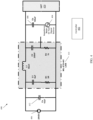
- FIG. 4 depicts a diagram of a testing system for a lightning protection circuit according to one or more embodiments.
- the testing system 400 includes a test signal source 404 or impedance meter.
- the test signal source can be an AC voltage source that injects the test signal and the impedance meter can be an AC current meter for the response. The injected voltage is divided by the measured current to get the impedance value.
- an impedance meter can replace the voltage source and current meter. The impedance meter works by injecting either a voltage (or current) and measuring current (or voltage) then dividing the two numbers to display an impedance reading all carried out within the same instrument.
- This testing system 400 can be attached to an input of a unit under test (UUT) 420 (sometimes referred to as a circuit under test).
- the UUT is the LRU 200 (from FIG. 2 ).
- the system 400 includes a DC bias voltage source 406 that is configured to supply/provide a DC bias voltage for the system 400.
- the test signal source 404 is configured to supply a small testing signal that is an alternating current (AC) test signal to the UUT 420.
- a first capacitor Cb 408 is included to couple the test signal source 404 to the test system 400 and to keep the DC bias from the test signal source 404.
- the capacitance for this first capacitor is at least 100 ⁇ F.
- the system 400 also includes a line impedance stabilizing network (LISN) 410 that is utilized to minimize the amount of signal current to the DC bias source 406.
- LISN line impedance stabilizing network
- a LISN is a low-pass filter typically placed between an AC or DC power source and the EUT (equipment under test) to create a known impedance and to provide a radio frequency (RF) noise measurement port. It also isolates any unwanted RF signals from the power source.
- the system 400 optionally, includes a second capacitor Cs 412 to further reduce the effect of the DC bias source 406 characteristic on the test results.
- the system 400 also includes a controller 402 that is configured to operate any and all of the components in the system 400.
- the controller 402 or any of the hardware referenced in the system 400 can be implemented by executable instructions and/or circuitry such as a processing circuit and memory.
- the processing circuit can be embodied in any type of central processing unit (CPU), including a microprocessor, a digital signal processor (DSP), a microcontroller, an application specific integrated circuit (ASIC), a field programmable gate array (FPGA), or the like.
- the memory may include random access memory (RAM), read only memory (ROM), or other electronic, optical, magnetic, or any other computer readable medium onto which is stored data and algorithms as executable instructions in a non-transitory form.
- the controller 402 is configured to operate the test signal source 404 to supply an AC testing signal for the UUT 420.
- the controller 402 is further configured to operate/control the DC bias source 406 to provide a DC bias voltage for the UUT 420.
- the controller 402 can receive impedance measurements from the test signal source 404 for processing to determine the impedance for the UUT 420.
- the DC bias and small testing signal are supplied to the UUT 420 to test the components that include an HIRF filter, a lightning protection circuit, and an EMI filter.
- the HIRF filter is to the left of the lightning protection circuit, so any combination of test signal and DC bias voltage that has a voltage above the threshold voltage for the lighting protection circuit will shut off the lightning protection circuit and the impedance measured will be from just the HIRF filter in the UUT 420.
- the impedance measurement is taken for the entire UUT 420.
- the controller 402 can utilize these impedance measurements to determine if any faults exist in the UUT 420 and further determine what type of fault exists. The determination of the existence of the fault can be based on a comparison of plotted impedance values tested at different frequencies to plotted impedance values for known components operating normally.
- the different frequencies for testing can include 3.5kHz, 100kHz, and 250kHz which produce impedance values that can be plotted and compared to the plotted values of normal operating components. Any deviations observed between the plots can indicate a defective filter component either before or after the lightning switch depending on the DC bias.
- FIG. 5 depicts a diagram of a testing system for a lightning protection circuit according to one or more embodiments.
- the testing system 500 includes a test signal source 504 or impedance meter.
- the test signal source 504 is coupled to an injection transformer 510.
- the testing system 500 is attached to an input of a unit under test (UUT) 520 and configured to supply testing AC signals along with a DC bias voltage.
- the UUT 520 includes a lightning protection circuit along with a HIRF filter and an EMI filter.
- the system 500 includes a DC bias voltage source 506 that is configured to supply/provide a DC bias voltage for the testing system 500.
- the system 500 also includes a first capacitor Cs 512 and a controller 502.
- controller 502 is configured to operate any and all of the components in the system 500.
- the controller 502 or any of the hardware referenced in the system 500 can be implemented by executable instructions and/or circuitry such as a processing circuit and memory.
- the processing circuit can be embodied in any type of central processing unit (CPU), including a microprocessor, a digital signal processor (DSP), a microcontroller, an application specific integrated circuit (ASIC), a field programmable gate array (FPGA), or the like.
- the memory may include random access memory (RAM), read only memory (ROM), or other electronic, optical, magnetic, or any other computer readable medium onto which is stored data and algorithms as executable instructions in a non-transitory form.
- the controller 502 is configured to operate the test signal source 504 and the DC bias voltage supply 506 to supply a test signal to the UUT 520 which will either have a voltage that is below or is above the threshold voltage of the lightning protection circuit. Based on this, the testing signal source 504 can measure an impedance value for the UUT 520 in both cases. When the voltage is above the threshold voltage, the impedance value will be a measure of just the circuits before the lightning protection circuit because the lightning protection circuit will be turned off.
- the circuits before the lightning protection circuit can be, for example, an HIRF filter.
- the injection transformer 510 is similar to a current transformer (CT) in the form of a donut shaped core with a secondary winding.
- CT current transformer
- the DC power cable feeds through the donut to form a one-turn primary winding.
- the test signal voltage can be added to the 28V DC source (i.e., in series, but a load current is not ideal).
- the injection transformer 510 is utilized to separate the high current from the test signal source 504.
- FIG. 6 depicts a flow diagram of a method for testing lightning protection circuits according to one or more embodiments.
- the method 600 includes providing an alternating current (AC) test signal source coupled to a circuit under test, wherein the circuit under test including a lightning protection circuit having a threshold voltage, a first filter, and a second filter, as shown in block 602.
- the circuit under test includes the lightning protection circuit between the first filter and second filter which correspond to an HIRF filter and EMI filter, respectively.
- the method 600 continues by providing a direct current (DC) voltage supply in series with a filtering device, the filtering device coupled to the AC test signal source.
- the filter device can be a LISN as described in FIG. 4 .
- the method 600 also includes providing a first capacitor coupled between the AC test signal source and the circuit under test.
- the capacitor blocks the effects of the DC power supply bias voltage.
- the method 600 at block 608 also includes operating, by a controller, the DC voltage supply and the AC test signal source to provide a first test signal to the circuit under test, wherein the first test signal comprise a first voltage that exceeds the threshold voltage.
- the method 600 includes measuring, by the controller, a first impedance of the circuit under test responsive to providing the first test signal to the circuit under test, wherein the first impedance corresponds to the first filter.
Landscapes
- Physics & Mathematics (AREA)
- General Physics & Mathematics (AREA)
- Engineering & Computer Science (AREA)
- Power Engineering (AREA)
- General Engineering & Computer Science (AREA)
- Emergency Protection Circuit Devices (AREA)
Claims (15)
- System (400; 500), umfassend:eine Wechselstrom-Prüfsignalquelle (404; 504), die zum Koppeln an eine zu prüfende Schaltung (420; 520) konfiguriert ist, wobei die zu prüfende Schaltung eine Blitzschutzschaltung (202), die eine Schwellenspannung aufweist, ein erstes Filter (212) und ein zweites Filter (210) umfasst;eine Gleichstrom-Spannungsversorgung (406; 506) in Reihe mit einer Filtervorrichtung (410; 510), wobei die Filtervorrichtung an die Wechselstrom-Prüfsignalquelle gekoppelt ist;einen ersten Kondensator (408), der an die Wechselstrom-Prüfsignalquelle gekoppelt und zum Koppeln zwischen der Wechselstrom-Prüfsignalquelle und der zu prüfende Schaltung konfiguriert ist;eine Steuerung (402), die zu Folgendem konfiguriert ist:
Betreiben der Gleichspannungsversorgung und der Wechselstrom-Prüfsignalquelle zum Bereitstellen eines ersten Prüfsignals an der zu prüfenden Schaltung, wobei das erste Prüfsignal eine erste Spannung umfasst, die die Schwellenspannung überschreitet; Messen einer ersten Impedanz der zu prüfenden Schaltung als Reaktion auf das Bereitstellen des ersten Prüfsignals an der zu prüfenden Schaltung, wobei die erste Impedanz dem ersten Filter entspricht. - System (400; 500) nach Anspruch 1, wobei die Steuerung ferner zu Folgendem konfiguriert ist:Betreiben der Gleichspannungsversorgung (406; 506) und der Wechselstrom-Prüfsignalquelle (404; 504) zum Bereitstellen eines zweiten Prüfsignals an der zu prüfenden Schaltung (420; 520), wobei das zweite Prüfsignal eine zweite Spannung umfasst, die unterhalb der Schwellenspannung liegt;Messen einer zweiten Impedanz der zu prüfenden Schaltung als Reaktion auf das Bereitstellen des zweiten Prüfsignals an der zu prüfenden Schaltung, wobei die zweite Impedanz dem ersten Filter (212), dem Blitzschutzschaltkreis (202) und dem zweiten Filter (210) entspricht; undBestimmen von mindestens einem Fehler der zu prüfenden Schaltung basierend auf der ersten Impedanz und der zweiten Impedanz.
- System (400; 500) nach Anspruch 1 oder 2, wobei die Blitzschutzschaltung (202) in Reihe zwischen dem ersten Filter (212) und dem zweiten Filter (210) liegt.
- System (400; 500) nach einem der vorhergehenden Ansprüche, wobei das erste Filter (212) zum Näherliegen an einem externen Eingang der zu prüfenden Schaltung (420; 520) als das zweite Filter (210) konfiguriert ist.
- System (400; 500) nach einem der vorhergehenden Ansprüche, wobei die Blitzschutzschaltung (202) zum Blockieren des ersten Prüfsignals basierend auf dem Überschreiten der Schwellenspannung durch die erste Spannung konfiguriert ist.
- Verfahren (600), umfassendBereitstellen einer Wechselstrom-Prüfsignalquelle (404; 504), die zum Koppeln an die zu prüfende Schaltung (420; 520) konfiguriert ist, wobei die zu prüfende Schaltung eine Blitzschutzschaltung (202), die eine Schwellenspannung aufweist, ein erstes Filter (212) und ein zweites Filter (210) umfasst;Bereitstellen einer Gleichstrom-Spannungsversorgung (406; 506) in Reihe mit einer Filtervorrichtung (410; 510), wobei die Filtervorrichtung an die Wechselstrom-Prüfsignalquelle gekoppelt ist;Bereitstellen eines ersten Kondensators (408), der an die Wechselstrom-Prüfsignalquelle gekoppelt und zum Koppeln zwischen der Wechselstrom-Prüfsignalquelle und der zu prüfende Schaltung konfiguriert ist;Betreiben der Gleichspannungsversorgung und der Wechselstrom-Prüfsignalquelle durch eine Steuerung (402) zum Bereitstellen eines ersten Prüfsignals an der zu prüfenden Schaltung, wobei das erste Prüfsignal eine erste Spannung umfasst, die die Schwellenspannung überschreitet;Messen einer ersten Impedanz der zu prüfenden Schaltung durch die Steuerung als Reaktion auf das Bereitstellen des ersten Prüfsignals an der zu prüfenden Schaltung, wobei die erste Impedanz dem ersten Filter entspricht.
- Verfahren (600) nach Anspruch 6, ferner umfassend:Betreiben der Gleichspannungsversorgung (406; 506) und der Wechselstrom-Prüfsignalquelle (404; 504) durch die Steuerung (402) zum Bereitstellen eines zweiten Prüfsignals an der zu prüfenden Schaltung (420; 520), wobei das zweite Prüfsignal eine zweite Spannung umfasst, die unterhalb der Schwellenspannung liegt;Messen einer zweiten Impedanz der zu prüfenden Schaltung durch die Steuerung als Reaktion auf das Bereitstellen des zweiten Prüfsignals an der zu prüfenden Schaltung, wobei die zweite Impedanz dem ersten Filter (212), dem Blitzschutzschaltkreis (202) und dem zweiten Filter (210) entspricht; undBestimmen von mindestens einem Fehler der zu prüfenden Schaltung durch die Steuerung basierend auf der ersten Impedanz und der zweiten Impedanz.
- Verfahren (600) nach Anspruch 6 oder 7, wobei die Blitzschutzschaltung (202) in Reihe zwischen dem ersten Filter (212) und dem zweiten Filter (210) liegt.
- Verfahren (600) nach einem der Ansprüche 6 bis 8, wobei das erste Filter (212) zum Näherliegen an einem externen Eingang der zu prüfenden Schaltung (420; 520) als das zweite Filter (210) konfiguriert ist.
- Verfahren (600) nach einem der Ansprüche 6 bis 9, wobei die Blitzschutzschaltung (202) zum Blockieren des ersten Prüfsignals basierend auf dem Überschreiten der Schwellenspannung durch die erste Spannung konfiguriert ist.
- System (400; 500) nach einem der Ansprüche 1 bis 4 oder Verfahren (600) nach einem der Ansprüche 6 bis 9, wobei die Blitzschutzschaltung (202) zum Begrenzen des ersten Prüfsignals basierend auf dem Überschreiten der Schwellenspannung durch die erste Spannung konfiguriert ist.
- System (400) nach einem der Ansprüche 1 bis 5 oder 11 oder Verfahren (600) nach einem der Ansprüche 6 bis 11, wobei die Filtervorrichtung (410) ein Leitungsimpedanzstabilisierungsnetzwerk, LISN, umfasst.
- System (400; 500) nach einem der Ansprüche 1 bis 5, 11 oder 12 oder Verfahren nach einem der Ansprüche 6 bis 12, wobei das erste Filter (212) ein Filter für ein Hochintensiv-Strahlungsfeld, HIRF, umfasst.
- System (400; 500) nach einem der Ansprüche 1 bis 5 oder 11 bis 13 oder Verfahren (600) nach einem der Ansprüche 6 bis 13, wobei das zweite Filter (210) ein Filter für elektromagnetische Interferenzen, EMI, umfasst.
- System (400; 500) nach einem der Ansprüche 1 bis 5 oder 11 bis 14 oder Verfahren (600) nach einem der Ansprüche 6 bis 14, wobei der erste Kondensator (408) eine Kapazität von mindestens 100 Mikrofarad aufweist.
Applications Claiming Priority (1)
| Application Number | Priority Date | Filing Date | Title |
|---|---|---|---|
| US17/411,258 US11879931B2 (en) | 2021-08-25 | 2021-08-25 | Circuit testing and diagnosis |
Publications (2)
| Publication Number | Publication Date |
|---|---|
| EP4145145A1 EP4145145A1 (de) | 2023-03-08 |
| EP4145145B1 true EP4145145B1 (de) | 2024-12-18 |
Family
ID=83081206
Family Applications (1)
| Application Number | Title | Priority Date | Filing Date |
|---|---|---|---|
| EP22192233.9A Active EP4145145B1 (de) | 2021-08-25 | 2022-08-25 | Schaltungsprüfung und -diagnose |
Country Status (2)
| Country | Link |
|---|---|
| US (1) | US11879931B2 (de) |
| EP (1) | EP4145145B1 (de) |
Families Citing this family (4)
| Publication number | Priority date | Publication date | Assignee | Title |
|---|---|---|---|---|
| US11879931B2 (en) * | 2021-08-25 | 2024-01-23 | Hamilton Sundstrand Corporation | Circuit testing and diagnosis |
| US12415601B2 (en) * | 2022-11-29 | 2025-09-16 | Textron Innovations Inc. | Electrically isolated auxiliary flight controllers for rotorcraft |
| US20250392207A1 (en) * | 2024-06-24 | 2025-12-25 | Honeywell International Inc. | Active pre-charge circuit for avionics lrus |
| CN120741999B (zh) * | 2025-08-22 | 2025-11-14 | 合肥航太电物理技术有限公司 | 一种雷电与hirf系统级综合效应试验装置及方法 |
Family Cites Families (19)
| Publication number | Priority date | Publication date | Assignee | Title |
|---|---|---|---|---|
| DE2125810C3 (de) | 1970-11-25 | 1979-11-22 | Veb Transformatoren- Und Roentgenwerk Hermann Matern, Ddr 8030 Dresden | Schaltungsanordnung für eine Priifanlage |
| GB2038490B (en) * | 1978-12-21 | 1983-02-09 | Measurement Tech Ltd | Electrical circuit testing |
| JPH0554744A (ja) | 1991-08-28 | 1993-03-05 | Ngk Insulators Ltd | 避雷碍子の劣化診断方法 |
| US20030156367A1 (en) * | 2002-02-01 | 2003-08-21 | Macbeth Bruce F. | Arc fault circuit interrupter with upstream impedance detector |
| KR100720965B1 (ko) * | 2006-06-27 | 2007-05-23 | 박영진 | 차단 주파수 조절이 가능한 전자파 차폐 필터 |
| TW201134048A (en) * | 2010-03-30 | 2011-10-01 | Hon Hai Prec Ind Co Ltd | Electronic device |
| US8841898B2 (en) * | 2011-10-25 | 2014-09-23 | The Boeing Company | Method and apparatus for detecting a lightning strike |
| US8994391B2 (en) * | 2012-04-25 | 2015-03-31 | Bae Systems Controls Inc. | Internal line replaceable unit high intensity radiated field detector |
| US9128119B2 (en) * | 2013-03-29 | 2015-09-08 | Hamilton Sundstrand Corporation | Electrical circuit testing |
| US9383405B2 (en) * | 2013-04-10 | 2016-07-05 | Hamilton Sundstrand Corporation | Transient voltage suppression protection circuit including built in testing |
| CN106786460A (zh) * | 2016-12-29 | 2017-05-31 | 康迎利 | 防雷模块 |
| FR3073283B1 (fr) * | 2017-11-03 | 2019-11-15 | Safran Electronics & Defense | Dispositif de protection contre la foudre ameliore pour une entree differentielle |
| FR3075518B1 (fr) * | 2017-12-18 | 2021-01-29 | Safran Electronics & Defense | Circuit de commutation |
| CN110146794A (zh) | 2019-05-28 | 2019-08-20 | 国网江苏省电力有限公司电力科学研究院 | 多电压叠加下gis/gil耐压及局部放电试验方法及装置 |
| CN112415352A (zh) | 2021-01-22 | 2021-02-26 | 杭州富特科技股份有限公司 | 基于逆变器的在线绝缘检测电路以及逆变器系统 |
| CN115219807A (zh) * | 2021-04-20 | 2022-10-21 | 上海铁路通信有限公司 | 防雷测试与绝缘测试兼容电路及电子设备 |
| CN113125916A (zh) * | 2021-04-25 | 2021-07-16 | 西安交通大学 | 一种直流叠加冲击的避雷器试验装置 |
| US11879931B2 (en) * | 2021-08-25 | 2024-01-23 | Hamilton Sundstrand Corporation | Circuit testing and diagnosis |
| CN114204536A (zh) * | 2021-12-31 | 2022-03-18 | 陶显芳 | 一种带防雷功能的单相电源插头座 |
-
2021
- 2021-08-25 US US17/411,258 patent/US11879931B2/en active Active
-
2022
- 2022-08-25 EP EP22192233.9A patent/EP4145145B1/de active Active
Also Published As
| Publication number | Publication date |
|---|---|
| EP4145145A1 (de) | 2023-03-08 |
| US20230064503A1 (en) | 2023-03-02 |
| US11879931B2 (en) | 2024-01-23 |
Similar Documents
| Publication | Publication Date | Title |
|---|---|---|
| EP4145145B1 (de) | Schaltungsprüfung und -diagnose | |
| US10931096B2 (en) | Systems and methods for actuating a transformer neutral blocking system | |
| US8537508B2 (en) | Sensing and control electronics for a power grid protection system | |
| US8878396B2 (en) | Continuous uninterruptable AC grounding system for power system protection | |
| US10903640B2 (en) | Electrical link comprising an electrical protection device | |
| KR101438120B1 (ko) | Hemp 대책용 전원선로 방호장치 | |
| Shankar Tiwari et al. | Design and analysis of an over current relay based on matlab/simulink environment | |
| Sauvage et al. | New concept using Silicon Carbide current limiter device for lightning surge protection of embedded aircraft equipment | |
| US12306268B2 (en) | Health monitoring in electric motor control systems | |
| Hoshino et al. | Proposal of HEMP Conducted Disturbance Test Method for Semi-Conductor Protective Devices on Electronic Circuit | |
| Longoria | Validating the HEMP Protection Capabilities of Power Filters | |
| Binqin et al. | Research on Test Characteristics of Nuclear Power Plant Instrument and Control Equipment CS116 | |
| Wang | Electromagnetic Compatibility Design for Mobile Target Positioning Terminals | |
| Zhou et al. | Surge immunity test of personal computer at power lines | |
| BR112020013897B1 (pt) | Sistema e método para supressão em sistemas elétricos desobretensões induzidas por pulso eletromagnético | |
| HK1186005B (en) | Sensing and control electronics for a power grid protection system | |
| HK1186006B (en) | Continuous uninterruptable ac grounding system for power system protection |
Legal Events
| Date | Code | Title | Description |
|---|---|---|---|
| PUAI | Public reference made under article 153(3) epc to a published international application that has entered the european phase |
Free format text: ORIGINAL CODE: 0009012 |
|
| STAA | Information on the status of an ep patent application or granted ep patent |
Free format text: STATUS: THE APPLICATION HAS BEEN PUBLISHED |
|
| AK | Designated contracting states |
Kind code of ref document: A1 Designated state(s): AL AT BE BG CH CY CZ DE DK EE ES FI FR GB GR HR HU IE IS IT LI LT LU LV MC MK MT NL NO PL PT RO RS SE SI SK SM TR |
|
| STAA | Information on the status of an ep patent application or granted ep patent |
Free format text: STATUS: REQUEST FOR EXAMINATION WAS MADE |
|
| 17P | Request for examination filed |
Effective date: 20230906 |
|
| RBV | Designated contracting states (corrected) |
Designated state(s): AL AT BE BG CH CY CZ DE DK EE ES FI FR GB GR HR HU IE IS IT LI LT LU LV MC MK MT NL NO PL PT RO RS SE SI SK SM TR |
|
| GRAP | Despatch of communication of intention to grant a patent |
Free format text: ORIGINAL CODE: EPIDOSNIGR1 |
|
| STAA | Information on the status of an ep patent application or granted ep patent |
Free format text: STATUS: GRANT OF PATENT IS INTENDED |
|
| INTG | Intention to grant announced |
Effective date: 20240313 |
|
| GRAJ | Information related to disapproval of communication of intention to grant by the applicant or resumption of examination proceedings by the epo deleted |
Free format text: ORIGINAL CODE: EPIDOSDIGR1 |
|
| STAA | Information on the status of an ep patent application or granted ep patent |
Free format text: STATUS: REQUEST FOR EXAMINATION WAS MADE |
|
| GRAP | Despatch of communication of intention to grant a patent |
Free format text: ORIGINAL CODE: EPIDOSNIGR1 |
|
| STAA | Information on the status of an ep patent application or granted ep patent |
Free format text: STATUS: GRANT OF PATENT IS INTENDED |
|
| INTC | Intention to grant announced (deleted) | ||
| INTG | Intention to grant announced |
Effective date: 20240716 |
|
| GRAS | Grant fee paid |
Free format text: ORIGINAL CODE: EPIDOSNIGR3 |
|
| GRAA | (expected) grant |
Free format text: ORIGINAL CODE: 0009210 |
|
| STAA | Information on the status of an ep patent application or granted ep patent |
Free format text: STATUS: THE PATENT HAS BEEN GRANTED |
|
| AK | Designated contracting states |
Kind code of ref document: B1 Designated state(s): AL AT BE BG CH CY CZ DE DK EE ES FI FR GB GR HR HU IE IS IT LI LT LU LV MC MK MT NL NO PL PT RO RS SE SI SK SM TR |
|
| REG | Reference to a national code |
Ref country code: CH Ref legal event code: EP |
|
| REG | Reference to a national code |
Ref country code: DE Ref legal event code: R096 Ref document number: 602022008791 Country of ref document: DE |
|
| REG | Reference to a national code |
Ref country code: IE Ref legal event code: FG4D |
|
| REG | Reference to a national code |
Ref country code: LT Ref legal event code: MG9D |
|
| PG25 | Lapsed in a contracting state [announced via postgrant information from national office to epo] |
Ref country code: HR Free format text: LAPSE BECAUSE OF FAILURE TO SUBMIT A TRANSLATION OF THE DESCRIPTION OR TO PAY THE FEE WITHIN THE PRESCRIBED TIME-LIMIT Effective date: 20241218 |
|
| PG25 | Lapsed in a contracting state [announced via postgrant information from national office to epo] |
Ref country code: FI Free format text: LAPSE BECAUSE OF FAILURE TO SUBMIT A TRANSLATION OF THE DESCRIPTION OR TO PAY THE FEE WITHIN THE PRESCRIBED TIME-LIMIT Effective date: 20241218 |
|
| PG25 | Lapsed in a contracting state [announced via postgrant information from national office to epo] |
Ref country code: BG Free format text: LAPSE BECAUSE OF FAILURE TO SUBMIT A TRANSLATION OF THE DESCRIPTION OR TO PAY THE FEE WITHIN THE PRESCRIBED TIME-LIMIT Effective date: 20241218 |
|
| PG25 | Lapsed in a contracting state [announced via postgrant information from national office to epo] |
Ref country code: NO Free format text: LAPSE BECAUSE OF FAILURE TO SUBMIT A TRANSLATION OF THE DESCRIPTION OR TO PAY THE FEE WITHIN THE PRESCRIBED TIME-LIMIT Effective date: 20250318 |
|
| REG | Reference to a national code |
Ref country code: NL Ref legal event code: MP Effective date: 20241218 |
|
| PG25 | Lapsed in a contracting state [announced via postgrant information from national office to epo] |
Ref country code: GR Free format text: LAPSE BECAUSE OF FAILURE TO SUBMIT A TRANSLATION OF THE DESCRIPTION OR TO PAY THE FEE WITHIN THE PRESCRIBED TIME-LIMIT Effective date: 20250319 Ref country code: LV Free format text: LAPSE BECAUSE OF FAILURE TO SUBMIT A TRANSLATION OF THE DESCRIPTION OR TO PAY THE FEE WITHIN THE PRESCRIBED TIME-LIMIT Effective date: 20241218 |
|
| PG25 | Lapsed in a contracting state [announced via postgrant information from national office to epo] |
Ref country code: RS Free format text: LAPSE BECAUSE OF FAILURE TO SUBMIT A TRANSLATION OF THE DESCRIPTION OR TO PAY THE FEE WITHIN THE PRESCRIBED TIME-LIMIT Effective date: 20250318 |
|
| PG25 | Lapsed in a contracting state [announced via postgrant information from national office to epo] |
Ref country code: NL Free format text: LAPSE BECAUSE OF FAILURE TO SUBMIT A TRANSLATION OF THE DESCRIPTION OR TO PAY THE FEE WITHIN THE PRESCRIBED TIME-LIMIT Effective date: 20241218 |
|
| REG | Reference to a national code |
Ref country code: AT Ref legal event code: MK05 Ref document number: 1752636 Country of ref document: AT Kind code of ref document: T Effective date: 20241218 |
|
| PG25 | Lapsed in a contracting state [announced via postgrant information from national office to epo] |
Ref country code: SM Free format text: LAPSE BECAUSE OF FAILURE TO SUBMIT A TRANSLATION OF THE DESCRIPTION OR TO PAY THE FEE WITHIN THE PRESCRIBED TIME-LIMIT Effective date: 20241218 |
|
| PG25 | Lapsed in a contracting state [announced via postgrant information from national office to epo] |
Ref country code: PL Free format text: LAPSE BECAUSE OF FAILURE TO SUBMIT A TRANSLATION OF THE DESCRIPTION OR TO PAY THE FEE WITHIN THE PRESCRIBED TIME-LIMIT Effective date: 20241218 |
|
| PG25 | Lapsed in a contracting state [announced via postgrant information from national office to epo] |
Ref country code: ES Free format text: LAPSE BECAUSE OF FAILURE TO SUBMIT A TRANSLATION OF THE DESCRIPTION OR TO PAY THE FEE WITHIN THE PRESCRIBED TIME-LIMIT Effective date: 20241218 |
|
| PG25 | Lapsed in a contracting state [announced via postgrant information from national office to epo] |
Ref country code: IS Free format text: LAPSE BECAUSE OF FAILURE TO SUBMIT A TRANSLATION OF THE DESCRIPTION OR TO PAY THE FEE WITHIN THE PRESCRIBED TIME-LIMIT Effective date: 20250418 |
|
| PG25 | Lapsed in a contracting state [announced via postgrant information from national office to epo] |
Ref country code: PT Free format text: LAPSE BECAUSE OF FAILURE TO SUBMIT A TRANSLATION OF THE DESCRIPTION OR TO PAY THE FEE WITHIN THE PRESCRIBED TIME-LIMIT Effective date: 20250421 |
|
| PG25 | Lapsed in a contracting state [announced via postgrant information from national office to epo] |
Ref country code: EE Free format text: LAPSE BECAUSE OF FAILURE TO SUBMIT A TRANSLATION OF THE DESCRIPTION OR TO PAY THE FEE WITHIN THE PRESCRIBED TIME-LIMIT Effective date: 20241218 |
|
| PG25 | Lapsed in a contracting state [announced via postgrant information from national office to epo] |
Ref country code: AT Free format text: LAPSE BECAUSE OF FAILURE TO SUBMIT A TRANSLATION OF THE DESCRIPTION OR TO PAY THE FEE WITHIN THE PRESCRIBED TIME-LIMIT Effective date: 20241218 Ref country code: RO Free format text: LAPSE BECAUSE OF FAILURE TO SUBMIT A TRANSLATION OF THE DESCRIPTION OR TO PAY THE FEE WITHIN THE PRESCRIBED TIME-LIMIT Effective date: 20241218 |
|
| PG25 | Lapsed in a contracting state [announced via postgrant information from national office to epo] |
Ref country code: SK Free format text: LAPSE BECAUSE OF FAILURE TO SUBMIT A TRANSLATION OF THE DESCRIPTION OR TO PAY THE FEE WITHIN THE PRESCRIBED TIME-LIMIT Effective date: 20241218 |
|
| PG25 | Lapsed in a contracting state [announced via postgrant information from national office to epo] |
Ref country code: CZ Free format text: LAPSE BECAUSE OF FAILURE TO SUBMIT A TRANSLATION OF THE DESCRIPTION OR TO PAY THE FEE WITHIN THE PRESCRIBED TIME-LIMIT Effective date: 20241218 |
|
| PG25 | Lapsed in a contracting state [announced via postgrant information from national office to epo] |
Ref country code: IT Free format text: LAPSE BECAUSE OF FAILURE TO SUBMIT A TRANSLATION OF THE DESCRIPTION OR TO PAY THE FEE WITHIN THE PRESCRIBED TIME-LIMIT Effective date: 20241218 |
|
| PG25 | Lapsed in a contracting state [announced via postgrant information from national office to epo] |
Ref country code: SE Free format text: LAPSE BECAUSE OF FAILURE TO SUBMIT A TRANSLATION OF THE DESCRIPTION OR TO PAY THE FEE WITHIN THE PRESCRIBED TIME-LIMIT Effective date: 20241218 |
|
| REG | Reference to a national code |
Ref country code: DE Ref legal event code: R097 Ref document number: 602022008791 Country of ref document: DE |
|
| PG25 | Lapsed in a contracting state [announced via postgrant information from national office to epo] |
Ref country code: DK Free format text: LAPSE BECAUSE OF FAILURE TO SUBMIT A TRANSLATION OF THE DESCRIPTION OR TO PAY THE FEE WITHIN THE PRESCRIBED TIME-LIMIT Effective date: 20241218 |
|
| PGFP | Annual fee paid to national office [announced via postgrant information from national office to epo] |
Ref country code: DE Payment date: 20250724 Year of fee payment: 4 |
|
| PGFP | Annual fee paid to national office [announced via postgrant information from national office to epo] |
Ref country code: FR Payment date: 20250723 Year of fee payment: 4 |
|
| PLBE | No opposition filed within time limit |
Free format text: ORIGINAL CODE: 0009261 |
|
| STAA | Information on the status of an ep patent application or granted ep patent |
Free format text: STATUS: NO OPPOSITION FILED WITHIN TIME LIMIT |
|
| REG | Reference to a national code |
Ref country code: CH Ref legal event code: L10 Free format text: ST27 STATUS EVENT CODE: U-0-0-L10-L00 (AS PROVIDED BY THE NATIONAL OFFICE) Effective date: 20251029 |
|
| 26N | No opposition filed |
Effective date: 20250919 |
|
| REG | Reference to a national code |
Ref country code: CH Ref legal event code: H13 Free format text: ST27 STATUS EVENT CODE: U-0-0-H10-H13 (AS PROVIDED BY THE NATIONAL OFFICE) Effective date: 20260324 |
|
| PG25 | Lapsed in a contracting state [announced via postgrant information from national office to epo] |
Ref country code: MC Free format text: LAPSE BECAUSE OF FAILURE TO SUBMIT A TRANSLATION OF THE DESCRIPTION OR TO PAY THE FEE WITHIN THE PRESCRIBED TIME-LIMIT Effective date: 20241218 |
|
| PG25 | Lapsed in a contracting state [announced via postgrant information from national office to epo] |
Ref country code: LU Free format text: LAPSE BECAUSE OF NON-PAYMENT OF DUE FEES Effective date: 20250825 |
|
| PG25 | Lapsed in a contracting state [announced via postgrant information from national office to epo] |
Ref country code: CH Free format text: LAPSE BECAUSE OF NON-PAYMENT OF DUE FEES Effective date: 20250831 |