EP4144545A1 - Dividing wall mounting device - Google Patents
Dividing wall mounting device Download PDFInfo
- Publication number
- EP4144545A1 EP4144545A1 EP21855787.4A EP21855787A EP4144545A1 EP 4144545 A1 EP4144545 A1 EP 4144545A1 EP 21855787 A EP21855787 A EP 21855787A EP 4144545 A1 EP4144545 A1 EP 4144545A1
- Authority
- EP
- European Patent Office
- Prior art keywords
- dividing wall
- end side
- mounting device
- hole
- wall mounting
- Prior art date
- Legal status (The legal status is an assumption and is not a legal conclusion. Google has not performed a legal analysis and makes no representation as to the accuracy of the status listed.)
- Withdrawn
Links
- 229920001971 elastomer Polymers 0.000 claims abstract description 7
- 239000000806 elastomer Substances 0.000 claims abstract description 7
- 238000003780 insertion Methods 0.000 claims abstract description 5
- 230000037431 insertion Effects 0.000 claims abstract description 5
- 239000012530 fluid Substances 0.000 claims description 7
- 239000002184 metal Substances 0.000 claims description 3
- 239000011347 resin Substances 0.000 claims description 2
- 229920005989 resin Polymers 0.000 claims description 2
- 239000004636 vulcanized rubber Substances 0.000 description 4
- 230000006835 compression Effects 0.000 description 3
- 238000007906 compression Methods 0.000 description 3
- 230000001133 acceleration Effects 0.000 description 2
- 230000007423 decrease Effects 0.000 description 2
- 238000001514 detection method Methods 0.000 description 2
- 238000005516 engineering process Methods 0.000 description 2
- 238000012856 packing Methods 0.000 description 2
- 239000000853 adhesive Substances 0.000 description 1
- 230000001070 adhesive effect Effects 0.000 description 1
- 230000008878 coupling Effects 0.000 description 1
- 238000010168 coupling process Methods 0.000 description 1
- 238000005859 coupling reaction Methods 0.000 description 1
- 230000000694 effects Effects 0.000 description 1
- 238000000034 method Methods 0.000 description 1
- 238000000465 moulding Methods 0.000 description 1
Images





Classifications
-
- B—PERFORMING OPERATIONS; TRANSPORTING
- B60—VEHICLES IN GENERAL
- B60C—VEHICLE TYRES; TYRE INFLATION; TYRE CHANGING; CONNECTING VALVES TO INFLATABLE ELASTIC BODIES IN GENERAL; DEVICES OR ARRANGEMENTS RELATED TO TYRES
- B60C29/00—Arrangements of tyre-inflating valves to tyres or rims; Accessories for tyre-inflating valves, not otherwise provided for
- B60C29/02—Connection to rims
-
- B—PERFORMING OPERATIONS; TRANSPORTING
- B60—VEHICLES IN GENERAL
- B60C—VEHICLE TYRES; TYRE INFLATION; TYRE CHANGING; CONNECTING VALVES TO INFLATABLE ELASTIC BODIES IN GENERAL; DEVICES OR ARRANGEMENTS RELATED TO TYRES
- B60C29/00—Arrangements of tyre-inflating valves to tyres or rims; Accessories for tyre-inflating valves, not otherwise provided for
- B60C29/005—Arrangements of tyre-inflating valves to tyres or rims; Accessories for tyre-inflating valves, not otherwise provided for characterised by particular features of the valve stem
Definitions
- the present disclosure relates to a dividing wall mounting device attached to a through-hole of a dividing wall that separates an inner region from the outside.
- dividing wall mounting device for example, a dividing wall mounting device that is press-fitted into a through-hole of a rim of a wheel corresponding to a dividing wall, such as a snap-in type tire valve, is known (see, for example, Patent Document 1).
- Patent Document 1 JP 2012-91568 A ( Fig. 2 )
- the conventional dividing wall mounting device needs to be press-fitted into the through-hole from an inner side that is a high pressure side with respect to the dividing wall, and it takes time and effort to attach the dividing wall mounting device.
- the above-described tire valve needs to be press-fitted into the through-hole from the inner region side of the tire, which is the high pressure side with respect to the rim serving as the dividing wall, there is a problem in that it takes time and effort to remove the tire from the wheel whenever replacing the tire valve.
- a dividing wall mounting device that can be attached to the dividing wall from the outside.
- a dividing wall mounting device of the present disclosure made to solve the above problem is a dividing wall mounting device configured to be attached to a through-hole of a dividing wall that separates, from an outside, an inner region in which a fluid is stored or flows, the dividing wall mounting device including: a main device body extending along a central axis of the through-hole; and a flexible flange made of an elastomer and protruding laterally from an intermediate position in an axial direction of the main device body, and when the dividing wall mounting device is inserted into the through-hole from one end side in the axial direction, the flexible flange passing through the through-hole in a first state where the flexible flange collapses towards an other end side in the axial direction and narrows due to contact with an opening edge of the through-hole, and when the dividing wall mounting device is pulled back in a direction opposite to the insertion, the flexible flange being press-fitted into the through-hole in a second state where the flexible flange collapses towards the one
- the dividing wall mounting device 10A of the present embodiment illustrated in Fig. 1 is a tire valve, and includes a valve core 13 inside a main device body 11 extending in the vertical direction in Fig. 1 .
- the vertical direction in Fig. 1 which is also an axial direction of the main device body 11, will be simply referred to as the vertical direction
- "lower side”, “lower end side”, and the like in Fig. 1 of each portion of the dividing wall mounting device 10A will be simply referred to as “lower side”, “lower end side”, and the like
- the opposite side will be simply referred to as "upper side”, “upper end side”, and the like.
- the lower end side of the main device body 11 corresponds to "one end side in an axial direction” described in the claims
- the upper end side of the main device body 11 corresponds to "other end side in the axial direction” described in the claims.
- the above-described valve core 13 has a structure in which a shaft 15 extending in the vertical direction is supported by a core sleeve 14.
- the core sleeve 14 is formed by rotatably coupling a short sleeve 14B to an upper end portion of a long sleeve 14A.
- a bridge 14D is formed so as to straddle an upper surface opening of an inner space, and a position near an upper end of the shaft 15 passes through a through-hole formed in the bridge 14D.
- a compression coil spring 17 is attached between an upper end protrusion 15A formed by caulking the upper end of the shaft 15 and the bridge 14D.
- a valve body 16 protrudes from a position near a lower end of the shaft 15, and the valve body 16 is pressed against a valve port 14K at a lower end of the core sleeve 14 by the resilient force of the compression coil spring 17. Furthermore, a thread portion 14N is formed on a side surface of the short sleeve 14B.
- the main device body 11 includes a metal support sleeve 12 that houses the valve core 13.
- the support sleeve 12 has a cylindrical shape as a whole, and the valve core 13 is inserted into the support sleeve 12, and the thread portion 14N of the core sleeve 14 is fastened by a thread portion 12N formed at a position near an upper end of an inner surface of the support sleeve 12.
- a tapered portion 12T whose inner diameter decreases downward is provided at an intermediate position in the support sleeve 12, and a seal ring 14S attached to an outer surface of the long sleeve 14A is pressed thereto.
- passage of a fluid through the support sleeve 12 is restricted by the valve core 13.
- the valve port 14K is opened, and the fluid passes through the support sleeve 12.
- An upper end portion on the outer surface side of the support sleeve 12 is enlarged in diameter in a stepped manner to form an upper end side large diameter portion 11C (corresponding to "other end side large diameter portion” in the claims).
- a thread portion 11N is formed on an outer side surface of the upper end side large diameter portion 11C, and a thread portion 19N of a lid body 19 is screwed onto the thread portion 11N, so that an upper end opening of the support sleeve 12 is closed by the lid body 19.
- a packing 19G is disposed in an overlapping manner, and an upper end of the upper end side large diameter portion 11C abuts on the packing 19G.
- a lower end portion of the support sleeve 12 is covered with an elastic covering member 24, and a buried flange 12F is formed in a portion of the support sleeve 12 covered with the elastic covering member 24.
- the buried flange 12F has an upper surface 12F1 protruding laterally from a position near a lower end of the outer surface of the support sleeve 12 and perpendicular to an axial direction of the support sleeve 12, a side surface 12F2 having a uniform outer diameter, and a tapered surface 12F3 reducing in diameter downward.
- the elastic covering member 24 is made of, for example, vulcanized rubber together with a seal protrusion 21 described later, and is fixed to the support sleeve 12 by being molded around the lower end portion of the support sleeve 12.
- the elastic covering member 24 has a uniform outer diameter, extends in the vertical direction, and has a lower end outer edge portion chamfered.
- an upper surface of the elastic covering member 24 is disposed to be flush with the upper surface 12F1 of the buried flange 12F, while a lower surface is positioned below a lower end surface of the support sleeve 12 and covers a lower surface of the support sleeve 12.
- an opening corresponding to a lower end opening of the support sleeve 12 is formed at the center of the lower surface of the elastic covering member 24.
- the entire seal protrusion 21 has, for example, a bowl shape, and includes a flexible flange 22 protruding laterally from an upper end portion of an outer surface of the elastic covering member 24 and a cylindrical portion 23 standing upward from a distal end portion of the flexible flange 22, and a portion between the flexible flange 22 and the cylindrical portion 23 is curved.
- a thickness of the seal protrusion 21 is uniform from a proximal end of the flexible flange 22 to a position before the curved portion between the flexible flange 22 and the cylindrical portion 23, and gradually increases from the start position of the curved portion to the distal end of the cylindrical portion 23.
- An upper surface of the flexible flange 22 and the upper surface 12F1 of the buried flange 12F are flush with each other.
- the entire dividing wall mounting device 10A except for the seal protrusion 21 is the main device body 11 described above.
- a portion of the main device body 11 whose outer surface is covered with the elastic covering member 24 forms a lower end side large diameter portion 11A (corresponding to "one end side large diameter portion” in the claims), and a portion between the lower end side large diameter portion 11A and the above-described upper end side large diameter portion 11C is a small diameter portion 11B having an outer diameter smaller than those of the lower end side large diameter portion 11A and the upper end side large diameter portion 11C.
- the dividing wall mounting device 10A of the present embodiment has a shape in which the seal protrusion 21 protrudes laterally from the vicinity of a stepped portion between the lower end side large diameter portion 11A and the small diameter portion 11B of the main device body 11.
- the dividing wall mounting device 10A includes a stopper 50 that can be attached to the small diameter portion 11B of the main device body 11.
- the stopper 50 has a structure in which one place in a circumferential direction of a cylindrical body whose lower end portion is enlarged in diameter in a stepped manner is entirely cut out with a constant width in the vertical direction.
- the enlarged lower end portion of the stopper 50 forms a cap portion 52 in the claims, and an inner diameter thereof is slightly larger than an inner diameter of the through-hole 91 to which the dividing wall mounting device 10A is attached.
- an inner diameter of a small-diameter cylindrical portion 51 of the stopper 50 on the upper side of the cap portion 52 is larger than the outer diameter of the small diameter portion 11B and smaller than the outer diameter of the upper end side large diameter portion 11C of the main device body 11. Furthermore, the entire height of the stopper 50 is slightly longer than the entire length of the small diameter portion 11B of the main device body 11. A method of using the stopper 50 will be described later.
- the configuration of the dividing wall mounting device 10A of the present embodiment has been described above. Next, functions and effects of the dividing wall mounting device 10A will be described.
- the dividing wall mounting device 10A is attached to the through-hole 91 of a rim 90A of a wheel 90.
- the wheel 90 and a tire form a container that stores a fluid (specifically, compressed air), and the rim 90A of the wheel 90 forms a "dividing wall" in the claims that separates an inner region in the tire from the outside.
- the dividing wall mounting device 10A When the dividing wall mounting device 10A is attached to the wheel 90, as illustrated in Fig. 1 , the dividing wall mounting device 10A is disposed outside the tire in a state where the stopper 50 is removed, and is inserted into the through-hole 91 of the rim 90A from the lower end side large diameter portion 11A side. Then, as illustrated in Fig. 3 , the flexible flange is brought into a first state where the flexible flange 22 collapses towards the small diameter portion 11B side of the main device body 11 and narrows due to contact with an opening edge of the through-hole 91, the cylindrical portion 23 is brought into a state where the cylindrical portion 23 extends upward from an upper end portion of the flexible flange 22 and narrows, and they pass through the through-hole 91.
- the flexible flange 22 and the cylindrical portion 23 are restored to the original state inside the tire after passing through the through-hole 91. From there, the dividing wall mounting device 10A is pulled back in the direction opposite to the insertion direction. Then, as illustrated in Fig. 5 , the flexible flange 22 is brought into a second state where the flexible flange 22 collapses towards the lower end side large diameter portion 11A side of the main device body 11 and narrows due to contact with the opening edge of the through-hole 91, and the cylindrical portion 23 is brought into a state where the cylindrical portion 23 protrudes laterally from a lower end of the flexible flange 22.
- the outer diameter of the flexible flange 22 is larger in the second state than in the first state. Then, the flexible flange 22 in the second state is press-fitted into the through-hole 91.
- portions of the flexible flange 22 and the elastic covering member 24 overlapping the outside of the side surface 12F2 of the buried flange 12F enter the through-hole 91. Since the portions have the smallest compressive deformation allowance obtained by combining the flexible flange 22 and the elastic covering member 24, the portions are press-fitted with a high press-fitting resistance. Then, as illustrated in Fig. 5 , when most of the side surface 12F2 of the buried flange 12F passes through the through-hole 91 and the press-fitting resistance slightly decreases, the cylindrical portion 23 comes into contact with the opening edge of the through-hole 91, and is not press-fitted into the through-hole 91 any further.
- the dividing wall mounting device 10A is fixed to the through-hole 91 in a state of being difficult to move from the through-hole 91 to the outside or the inside of the rim 90A.
- the stopper 50 is attached to the dividing wall mounting device 10A from the side.
- an opening edge of a side surface opening 50K (see Fig. 2 ) of the stopper 50 is pressed against the small diameter portion 11B of the dividing wall mounting device 10A from the side.
- the stopper 50 is elastically deformed such that the side surface opening 50K opens laterally, and the stopper 50 elastically returns when the small diameter portion 11B is taken inside the stopper 50.
- an upper surface of the stopper 50 is adjacent to or in contact with a step surface between the upper end side large diameter portion 11C and the small diameter portion 11B of the main device body 11, and a lower surface of the stopper 50 is adjacent to or in contact with the opening edge of the through-hole 91 on an outer surface of the rim 90A, thereby preventing the dividing wall mounting device 10A from being pushed into the rim 90A from the through-hole 91.
- the dividing wall mounting device 10A of the present embodiment can be attached to the through-hole 91 from the outside of the rim 90A, and is more convenient than a conventional one.
- the flexible flange 22 press-fitted into the through-hole 91 protrudes laterally from the vicinity of the stepped portion between the lower end side large diameter portion 11A and the small diameter portion 11B of the main device body 11, it is possible to increase the difference between the outer diameter of the flexible flange 22 in the first state where the flexible flange 22 collapses towards the small diameter portion 11B side and the outer diameter of the flexible flange 22 in the second state where the flexible flange 22 collapses towards the lower end side large diameter portion 11A side, so that the flexible flange 22 can easily pass through the through-hole 91 when the flexible flange 22 is set in the first state, and the press-fitting strength into the through-hole 91 can be increased when the flexible flange 22 is set in the second state.
- both the flexible flange 22 and the elastic covering member 24 made of an elastomer forming the lower end side large diameter portion 11A are overlapped and press-fitted into the through-hole 91, both the flexible flange 22 and the elastic covering member 24 can be compressed and deformed at the time of press-fitting, and the press-fitting deformation allowance can be easily secured.
- the strength and resistance of the press-fitting can be easily changed to a desired level by changing the size and shape of the buried flange 12F.
- the dividing wall mounting device 10A is fixed to the rim 90A even in a state where the stopper 50 is not attached, but the fixing is strengthened by attaching the stopper 50.
- the stopper 50 can be attached to and detached from the main device body 11 from the side, attachment and detachment work can be easily performed.
- a portion of the flexible flange 22 press-fitted into the through-hole 91 and protruding from the rim 90A is covered and protected by the cap portion 52 of the stopper 50, reliability is also high.
- the stopper 50 is detached from the dividing wall mounting device 10A, and the flexible flange 22 and the elastic covering member 24 protruding outward from the through-hole 91 are cut with, for example, a nipper or the like to pull out the dividing wall mounting device 10A from the through-hole 91.
- the dividing wall mounting device 10A is attached from the outside of the rim 90A.
- the stopper 50 is not used, the dividing wall mounting device 10A can be attached from the inside of the rim 90A, and may be used in such a manner as necessary.
- a dividing wall mounting device 10B of the present embodiment is illustrated in Figs. 7 and 8 .
- the dividing wall mounting device 10B has a board housing chamber 11D at a lower end portion of a main device body 11V, and accommodates a circuit board 42 therein.
- the board housing chamber 11D is formed by enlarging the diameter of a portion of a support sleeve 12V extended downward from the elastic covering member 24, and a lower surface thereof is closed by a lid plate 11E.
- a vent 11F is formed in the board housing chamber 11D.
- a power supply circuit 43, a control circuit 44, a wireless circuit 45, a pressure sensor 46, an acceleration sensor 47, and the like are mounted on the circuit board 42. Then, the control circuit 44, the wireless circuit 45, and the like receive power through the power supply circuit 43 from a secondary battery 48 housed in the board housing chamber 11D together with the circuit board 42, and wirelessly transmit detection results of the pressure sensor 46 and the acceleration sensor 47.
- a pair of bus bars 40 for charging the secondary battery 48 is connected to the power supply circuit 43.
- the pair of bus bars 40 extends from the board housing chamber 11D to an upper end portion of the support sleeve 12V. Furthermore, the pair of bus bars 40 penetrates a seal member 41 filled in an area excluding the upper end portion and the board housing chamber 11D in the support sleeve 12V, and upper end portions of the bus bars 40 protrude from an upper surface of the seal member 41 as a pair of charging electrodes 40K.
- a flexible flange 22X of the present embodiment has a disk shape without the cylindrical portion 23 of the first embodiment, and the thickness thereof gradually increases towards the distal end. Furthermore, for example, an annular ridge 22Y having a triangular cross section protrudes from a proximal end portion of an upper surface of the flexible flange 22X.
- the lower surface of the elastic covering member 24 overlaps an upper surface of the board housing chamber 11D, and the buried flange 12F of the first embodiment is not buried in the elastic covering member 24.
- the configuration of the dividing wall mounting device 10B of the present embodiment has been described above.
- the dividing wall mounting device 10B is inserted from the outside into the through-hole 91 of the rim 90A of the wheel 90 and then pulled back, so that the flexible flange 22X is press-fitted into the through-hole 91 in a state of overlapping the outside of the elastic covering member 24 as illustrated in Fig. 8 .
- the annular ridge 22Y is locked to the opening edge of the through-hole 91 on the outer surface of the rim 90A, whereby the dividing wall mounting device 10B is prevented from being pushed back to the inner side of the rim 90A.
- the above-described detection results are wirelessly transmitted, whereby the pressure in the tire and the behavior of the wheel can be monitored.
Landscapes
- Engineering & Computer Science (AREA)
- Mechanical Engineering (AREA)
- Gasket Seals (AREA)
Abstract
Description
- The present disclosure relates to a dividing wall mounting device attached to a through-hole of a dividing wall that separates an inner region from the outside.
- As this type of dividing wall mounting device, for example, a dividing wall mounting device that is press-fitted into a through-hole of a rim of a wheel corresponding to a dividing wall, such as a snap-in type tire valve, is known (see, for example, Patent Document 1).
- Patent Document 1:
JP 2012-91568 A Fig. 2 ) - However, the conventional dividing wall mounting device needs to be press-fitted into the through-hole from an inner side that is a high pressure side with respect to the dividing wall, and it takes time and effort to attach the dividing wall mounting device. Specifically, for example, since the above-described tire valve needs to be press-fitted into the through-hole from the inner region side of the tire, which is the high pressure side with respect to the rim serving as the dividing wall, there is a problem in that it takes time and effort to remove the tire from the wheel whenever replacing the tire valve. For this problem, there is a demand for development of a dividing wall mounting device that can be attached to the dividing wall from the outside.
- A dividing wall mounting device of the present disclosure made to solve the above problem is a dividing wall mounting device configured to be attached to a through-hole of a dividing wall that separates, from an outside, an inner region in which a fluid is stored or flows, the dividing wall mounting device including: a main device body extending along a central axis of the through-hole; and a flexible flange made of an elastomer and protruding laterally from an intermediate position in an axial direction of the main device body, and when the dividing wall mounting device is inserted into the through-hole from one end side in the axial direction, the flexible flange passing through the through-hole in a first state where the flexible flange collapses towards an other end side in the axial direction and narrows due to contact with an opening edge of the through-hole, and when the dividing wall mounting device is pulled back in a direction opposite to the insertion, the flexible flange being press-fitted into the through-hole in a second state where the flexible flange collapses towards the one end side in the axial direction and narrows due to contact with the opening edge of the through-hole, and has an outer diameter larger than an outer diameter in the first state.
-
-
Fig. 1 is a cross-sectional side view of a dividing wall mounting device according to a first embodiment. -
Fig. 2 is a perspective view of the dividing wall mounting device. -
Fig. 3 is a cross-sectional side view of the dividing wall mounting device when pushed into a through-hole. -
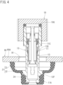
Fig. 4 is a cross-sectional side view of the dividing wall mounting device in a state where a seal protrusion passes through the through-hole. -
Fig. 5 is a cross-sectional side view of the dividing wall mounting device in a state where a flexible flange is press-fitted into a through-hole. -
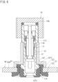
Fig. 6 is a cross-sectional side view of the dividing wall mounting device in a state where a stopper is attached. -
Fig. 7 is a cross-sectional side view of a dividing wall mounting device according to a second embodiment. -
Fig. 8 is a cross-sectional side view of the dividing wall mounting device in a state where a flexible flange is press-fitted into a through-hole. - Hereinafter, a dividing
wall mounting device 10A according to a first embodiment of the present disclosure will be described with reference toFigs. 1 to 6 . The dividingwall mounting device 10A of the present embodiment illustrated inFig. 1 is a tire valve, and includes avalve core 13 inside amain device body 11 extending in the vertical direction inFig. 1 . - In the following description, the vertical direction in
Fig. 1 , which is also an axial direction of themain device body 11, will be simply referred to as the vertical direction, "lower side", "lower end side", and the like inFig. 1 of each portion of the dividingwall mounting device 10A will be simply referred to as "lower side", "lower end side", and the like, and the opposite side will be simply referred to as "upper side", "upper end side", and the like. Note that the lower end side of themain device body 11 corresponds to "one end side in an axial direction" described in the claims, and the upper end side of themain device body 11 corresponds to "other end side in the axial direction" described in the claims. - The above-described
valve core 13 has a structure in which ashaft 15 extending in the vertical direction is supported by a core sleeve 14. The core sleeve 14 is formed by rotatably coupling ashort sleeve 14B to an upper end portion of along sleeve 14A. In theshort sleeve 14B, a bridge 14D is formed so as to straddle an upper surface opening of an inner space, and a position near an upper end of theshaft 15 passes through a through-hole formed in the bridge 14D. Acompression coil spring 17 is attached between anupper end protrusion 15A formed by caulking the upper end of theshaft 15 and the bridge 14D. Avalve body 16 protrudes from a position near a lower end of theshaft 15, and thevalve body 16 is pressed against avalve port 14K at a lower end of the core sleeve 14 by the resilient force of thecompression coil spring 17. Furthermore, athread portion 14N is formed on a side surface of theshort sleeve 14B. - The
main device body 11 includes ametal support sleeve 12 that houses thevalve core 13. Thesupport sleeve 12 has a cylindrical shape as a whole, and thevalve core 13 is inserted into thesupport sleeve 12, and thethread portion 14N of the core sleeve 14 is fastened by athread portion 12N formed at a position near an upper end of an inner surface of thesupport sleeve 12. In addition, atapered portion 12T whose inner diameter decreases downward is provided at an intermediate position in thesupport sleeve 12, and aseal ring 14S attached to an outer surface of thelong sleeve 14A is pressed thereto. Normally, passage of a fluid through thesupport sleeve 12 is restricted by thevalve core 13. When theshaft 15 is pushed downward against the resilient force of thecompression coil spring 17, thevalve port 14K is opened, and the fluid passes through thesupport sleeve 12. - An upper end portion on the outer surface side of the
support sleeve 12 is enlarged in diameter in a stepped manner to form an upper end sidelarge diameter portion 11C (corresponding to "other end side large diameter portion" in the claims). In addition, athread portion 11N is formed on an outer side surface of the upper end sidelarge diameter portion 11C, and athread portion 19N of alid body 19 is screwed onto thethread portion 11N, so that an upper end opening of thesupport sleeve 12 is closed by thelid body 19. On an inner upper surface of thelid body 19, apacking 19G is disposed in an overlapping manner, and an upper end of the upper end sidelarge diameter portion 11C abuts on thepacking 19G. - A lower end portion of the
support sleeve 12 is covered with an elastic coveringmember 24, and a buriedflange 12F is formed in a portion of thesupport sleeve 12 covered with the elastic coveringmember 24. The buriedflange 12F has an upper surface 12F1 protruding laterally from a position near a lower end of the outer surface of thesupport sleeve 12 and perpendicular to an axial direction of thesupport sleeve 12, a side surface 12F2 having a uniform outer diameter, and a tapered surface 12F3 reducing in diameter downward. - The elastic covering
member 24 is made of, for example, vulcanized rubber together with aseal protrusion 21 described later, and is fixed to thesupport sleeve 12 by being molded around the lower end portion of thesupport sleeve 12. Theelastic covering member 24 has a uniform outer diameter, extends in the vertical direction, and has a lower end outer edge portion chamfered. In addition, an upper surface of theelastic covering member 24 is disposed to be flush with the upper surface 12F1 of the buriedflange 12F, while a lower surface is positioned below a lower end surface of thesupport sleeve 12 and covers a lower surface of thesupport sleeve 12. Furthermore, an opening corresponding to a lower end opening of thesupport sleeve 12 is formed at the center of the lower surface of the elastic coveringmember 24. - The
entire seal protrusion 21 has, for example, a bowl shape, and includes aflexible flange 22 protruding laterally from an upper end portion of an outer surface of the elastic coveringmember 24 and acylindrical portion 23 standing upward from a distal end portion of theflexible flange 22, and a portion between theflexible flange 22 and thecylindrical portion 23 is curved. A thickness of theseal protrusion 21 is uniform from a proximal end of theflexible flange 22 to a position before the curved portion between theflexible flange 22 and thecylindrical portion 23, and gradually increases from the start position of the curved portion to the distal end of thecylindrical portion 23. An upper surface of theflexible flange 22 and the upper surface 12F1 of the buriedflange 12F are flush with each other. - The entire dividing
wall mounting device 10A except for theseal protrusion 21 is themain device body 11 described above. A portion of themain device body 11 whose outer surface is covered with the elastic coveringmember 24 forms a lower end sidelarge diameter portion 11A (corresponding to "one end side large diameter portion" in the claims), and a portion between the lower end sidelarge diameter portion 11A and the above-described upper end sidelarge diameter portion 11C is asmall diameter portion 11B having an outer diameter smaller than those of the lower end sidelarge diameter portion 11A and the upper end sidelarge diameter portion 11C. Thus, the dividingwall mounting device 10A of the present embodiment has a shape in which theseal protrusion 21 protrudes laterally from the vicinity of a stepped portion between the lower end sidelarge diameter portion 11A and thesmall diameter portion 11B of themain device body 11. - As illustrated in
Fig. 6 , the dividingwall mounting device 10A includes astopper 50 that can be attached to thesmall diameter portion 11B of themain device body 11. As illustrated inFig. 2 , thestopper 50 has a structure in which one place in a circumferential direction of a cylindrical body whose lower end portion is enlarged in diameter in a stepped manner is entirely cut out with a constant width in the vertical direction. In addition, the enlarged lower end portion of thestopper 50 forms acap portion 52 in the claims, and an inner diameter thereof is slightly larger than an inner diameter of the through-hole 91 to which the dividingwall mounting device 10A is attached. Furthermore, an inner diameter of a small-diametercylindrical portion 51 of thestopper 50 on the upper side of thecap portion 52 is larger than the outer diameter of thesmall diameter portion 11B and smaller than the outer diameter of the upper end sidelarge diameter portion 11C of themain device body 11. Furthermore, the entire height of thestopper 50 is slightly longer than the entire length of thesmall diameter portion 11B of themain device body 11. A method of using thestopper 50 will be described later. - The configuration of the dividing
wall mounting device 10A of the present embodiment has been described above. Next, functions and effects of the dividingwall mounting device 10A will be described. - The dividing
wall mounting device 10A is attached to the through-hole 91 of arim 90A of awheel 90. Note that thewheel 90 and a tire form a container that stores a fluid (specifically, compressed air), and therim 90A of thewheel 90 forms a "dividing wall" in the claims that separates an inner region in the tire from the outside. - When the dividing
wall mounting device 10A is attached to thewheel 90, as illustrated inFig. 1 , the dividingwall mounting device 10A is disposed outside the tire in a state where thestopper 50 is removed, and is inserted into the through-hole 91 of therim 90A from the lower end sidelarge diameter portion 11A side. Then, as illustrated inFig. 3 , the flexible flange is brought into a first state where theflexible flange 22 collapses towards thesmall diameter portion 11B side of themain device body 11 and narrows due to contact with an opening edge of the through-hole 91, thecylindrical portion 23 is brought into a state where thecylindrical portion 23 extends upward from an upper end portion of theflexible flange 22 and narrows, and they pass through the through-hole 91. - As illustrated in
Fig. 4 , theflexible flange 22 and thecylindrical portion 23 are restored to the original state inside the tire after passing through the through-hole 91. From there, the dividingwall mounting device 10A is pulled back in the direction opposite to the insertion direction. Then, as illustrated inFig. 5 , theflexible flange 22 is brought into a second state where theflexible flange 22 collapses towards the lower end sidelarge diameter portion 11A side of themain device body 11 and narrows due to contact with the opening edge of the through-hole 91, and thecylindrical portion 23 is brought into a state where thecylindrical portion 23 protrudes laterally from a lower end of theflexible flange 22. - Here, since the lower end side
large diameter portion 11A of themain device body 11 positioned inside theflexible flange 22 in the second state is larger than thesmall diameter portion 11B of themain device body 11 positioned inside theflexible flange 22 in the first state, the outer diameter of theflexible flange 22 is larger in the second state than in the first state. Then, theflexible flange 22 in the second state is press-fitted into the through-hole 91. - Specifically, first, portions of the
flexible flange 22 and theelastic covering member 24 overlapping the outside of the side surface 12F2 of the buriedflange 12F enter the through-hole 91. Since the portions have the smallest compressive deformation allowance obtained by combining theflexible flange 22 and theelastic covering member 24, the portions are press-fitted with a high press-fitting resistance. Then, as illustrated inFig. 5 , when most of the side surface 12F2 of the buriedflange 12F passes through the through-hole 91 and the press-fitting resistance slightly decreases, thecylindrical portion 23 comes into contact with the opening edge of the through-hole 91, and is not press-fitted into the through-hole 91 any further. - As a result, the dividing
wall mounting device 10A is fixed to the through-hole 91 in a state of being difficult to move from the through-hole 91 to the outside or the inside of therim 90A. In order to strengthen the fixation, thestopper 50 is attached to the dividingwall mounting device 10A from the side. For the attachment, an opening edge of a side surface opening 50K (seeFig. 2 ) of thestopper 50 is pressed against thesmall diameter portion 11B of the dividingwall mounting device 10A from the side. Then, thestopper 50 is elastically deformed such that theside surface opening 50K opens laterally, and thestopper 50 elastically returns when thesmall diameter portion 11B is taken inside thestopper 50. Then, an upper surface of thestopper 50 is adjacent to or in contact with a step surface between the upper end sidelarge diameter portion 11C and thesmall diameter portion 11B of themain device body 11, and a lower surface of thestopper 50 is adjacent to or in contact with the opening edge of the through-hole 91 on an outer surface of therim 90A, thereby preventing the dividingwall mounting device 10A from being pushed into therim 90A from the through-hole 91. - As described above, the dividing
wall mounting device 10A of the present embodiment can be attached to the through-hole 91 from the outside of therim 90A, and is more convenient than a conventional one. In addition, since theflexible flange 22 press-fitted into the through-hole 91 protrudes laterally from the vicinity of the stepped portion between the lower end sidelarge diameter portion 11A and thesmall diameter portion 11B of themain device body 11, it is possible to increase the difference between the outer diameter of theflexible flange 22 in the first state where theflexible flange 22 collapses towards thesmall diameter portion 11B side and the outer diameter of theflexible flange 22 in the second state where theflexible flange 22 collapses towards the lower end sidelarge diameter portion 11A side, so that theflexible flange 22 can easily pass through the through-hole 91 when theflexible flange 22 is set in the first state, and the press-fitting strength into the through-hole 91 can be increased when theflexible flange 22 is set in the second state. - In addition, since the
flexible flange 22 made of an elastomer and theelastic covering member 24 made of an elastomer forming the lower end sidelarge diameter portion 11A are overlapped and press-fitted into the through-hole 91, both theflexible flange 22 and theelastic covering member 24 can be compressed and deformed at the time of press-fitting, and the press-fitting deformation allowance can be easily secured. - Furthermore, since the buried
flange 12F of thesupport sleeve 12 is buried in theelastic covering member 24, the strength and resistance of the press-fitting can be easily changed to a desired level by changing the size and shape of the buriedflange 12F. In addition, the dividingwall mounting device 10A is fixed to therim 90A even in a state where thestopper 50 is not attached, but the fixing is strengthened by attaching thestopper 50. Moreover, since thestopper 50 can be attached to and detached from themain device body 11 from the side, attachment and detachment work can be easily performed. In addition, since a portion of theflexible flange 22 press-fitted into the through-hole 91 and protruding from therim 90A is covered and protected by thecap portion 52 of thestopper 50, reliability is also high. - In order to remove the dividing
wall mounting device 10A attached to therim 90A, it suffices that thestopper 50 is detached from the dividingwall mounting device 10A, and theflexible flange 22 and theelastic covering member 24 protruding outward from the through-hole 91 are cut with, for example, a nipper or the like to pull out the dividingwall mounting device 10A from the through-hole 91. In addition, in the above description, the dividingwall mounting device 10A is attached from the outside of therim 90A. However, if thestopper 50 is not used, the dividingwall mounting device 10A can be attached from the inside of therim 90A, and may be used in such a manner as necessary. - A dividing
wall mounting device 10B of the present embodiment is illustrated inFigs. 7 and8 . The dividingwall mounting device 10B has aboard housing chamber 11D at a lower end portion of amain device body 11V, and accommodates acircuit board 42 therein. Specifically, theboard housing chamber 11D is formed by enlarging the diameter of a portion of asupport sleeve 12V extended downward from theelastic covering member 24, and a lower surface thereof is closed by alid plate 11E. Note that avent 11F is formed in theboard housing chamber 11D. - A
power supply circuit 43, acontrol circuit 44, awireless circuit 45, apressure sensor 46, anacceleration sensor 47, and the like are mounted on thecircuit board 42. Then, thecontrol circuit 44, thewireless circuit 45, and the like receive power through thepower supply circuit 43 from asecondary battery 48 housed in theboard housing chamber 11D together with thecircuit board 42, and wirelessly transmit detection results of thepressure sensor 46 and theacceleration sensor 47. - In addition, a pair of
bus bars 40 for charging thesecondary battery 48 is connected to thepower supply circuit 43. The pair of bus bars 40 extends from theboard housing chamber 11D to an upper end portion of thesupport sleeve 12V. Furthermore, the pair of bus bars 40 penetrates aseal member 41 filled in an area excluding the upper end portion and theboard housing chamber 11D in thesupport sleeve 12V, and upper end portions of the bus bars 40 protrude from an upper surface of theseal member 41 as a pair of chargingelectrodes 40K. - A
flexible flange 22X of the present embodiment has a disk shape without thecylindrical portion 23 of the first embodiment, and the thickness thereof gradually increases towards the distal end. Furthermore, for example, anannular ridge 22Y having a triangular cross section protrudes from a proximal end portion of an upper surface of theflexible flange 22X. The lower surface of theelastic covering member 24 overlaps an upper surface of theboard housing chamber 11D, and the buriedflange 12F of the first embodiment is not buried in theelastic covering member 24. - The configuration of the dividing
wall mounting device 10B of the present embodiment has been described above. Similarly to the dividingwall mounting device 10A of the first embodiment, the dividingwall mounting device 10B is inserted from the outside into the through-hole 91 of therim 90A of thewheel 90 and then pulled back, so that theflexible flange 22X is press-fitted into the through-hole 91 in a state of overlapping the outside of theelastic covering member 24 as illustrated inFig. 8 . Then, theannular ridge 22Y is locked to the opening edge of the through-hole 91 on the outer surface of therim 90A, whereby the dividingwall mounting device 10B is prevented from being pushed back to the inner side of therim 90A. Furthermore, after the dividingwall mounting device 10B is attached to thewheel 90, the above-described detection results are wirelessly transmitted, whereby the pressure in the tire and the behavior of the wheel can be monitored. -
- (1) The
stopper 50 of the first embodiment has a structure to be attached to themain device body 11 from the side, but for example, the upper end sidelarge diameter portion 11C of themain device body 11 may have the same outer diameter as thesmall diameter portion 11B, thethread portion 11N may be formed up to a lower end portion of thesmall diameter portion 11B, and a stopper having a nut structure instead of thestopper 50 may be screwed and attached thereto. - (2) Instead of the buried
flange 12F, a plurality of protrusions may be dispersedly arranged in a circumferential surface direction of a lower end portion of themain device body 11. - (3) Portions that are not press-fitted into the through-
hole 91, such as thecylindrical portion 23 and theannular ridge 22Y, may be provided so as to be scattered in a circumferential direction without being continuous in the circumferential direction. - (4) Although the
flexible flange 22 is integrally formed with theelastic covering member 24 fixed to themain device body 11 at the time of molding the vulcanized rubber, theflexible flange 22 or theelastic covering member 24 may be fixed to themain device body 11 with an adhesive, or theflexible flange 22 or theelastic covering member 24 may be fixed to themain device body 11 with a structure other than these. - (5) The
support sleeve 12 is made of metal, but may be made of resin. Theflexible flange 22, theelastic covering member 24, and the like are made of vulcanized rubber, but need not be made of vulcanized rubber as long as they are made of an elastomer. - (6) In the above embodiments, the examples of the dividing
wall mounting devices wheel 90 have been described, but the structures of the present disclosure may be applied to a dividing wall mounting device attached to a pipe through which a fluid flows, a tank that stores a fluid, and the like. - Although specific examples of the technology included in the claims are disclosed in the present specification and drawings, the technology described in the claims is not limited to these specific examples, and includes those obtained by variously modifying and changing the specific examples, and also includes those obtained by singly extracting a part from the specific examples.
-
- 10A, 10B dividing wall mounting device
- 11, 11V main device body
- 11A lower end side large diameter portion (one end side large diameter portion)
- 11B small diameter portion
- 11C upper end side large diameter portion (other end side large diameter portion)
- 12, 12V support sleeve
- 12F buried flange
- 22, 22X flexible flange
- 22X flexible flange
- 23 cylindrical portion
- 24 elastic covering member
- 50 stopper
- 52 cap portion
- 90A rim (dividing wall)
- 91 through-hole
Claims (7)
- A dividing wall mounting device configured to be attached to a through-hole of a dividing wall that separates, from an outside, an inner region in which a fluid is stored or flows, the dividing wall mounting device comprising:a main device body extending along a central axis of the through-hole; anda flexible flange made of an elastomer and protruding laterally from an intermediate position in an axial direction of the main device body, and when the dividing wall mounting device is inserted into the through-hole from one end side in the axial direction, the flexible flange passing through the through-hole in a first state where the flexible flange collapses towards an other end side in the axial direction and narrows due to contact with an opening edge of the through-hole, and when the dividing wall mounting device is pulled back in a direction opposite to the insertion, the flexible flange being press-fitted into the through-hole in a second state where the flexible flange collapses towards the one end side in the axial direction and narrows due to contact with the opening edge of the through-hole, and has an outer diameter larger than an outer diameter in the first state.
- The dividing wall mounting device according to claim 1, whereinthe main device body includes a one end side large diameter portion obtained by enlarging an outer diameter on the one end side of an intermediate position in the axial direction of the main device body, and a small diameter portion provided on the other end side of the one end side large diameter portion and having an outer diameter smaller than an outer diameter of the one end side large diameter portion, andthe flexible flange protrudes laterally from a stepped portion between the one end side large diameter portion and the small diameter portion or a vicinity of the stepped portion.
- The dividing wall mounting device according to claim 1 or 2, further comprising a stopper configured to be locked or engaged on the other end side of the flexible flange of the main device body in a state where the flexible flange is press-fitted into the through-hole, and configured to restrict movement of the dividing wall mounting device in a direction of the insertion.
- The dividing wall mounting device according to claim 3, whereinthe main device body includes an other end side large diameter portion obtained by enlarging an outer diameter on the other end side of the small diameter portion to be larger than the outer diameter of the small diameter portion, andthe stopper is formed by forming a vertical split slit in a cylindrical body, and is attached from a side between the other end side large diameter portion and the dividing wall in the state where the flexible flange is press-fitted into the through-hole.
- The dividing wall mounting device according to claim 3 or 4, wherein the stopper includes a cap portion that covers a portion of the flexible flange press-fitted into the through-hole, the portion protruding from the dividing wall.
- The dividing wall mounting device according to any one of claims 1 to 6, wherein
the main device body includes:a support sleeve made of metal or resin;an elastic covering member made of an elastomer that covers the one end side of the support sleeve and forms the one end side large diameter portion side; anda buried flange integrally formed with the support sleeve and buried in the elastic covering member, andthe flexible flange is integrally formed with the elastic covering member. - The dividing wall mounting device according to any one of claims 1 to 6, further comprising a cylindrical portion that protrudes from a distal end of the flexible flange to the other end side in the axial direction.
Applications Claiming Priority (2)
| Application Number | Priority Date | Filing Date | Title |
|---|---|---|---|
| JP2020135521A JP7280226B2 (en) | 2020-08-11 | 2020-08-11 | Bulkhead mounted equipment |
| PCT/JP2021/008648 WO2022034708A1 (en) | 2020-08-11 | 2021-03-05 | Dividing wall mounting device |
Publications (2)
| Publication Number | Publication Date |
|---|---|
| EP4144545A1 true EP4144545A1 (en) | 2023-03-08 |
| EP4144545A4 EP4144545A4 (en) | 2023-11-22 |
Family
ID=80247118
Family Applications (1)
| Application Number | Title | Priority Date | Filing Date |
|---|---|---|---|
| EP21855787.4A Withdrawn EP4144545A4 (en) | 2020-08-11 | 2021-03-05 | MOUNTING DEVICE FOR PARTITION WALL |
Country Status (5)
| Country | Link |
|---|---|
| US (1) | US20230278377A1 (en) |
| EP (1) | EP4144545A4 (en) |
| JP (1) | JP7280226B2 (en) |
| CN (1) | CN115697731A (en) |
| WO (1) | WO2022034708A1 (en) |
Families Citing this family (2)
| Publication number | Priority date | Publication date | Assignee | Title |
|---|---|---|---|---|
| JP2024061439A (en) * | 2022-10-21 | 2024-05-07 | 太平洋工業株式会社 | Valve stem and its mounting structure, and method for manufacturing tire wheel with valve stem |
| EP4725719A1 (en) * | 2024-01-31 | 2026-04-15 | Pacific Industrial Co., Ltd. | Tire valve and cover sleeve |
Family Cites Families (16)
| Publication number | Priority date | Publication date | Assignee | Title |
|---|---|---|---|---|
| GB770033A (en) * | 1953-03-26 | 1957-03-13 | Goodrich Co B F | Improvements in inflating valve |
| GB758318A (en) | 1953-12-24 | 1956-10-03 | Us Rubber Co | Improvements in valve assemblies |
| FR1117877A (en) | 1954-08-20 | 1956-05-29 | Goodyear Tire & Rubber | Rim valve intended to receive a tubeless tire |
| GB794701A (en) * | 1955-11-21 | 1958-05-07 | Us Rubber Co | Improvements in valves for inflatable articles |
| US2813568A (en) * | 1956-02-21 | 1957-11-19 | Scovill Manufacturing Co | Tubeless tire valve |
| DE1173353B (en) * | 1958-07-09 | 1964-07-02 | Daimler Benz Ag | Control valve for a curve inclination compensation device in motor vehicles |
| JP4046409B2 (en) * | 1998-04-21 | 2008-02-13 | カルソニックカンセイ株式会社 | Pressure control valve seal structure |
| US7694557B2 (en) * | 2007-01-24 | 2010-04-13 | Continental Automotive Systems Us, Inc. | Tire pressure monitoring sensor and mounting method |
| CN101303089B (en) * | 2008-07-02 | 2011-06-01 | 胜利油田胜利阀业有限责任公司 | Globe valve |
| JP5504132B2 (en) | 2010-10-25 | 2014-05-28 | 太平洋工業株式会社 | Snap-in valve and tire valve unit |
| JP2014118104A (en) * | 2012-12-19 | 2014-06-30 | Aoyama Seisakusho Co Ltd | Grommet |
| JP2014073843A (en) | 2014-01-27 | 2014-04-24 | Pacific Ind Co Ltd | Snap-in valve and tire valve unit |
| JP6333205B2 (en) * | 2015-03-23 | 2018-05-30 | 太平洋工業株式会社 | Tire valve |
| DE102015210461A1 (en) * | 2015-06-08 | 2016-12-08 | Alligator Ventilfabrik Gmbh | Tire valve for a pneumatic tire of a vehicle |
| DE102017129950A1 (en) * | 2017-02-08 | 2018-08-09 | Huf Hülsbeck & Fürst Gmbh & Co. Kg | Tire valve for a pneumatic tire of a vehicle |
| DE102017002069B4 (en) * | 2017-03-03 | 2024-12-05 | TOX-Dübel-Technik GmbH | fastening system with a screw-in anchor |
-
2020
- 2020-08-11 JP JP2020135521A patent/JP7280226B2/en active Active
-
2021
- 2021-03-05 CN CN202180039969.8A patent/CN115697731A/en active Pending
- 2021-03-05 WO PCT/JP2021/008648 patent/WO2022034708A1/en not_active Ceased
- 2021-03-05 EP EP21855787.4A patent/EP4144545A4/en not_active Withdrawn
- 2021-03-05 US US18/008,229 patent/US20230278377A1/en not_active Abandoned
Also Published As
| Publication number | Publication date |
|---|---|
| JP7280226B2 (en) | 2023-05-23 |
| WO2022034708A1 (en) | 2022-02-17 |
| EP4144545A4 (en) | 2023-11-22 |
| US20230278377A1 (en) | 2023-09-07 |
| CN115697731A (en) | 2023-02-03 |
| JP2022032065A (en) | 2022-02-25 |
Similar Documents
| Publication | Publication Date | Title |
|---|---|---|
| JP4996593B2 (en) | Gas relief valve | |
| JP4522953B2 (en) | Tire valve unit | |
| CN102361286B (en) | Sealing structure for wire lead-out hole and method for sealing wire lead-out hole | |
| CN112352342B (en) | Secondary battery and method for manufacturing same | |
| JP2008234904A (en) | Grommet and assembly method | |
| EP1911610A1 (en) | Tire valve unit | |
| US20120291220A1 (en) | Grommet for wire harness | |
| US20230278377A1 (en) | Dividing wall mounting device | |
| EP2982953B1 (en) | Pressure detection device and method for assembling pressure detection device | |
| US10670484B2 (en) | Pressure sensor unit including snap fit circular seal | |
| JP5504132B2 (en) | Snap-in valve and tire valve unit | |
| KR102160468B1 (en) | Connecting cap and cdc system-main harness connecting apparatus | |
| US20180275006A1 (en) | Oil pressure sensor attachment structure | |
| JP2014073843A (en) | Snap-in valve and tire valve unit | |
| US9784228B2 (en) | Fuel supply apparatus | |
| CN212643402U (en) | Power assembly hydraulic suspension and car | |
| US20230387673A1 (en) | Cable gland | |
| US20190039654A1 (en) | Hydraulic Body Mount | |
| CN101545517A (en) | Dust-proof cover | |
| EP4023466A1 (en) | Tire valve and method for manufacturing tire valve | |
| EP4119364A1 (en) | Valve stem and tire valve | |
| CN108995487B (en) | Tire pressure sensor assembly and wheel comprising same | |
| US20020117790A1 (en) | Engine mount | |
| CN222950304U (en) | Sealing element for air spring and air spring | |
| EP4725720A1 (en) | Tire valve and tilt restriction member |
Legal Events
| Date | Code | Title | Description |
|---|---|---|---|
| STAA | Information on the status of an ep patent application or granted ep patent |
Free format text: STATUS: THE INTERNATIONAL PUBLICATION HAS BEEN MADE |
|
| PUAI | Public reference made under article 153(3) epc to a published international application that has entered the european phase |
Free format text: ORIGINAL CODE: 0009012 |
|
| STAA | Information on the status of an ep patent application or granted ep patent |
Free format text: STATUS: REQUEST FOR EXAMINATION WAS MADE |
|
| 17P | Request for examination filed |
Effective date: 20221202 |
|
| AK | Designated contracting states |
Kind code of ref document: A1 Designated state(s): AL AT BE BG CH CY CZ DE DK EE ES FI FR GB GR HR HU IE IS IT LI LT LU LV MC MK MT NL NO PL PT RO RS SE SI SK SM TR |
|
| DAV | Request for validation of the european patent (deleted) | ||
| DAX | Request for extension of the european patent (deleted) | ||
| A4 | Supplementary search report drawn up and despatched |
Effective date: 20231023 |
|
| RIC1 | Information provided on ipc code assigned before grant |
Ipc: B60C 29/02 20060101AFI20231017BHEP |
|
| GRAP | Despatch of communication of intention to grant a patent |
Free format text: ORIGINAL CODE: EPIDOSNIGR1 |
|
| STAA | Information on the status of an ep patent application or granted ep patent |
Free format text: STATUS: GRANT OF PATENT IS INTENDED |
|
| INTG | Intention to grant announced |
Effective date: 20240322 |
|
| STAA | Information on the status of an ep patent application or granted ep patent |
Free format text: STATUS: THE APPLICATION IS DEEMED TO BE WITHDRAWN |
|
| 18D | Application deemed to be withdrawn |
Effective date: 20240723 |