EP4144536B1 - Radlagervorrichtung - Google Patents
Radlagervorrichtung Download PDFInfo
- Publication number
- EP4144536B1 EP4144536B1 EP21795477.5A EP21795477A EP4144536B1 EP 4144536 B1 EP4144536 B1 EP 4144536B1 EP 21795477 A EP21795477 A EP 21795477A EP 4144536 B1 EP4144536 B1 EP 4144536B1
- Authority
- EP
- European Patent Office
- Prior art keywords
- flange part
- side end
- large diameter
- end surface
- guide surface
- Prior art date
- Legal status (The legal status is an assumption and is not a legal conclusion. Google has not performed a legal analysis and makes no representation as to the accuracy of the status listed.)
- Active
Links
Images


Classifications
-
- F—MECHANICAL ENGINEERING; LIGHTING; HEATING; WEAPONS; BLASTING
- F16—ENGINEERING ELEMENTS AND UNITS; GENERAL MEASURES FOR PRODUCING AND MAINTAINING EFFECTIVE FUNCTIONING OF MACHINES OR INSTALLATIONS; THERMAL INSULATION IN GENERAL
- F16C—SHAFTS; FLEXIBLE SHAFTS; ELEMENTS OR CRANKSHAFT MECHANISMS; ROTARY BODIES OTHER THAN GEARING ELEMENTS; BEARINGS
- F16C33/00—Parts of bearings; Special methods for making bearings or parts thereof
- F16C33/30—Parts of ball or roller bearings
- F16C33/58—Raceways; Race rings
- F16C33/583—Details of specific parts of races
-
- F—MECHANICAL ENGINEERING; LIGHTING; HEATING; WEAPONS; BLASTING
- F16—ENGINEERING ELEMENTS AND UNITS; GENERAL MEASURES FOR PRODUCING AND MAINTAINING EFFECTIVE FUNCTIONING OF MACHINES OR INSTALLATIONS; THERMAL INSULATION IN GENERAL
- F16C—SHAFTS; FLEXIBLE SHAFTS; ELEMENTS OR CRANKSHAFT MECHANISMS; ROTARY BODIES OTHER THAN GEARING ELEMENTS; BEARINGS
- F16C19/00—Bearings with rolling contact, for exclusively rotary movement
- F16C19/22—Bearings with rolling contact, for exclusively rotary movement with bearing rollers essentially of the same size in one or more circular rows, e.g. needle bearings
- F16C19/34—Bearings with rolling contact, for exclusively rotary movement with bearing rollers essentially of the same size in one or more circular rows, e.g. needle bearings for both radial and axial load
- F16C19/38—Bearings with rolling contact, for exclusively rotary movement with bearing rollers essentially of the same size in one or more circular rows, e.g. needle bearings for both radial and axial load with two or more rows of rollers
- F16C19/383—Bearings with rolling contact, for exclusively rotary movement with bearing rollers essentially of the same size in one or more circular rows, e.g. needle bearings for both radial and axial load with two or more rows of rollers with tapered rollers, i.e. rollers having essentially the shape of a truncated cone
- F16C19/385—Bearings with rolling contact, for exclusively rotary movement with bearing rollers essentially of the same size in one or more circular rows, e.g. needle bearings for both radial and axial load with two or more rows of rollers with tapered rollers, i.e. rollers having essentially the shape of a truncated cone with two rows, i.e. double-row tapered roller bearings
- F16C19/386—Bearings with rolling contact, for exclusively rotary movement with bearing rollers essentially of the same size in one or more circular rows, e.g. needle bearings for both radial and axial load with two or more rows of rollers with tapered rollers, i.e. rollers having essentially the shape of a truncated cone with two rows, i.e. double-row tapered roller bearings in O-arrangement
-
- F—MECHANICAL ENGINEERING; LIGHTING; HEATING; WEAPONS; BLASTING
- F16—ENGINEERING ELEMENTS AND UNITS; GENERAL MEASURES FOR PRODUCING AND MAINTAINING EFFECTIVE FUNCTIONING OF MACHINES OR INSTALLATIONS; THERMAL INSULATION IN GENERAL
- F16C—SHAFTS; FLEXIBLE SHAFTS; ELEMENTS OR CRANKSHAFT MECHANISMS; ROTARY BODIES OTHER THAN GEARING ELEMENTS; BEARINGS
- F16C33/00—Parts of bearings; Special methods for making bearings or parts thereof
- F16C33/30—Parts of ball or roller bearings
- F16C33/34—Rollers; Needles
- F16C33/36—Rollers; Needles with bearing-surfaces other than cylindrical, e.g. tapered; with grooves in the bearing surfaces
- F16C33/366—Tapered rollers, i.e. rollers generally shaped as truncated cones
-
- F—MECHANICAL ENGINEERING; LIGHTING; HEATING; WEAPONS; BLASTING
- F16—ENGINEERING ELEMENTS AND UNITS; GENERAL MEASURES FOR PRODUCING AND MAINTAINING EFFECTIVE FUNCTIONING OF MACHINES OR INSTALLATIONS; THERMAL INSULATION IN GENERAL
- F16C—SHAFTS; FLEXIBLE SHAFTS; ELEMENTS OR CRANKSHAFT MECHANISMS; ROTARY BODIES OTHER THAN GEARING ELEMENTS; BEARINGS
- F16C33/00—Parts of bearings; Special methods for making bearings or parts thereof
- F16C33/30—Parts of ball or roller bearings
- F16C33/58—Raceways; Race rings
- F16C33/583—Details of specific parts of races
- F16C33/585—Details of specific parts of races of raceways, e.g. ribs to guide the rollers
-
- B—PERFORMING OPERATIONS; TRANSPORTING
- B60—VEHICLES IN GENERAL
- B60B—VEHICLE WHEELS; CASTORS; AXLES FOR WHEELS OR CASTORS; INCREASING WHEEL ADHESION
- B60B35/00—Axle units; Parts thereof ; Arrangements for lubrication of axles
- B60B35/12—Torque-transmitting axles
- B60B35/18—Arrangement of bearings
-
- F—MECHANICAL ENGINEERING; LIGHTING; HEATING; WEAPONS; BLASTING
- F16—ENGINEERING ELEMENTS AND UNITS; GENERAL MEASURES FOR PRODUCING AND MAINTAINING EFFECTIVE FUNCTIONING OF MACHINES OR INSTALLATIONS; THERMAL INSULATION IN GENERAL
- F16C—SHAFTS; FLEXIBLE SHAFTS; ELEMENTS OR CRANKSHAFT MECHANISMS; ROTARY BODIES OTHER THAN GEARING ELEMENTS; BEARINGS
- F16C2240/00—Specified values or numerical ranges of parameters; Relations between them
- F16C2240/40—Linear dimensions, e.g. length, radius, thickness, gap
- F16C2240/46—Gap sizes or clearances
-
- F—MECHANICAL ENGINEERING; LIGHTING; HEATING; WEAPONS; BLASTING
- F16—ENGINEERING ELEMENTS AND UNITS; GENERAL MEASURES FOR PRODUCING AND MAINTAINING EFFECTIVE FUNCTIONING OF MACHINES OR INSTALLATIONS; THERMAL INSULATION IN GENERAL
- F16C—SHAFTS; FLEXIBLE SHAFTS; ELEMENTS OR CRANKSHAFT MECHANISMS; ROTARY BODIES OTHER THAN GEARING ELEMENTS; BEARINGS
- F16C2240/00—Specified values or numerical ranges of parameters; Relations between them
- F16C2240/40—Linear dimensions, e.g. length, radius, thickness, gap
- F16C2240/70—Diameters; Radii
-
- F—MECHANICAL ENGINEERING; LIGHTING; HEATING; WEAPONS; BLASTING
- F16—ENGINEERING ELEMENTS AND UNITS; GENERAL MEASURES FOR PRODUCING AND MAINTAINING EFFECTIVE FUNCTIONING OF MACHINES OR INSTALLATIONS; THERMAL INSULATION IN GENERAL
- F16C—SHAFTS; FLEXIBLE SHAFTS; ELEMENTS OR CRANKSHAFT MECHANISMS; ROTARY BODIES OTHER THAN GEARING ELEMENTS; BEARINGS
- F16C2326/00—Articles relating to transporting
- F16C2326/01—Parts of vehicles in general
- F16C2326/02—Wheel hubs or castors
Definitions
- the present invention relates to a bearing device for a vehicle wheel.
- a bearing device for a vehicle wheel including a multi-row tapered roller bearing is known.
- a plurality of tapered rollers are rollably accommodated between a multi-row outer rolling surface (outer raceway surface) formed on an inner periphery of an outer member and a plurality of inner rolling surfaces (inner raceway surface) formed on an outer periphery of an inner member, and the inner raceway surface (or the outer raceway surface) has a large flange part integrally formed with the inner raceway surface, the large flange part having a guide surface with which a large end surface (large diameter-side end surface) of each of the tapered rollers formed in a convex shape is in sliding contact.
- a chamfered part continuous with an outside surface (or a bore surface) of the large flange part, and a grinding cutout (large flange part-side cutout part) provided at a base of the large flange part are formed, and a rounded part having an arc shape in a cross-sectional view is formed in at least one of the chamfered part or the large flange part-side cutout part.
- lubricating oil enters a gap formed between the large diameter-side end surface of each of the tapered rollers and the guide surface of the large flange part through the rounded part to form an oil film due to a wedge effect, and the lubricating oil is easily drawn into a contact portion between the large diameter-side end surface and the guide surface to increase lubricating performance and durability.
- Patent Literature 2 A further example of a tapered roller bearing is disclosed in Patent Literature 2.
- an axial load applied to the bearing device for a vehicle wheel including such a multi-row tapered roller bearing is borne mainly between the large diameter-side end surface of each of the tapered rollers and the guide surface of the large flange part, and a contact ellipse with a tangential direction of a circular locus when the tapered roller rolls set as a major axis direction is formed at the contact portion between the large diameter-side end surface and the guide surface on the basis of Hertz elastic contact theory.
- the contact portion between the large diameter-side end surface of each of the tapered rollers and the guide surface of the large flange part is in rolling contact with each other with large slippage due to the structure of the bearing, so that wear easily occurs between the large diameter-side end and the guide surface.
- an allowable value of the amount of wear between the large diameter-side end of each of the tapered rollers and the guide surface of the large flange part is not specifically set in advance, so that there is a possibility that the gap between the large diameter-side end and the guide surface (clearance of the large diameter-side end as viewed from the guide surface) is not sufficiently secured and becomes minimal when a travel distance of the vehicle reaches a long distance of about 1 million km, for example.
- the bearing device for a vehicle wheel it is possible to sufficiently secure the gap between the large diameter-side end surface of each of the tapered rollers and the guide surface of the large flange part to maintain the oil film forming ability due to the wedge effect, to reduce the occurrence of, for example, abnormal heat generation caused by metal contact, and to enhance anti-seizing properties.
- a direction parallel to a rotation axis G (see FIG. 1 ) of a bearing device for a vehicle wheel 1 is defined as an "axial direction”
- a direction orthogonal to the rotation axis G is defined as a “radial direction”
- a direction along an arc centered on the rotation axis G is defined as a “circumferential direction”.
- a side adjacent to the rotation axis G in the radial direction is defined as an “inner diameter side”
- a side opposite from the inner diameter side in the radial direction is defined as an “outer diameter side”.
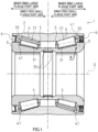
- the bearing device for a vehicle wheel 1 has a structure called the first generation, and primarily includes an outer ring 2 that is an example of an outer member and has, on an inner periphery, outer raceway surfaces 21, 21 of a multi-row type (double-row type in the present embodiment), a pair of inner rings 3, 3 that is an example of an inner member and has, on an outer periphery, inner raceway surfaces 31, 31 of a multi-row type (double-row type in the present embodiment) facing the outer raceway surfaces 21, 21, a plurality of tapered rollers 4, 4, ... rollably accommodated between the outer raceway surfaces 21, 21 and the inner raceway surfaces 31, 31, a pair of cages 5, 5 that hold the plurality of tapered rollers 4, 4 ... so as to make the plurality of tapered rollers 4, 4 ... rollable, seals 6, 6 attached to both ends of the outer ring 2 in the axial direction, and the like.
- the pair of outer raceway surfaces 21, 21 is formed in a mortar shape whose a diameter increases from a center to both ends in the axial direction.
- the inner raceway surface 31 of each inner ring 3 is formed in a conical shape whose diameter increases from a center to an end of the bearing device for a vehicle wheel 1 in the axial direction.
- the pair of inner rings 3, 3 is disposed, on the inner diameter side of the outer ring 2, coaxially with the outer ring 2 with the pair of inner rings 3, 3 facing the outer ring 2, and the bearing device for a vehicle wheel 1 is structured as a multi-row tapered roller bearing of a back-to-back arrangement type.
- a large flange part 32 extending toward the outer diameter side is integrally formed at an end adjacent to a large diameter side of the inner raceway surface 31.
- a small flange part 33 extending toward the outer diameter side and positioned on the inner diameter side relative to the large flange part 32 is integrally formed at an end on the small diameter side of the inner raceway surface 31.
- the "large diameter side” means an enlarged diameter side of the inner raceway surface 31.
- the “small diameter side” means a reduced diameter side of the inner raceway surface 31.
- the plurality of tapered rollers 4, 4, ... held by the cage 5 are disposed on the inner raceway surface 31.
- each tapered roller 4 slidably comes into contact with the large flange part 32 to be guided to move in the radial direction and restricted from moving toward the large diameter side (that is, an inner ring large flange part side) in the axial direction by the large flange part 32.
- each tapered roller 4 comes into contact with the small flange part 33 to be restricted from moving toward the small diameter side (that is, an inner ring small flange part side) in the axial direction by the small flange part 33.
- the outer ring 2, the inner ring 3, and the tapered roller 4 are made of, for example, high-carbon chromium bearing steel such as SUJ2, and are hardened in a range of 58 to 64 HRC up to a core part by through hardening, but are not limited to such a material, and the outer ring 2, the inner ring 3, and the tapered roller 4 may be made of, for example, structural alloy steel such as SCr420, and their surfaces may be hardened in a range of 58 to 64 HRC by carburizing and quenching.
- the cage 5 is formed by, for example, injection molding an engineering plastic such as polyamide (PA) 66, a super engineering plastic such as polyphenylene sulfide (PPS), or a material containing, as a base, thermoplastic synthetic resin of such a plastic, and an appropriate amount of a reinforcing material such as glass fiber (GF).
- PA polyamide
- PPS polyphenylene sulfide
- GF glass fiber
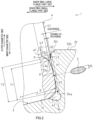
- a large diameter-side end surface 41 of the tapered roller 4 is formed in a convex shape having a predetermined radius of curvature R, and a chamfered part 42 is formed at a corner (peripheral part) on an outer peripheral side of the large diameter-side end surface 41.
- a tapered roller-side cutout part 43 having a circular shape is formed coaxially with the large diameter-side end surface 41 by, for example, header processing.
- the radius of curvature R of the large diameter-side end surface 41 is set so as to make a clearance between the large diameter-side end surface 41 and the guide surface 32a equal to a predetermined value.
- the large flange part 32 of the inner ring 3 has the guide surface 32a having a conical surface shape for guiding the tapered roller 4, and each tapered roller 4 is disposed on the inner raceway surface 31 with the large diameter-side end surface 41 in point contact with the guide surface 32a in a slidable manner.
- a chamfered part 32c and a rounded part 32d are sequentially and continuously formed from an outside surface 32b to the guide surface 32a of the large flange part 32, and in a circumferential cross-sectional view, the chamfered part 32c is formed in a gently curved arc shape having a predetermined radius of curvature r1, and the rounded part 32d is formed in an arc shape having a predetermined radius of curvature r2 sufficiently smaller than the radius of curvature r1 of the chamfered part 32c.
- the large flange part 32 of the inner ring 3 has the chamfered part 32c continuous with the outside surface 32b thereof (of the large flange part 32) and the rounded part 32d that is formed in an arc shape having the predetermined radius of curvature r2 in a cross-sectional view and is continuous with the chamfered part 32c on one side and continuous with the guide surface 32a on the other side.
- the shape of the rounded part 32d is set so as to make the radius of curvature r2 and a degree of rounding equal to their respective predetermined values.
- a start point position of the rounded part 32d is set to a predetermined position.
- a start point of the tapered roller-side cutout part 43 that is, an outer peripheral end 43a is set at a position on the inner diameter side relative to the outside surface 32b of the large flange part 32.
- the outer peripheral end 43a of the tapered roller-side cutout part 43 is positioned in the vicinity of a boundary between the guide surface 32a and the rounded part 32d of the large flange part 32, and an annular space q that is a wedge-shaped gap opened toward the outside surface 32b in the circumferential cross-sectional view is formed between the large diameter-side end surface 41 of the tapered roller 4 and the guide surface 32a of the large flange part 32.
- the start point position of the tapered roller-side cutout part 43 is set to a predetermined position.
- a large flange part-side cutout part 34 continuous with the guide surface 32a is formed at a base of the large flange part 32, that is, a corner between the inner raceway surface 31 and the large flange part 32.
- An edge 34a of the large flange part-side cutout part 34 adjacent to the guide surface 32a is set at a position on the outer diameter side relative to a corner between the large diameter-side end surface 41 and the chamfered part 42 of the tapered roller 4.
- a rounded part formed in an arc shape having a predetermined radius of curvature in a circumferential cross-sectional view, the rounded part circumscribing the guide surface 32a may be separately provided from the edge 34a of the large flange part-side cutout part 34 toward the outer diameter side.
- the bearing device for a vehicle wheel 1 having the above-described structure is excellent in durability against high loads or impact loads, and is suitable mainly for use as a bearing that rotatably supports each wheel of a long-distance transport vehicle with a heavy body weight, such as a truck, a bus, or a pickup truck.
- a conventional bearing device for a vehicle wheel including a multi-row tapered roller bearing when the bearing device is used as a bearing of a long-distance transport vehicle, there is no problem under a condition where a travel distance of the vehicle is about several hundreds of thousands km, but when the travel distance reaches a long distance of, for example, about one million km, the degree of wear between the large diameter-side end surface 41 of the tapered roller 4 and the guide surface 32a of the large flange part 32 of the inner ring 3 increases, and there is a possibility that lubricating oil is not sufficiently drawn into the above-described annular space q that is a wedge-shaped gap.
- a contact ellipse E based on Hertz elastic contact theory appears at the contact portion (contact point P) between the large diameter-side end surface 41 of the tapered roller 4 and the guide surface 32a of the large flange part 32 of the inner ring 3, and it is known that the contact ellipse E increases in size in response to an increase in axial load during the use of the bearing and becomes the maximum, for example, during maximum turning of the vehicle.
- the tapered roller 4 may be inclined and skewed in the circumferential direction relative to a rotation axis g (see FIG. 4A ) thereof due to the influence of an oil film such as lubricating oil, and at this time, the contact ellipse E also changes in position in response to the skew of the tapered roller 4, so that it is not sufficient that only the influence of the contact ellipse E that has become the maximum is taken into account for the setting of the rounded part 32d.
- the bearing device for a vehicle wheel 1 according to the present embodiment allows the bearing device for a vehicle wheel 1 according to the present embodiment to be implemented as a bearing device for a vehicle wheel that reduces the occurrence of, for example, abnormal heat generation caused by metal contact even when the bearing device is used in a long-distance transport vehicle having a heavy body weight and has better anti-seizing properties.
- the bearing device for a vehicle wheel 1 is structured as a multi-row tapered roller bearing of a back-to-back arrangement type, but is not limited to such a bearing, and may be structured as a single-row tapered roller bearing.
- the bearing device for a vehicle wheel 1 has a structure called the first generation as described above, but is not limited to such a structure, and for example, the bearing device for a vehicle wheel 1 may have a structure called the second generation in which an outer ring has a flange or the third generation in which an inner raceway surface is directly formed on an outer periphery of a hub ring.
- the large diameter-side end surface 41 of the tapered roller 4 is formed in a convex shape having the predetermined radius of curvature R as described above, and is in point contact with the guide surface 32a of the large flange part 32 of the inner ring 3 at the contact point P.
- the annular space q that is a wedge-shaped gap opened toward the outside surface 32b in the circumferential cross-sectional view is formed.
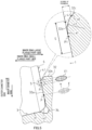
- the large diameter-side end surface 41 of the tapered roller 4 and the guide surface 32a of the large flange part 32 of the inner ring 3 are in sliding contact with each other and are thus prone to wear, as the total rotation count of the bearing device for a vehicle wheel 1 increases, the degree of wear between the large diameter-side end surface 41 and the guide surface 32a gradually increases, and the annular space q gradually decreases and finally disappears accordingly.
- the large diameter-side end surface 41 of the tapered roller 4 and the guide surface 32a of the large flange part 32 of the inner ring 3 are in point contact with each other at a predetermined position (contact point P), and the annular space q located between the large diameter-side end surface 41 and the guide surface 32a has a sufficient gap having a predetermined shape set in advance.
- the gap formed by the annular space q gradually decreases, and when the large diameter-side end surface 41 and/or the guide surface 32a has worn to a moderate degree as illustrated in FIG. 3B , for example, the gap formed by the annular space q becomes the minimum.
- the start point position of the rounded part 32d that is, the position of the inner peripheral end a1 of the rounded part 32d adjacent to the guide surface 32a (see FIG. 2 ) is set with the state where the tapered roller 4 is skewed taken into account in advance in order to reduce the occurrence of galling between the large diameter-side end surface 41 of the tapered roller 4 and the large flange part 32 of the inner ring 3, the skew amount of the tapered roller 4 gradually increases as the degree of wear of the large diameter-side end surface 41 and/or the guide surface 32a increases, and thus galling is highly likely to occur at any point in time.
- the shape of the gap formed by the annular space q that is, the clearance between the large diameter-side end surface 41 and the guide surface 32a (more specifically, a size of a gap between the guide surface 32a and the outer peripheral end 43a of the tapered roller-side cutout part 43) with an amount of wear up to which the oil film forming ability can be kept high enough even when the degree of wear increases at the contact portion (contact point P) between the large diameter-side end surface 41 of the tapered roller 4 and the guide surface 32a of the large flange part 32 of the inner ring 3 taken into account in advance.
- a long-distance transport vehicle such as a truck tends to be longer in travel distance than a passenger vehicle, and may travel a long distance of, for example, about 1 million km, and even when used in such a long-distance transport vehicle, it is important to set the clearance to an optimum value in advance such that the oil film forming ability can be kept high enough.
- the present inventor has found, as a result of intensive studies, that it is possible to keep the oil film forming ability high enough even when the travel distance reaches a long distance of about 1 million km by setting in advance the clearance between the large diameter-side end surface 41 of the tapered roller 4 and the guide surface 32a of the large flange part 32 of the inner ring 3 greater than or equal to 15 ⁇ m.
- the oil film forming ability can be kept high enough by setting in advance the clearance of the large diameter-side end surface 41 as viewed from the contact point P between the large diameter-side end surface 41 of the tapered roller 4 and the guide surface 32a of the large flange part 32 of the inner ring 3 greater than or equal to 15 ⁇ m.
- the amount of wear in the large flange part 32 of the inner ring 3 gradually increased as the travel distance of the long-distance transport vehicle increased up to about 500,000 km. Specifically, the amount of wear increased by 2 ⁇ m until the travel distance increased from 100,000 km to 250,000 km, whereas the amount of wear increased by 5 ⁇ m until the travel distance increased from 250,000 km to 500,000 km.
- the clearance greater than or equal to 15 ⁇ m prevents the gap formed by the annular space q from becoming the minimum as illustrated in FIG. 3B , for example, even when the travel distance of the long-distance transport vehicle provided with the bearing device for a vehicle wheel 1 exceeds 1 million km and allows the gap between the large diameter-side end surface 41 of the tapered roller 4 and the guide surface 32a of the large flange part 32 of the inner ring 3 to be kept large enough so as to maintain the oil film forming ability due to the wedge effect.
- the tapered roller 4 may be inclined and skewed in the circumferential direction relative to the rotation axis g thereof (see FIG. 4A ) due to the influence of an oil film such as lubricating oil.
- the tapered roller 4 rolls in one direction (a direction of an arrow A in FIG. 4A .
- a direction of an arrow A in FIG. 4A Hereinafter referred to as a "rolling direction A" as needed) relative to the inner ring 3
- the tapered roller 4 is skewed so as to cause a moment produced by a thrust force received by the tapered roller 4 and a moment produced by an oil film reaction force to be balanced.
- the contact point P between the large diameter-side end surface 41 of the tapered roller 4 and the guide surface 32a of the large flange part 32 of the inner ring 3 moves in a direction opposite to the rolling direction A and is positioned in the vicinity of the outside surface 32b (a position of a contact point P1 in FIG. 4B ) on the guide surface 32a of the large flange part 32 as illustrated in FIG. 4B .
- the contact ellipse E moves toward the outside surface 32b of the large flange part 32 of the inner ring 3 along with the movement of the contact point P, and appears at the position of the contact point P1 (the position of the contact ellipse E1 in FIG. 5 ).
- a region indicated by an arrow S means a region where the contact ellipse E1 appears.
- the rounded part 32d is formed to prevent at least the contact ellipse E1 that has become the maximum, that is, the contact ellipse E1 moved to the position of the contact point P1, from riding up on the outside surface 32b of the large flange part 32.
- the degree of rounding of the rounded part 32d (a distance between the outer peripheral end a2 of the rounded part 32d adjacent to the chamfered part 32c and the large diameter-side end surface 41 of the tapered roller 4) is deeply related to the radius of curvature r2 of the rounded part 32d, and the larger the set value of the radius of curvature r2, the smaller the degree of rounding.
- each degree of rounding (unit: ⁇ m) when the radius of curvature r2 of the rounded part 32d was set to 0.5 mm, 1.0 mm, 2.0 mm, and 5.0 mm was confirmed first, then the presence or absence of galling marks generated on the large diameter-side end surface 41 of the tapered roller 4 and/or the large flange part 32 of the inner ring 3 was confirmed after putting each bearing device for a vehicle wheel into rotation operation with the tapered roller 4 skewed, a quality verification test was conducted, and the results shown in the following [Table 2] were obtained.
- the radius of curvature r2 of the rounded part 32d of the large flange part 32 of the inner ring 3 is set less than 2 mm, and the degree of rounding of the rounded part 32d is set greater than or equal to 10 ⁇ mm.
- the contact ellipse E appearing at the contact point P between the large diameter-side end surface 41 of the tapered roller 4 and the guide surface 32a of the large flange part 32 of the inner ring 3 typically has an elliptical shape with a tangential direction of a circular locus (more specifically, a circular locus drawn by the contact point P) when the tapered roller 4 roll set as the major axis direction and a direction orthogonal to the major axis direction on the guide surface 32a set as the minor axis direction.
- the contact ellipse E1 (see FIG. 5 ) appearing at the contact point P1 that has moved toward the outside surface 32b of the large-diameter part 32 of the inner ring 3 is also considered to have an elliptical shape nearly the same as the contact ellipse E.
- the position of the contact point P is desirably set at a position separated from the edge 34a of the large flange part-side cutout part 34 by more than the minor axis radius Ri of the contact ellipse E when the maximum axial load is applied so as to prevent the contact ellipse E from riding up on the large flange part-side cutout part 34 of the inner ring 3.
- Ri denotes the minor axis radius of the maximum contact ellipse E obtained by the point contact between the large-diameter-side end surface 41 of the tapered roller 4 and the guide surface 32a of the large flange part 32 of the inner ring 3 under the allowable maximum axial load
- setting is made such that X1 ⁇ 2 ⁇ Ri is satisfied where X1 denotes the shortest length from the contact point P between the large diameter-side end surface 41 and the guide surface 32a to the boundary position between the rounded part 32d and the guide surface 32a (that is, the position of the inner peripheral end a1 that is the start point of the rounded part 32d), and X2 > Ri is satisfied where X2 denotes the shortest length from the contact point P between the large diameter-side end surface 41 and the guide surface 32a to the boundary position between the large flange part-side cutout part 34 and the guide surface 32a (that is, the position of
- the contact ellipse E never rides up on the large flange part-side cutout part 34 regardless of the behavior of the tapered roller 4, so that it is possible to reduce the occurrence of galling between the large diameter-side end 41 of the tapered roller 4 and the large flange part 32 of the inner ring 3, to reduce the occurrence of, for example, abnormal wear or abnormal heat generation caused by the galling, and to further enhance the anti-seizing properties.
- the start point of the tapered roller-side cutout part 43 is set to be positioned on the inner diameter side relative to the outside surface 32b of the large flange part 32.
- This is mainly intended to prevent stepped uneven wear from occurring on the large diameter-side end surface 41 of the tapered roller 4 as the degree of wear between the large diameter-side end surface 41 and the guide surface 32a of the large flange part 32 of the inner ring 3 gradually increases and the large diameter-side end surface 41 protrudes and comes into contact with the guide surface 32a.
- the start point of the tapered roller-side cutout part 43 of the tapered roller is set to be positioned adjacent to the large flange part-side cutout part 34 relative to the start point of the rounded part 32d of the large flange part 32 of the inner ring 3, that is, the inner peripheral end a1 that is the boundary position between the rounded part 32d and the guide surface 32a.
- Y1 shortest length from the edge 34a of the large flange part-side cutout part 34 to the outer peripheral end 43a of the tapered roller-side cutout part 43
- Y2 shortest length from the edge 34a of the large flange part-side cutout part 34 to the inner peripheral end a1 of the rounded part 32d
- the present invention is applicable to a bearing device for a vehicle wheel including a multi-row tapered roller bearing, which is mainly used as a bearing device for rotatably supporting each wheel of a long-distance transport vehicle with a heavy body weight, such as a truck, a bus, or a pickup truck.
- a heavy body weight such as a truck, a bus, or a pickup truck.
Landscapes
- Engineering & Computer Science (AREA)
- General Engineering & Computer Science (AREA)
- Mechanical Engineering (AREA)
- Rolling Contact Bearings (AREA)
Claims (4)
- Radlagervorrichtung (1) für ein Fahrzeugrad, umfassend:ein äußeres Element (2), das eine mehrreihige äußere Lauffläche (21) an einem Innenumfang aufweist;ein inneres Element (3) das an einem äußeren Umfang eine mehrreihige innere Lauffläche (31) aufweist, die der mehrreihigen äußeren Lauffläche (21) zugewandt ist; undeine Vielzahl Kegelrollen (4), die zwischen der äußeren Lauffläche (21) und der inneren Lauffläche (31) wälzbar aufgenommen sind,wobei jede der Kegelrollen (4) eine Stirnseite (41) der großen Durchmesserseite aufweist, die in einer konvexen Form ausgebildet ist, die einen vorgegebenen Krümmungsradius aufweist,wobei die innere Lauffläche (31) einen großen Flanschteil (32) aufweist, der einstückig mit der inneren Lauffläche (31) ausgebildet ist, wobei der große Flanschteil (32) eine Führungsfläche (32a) aufweist, die eine konische Flächenform aufweist, wobei die Führungsfläche (32a) in Punktkontakt mit der Stirnseite (41) der großen Durchmesserseite in einer gleitfähigen Weise steht, um jede der Kegelrollen (4) zu führen,wobei der große Flanschteil (32) umfassteinen abgeschrägten Teil (32c), der sich von einer Außenfläche (32b) des großen Flanschteils (32) fortsetzt, undeinen abgerundeten Teil (32d), der in einer Bogenform ausgebildet ist, die einen vorgegebenen Krümmungsradius (r2) in einer Schnittansicht aufweist, wobei der abgerundete Teil (32d) sich von dem abgeschrägten Teil (32c) auf einer Seite in einer radialen Richtung fortsetzt und von der Führungsfläche (32a) auf der anderen Seite in der radialen Richtung fortsetzt,der große Flanschteil (32) einen ausgesparten Teil (34) der großen Flanschteilseite aufweist, der an einer Basis des großen Flanschteils (32) ausgebildet ist, wobei der ausgesparte Teil (34) der großen Flanschteilseite sich von der Führungsfläche (32a) fortsetzt,die Stirnseite (41) der großen Durchmesserseite jeder der Kegelrollen (4) einen ausgesparten Teil (43) der Kegelrollenseite aufweist, der eine kreisförmige Form aufweist, die koaxial zu der Stirnseite (41) der großen Durchmesserseite ausgebildet ist, undein Abstand zwischen der Stirnseite (41) der großen Durchmesserseite und der Führungsfläche (32 a), von einem Kontaktpunkt zwischen der Stirnseite (41) der großen Durchmesserseite und der Führungsfläche (32 a) aus gesehen, größer gleich 15 µm ist,wobei unter der zulässigen maximalen Axiallast der Lagervorrichtung (1) für ein Fahrzeugrad,wenn ein Nebenachsenradius einer Kontaktellipse (E), die durch den Punktkontakt zwischen der Stirnseite (41) der großen Durchmesserseite und der Führungsfläche (32a) erhalten wird, mit Ri bezeichnet wird undeine kürzeste Länge von dem Kontaktpunkt zwischen der Stirnseite (41) der großen Durchmesserseite und der Führungsfläche (32a) zu einer Grenzposition zwischen dem abgerundeten Teil (32d) und der Führungsfläche (32a) als X1 bezeichnet wird, X1 ≥ 2 × Ri erfüllt ist undwenn eine kürzeste Länge von dem Kontaktpunkt zwischen der Stirnseite (41) der großen Durchmesserseite und der Führungsfläche (32a) zu einer Grenzposition zwischen dem ausgesparten Teil (34) der großen Flanschteilseite und der Führungsfläche (32a) als X2 bezeichnet wird, X2 > Ri erfüllt ist.
- Die Lagervorrichtung für ein Fahrzeugrad nach Anspruch 1, wobei in dem großen Flanschteil (32) der Krümmungsradius des abgerundeten Teils kleiner als 2 mm ist und ein Abstand zwischen dem äußeren Umfangsende (a2) des abgerundeten Teils (32d) neben dem abgeschrägten Teil (32c) und der Stirnseite (41) der großen Durchmesserseite der Kegelrolle (4) größer gleich 10 µm ist.
- Die Lagervorrichtung für ein Fahrzeugrad nach Anspruch 1 oder 2, wobei ein Außenkantenende des ausgesparten Teils (43) der Kegelrollenseite neben dem ausgesparten Teil (34) der großen Flanschteilseite in Bezug auf eine Grenzposition zwischen dem abgerundeten Teil (32d) und der Führungsfläche (32a) positioniert ist.
- Die Lagervorrichtung für ein Fahrzeugrad nach einem der Ansprüche 1 bis 3, die ein Lager ist, welches jedes Rad eines Fernverkehrsfahrzeugs ist.
Applications Claiming Priority (2)
| Application Number | Priority Date | Filing Date | Title |
|---|---|---|---|
| JP2020080439A JP7498593B2 (ja) | 2020-04-30 | 2020-04-30 | 車輪用軸受装置 |
| PCT/JP2021/016084 WO2021220896A1 (ja) | 2020-04-30 | 2021-04-20 | 車輪用軸受装置 |
Publications (3)
| Publication Number | Publication Date |
|---|---|
| EP4144536A1 EP4144536A1 (de) | 2023-03-08 |
| EP4144536A4 EP4144536A4 (de) | 2023-11-01 |
| EP4144536B1 true EP4144536B1 (de) | 2025-02-19 |
Family
ID=78281382
Family Applications (1)
| Application Number | Title | Priority Date | Filing Date |
|---|---|---|---|
| EP21795477.5A Active EP4144536B1 (de) | 2020-04-30 | 2021-04-20 | Radlagervorrichtung |
Country Status (5)
| Country | Link |
|---|---|
| US (1) | US12055184B2 (de) |
| EP (1) | EP4144536B1 (de) |
| JP (1) | JP7498593B2 (de) |
| CN (1) | CN115427694A (de) |
| WO (1) | WO2021220896A1 (de) |
Family Cites Families (14)
| Publication number | Priority date | Publication date | Assignee | Title |
|---|---|---|---|---|
| JPS5489147A (en) * | 1977-12-26 | 1979-07-14 | Koyo Seiko Co Ltd | Conical roller bearing |
| JP4165947B2 (ja) * | 1998-12-03 | 2008-10-15 | Ntn株式会社 | 円錐ころ軸受および車両用歯車軸支持装置 |
| JP2003021145A (ja) * | 2001-07-05 | 2003-01-24 | Nsk Ltd | ころ軸受 |
| JP5595747B2 (ja) | 2010-02-10 | 2014-09-24 | Ntn株式会社 | 車輪用軸受装置 |
| DE102010062481B3 (de) * | 2010-12-06 | 2011-12-15 | Aktiebolaget Skf | Geometriekonzept für einen Rolle-Bord-Kontakt bei Rollenlagern |
| DE102011076329B4 (de) * | 2011-05-24 | 2013-11-21 | Aktiebolaget Skf | Geometriekonzept für eine Wälzkörperrolle eines Rollenlagers |
| DE102011076328B4 (de) * | 2011-05-24 | 2013-11-07 | Aktiebolaget Skf | Geometriekonzept für einen Bord eines Rollenlagers |
| JP2013117249A (ja) * | 2011-12-02 | 2013-06-13 | Ntn Corp | ころ軸受 |
| CN103089806A (zh) * | 2013-01-31 | 2013-05-08 | 烟台光洋精密轴承有限公司 | 一种用于转向轮的双列圆锥滚子轴承及其长寿命设计方法 |
| JP2015113972A (ja) * | 2013-12-16 | 2015-06-22 | 株式会社ジェイテクト | 円すいころ軸受及び動力伝達装置 |
| JP6965007B2 (ja) * | 2017-03-28 | 2021-11-10 | Ntn株式会社 | 円錐ころ軸受 |
| US11221040B2 (en) * | 2017-09-28 | 2022-01-11 | Ntn Corporation | Tapered roller bearing |
| JP2019066037A (ja) * | 2017-09-28 | 2019-04-25 | Ntn株式会社 | 円錐ころ軸受 |
| JP7178180B2 (ja) * | 2018-04-16 | 2022-11-25 | Ntn株式会社 | 円すいころ軸受 |
-
2020
- 2020-04-30 JP JP2020080439A patent/JP7498593B2/ja active Active
-
2021
- 2021-04-20 US US17/919,663 patent/US12055184B2/en active Active
- 2021-04-20 EP EP21795477.5A patent/EP4144536B1/de active Active
- 2021-04-20 WO PCT/JP2021/016084 patent/WO2021220896A1/ja not_active Ceased
- 2021-04-20 CN CN202180029543.4A patent/CN115427694A/zh active Pending
Also Published As
| Publication number | Publication date |
|---|---|
| EP4144536A4 (de) | 2023-11-01 |
| JP2021173397A (ja) | 2021-11-01 |
| US20230160428A1 (en) | 2023-05-25 |
| US12055184B2 (en) | 2024-08-06 |
| JP7498593B2 (ja) | 2024-06-12 |
| WO2021220896A1 (ja) | 2021-11-04 |
| CN115427694A (zh) | 2022-12-02 |
| EP4144536A1 (de) | 2023-03-08 |
Similar Documents
| Publication | Publication Date | Title |
|---|---|---|
| US7416346B2 (en) | Cylindrical roller bearing | |
| US9188160B2 (en) | Configuration for a roller of a roller bearing | |
| US10605303B2 (en) | Cylindrical roller bearing | |
| JP6512264B2 (ja) | 円筒ころ軸受 | |
| US10527091B2 (en) | Self-aligning roller bearing | |
| US20090169145A1 (en) | Roller and thrust roller bearing | |
| US9958009B2 (en) | Roller bearing | |
| US9243664B2 (en) | Toroidal roller bearing | |
| EP0977952B1 (de) | Rollenlager | |
| US10184517B2 (en) | Needle roller bearing with double row of retainers | |
| JP5251431B2 (ja) | 円すいころ軸受 | |
| JP2002122146A (ja) | 円錐ころ軸受 | |
| EP4144536B1 (de) | Radlagervorrichtung | |
| US20210102576A1 (en) | Self-aligning roller bearing | |
| JP5900485B2 (ja) | 転がり軸受 | |
| JP2011094716A (ja) | スラストころ軸受 | |
| WO2016121420A1 (ja) | 円すいころ軸受 | |
| JP2010151244A (ja) | ころ軸受 | |
| JP6829522B2 (ja) | 自動調心ころ軸受 | |
| EP4722553A1 (de) | Zylinderrollenlager | |
| JP2017096498A (ja) | 円筒ころ軸受 | |
| JP2016023707A (ja) | 自動調心ころ軸受 | |
| US20120039557A1 (en) | Rolling bearing with spherical separators | |
| KR20250129176A (ko) | 니들 롤러 베어링 | |
| JP2025078285A (ja) | 自動調心ころ軸受 |
Legal Events
| Date | Code | Title | Description |
|---|---|---|---|
| STAA | Information on the status of an ep patent application or granted ep patent |
Free format text: STATUS: THE INTERNATIONAL PUBLICATION HAS BEEN MADE |
|
| PUAI | Public reference made under article 153(3) epc to a published international application that has entered the european phase |
Free format text: ORIGINAL CODE: 0009012 |
|
| STAA | Information on the status of an ep patent application or granted ep patent |
Free format text: STATUS: REQUEST FOR EXAMINATION WAS MADE |
|
| 17P | Request for examination filed |
Effective date: 20221110 |
|
| AK | Designated contracting states |
Kind code of ref document: A1 Designated state(s): AL AT BE BG CH CY CZ DE DK EE ES FI FR GB GR HR HU IE IS IT LI LT LU LV MC MK MT NL NO PL PT RO RS SE SI SK SM TR |
|
| DAV | Request for validation of the european patent (deleted) | ||
| DAX | Request for extension of the european patent (deleted) | ||
| A4 | Supplementary search report drawn up and despatched |
Effective date: 20231005 |
|
| RIC1 | Information provided on ipc code assigned before grant |
Ipc: B60B 35/18 20060101ALI20230928BHEP Ipc: F16C 33/58 20060101ALI20230928BHEP Ipc: F16C 33/36 20060101ALI20230928BHEP Ipc: F16C 19/38 20060101ALI20230928BHEP Ipc: B60B 27/02 20060101AFI20230928BHEP |
|
| GRAP | Despatch of communication of intention to grant a patent |
Free format text: ORIGINAL CODE: EPIDOSNIGR1 |
|
| STAA | Information on the status of an ep patent application or granted ep patent |
Free format text: STATUS: GRANT OF PATENT IS INTENDED |
|
| INTG | Intention to grant announced |
Effective date: 20240910 |
|
| GRAS | Grant fee paid |
Free format text: ORIGINAL CODE: EPIDOSNIGR3 |
|
| GRAA | (expected) grant |
Free format text: ORIGINAL CODE: 0009210 |
|
| STAA | Information on the status of an ep patent application or granted ep patent |
Free format text: STATUS: THE PATENT HAS BEEN GRANTED |
|
| AK | Designated contracting states |
Kind code of ref document: B1 Designated state(s): AL AT BE BG CH CY CZ DE DK EE ES FI FR GB GR HR HU IE IS IT LI LT LU LV MC MK MT NL NO PL PT RO RS SE SI SK SM TR |
|
| REG | Reference to a national code |
Ref country code: GB Ref legal event code: FG4D |
|
| REG | Reference to a national code |
Ref country code: CH Ref legal event code: EP |
|
| REG | Reference to a national code |
Ref country code: IE Ref legal event code: FG4D |
|
| REG | Reference to a national code |
Ref country code: DE Ref legal event code: R096 Ref document number: 602021026454 Country of ref document: DE |
|
| REG | Reference to a national code |
Ref country code: NL Ref legal event code: MP Effective date: 20250219 |
|
| PG25 | Lapsed in a contracting state [announced via postgrant information from national office to epo] |
Ref country code: RS Free format text: LAPSE BECAUSE OF FAILURE TO SUBMIT A TRANSLATION OF THE DESCRIPTION OR TO PAY THE FEE WITHIN THE PRESCRIBED TIME-LIMIT Effective date: 20250519 |
|
| PG25 | Lapsed in a contracting state [announced via postgrant information from national office to epo] |
Ref country code: FI Free format text: LAPSE BECAUSE OF FAILURE TO SUBMIT A TRANSLATION OF THE DESCRIPTION OR TO PAY THE FEE WITHIN THE PRESCRIBED TIME-LIMIT Effective date: 20250219 |
|
| PG25 | Lapsed in a contracting state [announced via postgrant information from national office to epo] |
Ref country code: PL Free format text: LAPSE BECAUSE OF FAILURE TO SUBMIT A TRANSLATION OF THE DESCRIPTION OR TO PAY THE FEE WITHIN THE PRESCRIBED TIME-LIMIT Effective date: 20250219 |
|
| PGFP | Annual fee paid to national office [announced via postgrant information from national office to epo] |
Ref country code: DE Payment date: 20250425 Year of fee payment: 5 |
|
| PG25 | Lapsed in a contracting state [announced via postgrant information from national office to epo] |
Ref country code: ES Free format text: LAPSE BECAUSE OF FAILURE TO SUBMIT A TRANSLATION OF THE DESCRIPTION OR TO PAY THE FEE WITHIN THE PRESCRIBED TIME-LIMIT Effective date: 20250219 |
|
| REG | Reference to a national code |
Ref country code: LT Ref legal event code: MG9D |
|
| PG25 | Lapsed in a contracting state [announced via postgrant information from national office to epo] |
Ref country code: NO Free format text: LAPSE BECAUSE OF FAILURE TO SUBMIT A TRANSLATION OF THE DESCRIPTION OR TO PAY THE FEE WITHIN THE PRESCRIBED TIME-LIMIT Effective date: 20250519 Ref country code: IS Free format text: LAPSE BECAUSE OF FAILURE TO SUBMIT A TRANSLATION OF THE DESCRIPTION OR TO PAY THE FEE WITHIN THE PRESCRIBED TIME-LIMIT Effective date: 20250619 |
|
| PG25 | Lapsed in a contracting state [announced via postgrant information from national office to epo] |
Ref country code: NL Free format text: LAPSE BECAUSE OF FAILURE TO SUBMIT A TRANSLATION OF THE DESCRIPTION OR TO PAY THE FEE WITHIN THE PRESCRIBED TIME-LIMIT Effective date: 20250219 |
|
| PG25 | Lapsed in a contracting state [announced via postgrant information from national office to epo] |
Ref country code: HR Free format text: LAPSE BECAUSE OF FAILURE TO SUBMIT A TRANSLATION OF THE DESCRIPTION OR TO PAY THE FEE WITHIN THE PRESCRIBED TIME-LIMIT Effective date: 20250219 |
|
| PG25 | Lapsed in a contracting state [announced via postgrant information from national office to epo] |
Ref country code: PT Free format text: LAPSE BECAUSE OF FAILURE TO SUBMIT A TRANSLATION OF THE DESCRIPTION OR TO PAY THE FEE WITHIN THE PRESCRIBED TIME-LIMIT Effective date: 20250620 Ref country code: LV Free format text: LAPSE BECAUSE OF FAILURE TO SUBMIT A TRANSLATION OF THE DESCRIPTION OR TO PAY THE FEE WITHIN THE PRESCRIBED TIME-LIMIT Effective date: 20250219 |
|
| PGFP | Annual fee paid to national office [announced via postgrant information from national office to epo] |
Ref country code: FR Payment date: 20250426 Year of fee payment: 5 |
|
| PG25 | Lapsed in a contracting state [announced via postgrant information from national office to epo] |
Ref country code: BG Free format text: LAPSE BECAUSE OF FAILURE TO SUBMIT A TRANSLATION OF THE DESCRIPTION OR TO PAY THE FEE WITHIN THE PRESCRIBED TIME-LIMIT Effective date: 20250219 Ref country code: GR Free format text: LAPSE BECAUSE OF FAILURE TO SUBMIT A TRANSLATION OF THE DESCRIPTION OR TO PAY THE FEE WITHIN THE PRESCRIBED TIME-LIMIT Effective date: 20250520 |
|
| REG | Reference to a national code |
Ref country code: AT Ref legal event code: MK05 Ref document number: 1767965 Country of ref document: AT Kind code of ref document: T Effective date: 20250219 |
|
| PG25 | Lapsed in a contracting state [announced via postgrant information from national office to epo] |
Ref country code: SE Free format text: LAPSE BECAUSE OF FAILURE TO SUBMIT A TRANSLATION OF THE DESCRIPTION OR TO PAY THE FEE WITHIN THE PRESCRIBED TIME-LIMIT Effective date: 20250219 |
|
| PG25 | Lapsed in a contracting state [announced via postgrant information from national office to epo] |
Ref country code: SM Free format text: LAPSE BECAUSE OF FAILURE TO SUBMIT A TRANSLATION OF THE DESCRIPTION OR TO PAY THE FEE WITHIN THE PRESCRIBED TIME-LIMIT Effective date: 20250219 |
|
| PG25 | Lapsed in a contracting state [announced via postgrant information from national office to epo] |
Ref country code: DK Free format text: LAPSE BECAUSE OF FAILURE TO SUBMIT A TRANSLATION OF THE DESCRIPTION OR TO PAY THE FEE WITHIN THE PRESCRIBED TIME-LIMIT Effective date: 20250219 |
|
| PG25 | Lapsed in a contracting state [announced via postgrant information from national office to epo] |
Ref country code: IT Free format text: LAPSE BECAUSE OF FAILURE TO SUBMIT A TRANSLATION OF THE DESCRIPTION OR TO PAY THE FEE WITHIN THE PRESCRIBED TIME-LIMIT Effective date: 20250219 |
|
| PG25 | Lapsed in a contracting state [announced via postgrant information from national office to epo] |
Ref country code: AT Free format text: LAPSE BECAUSE OF FAILURE TO SUBMIT A TRANSLATION OF THE DESCRIPTION OR TO PAY THE FEE WITHIN THE PRESCRIBED TIME-LIMIT Effective date: 20250219 |
|
| PG25 | Lapsed in a contracting state [announced via postgrant information from national office to epo] |
Ref country code: EE Free format text: LAPSE BECAUSE OF FAILURE TO SUBMIT A TRANSLATION OF THE DESCRIPTION OR TO PAY THE FEE WITHIN THE PRESCRIBED TIME-LIMIT Effective date: 20250219 Ref country code: CZ Free format text: LAPSE BECAUSE OF FAILURE TO SUBMIT A TRANSLATION OF THE DESCRIPTION OR TO PAY THE FEE WITHIN THE PRESCRIBED TIME-LIMIT Effective date: 20250219 |
|
| PG25 | Lapsed in a contracting state [announced via postgrant information from national office to epo] |
Ref country code: RO Free format text: LAPSE BECAUSE OF FAILURE TO SUBMIT A TRANSLATION OF THE DESCRIPTION OR TO PAY THE FEE WITHIN THE PRESCRIBED TIME-LIMIT Effective date: 20250219 |
|
| PG25 | Lapsed in a contracting state [announced via postgrant information from national office to epo] |
Ref country code: SK Free format text: LAPSE BECAUSE OF FAILURE TO SUBMIT A TRANSLATION OF THE DESCRIPTION OR TO PAY THE FEE WITHIN THE PRESCRIBED TIME-LIMIT Effective date: 20250219 |
|
| REG | Reference to a national code |
Ref country code: DE Ref legal event code: R097 Ref document number: 602021026454 Country of ref document: DE |
|
| REG | Reference to a national code |
Ref country code: CH Ref legal event code: H13 Free format text: ST27 STATUS EVENT CODE: U-0-0-H10-H13 (AS PROVIDED BY THE NATIONAL OFFICE) Effective date: 20251125 |
|
| PG25 | Lapsed in a contracting state [announced via postgrant information from national office to epo] |
Ref country code: LU Free format text: LAPSE BECAUSE OF NON-PAYMENT OF DUE FEES Effective date: 20250420 |
|
| PG25 | Lapsed in a contracting state [announced via postgrant information from national office to epo] |
Ref country code: MC Free format text: LAPSE BECAUSE OF FAILURE TO SUBMIT A TRANSLATION OF THE DESCRIPTION OR TO PAY THE FEE WITHIN THE PRESCRIBED TIME-LIMIT Effective date: 20250219 |
|
| PLBE | No opposition filed within time limit |
Free format text: ORIGINAL CODE: 0009261 |
|
| STAA | Information on the status of an ep patent application or granted ep patent |
Free format text: STATUS: NO OPPOSITION FILED WITHIN TIME LIMIT |
|
| REG | Reference to a national code |
Ref country code: BE Ref legal event code: MM Effective date: 20250430 |
|
| PG25 | Lapsed in a contracting state [announced via postgrant information from national office to epo] |
Ref country code: BE Free format text: LAPSE BECAUSE OF NON-PAYMENT OF DUE FEES Effective date: 20250430 |
|
| PG25 | Lapsed in a contracting state [announced via postgrant information from national office to epo] |
Ref country code: CH Free format text: LAPSE BECAUSE OF NON-PAYMENT OF DUE FEES Effective date: 20250430 |
|
| 26N | No opposition filed |
Effective date: 20251120 |
|
| GBPC | Gb: european patent ceased through non-payment of renewal fee |
Effective date: 20250519 |
|
| PG25 | Lapsed in a contracting state [announced via postgrant information from national office to epo] |
Ref country code: GB Free format text: LAPSE BECAUSE OF NON-PAYMENT OF DUE FEES Effective date: 20250519 |
|
| PG25 | Lapsed in a contracting state [announced via postgrant information from national office to epo] |
Ref country code: IE Free format text: LAPSE BECAUSE OF NON-PAYMENT OF DUE FEES Effective date: 20250420 |