EP4144454B1 - Vehicle structure - Google Patents
Vehicle structure Download PDFInfo
- Publication number
- EP4144454B1 EP4144454B1 EP20933128.9A EP20933128A EP4144454B1 EP 4144454 B1 EP4144454 B1 EP 4144454B1 EP 20933128 A EP20933128 A EP 20933128A EP 4144454 B1 EP4144454 B1 EP 4144454B1
- Authority
- EP
- European Patent Office
- Prior art keywords
- pipe
- flange portion
- wire
- shaped body
- vehicle structure
- Prior art date
- Legal status (The legal status is an assumption and is not a legal conclusion. Google has not performed a legal analysis and makes no representation as to the accuracy of the status listed.)
- Active
Links
Images


Classifications
-
- B—PERFORMING OPERATIONS; TRANSPORTING
- B21—MECHANICAL METAL-WORKING WITHOUT ESSENTIALLY REMOVING MATERIAL; PUNCHING METAL
- B21D—WORKING OR PROCESSING OF SHEET METAL OR METAL TUBES, RODS OR PROFILES WITHOUT ESSENTIALLY REMOVING MATERIAL; PUNCHING METAL
- B21D22/00—Shaping without cutting, by stamping, spinning, or deep-drawing
- B21D22/20—Deep-drawing
- B21D22/26—Deep-drawing for making peculiarly, e.g. irregularly, shaped articles
-
- B—PERFORMING OPERATIONS; TRANSPORTING
- B21—MECHANICAL METAL-WORKING WITHOUT ESSENTIALLY REMOVING MATERIAL; PUNCHING METAL
- B21D—WORKING OR PROCESSING OF SHEET METAL OR METAL TUBES, RODS OR PROFILES WITHOUT ESSENTIALLY REMOVING MATERIAL; PUNCHING METAL
- B21D22/00—Shaping without cutting, by stamping, spinning, or deep-drawing
- B21D22/02—Stamping using rigid devices or tools
- B21D22/025—Stamping using rigid devices or tools for tubular articles
-
- B—PERFORMING OPERATIONS; TRANSPORTING
- B21—MECHANICAL METAL-WORKING WITHOUT ESSENTIALLY REMOVING MATERIAL; PUNCHING METAL
- B21D—WORKING OR PROCESSING OF SHEET METAL OR METAL TUBES, RODS OR PROFILES WITHOUT ESSENTIALLY REMOVING MATERIAL; PUNCHING METAL
- B21D26/00—Shaping without cutting otherwise than using rigid devices or tools or yieldable or resilient pads, i.e. applying fluid pressure or magnetic forces
- B21D26/02—Shaping without cutting otherwise than using rigid devices or tools or yieldable or resilient pads, i.e. applying fluid pressure or magnetic forces by applying fluid pressure
- B21D26/033—Deforming tubular bodies
-
- B—PERFORMING OPERATIONS; TRANSPORTING
- B21—MECHANICAL METAL-WORKING WITHOUT ESSENTIALLY REMOVING MATERIAL; PUNCHING METAL
- B21D—WORKING OR PROCESSING OF SHEET METAL OR METAL TUBES, RODS OR PROFILES WITHOUT ESSENTIALLY REMOVING MATERIAL; PUNCHING METAL
- B21D53/00—Making other particular articles
- B21D53/88—Making other particular articles other parts for vehicles, e.g. cowlings, mudguards
-
- B—PERFORMING OPERATIONS; TRANSPORTING
- B60—VEHICLES IN GENERAL
- B60R—VEHICLES, VEHICLE FITTINGS, OR VEHICLE PARTS, NOT OTHERWISE PROVIDED FOR
- B60R16/00—Electric or fluid circuits specially adapted for vehicles and not otherwise provided for; Arrangement of elements of electric or fluid circuits specially adapted for vehicles and not otherwise provided for
- B60R16/02—Electric or fluid circuits specially adapted for vehicles and not otherwise provided for; Arrangement of elements of electric or fluid circuits specially adapted for vehicles and not otherwise provided for electric constitutive elements
- B60R16/0207—Wire harnesses
- B60R16/0215—Protecting, fastening and routing means therefor
-
- B—PERFORMING OPERATIONS; TRANSPORTING
- B60—VEHICLES IN GENERAL
- B60R—VEHICLES, VEHICLE FITTINGS, OR VEHICLE PARTS, NOT OTHERWISE PROVIDED FOR
- B60R19/00—Wheel guards; Radiator guards, e.g. grilles; Obstruction removers; Fittings damping bouncing force in collisions
- B60R19/02—Bumpers, i.e. impact receiving or absorbing members for protecting vehicles or fending off blows from other vehicles or objects
- B60R19/04—Bumpers, i.e. impact receiving or absorbing members for protecting vehicles or fending off blows from other vehicles or objects formed from more than one section in a side-by-side arrangement
-
- B—PERFORMING OPERATIONS; TRANSPORTING
- B62—LAND VEHICLES FOR TRAVELLING OTHERWISE THAN ON RAILS
- B62D—MOTOR VEHICLES; TRAILERS
- B62D21/00—Understructures, i.e. chassis frame on which a vehicle body may be mounted
- B62D21/15—Understructures, i.e. chassis frame on which a vehicle body may be mounted having impact absorbing means, e.g. a frame designed to permanently or temporarily change shape or dimension upon impact with another body
- B62D21/157—Understructures, i.e. chassis frame on which a vehicle body may be mounted having impact absorbing means, e.g. a frame designed to permanently or temporarily change shape or dimension upon impact with another body for side impacts
-
- B—PERFORMING OPERATIONS; TRANSPORTING
- B62—LAND VEHICLES FOR TRAVELLING OTHERWISE THAN ON RAILS
- B62D—MOTOR VEHICLES; TRAILERS
- B62D25/00—Superstructure or monocoque structure sub-units; Parts or details thereof not otherwise provided for
-
- B—PERFORMING OPERATIONS; TRANSPORTING
- B62—LAND VEHICLES FOR TRAVELLING OTHERWISE THAN ON RAILS
- B62D—MOTOR VEHICLES; TRAILERS
- B62D25/00—Superstructure or monocoque structure sub-units; Parts or details thereof not otherwise provided for
- B62D25/20—Floors or bottom sub-units
-
- B—PERFORMING OPERATIONS; TRANSPORTING
- B60—VEHICLES IN GENERAL
- B60R—VEHICLES, VEHICLE FITTINGS, OR VEHICLE PARTS, NOT OTHERWISE PROVIDED FOR
- B60R19/00—Wheel guards; Radiator guards, e.g. grilles; Obstruction removers; Fittings damping bouncing force in collisions
- B60R19/02—Bumpers, i.e. impact receiving or absorbing members for protecting vehicles or fending off blows from other vehicles or objects
- B60R19/18—Bumpers, i.e. impact receiving or absorbing members for protecting vehicles or fending off blows from other vehicles or objects characterised by the cross-section; Means within the bumper to absorb impact
- B60R2019/1806—Structural beams therefor, e.g. shock-absorbing
-
- B—PERFORMING OPERATIONS; TRANSPORTING
- B62—LAND VEHICLES FOR TRAVELLING OTHERWISE THAN ON RAILS
- B62D—MOTOR VEHICLES; TRAILERS
- B62D25/00—Superstructure or monocoque structure sub-units; Parts or details thereof not otherwise provided for
- B62D25/02—Side panels
- B62D25/025—Side sills thereof
Definitions
- the present invention relates to a vehicle structure.
- a bumper that receives an impact at the time of collision is provided on each of the front and the rear of an automobile.
- a bumper including a bumper reinforcement extending in a vehicle width direction and a crash box that supports the bumper reinforcement has been known (for example, refer to PTL 1).
- Two bumper reinforcements disclosed in PTL 1 are disposed on upper and lower sides.
- the bumper reinforcement on the upper side has, for example, a constant cross section of a substantially eye shape and is made of an extruded aluminum material.
- PTL 2 discloses a tunnel reinforcement device capable of strengthening a tunnel floor, and which provides support for cables and pipes, while at least partially protecting the cables and pipes.
- a protrusion protruding outward (upward or downward) and including a sharp edge is formed in the bumper reinforcement on the upper side (refer to a "first bumper reinforcement 17" in Figs. 1 and 2 of PTL 1). For this reason, when a cable (harness) is routed, in order to prevent damage to the cable caused by contact with the edge, the cable should be separated from the protrusion as much as possible, and a disposition location of the cable is limited by that amount, which is a problem.
- An object of the present invention is to provide a vehicle structure in which the degree of freedom in the disposition of a wire-shaped body with respect to a pipe member is high.
- One aspect of a vehicle structure of the present invention includes: a pipe member forming a part of a frame of a vehicle; and a wire-shaped body having flexibility.
- the pipe member includes a pipe portion forming a pipe shape and a flange portion formed to protrude from the pipe portion, and is formed of one member in which the pipe portion and the flange portion are continuous with each other.
- the wire-shaped body is disposed in at least one of a first state where the wire-shaped body is disposed along the flange portion and a second state where the wire-shaped body strides over the flange portion.
- the flange portion is an overlapping portion in which a base material that becomes the pipe member is crushed and parts of a pipe wall of the base material overlap each other in a direction perpendicular to a center axis direction of the pipe portion.
- the pipe member is formed of one member in which the pipe portion and the flange portion are continuous with each other, the pipe member has a rounded shape as a whole. Accordingly, even when the wire-shaped body is disposed in one of the first state and the second state, damage to the wire-shaped body caused by contact with the flange portion is prevented. Accordingly, the wire-shaped body can be freely disposed regardless of the position with respect to the pipe portion, namely, the degree of freedom in the disposition of the wire-shaped body with respect to the pipe member is high.
- a full length direction of a vehicle is an X-axis direction
- a vehicle width direction of the vehicle is a Y-axis direction
- a vehicle height direction of the vehicle is a Z-axis direction.
- a positive side in the X-axis direction is a front side of the vehicle
- a negative side in the X-axis direction is a rear side of the vehicle
- a positive side in the Y-axis direction is a right side of the vehicle
- a negative side in the Y-axis direction is a left side of the vehicle
- a positive side in the Z-axis direction is an upper side of the vehicle
- a negative side in the Z-axis direction is a lower side of the vehicle.
- a vehicle structure 1 is mounted and used in an automobile 100 that is a passenger vehicle.
- the vehicle structure 1 includes a pipe member 2, a first wire-shaped body 3A, and a second wire-shaped body 3B.
- the pipe member 2 is a member that is disposed parallel to an X-Y plane to form a part of a frame of the vehicle.
- the pipe member 2 is applied to a front bumper of the automobile (passenger vehicle) 100.
- the pipe member 2 is called, for example, a "bumper reinforcement” or a “bumper beam” .
- the pipe member 2 may be used as a "first bumper” that receives an impact generated at the time of collision from the positive side in the X-axis direction, or may be used as a "second bumper (leg protection beam) that prevents an obstacle or the like from intruding from the positive side in the X-axis direction.
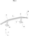
- the pipe member 2 includes two curved portions 21 that are curved (or bent) in the middle of the pipe member 2 in a longitudinal direction. Then, the pipe member 2 is supported by a crash box 101 on the negative side of each of the curved portions 21 in the X-axis direction.
- the pipe member 2 is not limited to being applied to the front bumper, but may be applied to a rear bumper.
- the pipe member 2 includes a pipe portion 22 forming a pipe shape and a flange portion (upper flange portion) 23A and a flange portion (lower flange portion) 23B that are integrally formed to protrude from an outer peripheral portion of the pipe portion 22.
- the pipe member 2 is formed by shaping one base material 2' having a cylindrical shape. Then, after this shaping, the pipe member 2 is in a state where the pipe portion 22, the flange portion 23A, and the flange portion 23B are continuously formed. As described above, the pipe member 2 is formed of one member. Accordingly, in the pipe member 2, the mechanical strength against external force is, for example, 1.5 times or more higher than the mechanical strength of the pipe member 2 formed of, for example, a joint body formed by joining a plurality of members.
- the pipe portion 22 has a higher occupancy ratio (volume ratio) than that of the flange portion 23A or the flange portion 23B in the pipe member 2.
- the pipe portion 22 includes a first recessed portion 221 provided on the positive side in the X-axis direction and a second recessed portion 222 provided on the negative side in the X-axis direction.
- the first recessed portion 221 is recessed and deformed toward the negative side in the X-axis direction and is formed in a groove shape along a center axis O22 direction of the pipe portion 22.
- the second recessed portion 222 is recessed and deformed toward the positive side in the X-axis direction and, similarly to the first recessed portion 221, is formed in a groove shape along the center axis O22 direction of the pipe portion 22.
- the pipe portion 22 has a non-circular pipe shape (ring shape) having a rounded cross-sectional shape because of the first recessed portion 221 and the second recessed portion 222 having such shapes. Accordingly, the mechanical strength of the pipe member 2 can be improved.
- a magnitude relationship in depth or a magnitude relationship in width between the first recessed portion 221 and the second recessed portion 222 is not particularly limited.
- the flange portion 23A is provided on an upper side of the pipe portion 22, and the flange portion 23B is provided on a lower side. Then, the flange portion 23A and the flange portion 23B are formed to protrude in opposite directions. Namely, the flange portion 23A is formed to protrude upward (the positive side in the Z-axis direction), and the flange portion 23B is formed to protrude downward (the negative side in the Z-axis direction). Accordingly, the pipe member 2 has a vertically symmetrical shape and thus can be used even when the pipe member 2 is turned upside down (regardless of an up-down direction).
- the pipe member 2 is used in the automobile 100 in a state where a protruding direction of the flange portion 23A faces upward and a protruding direction of the flange portion 23B faces downward.
- the flange portion 23A and the flange portion 23B are located on a foremost surface of the pipe member 2, together with the pipe portion 22. Because of such a usage state, for example, when the automobile 100 collides head-on, an impact of the collision can be received in as wide an area (range) as possible, so that deformation such as unintentional bending of the pipe member 2 can be sufficiently prevented or prevented. Accordingly, the safety of passengers of the automobile 100 is secured.
- the flange portion 23A is an overlapping portion in which the base material 2' that becomes the pipe member 2 is crushed and parts of a pipe wall of the base material 2' overlap each other in the X-axis direction. Accordingly, the mechanical strength of the flange portion 23A itself is improved. Incidentally, the parts of the pipe wall may be in contact with each other or may be separated from each other.
- the flange portion 23A is formed in a plate shape over a full length of the pipe portion 22 along the center axis O22 direction of the pipe portion 22. Accordingly, the pipe member 2 secures a uniform mechanical strength along the longitudinal direction and thus can sufficiently receive an impact regardless of collision location.
- the protrusion amount C is preferably in a range of from smaller one of 0.5 times the thickness T and 1 mm to 20 times the thickness, more preferably 1 mm to 50 mm. Accordingly, when the pipe member 2 is shaped from the base material 2', the flange portion 23A can be sufficiently formed by bending the pipe wall of the base material 2' without excess or deficiency.
- the protrusion amount C is preferably in a range of from smaller one of 0.01 times a maximum value of the width W and 1 mm to 1 time the maximum value, more preferably 1 mm to 50 mm.
- the pipe member 2 is mounted in the automobile 100, in a case where a length (width) of the pipe member 2 in the Z-axis direction has been determined, it is preferable that as large the width W (maximum value) as possible is secured.
- Each of the first wire-shaped body 3A and the second wire-shaped body 3B is a wire-shaped body having flexibility. As shown in Fig. 3 , in the present embodiment, as one example, the first wire-shaped body 3A is thinner than the second wire-shaped body 3B.
- the first wire-shaped body 3A and the second wire-shaped body 3B are not particularly limited, and examples thereof include an electric cable (harness), a tube, and the like.
- the harness is also called a wire harness.
- examples of the tube include tubes for supplying various liquids such as cooling water, oil, and a washer liquid and the like.
- Both the first wire-shaped body 3A and the second wire-shaped body 3B are disposed in at least one of a first state where the first wire-shaped body 3A and the second wire-shaped body 3B are disposed along the flange portion 23A (flange portion 23B) and a second state where the first wire-shaped body 3A and the second wire-shaped body 3B stride over the flange portion 23A or the flange portion 23B.
- the first wire-shaped body 3A is disposed in the first state outside of the pipe portion 22.
- the second wire-shaped body 3B is disposed in the first state inside the pipe portion 22.
- each of the first wire-shaped body 3A and the second wire-shaped body 3B may meander.
- the flange portion 23A includes an end portion 231 that is rounded along a circumferential direction of the pipe member 2.
- the pipe portion 22 includes a plurality of rounded portions 223 that are rounded along the circumferential direction, at an outer peripheral portion and at an inner peripheral portion.
- the reason that the pipe member 2 has a rounded shape as a whole is that the pipe member 2 is formed by shaping one base material 2' having a cylindrical shape.
- a traveling structure 102 such as a radiator or a battery used for the traveling of the automobile 100 is disposed on the negative side of the pipe member 2 in the X-axis direction.
- a dead space 103 between the traveling structure 102 and the flange portion 23A of the pipe member 2 can be used to dispose the first wire-shaped body 3A in the dead space 103.
- the first wire-shaped body 3A is desired to be disposed away from the traveling structure 102, it is preferable that the first wire-shaped body 3A is disposed close to the flange portion 23A.
- the flange portion 23A includes the end portion 231 that is rounded. Accordingly, even when the first wire-shaped body 3A in the first state is disposed close to the flange portion 23A outside the pipe portion 22, damage to the first wire-shaped body 3A caused by contact with the end portion 231 is prevented. Therefore, in the vehicle structure 1, as long as the first wire-shaped body 3A is separated from the traveling structure 102, the first wire-shaped body 3A can be freely disposed regardless of the position on the pipe portion 22, namely, the degree of freedom in the disposition of the first wire-shaped body 3A with respect to the pipe member 2 is high.
- a highest point HP of the first wire-shaped body 3A is the same as or lower than the height of the end portion 231 of the flange portion 23A. Accordingly, the first wire-shaped body 3A can be protected by the flange portion 23A.
- the first wire-shaped body 3A is fixed using a clamp member or the like. Accordingly, the positional shift of the first wire-shaped body 3A is prevented even while the automobile 100 travels.
- the second wire-shaped body 3B can be freely disposed regardless of the position inside the pipe portion 22, namely, the degree of freedom in the disposition of the second wire-shaped body 3B with respect to the pipe member 2 is high.
- the second wire-shaped body 3B is fixed using a clamp member or the like. Accordingly, the positional shift of the second wire-shaped body 3B is prevented even while the automobile 100 travels.
- the shaping device 5A includes an upper die 51, a lower die 52, a gas supply portion 53, a heating portion 54, a cooling portion 55, a drive unit 56, and a control unit 57.
- the lower die 52 is fixed and the upper die 51 is supported so as to be able to approach and separate from the lower die 52.
- the base material 2' can be disposed between the upper die 51 and the lower die 52.
- the upper die 51 and the lower die 52 in a die clamping state, can define a first cavity 58 for forming the pipe portion 22, a second cavity 59A for forming the flange portion 23A, and a second cavity 59B for forming the flange portion 23B.
- the gas supply portion 53 supplies high-pressure air into the base material 2'.
- the gas supply portion 53 is not particularly limited in terms of configuration and can be configured to include, for example, a compressor.
- the heating portion 54 heats the base material 2'.
- the heating portion 54 is not particularly limited in terms of configuration and can be configured to include, for example, two electrodes that are electrically connected to the base material 2' and a voltage application unit that applies a voltage between the electrodes. Accordingly, the base material 2' can be heated and softened by energizing the base material 2'.
- the cooling portion 55 rapidly cools the pipe member 2 (base material 2').
- the cooling portion 55 is not particularly limited in terms of configuration and can be configured to include, for example, a flow path which is provided in each of the upper die 51 and the lower die 52 and through which a refrigerant passes. Then, when the refrigerant passes through the flow paths, the pipe member 2 can be rapidly cooled on each of the upper die 51 and the lower die 52.
- the refrigerant may be either of a liquid and a gas.
- the cooling portion 55 is built in, for example, the lower die 52. Accordingly, the rapid cooling of the pipe member 2 can be quickly performed.
- the drive unit 56 can move the upper die 51 to cause the upper die 51 to approach and separate from the lower die 52. Accordingly, switching between the die opening state and the die clamping state can be performed.
- the drive unit 56 is not particularly limited in terms of configuration and can be configured to include, for example, a motor, a ball screw connected to the motor, and a linear guide connected to the ball screw.
- the control unit 57 controls operation of the gas supply portion 53, the heating portion 54, the cooling portion 55, and the drive unit 56.
- the control unit 57 is not particularly limited in terms of configuration and can be configured to include, for example, a central processing unit (CPU) and various memories.
- the shaping device 5A operates as follows.
- the upper die 51 and the lower die 52 are set to the die opening state, and the base material 2' is disposed between the upper die 51 and the lower die 52.
- the heating portion 54 is operated in the die opening state. Accordingly, the base material 2' can be softened.
- the upper die 51 is approached to the lower die 52.
- This state has not reached the die clamping state shown in Fig. 6 and is a state where a gap is formed between the upper die 51 and the lower die 52.
- the gas supply portion 53 is operated to perform primary blowing. Accordingly, a part of the base material 2' bulges and enters the gap between the upper die 51 and the lower die 52. The bulged part of the base material 2' becomes the flange portion 23A and the flange portion 23B later.
- the upper die 51 and the lower die 52 are set to the die clamping state shown in Fig. 6 . Accordingly, the flange portion 23A and the flange portion 23B are formed. Then, the gas supply portion 53 is operated to perform secondary blowing. Accordingly, the base material 2' can be deformed into the shape of the pipe member 2, namely, becomes the pipe member 2 including the pipe portion 22, the flange portion 23A, and the flange portion 23B.
- the pipe member 2 is rapidly cooled by the cooling portion 55 in synchronization with the setting of the die clamping state. Accordingly, austenite is transformed into martensite in the pipe member 2.
- the die opening state is set again and the pipe member 2 is extracted. Thereafter, the pipe member 2 can be cut to a desired length and used for the bumper of the automobile 100.
- each flange portion has a different configuration.
- the flange portion 23A includes two flange portions of which protrusion amounts (widths) from the outer peripheral portion of the pipe portion 22 are different from each other (the same also applies to the flange portion 23B).
- the flange portion 23A includes a first flange portion 232 having a large protrusion amount and a second flange portion 233 having a small protrusion amount.
- the small protrusion amount also includes a case where the protrusion amount is zero.
- first flange portions 232 are formed and one second flange portion 233 is formed between the two first flange portions 232, but the formation mode is not limited to this configuration.
- first wire-shaped bodies 3A are disposed in the first state outside the pipe portion 22.
- the first wire-shaped bodies 3A are referred to as a "first wire-shaped body 3A-1", a “first wire-shaped body 3A-2", and a "first wire-shaped body 3A-3".
- the first wire-shaped body 3A-1 to the first wire-shaped body 3A-3 are bundled and routed from the negative side toward the positive side in the Y-axis direction, the first wire-shaped body 3A-2 and the first wire-shaped body 3A-3 are collectively routed toward the negative side in the X-axis direction in the middle, and thereafter, the first wire-shaped body 3A-1 is additionally routed toward the negative side in the X-axis direction.
- the number of the first wire-shaped bodies 3A on the first flange portion 232 can be set to 3 (refer to Fig. 8 ), and the number of the first wire-shaped bodies 3A on the second flange portion 233 can be set to 1 (refer to Fig. 9 ).
- the number of the first wire-shaped bodies 3A (total thickness) on the first flange portion 232 having a large protrusion amount is larger than the number of the first wire-shaped bodies 3A (total thickness) on the second flange portion 233 having a small protrusion amount. Accordingly, each of the first flange portion 232 and the second flange portion 233 can protect the first wire-shaped bodies 3A without excess or deficiency.
- a shaping device 5B is used in the manufacturing method.
- differences between the shaping device 5B and the shaping device 5A will be mainly described, and a description of the same items will be omitted.
- the shaping device 5B is the same as that of the first embodiment except that each of the upper die 51 and the lower die 52 has a different configuration.
- Figs. 10 , 11A, and 11B are cross-sectional views when the shaping device 5B is cut at two different locations in the middle of the pipe member 2 (base material 2') in the longitudinal direction.
- the base material 2' includes a large-diameter portion 24 and a small-diameter portion 25 that are different in outer diameter and inner diameter from each other, along the longitudinal direction.
- the upper die 51 and the lower die 52 share a first shaping portion 501 and a second shaping portion 502.
- the first shaping portion 501 can shape the large-diameter portion 24 into the pipe portion 22 and the first flange portion 232 between the upper die 51 and the lower die 52.
- the second shaping portion 502 can shape the small-diameter portion 25 into the pipe portion 22 and the second flange portion 233 between the upper die 51 and the lower die 52.
- the shaping device 5B operates as follows.
- the upper die 51 and the lower die 52 are set to a die opening state, and the base material 2' is disposed between the upper die 51 and the lower die 52.
- the large-diameter portion 24 is disposed on the first shaping portion 501
- the small-diameter portion 25 is disposed on the second shaping portion 502.
- the upper die 51 and the lower die 52 are set to a die clamping state while operating the gas supply portion 53, the heating portion 54, the cooling portion 55, and the drive unit 56.
- the first cavity 58 for shaping the pipe portion 22 and a second cavity 59A-1 and a second cavity 59B-1 for shaping the first flange portions 232 are defined. Accordingly, the pipe portion 22 and the first flange portions 232 are shaped.
- the first cavity 58 for shaping the pipe portion 22 and a second cavity 59A-2 and a second cavity 59B-2 for shaping the second flange portions 233 are defined. Accordingly, the pipe portion 22 and the second flange portions 233 are shaped.
- the pipe member 2 is a member including the first flange portions 232 and the second flange portions 233.
- the present embodiment is the same as the first embodiment except that the application location of the vehicle structure in the automobile and a disposition state of the first wire-shaped body are different.
- the vehicle structure 1 is disposed on a side lower portion of the automobile 100, and the pipe member 2 is applied to a side sill of the automobile 100.
- the vehicle structure 1 includes a reinforcement member 4 that reinforces the pipe member 2.
- the reinforcement member 4 is joined to the positive side of the pipe member 2 in the Y-axis direction, namely, to an inner side of the vehicle.
- the reinforcement member 4 is formed by bending a plate member, and includes a pipe shape forming portion 41 forming a pipe shape between the pipe shape forming portion 41 and the pipe member 2, a flange portion (bent portion) 42A formed by bending an upper edge portion of the pipe shape forming portion 41, and a flange portion (bent portion) 42B formed by bending a lower edge portion of the pipe shape forming portion 41.
- the pipe shape forming portion 41 includes a recessed portion 411.
- the recessed portion 411 is recessed and deformed toward the negative side in the Y-axis direction and, similarly to the second recessed portion 222 of the pipe portion 22, is formed in a groove shape along the center axis O22 direction of the pipe portion 22.
- the pipe shape forming portion 41 includes a plurality of rounded portions 412 that are rounded on an outer side thereof.
- the flange portion 42A is joined to the flange portion 23A of the pipe member 2, and the flange portion 42B is joined to the flange portion 23B of the pipe member 2.
- the joining method is not particularly limited and, for example, spot welding can be used.
- the flange portion 42A is lower than the flange portion 23A.
- the flange portion 42B is lower than the flange portion 23B.
- the first wire-shaped body 3A is disposed in at least one of the first state where the first wire-shaped body 3A is disposed along the flange portion 23A and the second state where the first wire-shaped body 3A strides over the flange portion 23A. As shown in Figs. 13 and 14 , in the present embodiment, the first wire-shaped body 3A is disposed in the second state outside the pipe portion 22 and accordingly, can stride over the flange portion 42A.
- the flange portion 23A includes the end portion 231 that is rounded. Accordingly, even when the first wire-shaped body 3A is disposed in the second state, damage to the first wire-shaped body 3A caused by contact with the end portion 231 can be prevented. Therefore, in the vehicle structure 1, the first wire-shaped body 3A can be freely disposed regardless of the position on the pipe portion 22, namely, the degree of freedom in the disposition of the first wire-shaped body 3A with respect to the pipe member 2 is high.
- the flange portion 42A is lower than the flange portion 23A, namely, has a smaller protrusion amount than that of the flange portion 23A. Accordingly, as shown in Fig. 14 , even when the first wire-shaped body 3A is disposed in the second state, the first wire-shaped body 3A can be separated from the flange portion 42A. Therefore, damage to the first wire-shaped body 3A caused by contact with the flange portion 42A can be prevented.
- the present embodiment is the same as the third embodiment except that the vehicle structure has a different configuration.
- the vehicle structure 1 includes two pipe members 2.
- the pipe members 2 one flange portion 23A and the other flange portion 23A are joined to each other, and one flange portion 23B and the other flange portion 23B are joined to each other. Accordingly, the pipe members 2 can reinforce each other. Therefore, the mechanical strength of the vehicle structure 1 can be increased.
- the present embodiment is the same as the fourth embodiment except that the pipe member has a different configuration (cross-sectional shape).
- the pipe member 2 has a form in which the two pipe members 2 in the fourth embodiment are formed of one member.
- the flange portion 23A and the flange portion 23B each are formed at central portions of the pipe portion 22 in the Y-axis direction.
- each portion forming the vehicle structure can be replaced with any configuration capable of exhibiting the same function.
- any component may be added.
- vehicle structure of the present invention may be a combination of any two or more configurations (features) in each of the embodiments.
- the vehicle structure 1 is mounted and used in the passenger vehicle in each of the embodiments, but the present invention is not limited thereto, and the vehicle structure 1 can also be mounted and used in vehicles other than the passenger vehicle.
- the other vehicles are not particularly limited and examples thereof include a construction vehicle such as a dump vehicle or an excavator, a vehicle for passenger railway or freight railway, and the like.
- the number of the pipe members included in the vehicle structure is 1 or 2 in each of the embodiments, but the number of the pipe members is not limited thereto and may be, for example, 3 or more.
- the pipe member mounted in the passenger vehicle is applied to a bumper reinforcement or a side sill in each of the embodiments, but the pipe member is not limited to this application and is applicable to, for example, a side roof rail or a steering member (instrument panel reinforcement).
- the number of the wire-shaped bodies included in the vehicle structure is 1 or 2 in each of the embodiments, but the number of the wire-shaped bodies is not limited thereto and may be, for example, 3 or more.
- the formation number of the flange portions included in the pipe member is not limited to 2 in each of the embodiments and may be, for example, 1 or 3 or more.
- the wire-shaped body is disposed in one of the first state and the second state in each of the embodiments, but the wire-shaped body is not limited thereto and may be disposed in a state including both the first state and the second state.
Landscapes
- Engineering & Computer Science (AREA)
- Mechanical Engineering (AREA)
- Chemical & Material Sciences (AREA)
- Combustion & Propulsion (AREA)
- Transportation (AREA)
- Physics & Mathematics (AREA)
- Fluid Mechanics (AREA)
- Body Structure For Vehicles (AREA)
- Shaping Metal By Deep-Drawing, Or The Like (AREA)
Description
- The present invention relates to a vehicle structure.
- In the related art, a bumper that receives an impact at the time of collision is provided on each of the front and the rear of an automobile. As the bumper, for example, a bumper including a bumper reinforcement extending in a vehicle width direction and a crash box that supports the bumper reinforcement has been known (for example, refer to PTL 1). Two bumper reinforcements disclosed in
PTL 1 are disposed on upper and lower sides. Then, the bumper reinforcement on the upper side has, for example, a constant cross section of a substantially eye shape and is made of an extruded aluminum material.PTL 2 discloses a tunnel reinforcement device capable of strengthening a tunnel floor, and which provides support for cables and pipes, while at least partially protecting the cables and pipes. -
- [PTL 1]
Japanese Unexamined Patent Publication No. 2009-56857 - [PTL 2]
European Patent Publication No. 1253067 - A protrusion protruding outward (upward or downward) and including a sharp edge is formed in the bumper reinforcement on the upper side (refer to a "first bumper reinforcement 17" in
Figs. 1 and2 of PTL 1). For this reason, when a cable (harness) is routed, in order to prevent damage to the cable caused by contact with the edge, the cable should be separated from the protrusion as much as possible, and a disposition location of the cable is limited by that amount, which is a problem. - An object of the present invention is to provide a vehicle structure in which the degree of freedom in the disposition of a wire-shaped body with respect to a pipe member is high.
- The invention is defined by the appended
independent claim 1. Additional embodiments are defined in the dependent claims. - One aspect of a vehicle structure of the present invention includes: a pipe member forming a part of a frame of a vehicle; and a wire-shaped body having flexibility.
- The pipe member includes a pipe portion forming a pipe shape and a flange portion formed to protrude from the pipe portion, and is formed of one member in which the pipe portion and the flange portion are continuous with each other.
- The wire-shaped body is disposed in at least one of a first state where the wire-shaped body is disposed along the flange portion and a second state where the wire-shaped body strides over the flange portion.
- The flange portion is an overlapping portion in which a base material that becomes the pipe member is crushed and parts of a pipe wall of the base material overlap each other in a direction perpendicular to a center axis direction of the pipe portion.
- According to the present invention, since the pipe member is formed of one member in which the pipe portion and the flange portion are continuous with each other, the pipe member has a rounded shape as a whole. Accordingly, even when the wire-shaped body is disposed in one of the first state and the second state, damage to the wire-shaped body caused by contact with the flange portion is prevented. Accordingly, the wire-shaped body can be freely disposed regardless of the position with respect to the pipe portion, namely, the degree of freedom in the disposition of the wire-shaped body with respect to the pipe member is high.
-
-
Fig. 1 is a perspective view showing one example of an automobile into which a vehicle structure (first embodiment) of the present invention is built. -
Fig. 2 is a perspective view of the vehicle structure inFig. 1 . -
Fig. 3 is a cross-sectional view taken along line A-A inFig. 2 . -
Fig. 4 is an enlarged view of a region [B] surrounded by an alternate long and short dashed line inFig. 3 . -
Fig. 5 is a view (die opening state) showing a process (one example) of manufacturing a pipe member included in the vehicle structure shown inFig. 2 , in order. -
Fig. 6 is a view (die clamping state) showing the process (one example) of manufacturing the pipe member included in the vehicle structure shown inFig. 2 , in order. -
Fig. 7 is a perspective view showing a second embodiment of the vehicle structure of the present invention. -
Fig. 8 is a cross-sectional view taken along line C-C inFig. 7 . -
Fig. 9 is a cross-sectional view taken along line D-D inFig. 7 . -
Fig. 10 is a view (die opening state) showing a process (one example) of manufacturing a pipe member included in the vehicle structure shown inFig. 7 , in order. -
Figs. 11A and 11B are views (die opening state) showing the process (one example) of manufacturing the pipe member included in the vehicle structure shown inFig. 7 , in order. -
Fig. 12 is a perspective view showing one example of an automobile into which a vehicle structure (third embodiment) of the present invention is built. -
Fig. 13 is a cross-sectional view taken along line E-E inFig. 12 . -
Fig. 14 is an enlarged view of a region [F] surrounded by an alternate long and short dashed line inFig. 13 . -
Fig. 15 is a cross-sectional view showing a fourth embodiment of the vehicle structure of the present invention. -
Fig. 16 is a cross-sectional view showing a fifth embodiment of the vehicle structure of the present invention. - Hereinafter, a vehicle structure of the present invention will be described in detail based on exemplary embodiments shown in the accompanying drawings.
- A first embodiment of the vehicle structure of the present invention will be described with reference to
Figs. 1 to 6 . Incidentally, hereinafter, for convenience of description, a full length direction of a vehicle is an X-axis direction, a vehicle width direction of the vehicle is a Y-axis direction, and a vehicle height direction of the vehicle is a Z-axis direction. In addition, a positive side in the X-axis direction is a front side of the vehicle, a negative side in the X-axis direction is a rear side of the vehicle, a positive side in the Y-axis direction is a right side of the vehicle, a negative side in the Y-axis direction is a left side of the vehicle, a positive side in the Z-axis direction is an upper side of the vehicle, and a negative side in the Z-axis direction is a lower side of the vehicle. - As shown in
Figs. 1 and2 , in the present embodiment, avehicle structure 1 is mounted and used in anautomobile 100 that is a passenger vehicle. As shown inFig. 3 , thevehicle structure 1 includes apipe member 2, a first wire-shaped body 3A, and a second wire-shaped body 3B. - The
pipe member 2 is a member that is disposed parallel to an X-Y plane to form a part of a frame of the vehicle. In the present embodiment, thepipe member 2 is applied to a front bumper of the automobile (passenger vehicle) 100. In this case, thepipe member 2 is called, for example, a "bumper reinforcement" or a "bumper beam" . In addition, thepipe member 2 may be used as a "first bumper" that receives an impact generated at the time of collision from the positive side in the X-axis direction, or may be used as a "second bumper (leg protection beam) that prevents an obstacle or the like from intruding from the positive side in the X-axis direction. - As shown in
Fig. 2 , thepipe member 2 includes twocurved portions 21 that are curved (or bent) in the middle of thepipe member 2 in a longitudinal direction. Then, thepipe member 2 is supported by acrash box 101 on the negative side of each of thecurved portions 21 in the X-axis direction. - Incidentally, the
pipe member 2 is not limited to being applied to the front bumper, but may be applied to a rear bumper. - As shown in
Fig. 3 , thepipe member 2 includes apipe portion 22 forming a pipe shape and a flange portion (upper flange portion) 23A and a flange portion (lower flange portion) 23B that are integrally formed to protrude from an outer peripheral portion of thepipe portion 22. - As will be described later, the
pipe member 2 is formed by shaping one base material 2' having a cylindrical shape. Then, after this shaping, thepipe member 2 is in a state where thepipe portion 22, theflange portion 23A, and theflange portion 23B are continuously formed. As described above, thepipe member 2 is formed of one member. Accordingly, in thepipe member 2, the mechanical strength against external force is, for example, 1.5 times or more higher than the mechanical strength of thepipe member 2 formed of, for example, a joint body formed by joining a plurality of members. - The
pipe portion 22 has a higher occupancy ratio (volume ratio) than that of theflange portion 23A or theflange portion 23B in thepipe member 2. Thepipe portion 22 includes a first recessedportion 221 provided on the positive side in the X-axis direction and a second recessedportion 222 provided on the negative side in the X-axis direction. - The first recessed
portion 221 is recessed and deformed toward the negative side in the X-axis direction and is formed in a groove shape along a center axis O22 direction of thepipe portion 22. - The second recessed
portion 222 is recessed and deformed toward the positive side in the X-axis direction and, similarly to the first recessedportion 221, is formed in a groove shape along the center axis O22 direction of thepipe portion 22. - The
pipe portion 22 has a non-circular pipe shape (ring shape) having a rounded cross-sectional shape because of the first recessedportion 221 and the second recessedportion 222 having such shapes. Accordingly, the mechanical strength of thepipe member 2 can be improved. - Incidentally, a magnitude relationship in depth or a magnitude relationship in width between the first recessed
portion 221 and the second recessedportion 222 is not particularly limited. - The
flange portion 23A is provided on an upper side of thepipe portion 22, and theflange portion 23B is provided on a lower side. Then, theflange portion 23A and theflange portion 23B are formed to protrude in opposite directions. Namely, theflange portion 23A is formed to protrude upward (the positive side in the Z-axis direction), and theflange portion 23B is formed to protrude downward (the negative side in the Z-axis direction). Accordingly, thepipe member 2 has a vertically symmetrical shape and thus can be used even when thepipe member 2 is turned upside down (regardless of an up-down direction). - As shown in
Fig. 3 , in the present embodiment, thepipe member 2 is used in theautomobile 100 in a state where a protruding direction of theflange portion 23A faces upward and a protruding direction of theflange portion 23B faces downward. In addition, theflange portion 23A and theflange portion 23B are located on a foremost surface of thepipe member 2, together with thepipe portion 22. Because of such a usage state, for example, when theautomobile 100 collides head-on, an impact of the collision can be received in as wide an area (range) as possible, so that deformation such as unintentional bending of thepipe member 2 can be sufficiently prevented or prevented. Accordingly, the safety of passengers of theautomobile 100 is secured. - Since the
flange portion 23A and theflange portion 23B have the same configuration except that the locations of formation are different from each other, theflange portion 23A will be representatively described. - The
flange portion 23A is an overlapping portion in which the base material 2' that becomes thepipe member 2 is crushed and parts of a pipe wall of the base material 2' overlap each other in the X-axis direction. Accordingly, the mechanical strength of theflange portion 23A itself is improved. Incidentally, the parts of the pipe wall may be in contact with each other or may be separated from each other. - The
flange portion 23A is formed in a plate shape over a full length of thepipe portion 22 along the center axis O22 direction of thepipe portion 22. Accordingly, thepipe member 2 secures a uniform mechanical strength along the longitudinal direction and thus can sufficiently receive an impact regardless of collision location. - In addition, when a protrusion amount of the
flange portion 23A is C and a thickness of the pipe wall of thepipe member 2 is T, the protrusion amount C is preferably in a range of from smaller one of 0.5 times the thickness T and 1 mm to 20 times the thickness, more preferably 1 mm to 50 mm. Accordingly, when thepipe member 2 is shaped from the base material 2', theflange portion 23A can be sufficiently formed by bending the pipe wall of the base material 2' without excess or deficiency. - In addition, when a width of the
pipe portion 22 along the protruding direction of theflange portion 23A is W, the width W gradually decreases toward the negative side in the X-axis direction. Then, the protrusion amount C is preferably in a range of from smaller one of 0.01 times a maximum value of the width W and 1 mm to 1 time the maximum value, more preferably 1 mm to 50 mm. When thepipe member 2 is mounted in theautomobile 100, in a case where a length (width) of thepipe member 2 in the Z-axis direction has been determined, it is preferable that as large the width W (maximum value) as possible is secured. By causing a magnitude relationship between the protrusion amount C and the width W to satisfy the above numerical range, as large the width W as possible can be secured, and the mechanical strength of thepipe member 2 can be improved. - Each of the first wire-shaped
body 3A and the second wire-shapedbody 3B is a wire-shaped body having flexibility. As shown inFig. 3 , in the present embodiment, as one example, the first wire-shapedbody 3A is thinner than the second wire-shapedbody 3B. Incidentally, the first wire-shapedbody 3A and the second wire-shapedbody 3B are not particularly limited, and examples thereof include an electric cable (harness), a tube, and the like. The harness is also called a wire harness. In addition, examples of the tube include tubes for supplying various liquids such as cooling water, oil, and a washer liquid and the like. - Both the first wire-shaped
body 3A and the second wire-shapedbody 3B are disposed in at least one of a first state where the first wire-shapedbody 3A and the second wire-shapedbody 3B are disposed along theflange portion 23A (flange portion 23B) and a second state where the first wire-shapedbody 3A and the second wire-shapedbody 3B stride over theflange portion 23A or theflange portion 23B. In the configuration shown inFig. 3 , the first wire-shapedbody 3A is disposed in the first state outside of thepipe portion 22. On the other hand, the second wire-shapedbody 3B is disposed in the first state inside thepipe portion 22. Incidentally, each of the first wire-shapedbody 3A and the second wire-shapedbody 3B may meander. - In addition, as shown in
Fig. 4 , theflange portion 23A includes anend portion 231 that is rounded along a circumferential direction of thepipe member 2. Thepipe portion 22 includes a plurality ofrounded portions 223 that are rounded along the circumferential direction, at an outer peripheral portion and at an inner peripheral portion. The reason that thepipe member 2 has a rounded shape as a whole is that thepipe member 2 is formed by shaping one base material 2' having a cylindrical shape. - As shown in
Fig. 3 , for example, a travelingstructure 102 such as a radiator or a battery used for the traveling of theautomobile 100 is disposed on the negative side of thepipe member 2 in the X-axis direction. - Then, a
dead space 103 between the travelingstructure 102 and theflange portion 23A of thepipe member 2 can be used to dispose the first wire-shapedbody 3A in thedead space 103. In this case, since the first wire-shapedbody 3A is desired to be disposed away from the travelingstructure 102, it is preferable that the first wire-shapedbody 3A is disposed close to theflange portion 23A. - As described above, the
flange portion 23A includes theend portion 231 that is rounded. Accordingly, even when the first wire-shapedbody 3A in the first state is disposed close to theflange portion 23A outside thepipe portion 22, damage to the first wire-shapedbody 3A caused by contact with theend portion 231 is prevented. Therefore, in thevehicle structure 1, as long as the first wire-shapedbody 3A is separated from the travelingstructure 102, the first wire-shapedbody 3A can be freely disposed regardless of the position on thepipe portion 22, namely, the degree of freedom in the disposition of the first wire-shapedbody 3A with respect to thepipe member 2 is high. - Incidentally, it is preferable that a highest point HP of the first wire-shaped
body 3A is the same as or lower than the height of theend portion 231 of theflange portion 23A. Accordingly, the first wire-shapedbody 3A can be protected by theflange portion 23A. - In addition, after the first wire-shaped
body 3A is disposed, it is preferable that the first wire-shapedbody 3A is fixed using a clamp member or the like. Accordingly, the positional shift of the first wire-shapedbody 3A is prevented even while theautomobile 100 travels. - Since the plurality of
rounded portions 223 are also formed inside thepipe portion 22, damage to the second wire-shapedbody 3B caused by contact with the inner peripheral portion of thepipe portion 22 is prevented. Accordingly, the second wire-shapedbody 3B can be freely disposed regardless of the position inside thepipe portion 22, namely, the degree of freedom in the disposition of the second wire-shapedbody 3B with respect to thepipe member 2 is high. - In addition, after the second wire-shaped
body 3B is disposed, it is preferable that the second wire-shapedbody 3B is fixed using a clamp member or the like. Accordingly, the positional shift of the second wire-shapedbody 3B is prevented even while theautomobile 100 travels. - Next, a method for manufacturing the
pipe member 2 will be described with reference toFigs. 5 and6 . - In the manufacturing method, a
shaping device 5A is used. Theshaping device 5A includes anupper die 51, alower die 52, agas supply portion 53, aheating portion 54, a coolingportion 55, adrive unit 56, and acontrol unit 57. - The
lower die 52 is fixed and theupper die 51 is supported so as to be able to approach and separate from thelower die 52. As shown inFig. 5 , in a die opening state of theupper die 51 and thelower die 52, the base material 2' can be disposed between theupper die 51 and thelower die 52. In addition, as shown inFig. 6 , in a die clamping state, theupper die 51 and thelower die 52 can define afirst cavity 58 for forming thepipe portion 22, asecond cavity 59A for forming theflange portion 23A, and asecond cavity 59B for forming theflange portion 23B. - The
gas supply portion 53 supplies high-pressure air into the base material 2'. Thegas supply portion 53 is not particularly limited in terms of configuration and can be configured to include, for example, a compressor. - The
heating portion 54 heats the base material 2'. Theheating portion 54 is not particularly limited in terms of configuration and can be configured to include, for example, two electrodes that are electrically connected to the base material 2' and a voltage application unit that applies a voltage between the electrodes. Accordingly, the base material 2' can be heated and softened by energizing the base material 2'. - The cooling
portion 55 rapidly cools the pipe member 2 (base material 2'). The coolingportion 55 is not particularly limited in terms of configuration and can be configured to include, for example, a flow path which is provided in each of theupper die 51 and thelower die 52 and through which a refrigerant passes. Then, when the refrigerant passes through the flow paths, thepipe member 2 can be rapidly cooled on each of theupper die 51 and thelower die 52. Incidentally, the refrigerant may be either of a liquid and a gas. In addition, it is preferable that the coolingportion 55 is built in, for example, thelower die 52. Accordingly, the rapid cooling of thepipe member 2 can be quickly performed. - The
drive unit 56 can move theupper die 51 to cause theupper die 51 to approach and separate from thelower die 52. Accordingly, switching between the die opening state and the die clamping state can be performed. Thedrive unit 56 is not particularly limited in terms of configuration and can be configured to include, for example, a motor, a ball screw connected to the motor, and a linear guide connected to the ball screw. - The
control unit 57 controls operation of thegas supply portion 53, theheating portion 54, the coolingportion 55, and thedrive unit 56. Thecontrol unit 57 is not particularly limited in terms of configuration and can be configured to include, for example, a central processing unit (CPU) and various memories. - The
shaping device 5A operates as follows. - First, as shown in
Fig. 5 , theupper die 51 and thelower die 52 are set to the die opening state, and the base material 2' is disposed between theupper die 51 and thelower die 52. Next, theheating portion 54 is operated in the die opening state. Accordingly, the base material 2' can be softened. - Next, the
upper die 51 is approached to thelower die 52. This state has not reached the die clamping state shown inFig. 6 and is a state where a gap is formed between theupper die 51 and thelower die 52. Then, thegas supply portion 53 is operated to perform primary blowing. Accordingly, a part of the base material 2' bulges and enters the gap between theupper die 51 and thelower die 52. The bulged part of the base material 2' becomes theflange portion 23A and theflange portion 23B later. - Next, the
upper die 51 and thelower die 52 are set to the die clamping state shown inFig. 6 . Accordingly, theflange portion 23A and theflange portion 23B are formed. Then, thegas supply portion 53 is operated to perform secondary blowing. Accordingly, the base material 2' can be deformed into the shape of thepipe member 2, namely, becomes thepipe member 2 including thepipe portion 22, theflange portion 23A, and theflange portion 23B. - In addition, the
pipe member 2 is rapidly cooled by the coolingportion 55 in synchronization with the setting of the die clamping state. Accordingly, austenite is transformed into martensite in thepipe member 2. - Next, the die opening state is set again and the
pipe member 2 is extracted. Thereafter, thepipe member 2 can be cut to a desired length and used for the bumper of theautomobile 100. - Hereinafter, a second embodiment of the vehicle structure of the present invention will be described with reference to
Figs. 7 to 11B , but differences from the above-described embodiment will be mainly described, and a description of the same items will be omitted. - The present embodiment is the same as the first embodiment except that each flange portion has a different configuration.
- As shown in
Fig. 7 , in the present embodiment, theflange portion 23A includes two flange portions of which protrusion amounts (widths) from the outer peripheral portion of thepipe portion 22 are different from each other (the same also applies to theflange portion 23B). Namely, theflange portion 23A includes afirst flange portion 232 having a large protrusion amount and asecond flange portion 233 having a small protrusion amount. Here, in the present invention, "the small protrusion amount" also includes a case where the protrusion amount is zero. - Incidentally, in the configuration shown in
Fig. 7 , twofirst flange portions 232 are formed and onesecond flange portion 233 is formed between the twofirst flange portions 232, but the formation mode is not limited to this configuration. - In addition, three first wire-shaped
bodies 3A are disposed in the first state outside thepipe portion 22. The first wire-shapedbodies 3A are referred to as a "first wire-shapedbody 3A-1", a "first wire-shapedbody 3A-2", and a "first wire-shapedbody 3A-3". - Then, the first wire-shaped
body 3A-1 to the first wire-shapedbody 3A-3 are bundled and routed from the negative side toward the positive side in the Y-axis direction, the first wire-shapedbody 3A-2 and the first wire-shapedbody 3A-3 are collectively routed toward the negative side in the X-axis direction in the middle, and thereafter, the first wire-shapedbody 3A-1 is additionally routed toward the negative side in the X-axis direction. Accordingly, the number of the first wire-shapedbodies 3A on thefirst flange portion 232 can be set to 3 (refer toFig. 8 ), and the number of the first wire-shapedbodies 3A on thesecond flange portion 233 can be set to 1 (refer toFig. 9 ). - As described above, the number of the first wire-shaped
bodies 3A (total thickness) on thefirst flange portion 232 having a large protrusion amount is larger than the number of the first wire-shapedbodies 3A (total thickness) on thesecond flange portion 233 having a small protrusion amount. Accordingly, each of thefirst flange portion 232 and thesecond flange portion 233 can protect the first wire-shapedbodies 3A without excess or deficiency. - Next, a method for manufacturing the
pipe member 2 will be described with reference toFigs. 10 ,11A and 11B . - In the manufacturing method, a
shaping device 5B is used. Here, differences between the shapingdevice 5B and theshaping device 5A will be mainly described, and a description of the same items will be omitted. Theshaping device 5B is the same as that of the first embodiment except that each of theupper die 51 and thelower die 52 has a different configuration. Incidentally,Figs. 10 ,11A, and 11B are cross-sectional views when theshaping device 5B is cut at two different locations in the middle of the pipe member 2 (base material 2') in the longitudinal direction. - The base material 2' includes a large-
diameter portion 24 and a small-diameter portion 25 that are different in outer diameter and inner diameter from each other, along the longitudinal direction. - The
upper die 51 and thelower die 52 share afirst shaping portion 501 and asecond shaping portion 502. - The
first shaping portion 501 can shape the large-diameter portion 24 into thepipe portion 22 and thefirst flange portion 232 between theupper die 51 and thelower die 52. - The
second shaping portion 502 can shape the small-diameter portion 25 into thepipe portion 22 and thesecond flange portion 233 between theupper die 51 and thelower die 52. - The
shaping device 5B operates as follows. - First, as shown in
Fig. 10 , theupper die 51 and thelower die 52 are set to a die opening state, and the base material 2' is disposed between theupper die 51 and thelower die 52. In this case, the large-diameter portion 24 is disposed on thefirst shaping portion 501, and the small-diameter portion 25 is disposed on thesecond shaping portion 502. - Next, as described above, as shown in
Figs. 11A and 11B , theupper die 51 and thelower die 52 are set to a die clamping state while operating thegas supply portion 53, theheating portion 54, the coolingportion 55, and thedrive unit 56. - In this case, in the
first shaping portion 501, thefirst cavity 58 for shaping thepipe portion 22 and asecond cavity 59A-1 and asecond cavity 59B-1 for shaping thefirst flange portions 232 are defined. Accordingly, thepipe portion 22 and thefirst flange portions 232 are shaped. - On the other hand, in the
second shaping portion 502, thefirst cavity 58 for shaping thepipe portion 22 and asecond cavity 59A-2 and asecond cavity 59B-2 for shaping thesecond flange portions 233 are defined. Accordingly, thepipe portion 22 and thesecond flange portions 233 are shaped. - Then, the die opening state is set again and the
pipe member 2 is extracted. Thepipe member 2 is a member including thefirst flange portions 232 and thesecond flange portions 233. - Hereinafter, a third embodiment of the vehicle structure of the present invention will be described with reference to
Figs. 12 to 14 , but differences from the above-described embodiments will be mainly described, and a description of the same items will be omitted. - The present embodiment is the same as the first embodiment except that the application location of the vehicle structure in the automobile and a disposition state of the first wire-shaped body are different.
- As shown in
Fig. 12 , in the present embodiment, thevehicle structure 1 is disposed on a side lower portion of theautomobile 100, and thepipe member 2 is applied to a side sill of theautomobile 100. - As shown in
Fig. 13 , thevehicle structure 1 includes areinforcement member 4 that reinforces thepipe member 2. Thereinforcement member 4 is joined to the positive side of thepipe member 2 in the Y-axis direction, namely, to an inner side of the vehicle. Thereinforcement member 4 is formed by bending a plate member, and includes a pipeshape forming portion 41 forming a pipe shape between the pipeshape forming portion 41 and thepipe member 2, a flange portion (bent portion) 42A formed by bending an upper edge portion of the pipeshape forming portion 41, and a flange portion (bent portion) 42B formed by bending a lower edge portion of the pipeshape forming portion 41. - The pipe
shape forming portion 41 includes a recessedportion 411. The recessedportion 411 is recessed and deformed toward the negative side in the Y-axis direction and, similarly to the second recessedportion 222 of thepipe portion 22, is formed in a groove shape along the center axis O22 direction of thepipe portion 22. In addition, the pipeshape forming portion 41 includes a plurality ofrounded portions 412 that are rounded on an outer side thereof. - The
flange portion 42A is joined to theflange portion 23A of thepipe member 2, and theflange portion 42B is joined to theflange portion 23B of thepipe member 2. The joining method is not particularly limited and, for example, spot welding can be used. In addition, theflange portion 42A is lower than theflange portion 23A. Similarly, theflange portion 42B is lower than theflange portion 23B. - The first wire-shaped
body 3A is disposed in at least one of the first state where the first wire-shapedbody 3A is disposed along theflange portion 23A and the second state where the first wire-shapedbody 3A strides over theflange portion 23A. As shown inFigs. 13 and14 , in the present embodiment, the first wire-shapedbody 3A is disposed in the second state outside thepipe portion 22 and accordingly, can stride over theflange portion 42A. - As described above, the
flange portion 23A includes theend portion 231 that is rounded. Accordingly, even when the first wire-shapedbody 3A is disposed in the second state, damage to the first wire-shapedbody 3A caused by contact with theend portion 231 can be prevented. Therefore, in thevehicle structure 1, the first wire-shapedbody 3A can be freely disposed regardless of the position on thepipe portion 22, namely, the degree of freedom in the disposition of the first wire-shapedbody 3A with respect to thepipe member 2 is high. - In addition, as described above, the
flange portion 42A is lower than theflange portion 23A, namely, has a smaller protrusion amount than that of theflange portion 23A. Accordingly, as shown inFig. 14 , even when the first wire-shapedbody 3A is disposed in the second state, the first wire-shapedbody 3A can be separated from theflange portion 42A. Therefore, damage to the first wire-shapedbody 3A caused by contact with theflange portion 42A can be prevented. - Hereinafter, a fourth embodiment of the vehicle structure of the present invention will be described with reference to
Fig. 15 , but differences from the above-described embodiments will be mainly described, and a description of the same items will be omitted. - The present embodiment is the same as the third embodiment except that the vehicle structure has a different configuration.
- As shown in
Fig. 15 , in the present embodiment, thevehicle structure 1 includes twopipe members 2. In thepipe members 2, oneflange portion 23A and theother flange portion 23A are joined to each other, and oneflange portion 23B and theother flange portion 23B are joined to each other. Accordingly, thepipe members 2 can reinforce each other. Therefore, the mechanical strength of thevehicle structure 1 can be increased. - Hereinafter, a fifth embodiment of the vehicle structure of the present invention will be described with reference to
Fig. 16 , but differences from the above-described embodiments will be mainly described, and a description of the same items will be omitted. - The present embodiment is the same as the fourth embodiment except that the pipe member has a different configuration (cross-sectional shape).
- As shown in
Fig. 16 , in the present embodiment, thepipe member 2 has a form in which the twopipe members 2 in the fourth embodiment are formed of one member. In this case, theflange portion 23A and theflange portion 23B each are formed at central portions of thepipe portion 22 in the Y-axis direction. With such a configuration, the mechanical strength of thepipe member 2 is increased by the amount that the size of thepipe portion 22 is expanded. - The illustrated embodiments of the vehicle structure have been described above, but the present invention is not limited to the embodiments, and each portion forming the vehicle structure can be replaced with any configuration capable of exhibiting the same function. In addition, any component may be added.
- In addition, the vehicle structure of the present invention may be a combination of any two or more configurations (features) in each of the embodiments.
- In addition, the
vehicle structure 1 is mounted and used in the passenger vehicle in each of the embodiments, but the present invention is not limited thereto, and thevehicle structure 1 can also be mounted and used in vehicles other than the passenger vehicle. The other vehicles are not particularly limited and examples thereof include a construction vehicle such as a dump vehicle or an excavator, a vehicle for passenger railway or freight railway, and the like. - In addition, the number of the pipe members included in the vehicle structure is 1 or 2 in each of the embodiments, but the number of the pipe members is not limited thereto and may be, for example, 3 or more.
- In addition, the pipe member mounted in the passenger vehicle is applied to a bumper reinforcement or a side sill in each of the embodiments, but the pipe member is not limited to this application and is applicable to, for example, a side roof rail or a steering member (instrument panel reinforcement).
- In addition, the number of the wire-shaped bodies included in the vehicle structure is 1 or 2 in each of the embodiments, but the number of the wire-shaped bodies is not limited thereto and may be, for example, 3 or more. In addition, the formation number of the flange portions included in the pipe member is not limited to 2 in each of the embodiments and may be, for example, 1 or 3 or more.
- In addition, the wire-shaped body is disposed in one of the first state and the second state in each of the embodiments, but the wire-shaped body is not limited thereto and may be disposed in a state including both the first state and the second state.
-
- 1 Vehicle structure
- 2 Pipe member
- 2' Base material
- 21 Curved portion
- 22 Pipe portion
- 221 First recessed portion
- 222 Second recessed portion
- 223 Rounded portion
- 23A Flange portion (upper flange portion)
- 23B Flange portion (lower flange portion)
- 231 End portion
- 232 First flange portion
- 233 Second flange portion
- 24 Large-diameter portion
- 25 Small-diameter portion
- 3A First wire-shaped body
- 3A-1 First wire-shaped body
- 3A-2 First wire-shaped body
- 3A-3 First wire-shaped body
- 3B Second wire-shaped body
- 4 Reinforcement member
- 41 Pipe shape forming portion
- 411 Recessed portion
- 412 Rounded portion
- 42A Flange portion (bent portion)
- 42B Flange portion (bent portion)
- 5A Shaping device
- 5B Shaping device
- 501 First shaping portion
- 502 Second shaping portion
- 51 Upper die
- 52 Lower die
- 53 Gas supply portion
- 54 Heating portion
- 55 Cooling portion
- 56 Drive unit
- 57 Control unit
- 58 First cavity
- 59A Second cavity
- 59A-1 Second cavity
- 59A-2 Second cavity
- 59B Second cavity
- 59B-1 Second cavity
- 59B-2 Second cavity
- 100 Automobile (passenger vehicle)
- 101 Crash box
- 102 Traveling structure
- 103 Dead space
- C Protrusion amount
- HP Highest point
- O22 Center axis
- T Thickness
- W Width
Claims (10)
- A vehicle structure (1) comprising:a pipe member (2) forming a part of a frame of a vehicle; anda wire-shaped body (3A, 3B) having flexibility,wherein the pipe member (2) includes a pipe portion (22) forming a pipe shape and a flange portion (23A, 23B) formed to protrude from the pipe portion (22), and is formed of one member in which the pipe portion (22) and the flange portion (23A, 23B) are continuous with each other,the wire-shaped body (3A, 3B) is disposed in at least one of a first state where the wire-shaped body (3A, 3B) is disposed along the flange portion (23A, 23B) and a second state where the wire-shaped body (3A, 3B) strides over the flange portion (23A, 23B), characterized in thatthe flange portion (23A, 23B) is an overlapping portion in which a base material (2') that becomes the pipe member (2) is crushed and parts of a pipe wall of the base material (2') overlap each other in a direction perpendicular to a center axis direction of the pipe portion (22).
- The vehicle structure (1) according to claim 1, wherein the wire-shaped body (3A, 3B) is disposed in the first state outside the pipe portion (22).
- The vehicle structure (1) according to claim 1,
wherein the wire-shaped body (3A, 3B) is disposed in the first state inside the pipe portion (22). - The vehicle structure (1) according to any one of claims 1 to 3,
wherein the flange portion (23A, 23B) is formed along the center axis direction of the pipe portion (22). - The vehicle structure (1) according to any one of claims 1 to 4,
wherein two flange portions (23A, 23B) are formed to protrude in opposite directions. - The vehicle structure (1) according to any one of claims 1 to 5,
wherein the flange portion (23A, 23B) is rounded along a circumferential direction of the pipe member (2). - The vehicle structure (1) according to any one of claims 1 to 6,wherein the flange portion (23A, 23B) includes a first flange portion (232) having a large protrusion amount and a second flange portion (233) having a small protrusion amount, andthe wire-shaped body (3A, 3B) is disposed in the first state, and a thickness or the number of the wire-shaped bodies on the first flange portion (232) is larger than a thickness or the number of the wire-shaped bodies on the second flange portion (233).
- The vehicle structure (1) according to any one of claims 1 to 7, further comprising:a reinforcement member (4) joined to the pipe member (2) to reinforce the pipe member (2),wherein the reinforcement member (4) includes a pipe shape forming portion (41) forming a pipe shape between the pipe shape forming portion (41) and the pipe member (2), and a bent portion (42A, 42B) formed by bending an edge portion of the pipe shape forming portion (41), andthe wire-shaped body (3A, 3B) is disposed in the second state and strides over the bent portion (42A, 42B).
- The vehicle structure (1) according to claim 8,
wherein the bent portion (42A, 42B) has a smaller protrusion amount than a protrusion amount of the flange portion (23A, 23B). - The vehicle structure (1) according to any one of claims 1 to 9,
wherein the pipe member (2) is used in the vehicle in a state where a protruding direction of the flange portion (23A, 23B) faces upward or downward.
Applications Claiming Priority (2)
| Application Number | Priority Date | Filing Date | Title |
|---|---|---|---|
| JP2020078580A JP7763583B2 (en) | 2020-04-27 | 2020-04-27 | Vehicle structures |
| PCT/JP2020/045852 WO2021220546A1 (en) | 2020-04-27 | 2020-12-09 | Vehicle structure |
Publications (3)
| Publication Number | Publication Date |
|---|---|
| EP4144454A1 EP4144454A1 (en) | 2023-03-08 |
| EP4144454A4 EP4144454A4 (en) | 2023-10-25 |
| EP4144454B1 true EP4144454B1 (en) | 2025-05-28 |
Family
ID=78279095
Family Applications (1)
| Application Number | Title | Priority Date | Filing Date |
|---|---|---|---|
| EP20933128.9A Active EP4144454B1 (en) | 2020-04-27 | 2020-12-09 | Vehicle structure |
Country Status (7)
| Country | Link |
|---|---|
| US (1) | US12319215B2 (en) |
| EP (1) | EP4144454B1 (en) |
| JP (2) | JP7763583B2 (en) |
| CN (1) | CN114929526A (en) |
| CA (1) | CA3169600A1 (en) |
| ES (1) | ES3035152T3 (en) |
| WO (1) | WO2021220546A1 (en) |
Families Citing this family (2)
| Publication number | Priority date | Publication date | Assignee | Title |
|---|---|---|---|---|
| JP6665958B1 (en) * | 2019-03-19 | 2020-03-13 | Jfeスチール株式会社 | Joint structure of vehicle body frame parts, vehicle body frame parts, and method of manufacturing the vehicle body frame parts |
| USD1077680S1 (en) * | 2023-07-13 | 2025-06-03 | Volkswagen Aktiengesellschaft | Motor vehicle |
Family Cites Families (30)
| Publication number | Priority date | Publication date | Assignee | Title |
|---|---|---|---|---|
| DE1859944U (en) | 1962-07-06 | 1962-10-11 | Henschel Werke Ag | BUFFER MADE OF RUBBER OR ELASTIC MATERIAL FOR MOTOR VEHICLES. |
| JPS59143776A (en) * | 1983-02-03 | 1984-08-17 | Nissan Motor Co Ltd | Car body structure |
| SE503450C2 (en) * | 1994-01-26 | 1996-06-17 | Plannja Hardtech Ab | Bumper beam |
| FR2824040B1 (en) * | 2001-04-27 | 2003-09-05 | Renault | TUNNEL REINFORCEMENT DEVICE |
| US6739166B1 (en) | 2002-12-17 | 2004-05-25 | General Motors Corporation | Method of forming tubular member with flange |
| JP2006096198A (en) * | 2004-09-29 | 2006-04-13 | Nissan Motor Co Ltd | Vehicle side sill structure |
| WO2009014233A1 (en) * | 2007-07-20 | 2009-01-29 | Nippon Steel Corporation | Hydroforming method, and hydroformed parts |
| JP4914314B2 (en) | 2007-08-30 | 2012-04-11 | アイシン精機株式会社 | Bumper device for vehicle |
| JP4920772B2 (en) * | 2010-06-18 | 2012-04-18 | リンツリサーチエンジニアリング株式会社 | Flanged metal pipe manufacturing apparatus, manufacturing method thereof, and blow mold |
| CN201797277U (en) * | 2010-07-16 | 2011-04-13 | 中国航空工业集团公司西安飞机设计研究所 | Perforated Cable Protection Parts |
| US8668253B2 (en) * | 2012-06-12 | 2014-03-11 | Ford Global Technologies, Llc | Integrated door scuff plate and wire shield |
| JP2014227153A (en) | 2013-05-27 | 2014-12-08 | マツダ株式会社 | Attachment structure of accessory device for vehicle |
| DE102014207745B4 (en) * | 2014-04-24 | 2017-09-07 | Leoni Bordnetz-Systeme Gmbh | Cable duct for a motor vehicle and motor vehicle with such a cable channel |
| JP6314714B2 (en) | 2014-07-14 | 2018-04-25 | トヨタ自動車株式会社 | Bumper structure for vehicles with pedestrian collision detection sensor |
| EP3090923B1 (en) * | 2015-05-08 | 2018-03-21 | Volvo Car Corporation | Sill structure for a motor vehicle |
| DE102015112935A1 (en) * | 2015-08-06 | 2017-02-09 | Benteler Automobiltechnik Gmbh | bumper assembly |
| JP6256427B2 (en) * | 2015-08-10 | 2018-01-10 | トヨタ自動車株式会社 | Bumper structure for vehicles with pedestrian collision detection sensor |
| DE102015114105B4 (en) * | 2015-08-25 | 2018-11-29 | Benteler Automobiltechnik Gmbh | Impact beam for a motor vehicle and method for its production |
| EP3424607B1 (en) * | 2016-03-01 | 2020-11-18 | Sumitomo Heavy Industries, Ltd. | Molding device and molding method |
| CN205681044U (en) * | 2016-06-07 | 2016-11-09 | 唐山市中科英华电力技术有限公司 | One manages and protects mouth |
| US10103528B2 (en) * | 2016-06-30 | 2018-10-16 | Hellermanntyton Corporation | Cable duct |
| JP2019014461A (en) * | 2017-07-11 | 2019-01-31 | トヨタ車体株式会社 | Vehicular bumper |
| CA3101330C (en) | 2018-08-01 | 2023-01-10 | Sumitomo Heavy Industries, Ltd. | Reinforcement member for vehicle, and method for manufacturing same |
| RU187923U9 (en) * | 2018-10-25 | 2019-05-07 | Общество с ограниченной ответственностью "ЭнергоТэк" | PIPE FOR LAYING CABLE LINE WITH PROTECTION OF CABLE SHELL AGAINST MECHANICAL DAMAGE AT END PARTS |
| JP7135803B2 (en) * | 2018-12-04 | 2022-09-13 | トヨタ自動車株式会社 | Front pillar structure |
| JP6704982B2 (en) * | 2018-12-28 | 2020-06-03 | 住友重機械工業株式会社 | Molding equipment |
| JP7382388B2 (en) * | 2019-03-05 | 2023-11-16 | 住友重機械工業株式会社 | Metal pipe forming method, metal pipe, and forming system |
| JP6760539B1 (en) * | 2019-10-09 | 2020-09-23 | 日本製鉄株式会社 | Molded products, structural members using them, and methods for manufacturing molded products |
| JPWO2021149387A1 (en) * | 2020-01-20 | 2021-07-29 | ||
| JP7768177B2 (en) * | 2023-03-30 | 2025-11-12 | 横河電機株式会社 | Apparatus, method and program |
-
2020
- 2020-04-27 JP JP2020078580A patent/JP7763583B2/en active Active
- 2020-12-09 CA CA3169600A patent/CA3169600A1/en active Pending
- 2020-12-09 CN CN202080092322.7A patent/CN114929526A/en active Pending
- 2020-12-09 EP EP20933128.9A patent/EP4144454B1/en active Active
- 2020-12-09 WO PCT/JP2020/045852 patent/WO2021220546A1/en not_active Ceased
- 2020-12-09 ES ES20933128T patent/ES3035152T3/en active Active
-
2022
- 2022-10-25 US US17/973,211 patent/US12319215B2/en active Active
-
2024
- 2024-04-05 JP JP2024061212A patent/JP7742447B2/en active Active
Also Published As
| Publication number | Publication date |
|---|---|
| JP2024091676A (en) | 2024-07-05 |
| WO2021220546A1 (en) | 2021-11-04 |
| EP4144454A4 (en) | 2023-10-25 |
| JP2021172252A (en) | 2021-11-01 |
| KR20230002275A (en) | 2023-01-05 |
| CN114929526A (en) | 2022-08-19 |
| US20230044854A1 (en) | 2023-02-09 |
| CA3169600A1 (en) | 2021-11-04 |
| ES3035152T3 (en) | 2025-08-29 |
| JP7763583B2 (en) | 2025-11-04 |
| US12319215B2 (en) | 2025-06-03 |
| JP7742447B2 (en) | 2025-09-19 |
| EP4144454A1 (en) | 2023-03-08 |
Similar Documents
| Publication | Publication Date | Title |
|---|---|---|
| JP7742447B2 (en) | Pipe members | |
| US9630656B2 (en) | Vehicle body structure | |
| US10407100B2 (en) | Vehicle body frame structure | |
| JP2023515495A (en) | Beam assembly with multiple hollow structures | |
| CN108146512B (en) | Center portion structure for vehicle | |
| US6761375B2 (en) | Structure of reinforcement plate member used in automobile airbag apparatus | |
| US12214825B2 (en) | Flanged member | |
| US10960738B2 (en) | Arrangement with a crash profile and a load transmission element on a motor vehicle, load transmission element and motor vehicle or vehicle door | |
| US11919573B2 (en) | Vehicle body structure, reinforcement member, and reinforcement member manufacturing method | |
| KR102955226B1 (en) | Vehicle structure | |
| JP3632654B2 (en) | Body front structure | |
| JP5820455B2 (en) | Vehicle rear structure | |
| JP7350610B2 (en) | Vehicle bumper, bumper member, and method for manufacturing bumper member | |
| US20250058729A1 (en) | Crash box for a bumper arrangement of a motor vehicle and a bumper arrangement of a motor vehicle with two such crash boxes and a method for producing such a bumper arrangement | |
| EP4400371A1 (en) | Crash management system | |
| JP6084544B2 (en) | Manufacturing method of frame member for automobile | |
| JP2024009642A (en) | Vehicles with impact beams | |
| JP6661572B2 (en) | Car pillar top | |
| CN121084499A (en) | Lower structure of vehicle |
Legal Events
| Date | Code | Title | Description |
|---|---|---|---|
| STAA | Information on the status of an ep patent application or granted ep patent |
Free format text: STATUS: THE INTERNATIONAL PUBLICATION HAS BEEN MADE |
|
| PUAI | Public reference made under article 153(3) epc to a published international application that has entered the european phase |
Free format text: ORIGINAL CODE: 0009012 |
|
| STAA | Information on the status of an ep patent application or granted ep patent |
Free format text: STATUS: REQUEST FOR EXAMINATION WAS MADE |
|
| 17P | Request for examination filed |
Effective date: 20220719 |
|
| AK | Designated contracting states |
Kind code of ref document: A1 Designated state(s): AL AT BE BG CH CY CZ DE DK EE ES FI FR GB GR HR HU IE IS IT LI LT LU LV MC MK MT NL NO PL PT RO RS SE SI SK SM TR |
|
| DAV | Request for validation of the european patent (deleted) | ||
| DAX | Request for extension of the european patent (deleted) | ||
| STAA | Information on the status of an ep patent application or granted ep patent |
Free format text: STATUS: EXAMINATION IS IN PROGRESS |
|
| A4 | Supplementary search report drawn up and despatched |
Effective date: 20230921 |
|
| RIC1 | Information provided on ipc code assigned before grant |
Ipc: B62D 25/20 20060101ALI20230915BHEP Ipc: B21D 26/033 20110101ALI20230915BHEP Ipc: B60R 19/04 20060101ALI20230915BHEP Ipc: B21D 53/88 20060101ALI20230915BHEP Ipc: B21D 22/26 20060101AFI20230915BHEP |
|
| 17Q | First examination report despatched |
Effective date: 20231004 |
|
| GRAP | Despatch of communication of intention to grant a patent |
Free format text: ORIGINAL CODE: EPIDOSNIGR1 |
|
| STAA | Information on the status of an ep patent application or granted ep patent |
Free format text: STATUS: GRANT OF PATENT IS INTENDED |
|
| INTG | Intention to grant announced |
Effective date: 20241220 |
|
| GRAS | Grant fee paid |
Free format text: ORIGINAL CODE: EPIDOSNIGR3 |
|
| GRAA | (expected) grant |
Free format text: ORIGINAL CODE: 0009210 |
|
| STAA | Information on the status of an ep patent application or granted ep patent |
Free format text: STATUS: THE PATENT HAS BEEN GRANTED |
|
| AK | Designated contracting states |
Kind code of ref document: B1 Designated state(s): AL AT BE BG CH CY CZ DE DK EE ES FI FR GB GR HR HU IE IS IT LI LT LU LV MC MK MT NL NO PL PT RO RS SE SI SK SM TR |
|
| REG | Reference to a national code |
Ref country code: GB Ref legal event code: FG4D |
|
| REG | Reference to a national code |
Ref country code: CH Ref legal event code: EP |
|
| REG | Reference to a national code |
Ref country code: IE Ref legal event code: FG4D Ref country code: DE Ref legal event code: R096 Ref document number: 602020052134 Country of ref document: DE |
|
| REG | Reference to a national code |
Ref country code: ES Ref legal event code: FG2A Ref document number: 3035152 Country of ref document: ES Kind code of ref document: T3 Effective date: 20250829 |
|
| REG | Reference to a national code |
Ref country code: NL Ref legal event code: MP Effective date: 20250528 |
|
| PG25 | Lapsed in a contracting state [announced via postgrant information from national office to epo] |
Ref country code: FI Free format text: LAPSE BECAUSE OF FAILURE TO SUBMIT A TRANSLATION OF THE DESCRIPTION OR TO PAY THE FEE WITHIN THE PRESCRIBED TIME-LIMIT Effective date: 20250528 |
|
| REG | Reference to a national code |
Ref country code: LT Ref legal event code: MG9D |
|
| PG25 | Lapsed in a contracting state [announced via postgrant information from national office to epo] |
Ref country code: NO Free format text: LAPSE BECAUSE OF FAILURE TO SUBMIT A TRANSLATION OF THE DESCRIPTION OR TO PAY THE FEE WITHIN THE PRESCRIBED TIME-LIMIT Effective date: 20250828 Ref country code: GR Free format text: LAPSE BECAUSE OF FAILURE TO SUBMIT A TRANSLATION OF THE DESCRIPTION OR TO PAY THE FEE WITHIN THE PRESCRIBED TIME-LIMIT Effective date: 20250829 |
|
| PG25 | Lapsed in a contracting state [announced via postgrant information from national office to epo] |
Ref country code: NL Free format text: LAPSE BECAUSE OF FAILURE TO SUBMIT A TRANSLATION OF THE DESCRIPTION OR TO PAY THE FEE WITHIN THE PRESCRIBED TIME-LIMIT Effective date: 20250528 Ref country code: PL Free format text: LAPSE BECAUSE OF FAILURE TO SUBMIT A TRANSLATION OF THE DESCRIPTION OR TO PAY THE FEE WITHIN THE PRESCRIBED TIME-LIMIT Effective date: 20250528 |
|
| PG25 | Lapsed in a contracting state [announced via postgrant information from national office to epo] |
Ref country code: BG Free format text: LAPSE BECAUSE OF FAILURE TO SUBMIT A TRANSLATION OF THE DESCRIPTION OR TO PAY THE FEE WITHIN THE PRESCRIBED TIME-LIMIT Effective date: 20250528 |
|
| PG25 | Lapsed in a contracting state [announced via postgrant information from national office to epo] |
Ref country code: HR Free format text: LAPSE BECAUSE OF FAILURE TO SUBMIT A TRANSLATION OF THE DESCRIPTION OR TO PAY THE FEE WITHIN THE PRESCRIBED TIME-LIMIT Effective date: 20250528 |
|
| PG25 | Lapsed in a contracting state [announced via postgrant information from national office to epo] |
Ref country code: RS Free format text: LAPSE BECAUSE OF FAILURE TO SUBMIT A TRANSLATION OF THE DESCRIPTION OR TO PAY THE FEE WITHIN THE PRESCRIBED TIME-LIMIT Effective date: 20250828 |
|
| PG25 | Lapsed in a contracting state [announced via postgrant information from national office to epo] |
Ref country code: IS Free format text: LAPSE BECAUSE OF FAILURE TO SUBMIT A TRANSLATION OF THE DESCRIPTION OR TO PAY THE FEE WITHIN THE PRESCRIBED TIME-LIMIT Effective date: 20250928 |
|
| PG25 | Lapsed in a contracting state [announced via postgrant information from national office to epo] |
Ref country code: LV Free format text: LAPSE BECAUSE OF FAILURE TO SUBMIT A TRANSLATION OF THE DESCRIPTION OR TO PAY THE FEE WITHIN THE PRESCRIBED TIME-LIMIT Effective date: 20250528 |
|
| REG | Reference to a national code |
Ref country code: AT Ref legal event code: MK05 Ref document number: 1798356 Country of ref document: AT Kind code of ref document: T Effective date: 20250528 |
|
| PGFP | Annual fee paid to national office [announced via postgrant information from national office to epo] |
Ref country code: DE Payment date: 20251015 Year of fee payment: 6 |
|
| PGFP | Annual fee paid to national office [announced via postgrant information from national office to epo] |
Ref country code: GB Payment date: 20251218 Year of fee payment: 6 |
|
| PG25 | Lapsed in a contracting state [announced via postgrant information from national office to epo] |
Ref country code: AT Free format text: LAPSE BECAUSE OF FAILURE TO SUBMIT A TRANSLATION OF THE DESCRIPTION OR TO PAY THE FEE WITHIN THE PRESCRIBED TIME-LIMIT Effective date: 20250528 Ref country code: SM Free format text: LAPSE BECAUSE OF FAILURE TO SUBMIT A TRANSLATION OF THE DESCRIPTION OR TO PAY THE FEE WITHIN THE PRESCRIBED TIME-LIMIT Effective date: 20250528 Ref country code: DK Free format text: LAPSE BECAUSE OF FAILURE TO SUBMIT A TRANSLATION OF THE DESCRIPTION OR TO PAY THE FEE WITHIN THE PRESCRIBED TIME-LIMIT Effective date: 20250528 |
|
| PGFP | Annual fee paid to national office [announced via postgrant information from national office to epo] |
Ref country code: FR Payment date: 20251218 Year of fee payment: 6 |
|
| PG25 | Lapsed in a contracting state [announced via postgrant information from national office to epo] |
Ref country code: CZ Free format text: LAPSE BECAUSE OF FAILURE TO SUBMIT A TRANSLATION OF THE DESCRIPTION OR TO PAY THE FEE WITHIN THE PRESCRIBED TIME-LIMIT Effective date: 20250528 |
|
| PG25 | Lapsed in a contracting state [announced via postgrant information from national office to epo] |
Ref country code: EE Free format text: LAPSE BECAUSE OF FAILURE TO SUBMIT A TRANSLATION OF THE DESCRIPTION OR TO PAY THE FEE WITHIN THE PRESCRIBED TIME-LIMIT Effective date: 20250528 |
|
| PG25 | Lapsed in a contracting state [announced via postgrant information from national office to epo] |
Ref country code: SK Free format text: LAPSE BECAUSE OF FAILURE TO SUBMIT A TRANSLATION OF THE DESCRIPTION OR TO PAY THE FEE WITHIN THE PRESCRIBED TIME-LIMIT Effective date: 20250528 |
|
| PG25 | Lapsed in a contracting state [announced via postgrant information from national office to epo] |
Ref country code: IT Free format text: LAPSE BECAUSE OF FAILURE TO SUBMIT A TRANSLATION OF THE DESCRIPTION OR TO PAY THE FEE WITHIN THE PRESCRIBED TIME-LIMIT Effective date: 20250528 |
|
| REG | Reference to a national code |
Ref country code: DE Ref legal event code: R097 Ref document number: 602020052134 Country of ref document: DE |
|
| PG25 | Lapsed in a contracting state [announced via postgrant information from national office to epo] |
Ref country code: RO Free format text: LAPSE BECAUSE OF FAILURE TO SUBMIT A TRANSLATION OF THE DESCRIPTION OR TO PAY THE FEE WITHIN THE PRESCRIBED TIME-LIMIT Effective date: 20250528 |
|
| PLBE | No opposition filed within time limit |
Free format text: ORIGINAL CODE: 0009261 |
|
| STAA | Information on the status of an ep patent application or granted ep patent |
Free format text: STATUS: NO OPPOSITION FILED WITHIN TIME LIMIT |
|
| REG | Reference to a national code |
Ref country code: CH Ref legal event code: L10 Free format text: ST27 STATUS EVENT CODE: U-0-0-L10-L00 (AS PROVIDED BY THE NATIONAL OFFICE) Effective date: 20260409 |
|
| PGFP | Annual fee paid to national office [announced via postgrant information from national office to epo] |
Ref country code: ES Payment date: 20260119 Year of fee payment: 6 |