EP4143929B1 - Vorrichtung zum erfassen einer temperatur eines elektrischen kopplungselements und verfahren - Google Patents
Vorrichtung zum erfassen einer temperatur eines elektrischen kopplungselements und verfahren Download PDFInfo
- Publication number
- EP4143929B1 EP4143929B1 EP21722430.2A EP21722430A EP4143929B1 EP 4143929 B1 EP4143929 B1 EP 4143929B1 EP 21722430 A EP21722430 A EP 21722430A EP 4143929 B1 EP4143929 B1 EP 4143929B1
- Authority
- EP
- European Patent Office
- Prior art keywords
- circuit board
- contact element
- printed circuit
- thermally conductive
- temperature sensor
- Prior art date
- Legal status (The legal status is an assumption and is not a legal conclusion. Google has not performed a legal analysis and makes no representation as to the accuracy of the status listed.)
- Active
Links
Images


Classifications
-
- H—ELECTRICITY
- H01—ELECTRIC ELEMENTS
- H01R—ELECTRICALLY-CONDUCTIVE CONNECTIONS; STRUCTURAL ASSOCIATIONS OF A PLURALITY OF MUTUALLY-INSULATED ELECTRICAL CONNECTING ELEMENTS; COUPLING DEVICES; CURRENT COLLECTORS
- H01R13/00—Details of coupling devices of the kinds covered by groups H01R12/70 or H01R24/00 - H01R33/00
- H01R13/66—Structural association with built-in electrical component
- H01R13/665—Structural association with built-in electrical component with built-in electronic circuit
- H01R13/6683—Structural association with built-in electrical component with built-in electronic circuit with built-in sensor
-
- B—PERFORMING OPERATIONS; TRANSPORTING
- B60—VEHICLES IN GENERAL
- B60L—PROPULSION OF ELECTRICALLY-PROPELLED VEHICLES; SUPPLYING ELECTRIC POWER FOR AUXILIARY EQUIPMENT OF ELECTRICALLY-PROPELLED VEHICLES; ELECTRODYNAMIC BRAKE SYSTEMS FOR VEHICLES IN GENERAL; MAGNETIC SUSPENSION OR LEVITATION FOR VEHICLES; MONITORING OPERATING VARIABLES OF ELECTRICALLY-PROPELLED VEHICLES; ELECTRIC SAFETY DEVICES FOR ELECTRICALLY-PROPELLED VEHICLES
- B60L53/00—Methods of charging batteries, specially adapted for electric vehicles; Charging stations or on-board charging equipment therefor; Exchange of energy storage elements in electric vehicles
- B60L53/10—Methods of charging batteries, specially adapted for electric vehicles; Charging stations or on-board charging equipment therefor; Exchange of energy storage elements in electric vehicles characterised by the energy transfer between the charging station and the vehicle
- B60L53/14—Conductive energy transfer
- B60L53/16—Connectors, e.g. plugs or sockets, specially adapted for charging electric vehicles
-
- G—PHYSICS
- G01—MEASURING; TESTING
- G01K—MEASURING TEMPERATURE; MEASURING QUANTITY OF HEAT; THERMALLY-SENSITIVE ELEMENTS NOT OTHERWISE PROVIDED FOR
- G01K1/00—Details of thermometers not specially adapted for particular types of thermometer
- G01K1/14—Supports; Fastening devices; Arrangements for mounting thermometers in particular locations
-
- G—PHYSICS
- G01—MEASURING; TESTING
- G01K—MEASURING TEMPERATURE; MEASURING QUANTITY OF HEAT; THERMALLY-SENSITIVE ELEMENTS NOT OTHERWISE PROVIDED FOR
- G01K1/00—Details of thermometers not specially adapted for particular types of thermometer
- G01K1/16—Special arrangements for conducting heat from the object to the sensitive element
- G01K1/18—Special arrangements for conducting heat from the object to the sensitive element for reducing thermal inertia
-
- H—ELECTRICITY
- H05—ELECTRIC TECHNIQUES NOT OTHERWISE PROVIDED FOR
- H05K—PRINTED CIRCUITS; CASINGS OR CONSTRUCTIONAL DETAILS OF ELECTRIC APPARATUS; MANUFACTURE OF ASSEMBLAGES OF ELECTRICAL COMPONENTS
- H05K1/00—Printed circuits
- H05K1/02—Details
- H05K1/0201—Thermal arrangements, e.g. for cooling, heating or preventing overheating
-
- H—ELECTRICITY
- H01—ELECTRIC ELEMENTS
- H01R—ELECTRICALLY-CONDUCTIVE CONNECTIONS; STRUCTURAL ASSOCIATIONS OF A PLURALITY OF MUTUALLY-INSULATED ELECTRICAL CONNECTING ELEMENTS; COUPLING DEVICES; CURRENT COLLECTORS
- H01R13/00—Details of coupling devices of the kinds covered by groups H01R12/70 or H01R24/00 - H01R33/00
- H01R13/02—Contact members
- H01R13/04—Pins or blades for co-operation with sockets
-
- H—ELECTRICITY
- H01—ELECTRIC ELEMENTS
- H01R—ELECTRICALLY-CONDUCTIVE CONNECTIONS; STRUCTURAL ASSOCIATIONS OF A PLURALITY OF MUTUALLY-INSULATED ELECTRICAL CONNECTING ELEMENTS; COUPLING DEVICES; CURRENT COLLECTORS
- H01R2201/00—Connectors or connections adapted for particular applications
- H01R2201/26—Connectors or connections adapted for particular applications for vehicles
-
- H—ELECTRICITY
- H05—ELECTRIC TECHNIQUES NOT OTHERWISE PROVIDED FOR
- H05K—PRINTED CIRCUITS; CASINGS OR CONSTRUCTIONAL DETAILS OF ELECTRIC APPARATUS; MANUFACTURE OF ASSEMBLAGES OF ELECTRICAL COMPONENTS
- H05K2201/00—Indexing scheme relating to printed circuits covered by H05K1/00
- H05K2201/10—Details of components or other objects attached to or integrated in a printed circuit board
- H05K2201/10007—Types of components
- H05K2201/10151—Sensor
-
- Y—GENERAL TAGGING OF NEW TECHNOLOGICAL DEVELOPMENTS; GENERAL TAGGING OF CROSS-SECTIONAL TECHNOLOGIES SPANNING OVER SEVERAL SECTIONS OF THE IPC; TECHNICAL SUBJECTS COVERED BY FORMER USPC CROSS-REFERENCE ART COLLECTIONS [XRACs] AND DIGESTS
- Y02—TECHNOLOGIES OR APPLICATIONS FOR MITIGATION OR ADAPTATION AGAINST CLIMATE CHANGE
- Y02T—CLIMATE CHANGE MITIGATION TECHNOLOGIES RELATED TO TRANSPORTATION
- Y02T10/00—Road transport of goods or passengers
- Y02T10/60—Other road transportation technologies with climate change mitigation effect
- Y02T10/70—Energy storage systems for electromobility, e.g. batteries
-
- Y—GENERAL TAGGING OF NEW TECHNOLOGICAL DEVELOPMENTS; GENERAL TAGGING OF CROSS-SECTIONAL TECHNOLOGIES SPANNING OVER SEVERAL SECTIONS OF THE IPC; TECHNICAL SUBJECTS COVERED BY FORMER USPC CROSS-REFERENCE ART COLLECTIONS [XRACs] AND DIGESTS
- Y02—TECHNOLOGIES OR APPLICATIONS FOR MITIGATION OR ADAPTATION AGAINST CLIMATE CHANGE
- Y02T—CLIMATE CHANGE MITIGATION TECHNOLOGIES RELATED TO TRANSPORTATION
- Y02T10/00—Road transport of goods or passengers
- Y02T10/60—Other road transportation technologies with climate change mitigation effect
- Y02T10/7072—Electromobility specific charging systems or methods for batteries, ultracapacitors, supercapacitors or double-layer capacitors
-
- Y—GENERAL TAGGING OF NEW TECHNOLOGICAL DEVELOPMENTS; GENERAL TAGGING OF CROSS-SECTIONAL TECHNOLOGIES SPANNING OVER SEVERAL SECTIONS OF THE IPC; TECHNICAL SUBJECTS COVERED BY FORMER USPC CROSS-REFERENCE ART COLLECTIONS [XRACs] AND DIGESTS
- Y02—TECHNOLOGIES OR APPLICATIONS FOR MITIGATION OR ADAPTATION AGAINST CLIMATE CHANGE
- Y02T—CLIMATE CHANGE MITIGATION TECHNOLOGIES RELATED TO TRANSPORTATION
- Y02T90/00—Enabling technologies or technologies with a potential or indirect contribution to GHG emissions mitigation
- Y02T90/10—Technologies relating to charging of electric vehicles
- Y02T90/14—Plug-in electric vehicles
Definitions
- the present invention relates to a device for detecting a temperature of an electrical coupling element. Furthermore, the invention relates to a method for detecting a temperature of an electrical coupling element.
- heat energy is generated within an electrical coupling element, such as a charging socket and a charging plug, through the transfer of current and voltage.
- the heat energy generated during the current flow can cause the charging socket and charging plug to overheat.
- the temperature of the current- and voltage-carrying elements of the charging socket and charging plug is measured. This can be done using a temperature sensor connected to the current- and voltage-carrying elements via cables. This requires a high level of assembly effort and a long heat conduction path.
- the temperature can also be measured using temperature sensors mounted on a circuit board.
- the DE 10 2019 114 229 A1 relates to a charging plug, in particular for an electric vehicle, wherein the charging plug has a circuit on a printed circuit board, a component carrier and at least one contact element aligned transversely to the printed circuit board, wherein the circuit for the contact element has a temperature sensor and the component carrier consists of an electrically insulating, heat-conducting material, wherein the temperature sensor is arranged on a circuit board aligned transversely to the contact element aligned front side of the circuit board in an edge region of the circuit board and the component carrier is arranged as an electrical insulator and heat conductor between the contact element and the temperature sensor, wherein the component carrier rests against the contact element at least in the region of the temperature sensor and the temperature sensor is arranged in a recess of the component carrier.
- the DE 10 2016 401 A1 discloses a plug-in connector insert that contains contact elements, such as contact pins, for conducting electrical current.
- the contact elements include a contact area in which they contact complementary contact elements, and a connection area in which a conductor is connected. The temperature of at least one contact element is detected in a measuring area located between the contact area and the connection area.
- the WO 2018/197247 A1 discloses a connector part for connecting to a mating connector part with a housing part, an electrical contact element arranged on the housing part for establishing electrical contact with the mating connector part and a temperature monitoring device with a sensor device (56) for detecting heating of the contact element.
- An object of the invention is therefore to carry out an efficient temperature measurement of electrical current- and voltage-carrying components during an electrical charging process using means that are as simple as possible in terms of construction.
- One aspect of the invention relates to a device for detecting a temperature of an electrical coupling element
- a device for detecting a temperature of an electrical coupling element comprising an electrical contact element which is configured to conduct electrical current to an electrical component and a Component carrier which is arranged on the contact element and the component carrier comprises a thermally conductive region in direct contact with the contact element, wherein a printed circuit board is arranged on the component carrier, which circuit board comprises at least one temperature sensor which detects the temperature of the contact element and thus of the electrical coupling element.
- the electrical coupling element can be a charging socket or a charging plug, which are required for an electrical charging process, particularly in an electric vehicle.
- the electrical coupling element for example the charging socket
- the electrical coupling element is coupled to another electrical coupling element, for example the charging plug.
- the contact element is, for example, a high-voltage pin located within the electrical coupling element.
- the contact element can in particular consist of a metal material.
- the electrical coupling element can have multiple contact elements. During electrical charging, high electrical voltages and charging currents flow in the contact element.
- the component carrier is arranged on the contact element and comprises a thermally conductive region in direct contact with the contact element.
- the component carrier preferably comprises a hard component, for example a thermoplastic, and the thermally conductive region as a soft component.
- the thermally conductive region as a soft component serves to direct heat transfer from the contact element to the temperature sensor.
- the hard component is required to facilitate assembly with a high degree of automation.
- the geometry of the hard component is designed in such a way that the required minimum values for the clearance and creepage distances between the contact element and the temperature sensor are exceeded.
- the hard component has a very low thermal conductivity (e.g. 0.15 W/(m*K), so that the heat flow to the surrounding air and the adjacent components is minimized.
- the component carrier can be screwed to the contact element.
- the thermally conductive area serves as a galvanic isolation between the contact element and the temperature sensor.
- the heat flow of the contact element is conducted via the thermally conductive area to the temperature sensor.
- an elastomer can be designed as the thermally conductive area.
- the thermally conductive area can have ceramic or mineral elements, which Higher thermal conductivity of the thermally conductive area can prove beneficial.
- the thermally conductive area can achieve a thermal conductivity of 1.5 W/(m*K).
- too high a filler content can cause the elastomer to harden and become less well-adhered to the contact element and the circuit board. Therefore, a compromise between thermal conductivity and hardness must be found for the thermally conductive area.
- the component carrier can include an additional area made of a hard component, such as a thermoplastic. This area is mechanically resilient and facilitates assembly of the component carrier onto the contact element.
- the mechanical requirements of the component carrier can vary depending on the manufacturing and assembly process.
- this additional area achieves only low thermal conductivity, which directs the heat flow to the temperature sensor via the thermally conductive area.
- the component carrier is shaped to ensure the clearance and creepage distances for high-voltage/low-voltage separation.
- a collar is provided for this purpose, which runs parallel to the surface of the contact element and electrically insulates it from the circuit board.
- the temperature sensor is placed on the side of the circuit board facing away from the component carrier to protect it from mechanical stress.
- the component carrier can rest on a shoulder of the contact element.
- the shoulder can be a projection of the contact element.
- the shoulder can extend annularly around the contact element.
- the circuit board is mounted on the component carrier.
- the circuit board can be attached to the component carrier using clips.
- the circuit board can be referred to as a PCB.
- the temperature sensor is mounted on the circuit board, positioned as close as possible to the thermally conductive area and the contact element.
- the temperature sensor can be soldered to the circuit board.
- the temperature sensor can be operated at a low voltage level, for example, up to 12 volts. The direct positioning of the temperature sensor on the thermally conductive area results in lower heat loss, which ensures the accuracy of the values recorded by the temperature sensor.
- the temperature sensor can detect a temperature value of the electrical coupling element and represent it in an electrical signal.
- the temperature sensor is electrically insulated from the contact element and is located outside a high-voltage area of the contact element.
- the device can comprise a housing constructed from multiple parts.
- the housing can be made of an electrically insulating material.
- the housing can have receptacles for multiple contact elements.
- the contact element can be pressed into a rear housing element.
- the component carrier, the circuit board, and the temperature sensor can be arranged between the rear housing element and a front housing element, and are enclosed within the housing during assembly.
- the housing can, for example, be plugged together.
- An elastic sealing mat can be arranged between a front housing element and the circuit board.
- the sealing mat can have a projection in the area of the temperature sensor.
- the projection can serve as a contact surface for the circuit board.
- the nose can also be elastic.
- the nose can compensate for component tolerances.
- the contact element can be fixed in a rear housing element.
- the contact element can be press-fitted into the rear housing element.
- the front housing element and the rear housing element can be connected to each other to enclose the component carrier with the printed circuit board in an interior space of the housing.
- the circuit board is positioned directly next to the thermally conductive area.
- the temperature sensor is positioned on the side of the circuit board facing away from the thermally conductive area.
- a thermally conductive paste can be applied to increase thermal conductivity between the contact element and the component carrier and/or between the component carrier and the circuit board.
- the temperature sensor can be thermally coupled to the circuit board and the component carrier using the thermally conductive material. Increased thermal conductivity ensures the accuracy of the recorded temperature values.
- the circuit board comprises thermally conductive elements to increase the thermal conductivity of the circuit board.
- thermally conductive elements can be embedded into the circuit board as thermally conductive elements.
- elements with high thermal conductivity such as copper thermal vias, are embedded in the circuit board, particularly in the area of the temperature sensor.
- the circuit board can comprise the thermally conductive elements directly at the temperature sensor.
- At least one further circuit board is arranged on the component carrier, which circuit board comprises at least one further temperature sensor.
- the temperature of the contact element can be measured at multiple measuring points. By measuring the temperature at multiple measuring points on the contact element, temperature deviations of the contact element can be taken into account. The measured values can be averaged to determine the overall temperature.
- the temperature is measured on the side of the circuit board facing away from the thermally conductive area.
- thermally conductive paste is applied to increase thermal conductivity between the contact element and the component carrier and/or between the component carrier and the circuit board.
- the thermally conductive paste can be elastically or plastically deformable.
- arranging the component carrier on the contact element comprises injecting a plastic material onto the contact element.
- the component carrier can thus be molded directly onto the contact element as an injection-molded part. This enables a high degree of automation during assembly of the electrical coupling element.
- At least one further circuit board is arranged on the component carrier, which comprises at least one further temperature sensor.
- the Fig. 1 shows a sectional view through the electrical contact element 100 according to a first embodiment.
- the electrical contact element 100 is part of an electrical coupling element.
- the electrical coupling element can be a charging plug or a charging socket, in particular for an electric vehicle.
- the electrical contact element 100 is a pin 100.
- the pin 100 is inserted into a rear housing element 101 of a two-part housing and mechanically connected to the rear housing element 101.
- the rear housing element 101 can be connected to a front housing element 102, for example, by screwing, clipping, or welding.
- a component carrier 103 and a printed circuit board 104 are arranged between the rear housing element 101 and a front housing element 102.
- the printed circuit board 104 rests against the component carrier 103 and is attached to the component carrier 103.
- the printed circuit board 104 includes a temperature sensor 105 on a side of the printed circuit board 104 opposite the component carrier 103.
- the temperature sensor 105 serves to detect the temperature of the electronic component, in particular of the pin 100.
- the component carrier 103 comprises a thermally conductive region 106.
- the temperature sensor 105 is arranged as close as possible to a contact point between the pin 100 and the thermally conductive region 106.
- the thermally conductive region 106 can be made of a thermally conductive elastomer. A heat flow from the pin 100 thus conducts via the thermally conductive region 106 of the component carrier 103 across the circuit board 104 to the temperature sensor 105.
- the circuit board 104 can have thermally conductive elements in an area of the temperature sensor 105.
- the component carrier 103 insulates the temperature sensor 105 from the high voltage present at pin 100 during operation.
- the component carrier 103 includes a hard component region 107, which has low thermal conductivity.
- the hard component region 107 can, for example, have a thermal conductivity of 0.15 W/(m*K).
- the hard component region 107 can be subjected to mechanical stress.
- the component carrier 103 is to be arranged on a projection 109 of the contact element 100 such that the thermally conductive region 106 rests directly on the projection 109 of the contact element 100. As a result, the heat flow conducts directly from the contact element 100 via the thermally conductive region 106 to the temperature sensor 105.
- An elastic sealing mat 108 is arranged on the pin 100, which seals the pin 100, for example, in a fluid-tight manner.
- the sealing mat 108 is inserted into the front housing element 102.
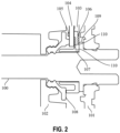
- the Fig. 2 shows a sectional view through the electrical contact element 100 according to a second embodiment.
- the hard component region 107 is made of a thermoplastic.
- the thermally conductive region 106 is made of ceramic.
- the ceramic together with the thermoplastic, exhibits structural mechanical properties, thus ensuring mechanical resilience and thermal conductivity.
- a thermally conductive paste 110 is applied between the pin 100 and the component carrier 103, as well as between the component carrier 103 and the circuit board 104.
- the thermally conductive paste 110 is applied between the component carrier 103 and the circuit board 104 or between the pin 100 and the component carrier 103.
- the Fig. 3 shows a sectional view through the electrical contact element 100 according to a third embodiment.
- the component carrier 103 is overmolded around the pin 100.
- the component carrier 103 is made of a plastic, in particular an elastomer.
- the elastomer is molded onto a projection 109 of the pin 100 in an area between the front housing element 102 and the rear housing element 101.
- the printed circuit board 104 lies directly against the component carrier 103 and is fastened to the component carrier 103, for example, via clip elements.
- the elastic sealing mat 108 comprises a nose 111 on the side facing the temperature sensor 105.
- the nose 111 lies against the surface of the printed circuit board 104 arranged on the temperature sensor 105 and protects the temperature sensor 105 from mechanical Stresses, particularly when joining the front housing element 102 to the rear housing element 101.
- the nose 111 can compensate for component tolerances.
- the nose 111 can also be elastic.
- pin 100 is fixed into rear housing element 101.
- pin 100 can be pressed into rear housing element 101.
- Thermally conductive paste 110 can be applied to component carrier 103.
- thermally conductive paste 110 can also be applied to contact element 100.
- the printed circuit board 104 is then attached to the surface of component carrier 103 coated with thermally conductive paste 110.
- the sealing mat 108 is arranged on front housing element 102. Front housing element 102 is pushed over pin 100, simultaneously pressing component carrier 103 with printed circuit board 104 against pin 100.
- the approach presented here features a cost-effective and simple architecture.
- Thermally coupling the temperature sensor with the contact element via the circuit board and the thermally conductive area of the component carrier simplifies temperature sensing and ensures increased measurement accuracy.
- the component carrier can be manufactured as a single injection-molded plastic part and molded directly onto the contact element.
- the assembly of the electrical coupling element can be automated using plug-in assembly.
Landscapes
- Engineering & Computer Science (AREA)
- Microelectronics & Electronic Packaging (AREA)
- Physics & Mathematics (AREA)
- General Physics & Mathematics (AREA)
- Power Engineering (AREA)
- Transportation (AREA)
- Mechanical Engineering (AREA)
- Measuring Temperature Or Quantity Of Heat (AREA)
Description
- Die vorliegende Erfindung betrifft eine Vorrichtung zum Erfassen einer Temperatur eines elektrischen Kopplungselements. Des Weiteren betrifft die Erfindung ein Verfahren zum Erfassen einer Temperatur eines elektrischen Kopplungselements.
- Während einem elektrischen Ladevorgang eines Elektrofahrzeugs entsteht durch die Stromund Spannungsübertragung Wärmeenergie innerhalb eines elektrischen Koppelungselement, wie beispielsweise eine Ladebuchse und ein Ladestecker. Durch die entstehende Wärmeenergie während des Stromflusses können die Ladebuchse und der Ladestecker überhitzen. Um einen sicheren Betrieb des elektrischen Ladevorgangs zu gewährleisten, wird die Temperatur der strom- und spannungführenden Elemente der Ladebuchse und des Ladesteckers gemessen. Dies kann über einen Temperatursensor erfolgen, welcher über Kabel mit den strom- und spannungsführenden Elementen verbunden ist. Dies erfordert einen hohen Montageaufwand und einen langen Wärmeleitungsweg. Die Temperatur kann auch über Temperatursensoren gemessen werden, welche auf einer Leiterplatte befestigt sind.
- Die
DE 10 2019 114 229 A1 bezieht sich auf einen Ladestecker insbesondere für ein Elektrofahrzeug, wobei der Ladestecker eine Schaltung auf einer Leiterplatte, einen Komponententräger und zumindest ein quer zu der Leiterplatte ausgerichtetes Kontaktelement aufweist, wobei die Schaltung für das Kontaktelement einen Temperatursensor aufweist und der Komponententräger aus einem elektrisch isolierenden, wärmeleitenden Material besteht, wobei der Temperatursensor auf einer quer zu dem Kontaktelement ausgerichteten Vorderseite der Leiterplatte in einem Randbereich der Leiterplatte angeordnet ist und der Komponententräger als elektrischer Isolator und Wärmeleiter zwischen dem Kontaktelement und dem Temperatursensor angeordnet ist, wobei der Komponententräger zumindest im Bereich des Temperatursensors an dem Kontaktelement anliegt und der Temperatursensor in einer Vertiefung des Komponententrägers angeordnet ist. - Die
DE 10 2016 401 A1 offenbart einen Steckvorrichtungseinsatz, welcher Kontaktelemente wie beispielsweise Kontaktstifte zur Leitung des elektrischen Stromes enthält. Die Kontaktelemente enthalten einen Kontaktbereich, in welchem sie komplementäre Kontaktelemente berühren, und einen Anschlussbereich, in welchem ein Leiter angeschlossen ist. Die Temperatur mindestens eines Kontaktelementes wird in einem Messbereich erfasst, der zwischen dem Kontaktbereich und dem Anschlussbereich liegt. - Die
WO 2018/197247 A1 offenbart ein Steckverbinderteil zum Verbinden mit einem Gegensteckverbinderteil mit einem Gehäuseteil, einem am Gehäuseteil angeordneten elektrischen Kontaktelement zur Herstellung einer elektrische Kontaktierung mit dem Gegensteckverbinderteil und eine Temperaturüberwachungseinrichtung mit einer Sensoreinrichtung (56) zur Erkennung einer Erwärmung des Kontaktelements. - Eine Aufgabe der Erfindung ist es daher, unter Einsatz konstruktiv möglichst einfacher Mittel eine effiziente Temperaturmessung von elektrischen strom- und spannungsführenden Komponenten während einem elektrischen Ladevorgang durchzuführen.
- Die Aufgabe wird durch die Gegenstände der unabhängigen Ansprüche gelöst. Vorteilhafte Weiterbildungen der Erfindung sind in den abhängigen Ansprüchen, der Beschreibung und den begleitenden Figuren angegeben.
- Ein Aspekt der Erfindung betrifft eine Vorrichtung zum Erfassen einer Temperatur eines elektrischen Kopplungselements umfassend ein elektrisches Kontaktelement, das eingerichtet ist, elektrischen Strom zu einer elektrischen Komponente zu führen und einen Komponententräger, welcher an dem Kontaktelement angeordnet ist und der Komponententräger einen thermisch leitfähigen Bereich im unmittelbaren Kontakt mit dem Kontaktelement umfasst, wobei an dem Komponententräger eine Leiterplatte angeordnet ist, welche wenigstens einen Temperatursensor umfasst, der die Temperatur des Kontaktelements und damit des elektrischen Kopplungselements erfasst.
- Das elektrische Kopplungselement kann eine Ladebuchse oder ein Ladestecker sein, welche für einen elektrischen Ladevorgang, insbesondere bei einem Elektrofahrzeug, benötigt werden. Um das Elektrofahrzeug elektrisch zu laden, wird das elektrische Kopplungselement, zum Beispiel der Ladebuchse, mit einem weiteren elektrischen Kopplungselement, zum Beispiel dem Ladestecker, gekoppelt. Das Kontaktelement ist zum Beispiel ein Hochvolt-Pin, welcher sich innerhalb des elektrischen Kopplungselement befindet. Das Kontaktelement kann insbesondere aus einem Metallmaterial bestehen. Das elektrische Kopplungselement kann mehrere Kontaktelemente aufweisen. Während einem elektrischen Laden fließen in dem Kontaktelement hohe elektrische Spannungen und Ladeströme.
- Der Komponententräger ist an dem Kontaktelement angeordnet und umfasst im unmittelbaren Kontakt mit dem Kontaktelement einen thermisch leitfähigen Bereich. Der Komponententräger umfasst vorzugsweise eine Hartkomponente, beispielsweise ein Thermoplast, und den thermisch leitfähigen Bereich als Weichkomponente. Der thermisch leitfähige Bereich als Weichkomponente dient dem gerichteten Wärmetransport vom Kontaktelement zum Temperatursensor. Die Hartkomponente wird benötigt, um eine Montage mit hohem Automatisierungsgrad zu erleichtern. Zudem ist die Geometrie der Hartkomponente derart ausgeformt, dass die erforderlichen Mindestwerte für die Luft- und Kriechstrecken zwischen dem Kontaktelement und dem Temperatursensor übertroffen werden. Die Hartkomponente hat eine sehr geringe thermische Leitfähigkeit (z.B. 0,15 W/(m*K), sodass der Wärmestrom an die umgebende Luft und die angrenzenden Bauteile minimiert wird. Der Komponententräger kann mit dem Kontaktelement verschraubt werden. Der thermisch leitfähige Bereich dient zur galvanischen Trennung zwischen dem Kontaktelement und dem Temperatursensor. Der Wärmestrom des Kontaktelements wird über den thermisch leitfähigen Bereich zu dem Temperatursensor geleitet. Zum Beispiel kann ein Elastomer als der thermisch leitfähige Bereich ausgestaltet sein. Ebenso kann der thermisch leitfähige Bereich keramische oder mineralische Elemente aufweisen, welche eine höhere Wärmeleitfähigkeit des thermisch leitfähigen Bereichs erweisen. Zum Beispiel kann der thermisch leitfähige Bereich eine Wärmeleitfähigkeit von 1,5 W/(m*K) erreichen. Dabei ist jedoch zu beachten, dass ein zu hoher Füllgrad dazu führen kann, dass der Elastomer hart wird und sich weniger gut dem Kontaktelement und der Leiterplatte anschmiegt. Es muss also ein Kompromiss aus Wärmeleitfähigkeit und Härte für den thermisch leitfähigen Bereich getroffen werden.
- Der Komponententräger kann einen weiteren Bereich umfassen, welcher aus einer Hartkomponente, beispielsweise einem Thermoplast, besteht. Dieser Bereich ist mechanisch beanspruchbar und dient der erleichterten Montage des Komponententrägers auf dem Kontaktelement. Je nach Fertigungs- und Montageverfahren können die mechanischen Anforderungen des Komponententrägers variieren. Zusätzlich erreicht der weitere Bereich nur eine geringe Wärmeleitfähigkeit, wodurch der Wärmestrom über den thermisch leitfähigen Bereich zu dem Temperatursensor leitet. Der Komponententräger ist so ausgeformt, dass er die Luft- und Kriechstrecken für die Hochvolt-Niedervolt-Trennung gewährleistet. Dafür ist ein Kragen vorgesehen, welcher parallel zur Oberfläche des Kontaktelements verläuft und diesen gegen die Leiterplatte elektrisch isoliert. Der Temperatursensor ist auf der dem Komponententräger abgewandten Seite der Leiterplatte platziert, um ihn vor mechanischer Beanspruchung zu schützen
- Der Komponententräger kann auf einer Schulter des Kontaktelements anliegen. Die Schulter kann ein Vorsprung des Kontaktelements sein. Die Schulter kann ringförmig um das Kontaktelement umlaufen.
- An dem Komponententräger ist die Leiterplatte angeordnet. Die Leiterplatte kann über Clipselemente an dem Komponententräger befestigt werden. Die Leiterplatte kann als PCB bezeichnet werden. An der Leiterplatte ist der Temperatursensor angeordnet, welcher möglichst unmittelbar zum thermisch leitfähigen Bereich und zum Kontaktelement angeordnet ist. Der Temperatursensor kann auf die Leiterplatte gelötet sein. Der Temperatursensor kann auf einem niedrigen Spannungsniveau, beispielsweise bis zu 12 Volt, betrieben werden. Durch die unmittelbare Anordnung des Temperatursensors an dem thermisch leitfähigen Bereich entsteht ein geringerer Wärmeverlust, welcher eine Genauigkeit der erfassten Werte des Temperatursensors gewährleistet.
- Der Temperatursensor kann einen Wert einer Temperatur des elektrischen Kopplungselements erfassen und in einem elektrischen Signal abbilden. Der Temperatursensor ist dem Kontaktelement elektrisch isoliert und ist außerhalb eines Hochvoltbereichs des Kontaktelements angeordnet.
- Die Vorrichtung kann ein Gehäuse umfassen, welches mehrteilig ausgebildet ist. Das Gehäuse kann aus einem elektrisch isolierenden Material bestehen. Das Gehäuse kann Aufnahmen für mehrere Kontaktelemente aufweisen. Das Kontaktelement kann in einem hinteren Gehäuseelement eingepresst werden. Zwischen dem hinteren Gehäuseelement und einem vorderen Gehäuseelement können der Komponententräger, die Leiterplatte und der Temperatursensor angeordnet sein, welche bei einem Zusammenbau des Gehäuses innerhalb des Gehäuses eingeschlossen werden. Das Gehäuses kann beispielsweise zusammengesteckt werden.
- Eine elastische Dichtungsmatte kann zwischen einem vorderen Gehäuseelement und der Leiterplatte angeordnet sein. Die Dichtungsmatte kann im Bereich des Temperatursensors eine Nase aufweisen. Die Nase kann als Anschlagfläche für die Leiterplatte dienen.
- Die Nase kann ebenfalls elastisch sein. Die Nase kann Bauteiltoleranzen ausgleichen. Das Kontaktelement kann in einem hinteren Gehäuseelement fixiert sein. Zum Beispiel kann das Kontaktelement in das hintere Gehäuseelement eingepresst werden. Das vordere Gehäuseelement und das hintere Gehäuseelement können miteinander verbunden werden, um den Komponententräger mit der Leiterplatte in einem Innenraum des Gehäuses einzuschließen.
- Weiterhin ist die Leiterplatte unmittelbar an dem thermisch leitfähigen Bereich angeordnet. Um den Temperatursensor vor mechanischer Beanspruchung zu schützen, ist der Temperatursensor auf der dem thermisch leitfähigen Bereich abgewandten Seite der Leiterplatte angeordnet.
- Ferner ist eine Wärmleitpaste zur Erhöhung der Wärmeleitfähigkeit zwischen Kontaktelement und Komponententräger und/oder zwischen Komponententräger und Leiterplatte einbringbar. Der Temperatursensor kann unter Verwendung des Wärmeleitmaterials thermisch mit der Leiterplatte und dem Komponententräger gekoppelt sein. Durch eine erhöhte Wärmeleitfähigkeit wird eine Genauigkeit der erfassten der Temperaturwerte gewährleistet.
- In einer bevorzugten Ausführungsform umfasst die Leiterplatte wärmeleitende Elemente zur Erhöhung der Wärmeleitfähigkeit der Leiterplatte. Dabei können zum Beispiel in die Leiterplatte Kupferelemente als wärmeleitende Elemente in die Leiterplatte eingebettet sein. Hierfür sind gerade im Bereich des Temperatursensors Elemente mit hoher Wärmeleitfähigkeit in die Leiterplatte eingebettet, beispielsweise thermische Vias aus Kupfer. Die Leiterplatte kann die wärmeleitenden Elemente unmittelbar an dem Temperatursensor umfassen.
- Weiterhin ist vorgesehen, dass an dem Komponententräger mindestens eine weitere Leiterplatte angeordnet ist, welche wenigstens einen weiteren Temperatursensor umfasst. Durch weitere Leiterplatten und Temperatursensoren kann die Temperatur des Kontaktelements an dem Kontaktelement an mehreren Messpunkten erfasst werden. Durch die Erfassung der Temperatur an mehreren Messpunkten des Kontaktelements können Temperaturabweichungen des Kontaktelements berücksichtigt werden. Zur Erfassung der Gesamttemperatur kann eine Mittelung der erfassten Werte erfolgen.
- Die Erfindung betrifft weiterhin ein Verfahren zum Erfassen einer Temperatur eines elektrischen Kopplungselements, umfassend ein Bereitstellen eines elektrischen Kontaktelements, das eingerichtet ist, elektrischen Strom zu einer elektrischen Komponente zu führen, ein Anordnen eines Komponententrägers an dem Kontaktelement, wobei der Komponententräger einen thermisch leitfähigen Bereich im unmittelbaren Kontakt mit dem Kontaktelement umfasst und ein Anordnen der Leiterplatte an dem Komponententräger, welche wenigstens einen Temperatursensor umfasst, wobei durch den Temperatursensor die Temperatur des elektrischen Kopplungselements erfasst wird.
- Die Temperatur wird auf der dem thermisch leitfähigen Bereich abgewandten Seite der Leiterplatte gemessen.
- Ferner wird eine Wärmleitpaste zur Erhöhung der Wärmeleitfähigkeit zwischen Kontaktelement und Komponententräger und/oder zwischen Komponententräger und Leiterplatte eingebracht. Die Wärmeleitpaste kann elastisch, beziehungsweise plastisch verformbar sein.
- In einer weiteren Ausführungsform umfasst das Anordnen des Komponententrägers an dem Kontaktelement ein Anspritzen mit einem Kunststoff an das Kontaktelement. Der Komponententräger kann somit als Spritzgussteil direkt an das Kontaktelement angespritzt werden. Dies ermöglicht einen hohen Automatisierungsgrad bei einem Zusammenbau des elektrischen Kopplungselements.
- Weiterhin wird an dem Komponententräger mindestens eine weitere Leiterplatte angeordnet, welche wenigstens einen weiteren Temperatursensor umfasst.
- Nachfolgend wird ein vorteilhaftes Ausführungsbeispiel der Erfindung unter Bezugnahme auf die begleitenden Figuren erläutert. Es zeigen:
- Figur 1
- eine Schnittdarstellung durch das elektrische Kontaktelement gemäß einem ersten Ausführungsbeispiel,
- Figur 2
- eine Schnittdarstellung durch das elektrische Kontaktelement gemäß einem zweiten Ausführungsbeispiel und
- Figur 3
- eine Schnittdarstellung durch das elektrische Kontaktelement gemäß einem dritten Ausführungsbeispiel.
- Die Figuren sind lediglich schematische Darstellungen und dienen nur der Erläuterung der Erfindung. Gleiche oder gleichwirkende Elemente sind durchgängig mit den gleichen Bezugszeichen versehen.
- Die
Fig. 1 zeigt eine Schnittdarstellung durch das elektrische Kontaktelement 100 gemäß einem ersten Ausführungsbeispiel. - Das elektrische Kontaktelement 100 ist Teil eines elektrischen Kopplungselements. Beispielsweise kann das elektrische Kopplungselement ein Ladestecker oder eine Ladebuchse, insbesondere für ein Elektrofahrzeug sein. In dem ersten Ausführungsbeispiel ist das elektrische Kontaktelement 100 ein Pin 100. Der Pin 100 ist in einem hinteren Gehäuseelement 101 eines zweiteiligen Gehäuses eingesetzt und mechanisch mit dem hinteren Gehäuseelement 101 verbunden. Das hintere Gehäuseelement 101 kann mit einem vorderen Gehäuseelement 102 beispielsweise über Verschrauben, Clipsen oder Verschweißen miteinander verbunden werden. Zwischen dem hinteren Gehäuseelement 101 und einem vorderen Gehäuseelement 102 sind ein Komponententräger 103 und eine Leiterplatte 104 angeordnet.
- Die Leiterplatte 104 liegt an dem Komponententräger 103 an und ist an dem Komponententräger 103 befestigt. Die Leiterplatte 104 umfasst an einer des Komponententrägers 103 gegenüberliegenden Seite der Leiterplatte 104 einen Temperatursensor 105. Der Temperatursensor 105 dient zur Erfassung der Temperatur der elektronischen Komponente, insbesondere des Pins 100.
- Weiterhin umfasst der Komponententräger 103 einen thermisch leitfähigen Bereich 106. Der Temperatursensor 105 ist so nahe wie möglich an einer Kontaktstelle zwischen dem Pin 100 und dem thermisch leitfähigen Bereich 106 angeordnet. Der thermisch leitfähige Bereich 106 kann aus einem thermisch leitfähigen Elastomer bestehen. Ein Wärmestrom des Pins 100 leitet somit über den thermisch leitfähigen Bereich 106 des Komponententrägers 103 über die Leiterplatte 104 zu dem Temperatursensor 105. Zur Erhöhung der Wärmeleitfähigkeit der Leiterplatte 104, kann die Leiterplatte 104 in einem Bereich des Temperatursensors 105 wärmeleitende Elemente aufweisen.
- Der Komponententräger 103 isoliert den Temperatursensor 105 von der im Betrieb an dem Pin 100 anliegenden Hochvoltspannung. Der Komponententräger 103 umfasst neben dem thermisch leitfähigen Bereich 106 einen Hartkomponentenbereich 107, welcher eine geringe Wärmeleitfähigkeit aufweist. Der Hartkomponentenbereich 107 kann zum Beispiel eine Wärmeleitfähigkeit von 0,15 W/(m*K) aufweisen. Zusätzlich ist der Hartkomponentenbereich 107 mechanisch beanspruchbar.
- Der Komponententräger 103 ist auf einem Vorsprung 109 des Kontaktelements 100 so anzuordnen, dass der thermisch leitfähige Bereich 106 direkt auf dem Vorsprung 109 des Kontaktelements 100 anliegt. Dadurch leitet der Wärmestrom direkt von dem Kontaktelement 100 über den thermisch leitfähigen Bereich 106 zu dem Temperatursensor 105.
- An dem Pin 100 ist eine elastische Dichtungsmatte 108 angeordnet, welche den Pin 100 zum Beispiel fluiddicht abdichtet. Die Dichtungsmatte 108 ist in dem vorderen Gehäuseelement 102 eingesetzt.
- Die
Fig. 2 zeigt eine Schnittdarstellung durch das elektrische Kontaktelement 100 gemäß einem zweiten Ausführungsbeispiel. - Gemäß dem zweiten Ausführungsbeispiel besteht der Hartkomponentenbereich 107 aus einem Thermoplast. Der thermisch leitfähige Bereich 106 besteht aus Keramik. Das Keramik weist mit dem Thermoplast strukturmechanische Eigenschaften auf, sodass die mechanische Beanspruchbarkeit und die thermische Leitfähigkeit gewährleistet wird. Zwischen dem Pin 100 und dem Komponententräger 103, sowie zwischen dem Komponententräger 103 und der Leiterplatte 104 ist eine Wärmeleitpaste 110 aufgetragen. Gemäß einem weiteren Ausführungsbeispiel ist die Wärmeleitpaste 110 zwischen dem Komponententräger 103 und der Leiterplatte 104 oder zwischen dem Pin 100 und dem Komponententräger 103 aufgetragen.
- Die
Fig. 3 zeigt eine Schnittdarstellung durch das elektrische Kontaktelement 100 gemäß einem dritten Ausführungsbeispiel. - Gemäß dem dritten Ausführungsbeispiel ist der Komponententräger 103 um den Pin 100 umspritzt. Der Komponententräger 103 besteht dabei aus einem Kunststoff, insbesondere aus einem Elastomer. Das Elastomer wird in einem Bereich zwischen dem vorderen Gehäuseelement 102 und dem hinteren Gehäuseelement 101 an einem Vorsprung 109 des Pins 100 angespritzt. Die Leiterplatte 104 liegt direkt an dem Komponententräger 103 an und ist zum Beispiel über Clipselemente an dem Komponententräger 103 befestigt. Die elastische Dichtungsmatte 108 umfasst an der zum Temperatursensor 105 gewandten Seite eine Nase 111. Die Nase 111 liegt an der des Temperatursensors 105 angeordneten Fläche der Leiterplatte 104 an und schützt den Temperatursensor 105 vor mechanischen Beanspruchungen, insbesondere beim Zusammenfügen des vorderen Gehäuseelements 102 mit dem hinteren Gehäuseelement 101. Weiterhin kann die Nase 111 Bauteiltoleranzen ausgleichen. Die Nase 111 kann ebenfalls elastisch sein.
- Zur Montage wird der Pin 100 in das hintere Gehäuseelement 101 fixiert. Beispielsweise kann der Pin 100 in das hintere Gehäuseelement 101 eingepresst werden. Auf den Komponententräger 103 kann Wärmeleitpaste 110 aufgetragen werden. Alternativ kann die Wärmeleitpaste 110 auch auf das Kontaktelement 100 aufgetragen werden. Anschließend wird die Leiterplatte 104 an der mit Wärmeleitpaste 110 aufgetragenen Fläche des Komponententrägers 103 befestigt. An dem vorderen Gehäuseelement 102 wird die Dichtungsmatte 108 angeordnet. Das vordere Gehäuseelement 102 wird über den Pin 100 geschoben und damit gleichzeitig der Komponententräger 103 mit der Leiterplatte 104 gegen den Pin 100 gepresst.
- Der hier vorgestellte Ansatz weist eine kostengünstige und einfache Architektur auf. Durch die thermische Kopplung des Temperatursensors mit dem Kontaktelement über die Leiterplatte und den thermisch leitfähigen Bereich des Komponententrägers wird die Temperaturerfassung vereinfacht und es kann eine erhöhte Messgenauigkeit sichergestellt werden. Der Komponententräger kann als ein Spritzgussteil aus Kunststoff hergestellt werden und direkt an das Kontaktelement angespritzt werden. Der Zusammenbau des elektrischen Kopplungselement kann durch eine Steckmontage automatisiert erfolgen.
-
- 100
- Kontaktelement
- 101
- hinteres Gehäuseelement
- 102
- vorderes Gehäuseelement
- 103
- Komponententräger
- 104
- Leiterplatte
- 105
- Temperatursensor
- 106
- thermisch leitfähiger Bereich
- 107
- Hartkomponentenbereich
- 108
- Dichtungsmatte
- 109
- Vorsprung
- 110
- Wärmeleitpaste
- 111
- Nase
Claims (9)
- Vorrichtung zum Erfassen einer Temperatur eines elektrischen Kopplungselements umfassendein elektrisches Kontaktelement (100), das eingerichtet ist, elektrischen Strom zu einer elektrischen Komponente zu führen;einen Komponententräger (103), welcher an dem Kontaktelement (100) anordbar ist und der Komponententräger (103) einen thermisch leitfähigen Bereich (106) im unmittelbaren Kontakt mit dem Kontaktelement (100) umfasst, wobei an dem Komponententräger (103) eine Leiterplatte (104) angeordnet ist, welche wenigstens einen Temperatursensor (105) umfasst, der die Temperatur des Kontaktelements (100) und damit des elektrischen Kopplungselements erfasst, dadurch gekennzeichnet, dass die Leiterplatte (104) unmittelbar an dem thermisch leitfähigen Bereich (106) angeordnet ist und der Temperatursensor (105) auf der dem thermisch leitfähigen Bereich (106) abgewandten Seite der Leiterplatte (104) angeordnet ist.
- Vorrichtung nach Anspruch 1, dadurch gekennzeichnet, dass eine Wärmleitpaste (110) zur Erhöhung der Wärmeleitfähigkeit zwischen Kontaktelement (100) und Komponententräger (103) und/oder zwischen Komponententräger (103) und Leiterplatte (104) einbringbar ist.
- Vorrichtung nach einem der vorstehenden Ansprüche, wobei die Leiterplatte (104) wärmeleitende Elemente zur Erhöhung der Wärmeleitfähigkeit der Leiterplatte (104) umfasst.
- Vorrichtung nach einem der vorstehenden Ansprüche, dadurch gekennzeichnet, dass an dem Komponententräger (103) mindestens eine weitere Leiterplatte (104) angeordnet ist, welche wenigstens einen weiteren Temperatursensor (105) umfasst.
- Verfahren zum Erfassen einer Temperatur eines elektrischen Kopplungselements, umfassendBereitstellen eines elektrischen Kontaktelements (100), das eingerichtet ist, elektrischen Strom zu einer elektrischen Komponente zu führen,Anordnen eines Komponententrägers (103) an dem Kontaktelement (100), wobei der Komponententräger (103) einen thermisch leitfähigen Bereich (106) im unmittelbaren Kontakt mit dem Kontaktelement (100) umfasst, undAnordnen der Leiterplatte (104) an dem Komponententräger (103), welche wenigstens einen Temperatursensor (105) umfasst, dadurch gekennzeichnet, dass die Leiterplatte (104) unmittelbar an dem thermisch leitfähigen Bereich (106) angeordnet wird und der Temperatursensor (105) auf der dem thermisch leitfähigen Bereich (106) abgewandten Seite der Leiterplatte (104) angeordnet wird und wobei durch den Temperatursensor (105) die Temperatur des Kontaktelements (100) und damit des elektrischen Kopplungselements erfasst wird.
- Verfahren nach Anspruch 5, dadurch gekennzeichnet, dass die Temperatur auf der dem thermisch leitfähigen Bereich (106) abgewandten Seite der Leiterplatte (104) gemessen wird.
- Verfahren nach einem der Ansprüche 5 oder 6, dadurch gekennzeichnet, dass eine Wärmleitpaste (110) zur Erhöhung der Wärmeleitfähigkeit zwischen Kontaktelement (100) und Komponententräger (103) und/oder zwischen Komponententräger (103) und Leiterplatte (104) eingebracht wird.
- Verfahren nach einem der Ansprüche 5 bis 7, wobei das Anordnen des Komponententrägers (103) an dem Kontaktelement (100) ein Anspritzen mit einem Kunststoff an das Kontaktelement (100) umfasst.
- Verfahren nach einem der Ansprüche 5 bis 8, dadurch gekennzeichnet, dass an dem Komponententräger (103) mindestens eine weitere Leiterplatte (104) angeordnet wird, welche wenigstens einen weiteren Temperatursensor (105) umfasst.
Priority Applications (1)
| Application Number | Priority Date | Filing Date | Title |
|---|---|---|---|
| EP23196067.5A EP4282692A3 (de) | 2020-04-29 | 2021-04-28 | Vorrichtung zum erfassen einer temperatur eines elektrischen kopplungselements und verfahren |
Applications Claiming Priority (2)
| Application Number | Priority Date | Filing Date | Title |
|---|---|---|---|
| DE102020111641.1A DE102020111641B4 (de) | 2020-04-29 | 2020-04-29 | Vorrichtung zum erfassen einer temperatur eines elektrischen kopplungselements und verfahren |
| PCT/EP2021/061042 WO2021219676A1 (de) | 2020-04-29 | 2021-04-28 | Vorrichtung zum erfassen einer temperatur eines elektrischen kopplungselements und verfahren |
Related Child Applications (2)
| Application Number | Title | Priority Date | Filing Date |
|---|---|---|---|
| EP23196067.5A Division-Into EP4282692A3 (de) | 2020-04-29 | 2021-04-28 | Vorrichtung zum erfassen einer temperatur eines elektrischen kopplungselements und verfahren |
| EP23196067.5A Division EP4282692A3 (de) | 2020-04-29 | 2021-04-28 | Vorrichtung zum erfassen einer temperatur eines elektrischen kopplungselements und verfahren |
Publications (2)
| Publication Number | Publication Date |
|---|---|
| EP4143929A1 EP4143929A1 (de) | 2023-03-08 |
| EP4143929B1 true EP4143929B1 (de) | 2025-06-11 |
Family
ID=75746620
Family Applications (2)
| Application Number | Title | Priority Date | Filing Date |
|---|---|---|---|
| EP21722430.2A Active EP4143929B1 (de) | 2020-04-29 | 2021-04-28 | Vorrichtung zum erfassen einer temperatur eines elektrischen kopplungselements und verfahren |
| EP23196067.5A Pending EP4282692A3 (de) | 2020-04-29 | 2021-04-28 | Vorrichtung zum erfassen einer temperatur eines elektrischen kopplungselements und verfahren |
Family Applications After (1)
| Application Number | Title | Priority Date | Filing Date |
|---|---|---|---|
| EP23196067.5A Pending EP4282692A3 (de) | 2020-04-29 | 2021-04-28 | Vorrichtung zum erfassen einer temperatur eines elektrischen kopplungselements und verfahren |
Country Status (5)
| Country | Link |
|---|---|
| US (1) | US20240006824A1 (de) |
| EP (2) | EP4143929B1 (de) |
| CN (1) | CN115461941A (de) |
| DE (1) | DE102020111641B4 (de) |
| WO (1) | WO2021219676A1 (de) |
Family Cites Families (10)
| Publication number | Priority date | Publication date | Assignee | Title |
|---|---|---|---|---|
| DE102015106251A1 (de) | 2015-04-23 | 2016-10-27 | Phoenix Contact E-Mobility Gmbh | Steckverbinderteil mit einer Temperaturüberwachungseinrichtung |
| DE102016107401A1 (de) | 2016-02-26 | 2017-08-31 | Amad Mennekes Holding Gmbh & Co. Kg | Steckvorrichtung mit Temperaturerfassung |
| BE1025169B1 (de) | 2017-04-24 | 2018-11-28 | Phoenix Contact E-Mobility Gmbh | Steckverbinderteil mit einer Temperaturüberwachungseinrichtung |
| CN208171458U (zh) * | 2018-05-31 | 2018-11-30 | 泰科电子(上海)有限公司 | 温度传感器导热组件及连接器 |
| US10833458B2 (en) * | 2018-08-21 | 2020-11-10 | Te Connectivity Corporation | Temperature sensor assembly for an electrical connector |
| EP3644456B1 (de) | 2018-10-26 | 2021-07-21 | Aptiv Technologies Limited | Verbinderanordnung mit thermischer überwachung |
| DE102018131558A1 (de) | 2018-12-10 | 2020-06-10 | Phoenix Contact E-Mobility Gmbh | Steckverbinderteil mit einer Temperaturüberwachungseinrichtung |
| US11169081B2 (en) * | 2019-02-19 | 2021-11-09 | International Business Machines Corporation | Silicone-modified corrosion monitor |
| DE102019114229A1 (de) | 2019-05-28 | 2019-10-02 | Lisa Dräxlmaier GmbH | Ladestecker insbesondere für ein Elektrofahrzeug und Verfahren zum Herstellen desselben. |
| LU101309B1 (de) | 2019-07-11 | 2021-01-11 | Phoenix Contact E Mobility Gmbh | Elektrische Baugruppe mit einer Temperaturüberwachungseinrichtung |
-
2020
- 2020-04-29 DE DE102020111641.1A patent/DE102020111641B4/de active Active
-
2021
- 2021-04-28 US US17/922,389 patent/US20240006824A1/en active Pending
- 2021-04-28 EP EP21722430.2A patent/EP4143929B1/de active Active
- 2021-04-28 WO PCT/EP2021/061042 patent/WO2021219676A1/de not_active Ceased
- 2021-04-28 CN CN202180031151.1A patent/CN115461941A/zh active Pending
- 2021-04-28 EP EP23196067.5A patent/EP4282692A3/de active Pending
Also Published As
| Publication number | Publication date |
|---|---|
| EP4282692A2 (de) | 2023-11-29 |
| EP4282692A3 (de) | 2024-02-14 |
| WO2021219676A1 (de) | 2021-11-04 |
| EP4143929A1 (de) | 2023-03-08 |
| US20240006824A1 (en) | 2024-01-04 |
| DE102020111641A1 (de) | 2021-11-04 |
| DE102020111641B4 (de) | 2026-04-16 |
| CN115461941A (zh) | 2022-12-09 |
Similar Documents
| Publication | Publication Date | Title |
|---|---|---|
| EP3183781B1 (de) | Steckverbinderteil mit temperatursensoren | |
| EP3286804B1 (de) | Steckverbinderteil mit einer temperaturüberwachungseinrichtung | |
| EP4078120B1 (de) | Sensorvorrichtung, elektrische einrichtung mit sensorvorrichtung und fahrzeug mit sensorvorrichtung | |
| DE102013110548B4 (de) | Steckverbinderteil mit einer Widerstandkodierung | |
| EP2946220B1 (de) | Messanordnung mit einem messwiderstand | |
| WO2012069205A1 (de) | Elektrischer steckverbinder für thermoelemente und verfahren zu dessen herstellung | |
| DE102014102991B3 (de) | Steckverbinder mit Sensoranordnung | |
| EP2567429B1 (de) | Elektrischer baugruppenanschluss eines kraftfahrzeugs | |
| DE102018130835A1 (de) | Ladestecker mit einer Temperatursensoreinheit | |
| EP3463969B1 (de) | Stecker, insbesondere mit einem fahrzeugladekabel eines elektro- oder hybridfahrzeuges | |
| DE102020201240A1 (de) | Steckverbinderelement und Steckverbinder für Hochvoltanwendungen | |
| DE102018131558A1 (de) | Steckverbinderteil mit einer Temperaturüberwachungseinrichtung | |
| DE102009000828A1 (de) | Vorrichtung zur Befestigung eines Bolzens in einer Polklemme | |
| DE102012211749A1 (de) | Messwiderstand für Stromsensor und Stromsensoreinheit | |
| DE102019114229A1 (de) | Ladestecker insbesondere für ein Elektrofahrzeug und Verfahren zum Herstellen desselben. | |
| DE102021112703A1 (de) | Berührgeschützte Schraubverbindungseinrichtung | |
| DE102015104170B4 (de) | Anschlusssteckvorrichtung | |
| DE102019109393B4 (de) | Leiterplattendurchführung und elektrisch leitender pin zum führen in einer leiterplattendurchführung | |
| DE102019113607B4 (de) | Ladestecker für ein elektrofahrzeug | |
| EP2828672B1 (de) | Elektronischer batteriesensor | |
| DE102020111641B4 (de) | Vorrichtung zum erfassen einer temperatur eines elektrischen kopplungselements und verfahren | |
| EP4281737B1 (de) | Anordnung mit einem stiftförmigen elektrischen kontaktelement und einer temperaturmessvorrichtung zum messen einer temperatur des stiftförmigen elektrischen kontaktelements | |
| EP1643804A1 (de) | Lufterhitzer | |
| EP3734298B1 (de) | Messanordnung zum erfassen eines elektrischen stroms | |
| DE102021110681B3 (de) | Steckverbindung für Airbag-Zündsysteme |
Legal Events
| Date | Code | Title | Description |
|---|---|---|---|
| STAA | Information on the status of an ep patent application or granted ep patent |
Free format text: STATUS: UNKNOWN |
|
| STAA | Information on the status of an ep patent application or granted ep patent |
Free format text: STATUS: THE INTERNATIONAL PUBLICATION HAS BEEN MADE |
|
| PUAI | Public reference made under article 153(3) epc to a published international application that has entered the european phase |
Free format text: ORIGINAL CODE: 0009012 |
|
| STAA | Information on the status of an ep patent application or granted ep patent |
Free format text: STATUS: REQUEST FOR EXAMINATION WAS MADE |
|
| 17P | Request for examination filed |
Effective date: 20221017 |
|
| AK | Designated contracting states |
Kind code of ref document: A1 Designated state(s): AL AT BE BG CH CY CZ DE DK EE ES FI FR GB GR HR HU IE IS IT LI LT LU LV MC MK MT NL NO PL PT RO RS SE SI SK SM TR |
|
| DAV | Request for validation of the european patent (deleted) | ||
| DAX | Request for extension of the european patent (deleted) | ||
| GRAP | Despatch of communication of intention to grant a patent |
Free format text: ORIGINAL CODE: EPIDOSNIGR1 |
|
| STAA | Information on the status of an ep patent application or granted ep patent |
Free format text: STATUS: GRANT OF PATENT IS INTENDED |
|
| INTG | Intention to grant announced |
Effective date: 20241223 |
|
| GRAS | Grant fee paid |
Free format text: ORIGINAL CODE: EPIDOSNIGR3 |
|
| GRAA | (expected) grant |
Free format text: ORIGINAL CODE: 0009210 |
|
| STAA | Information on the status of an ep patent application or granted ep patent |
Free format text: STATUS: THE PATENT HAS BEEN GRANTED |
|
| AK | Designated contracting states |
Kind code of ref document: B1 Designated state(s): AL AT BE BG CH CY CZ DE DK EE ES FI FR GB GR HR HU IE IS IT LI LT LU LV MC MK MT NL NO PL PT RO RS SE SI SK SM TR |
|
| REG | Reference to a national code |
Ref country code: GB Ref legal event code: FG4D Free format text: NOT ENGLISH |
|
| REG | Reference to a national code |
Ref country code: CH Ref legal event code: EP |
|
| REG | Reference to a national code |
Ref country code: IE Ref legal event code: FG4D Free format text: LANGUAGE OF EP DOCUMENT: GERMAN |
|
| REG | Reference to a national code |
Ref country code: DE Ref legal event code: R096 Ref document number: 502021007716 Country of ref document: DE |
|
| PG25 | Lapsed in a contracting state [announced via postgrant information from national office to epo] |
Ref country code: ES Free format text: LAPSE BECAUSE OF FAILURE TO SUBMIT A TRANSLATION OF THE DESCRIPTION OR TO PAY THE FEE WITHIN THE PRESCRIBED TIME-LIMIT Effective date: 20250611 Ref country code: FI Free format text: LAPSE BECAUSE OF FAILURE TO SUBMIT A TRANSLATION OF THE DESCRIPTION OR TO PAY THE FEE WITHIN THE PRESCRIBED TIME-LIMIT Effective date: 20250611 |
|
| REG | Reference to a national code |
Ref country code: LT Ref legal event code: MG9D |
|
| PG25 | Lapsed in a contracting state [announced via postgrant information from national office to epo] |
Ref country code: GR Free format text: LAPSE BECAUSE OF FAILURE TO SUBMIT A TRANSLATION OF THE DESCRIPTION OR TO PAY THE FEE WITHIN THE PRESCRIBED TIME-LIMIT Effective date: 20250912 Ref country code: NO Free format text: LAPSE BECAUSE OF FAILURE TO SUBMIT A TRANSLATION OF THE DESCRIPTION OR TO PAY THE FEE WITHIN THE PRESCRIBED TIME-LIMIT Effective date: 20250911 |
|
| REG | Reference to a national code |
Ref country code: NL Ref legal event code: MP Effective date: 20250611 |
|
| PG25 | Lapsed in a contracting state [announced via postgrant information from national office to epo] |
Ref country code: BG Free format text: LAPSE BECAUSE OF FAILURE TO SUBMIT A TRANSLATION OF THE DESCRIPTION OR TO PAY THE FEE WITHIN THE PRESCRIBED TIME-LIMIT Effective date: 20250611 |
|
| PG25 | Lapsed in a contracting state [announced via postgrant information from national office to epo] |
Ref country code: HR Free format text: LAPSE BECAUSE OF FAILURE TO SUBMIT A TRANSLATION OF THE DESCRIPTION OR TO PAY THE FEE WITHIN THE PRESCRIBED TIME-LIMIT Effective date: 20250611 |
|
| PG25 | Lapsed in a contracting state [announced via postgrant information from national office to epo] |
Ref country code: RS Free format text: LAPSE BECAUSE OF FAILURE TO SUBMIT A TRANSLATION OF THE DESCRIPTION OR TO PAY THE FEE WITHIN THE PRESCRIBED TIME-LIMIT Effective date: 20250911 |
|
| PG25 | Lapsed in a contracting state [announced via postgrant information from national office to epo] |
Ref country code: LV Free format text: LAPSE BECAUSE OF FAILURE TO SUBMIT A TRANSLATION OF THE DESCRIPTION OR TO PAY THE FEE WITHIN THE PRESCRIBED TIME-LIMIT Effective date: 20250611 |
|
| PG25 | Lapsed in a contracting state [announced via postgrant information from national office to epo] |
Ref country code: NL Free format text: LAPSE BECAUSE OF FAILURE TO SUBMIT A TRANSLATION OF THE DESCRIPTION OR TO PAY THE FEE WITHIN THE PRESCRIBED TIME-LIMIT Effective date: 20250611 |
|
| PG25 | Lapsed in a contracting state [announced via postgrant information from national office to epo] |
Ref country code: PT Free format text: LAPSE BECAUSE OF FAILURE TO SUBMIT A TRANSLATION OF THE DESCRIPTION OR TO PAY THE FEE WITHIN THE PRESCRIBED TIME-LIMIT Effective date: 20251013 |
|
| PG25 | Lapsed in a contracting state [announced via postgrant information from national office to epo] |
Ref country code: IS Free format text: LAPSE BECAUSE OF FAILURE TO SUBMIT A TRANSLATION OF THE DESCRIPTION OR TO PAY THE FEE WITHIN THE PRESCRIBED TIME-LIMIT Effective date: 20251011 |
|
| PG25 | Lapsed in a contracting state [announced via postgrant information from national office to epo] |
Ref country code: SM Free format text: LAPSE BECAUSE OF FAILURE TO SUBMIT A TRANSLATION OF THE DESCRIPTION OR TO PAY THE FEE WITHIN THE PRESCRIBED TIME-LIMIT Effective date: 20250611 |
|
| PG25 | Lapsed in a contracting state [announced via postgrant information from national office to epo] |
Ref country code: CZ Free format text: LAPSE BECAUSE OF FAILURE TO SUBMIT A TRANSLATION OF THE DESCRIPTION OR TO PAY THE FEE WITHIN THE PRESCRIBED TIME-LIMIT Effective date: 20250611 |
|
| PG25 | Lapsed in a contracting state [announced via postgrant information from national office to epo] |
Ref country code: PL Free format text: LAPSE BECAUSE OF FAILURE TO SUBMIT A TRANSLATION OF THE DESCRIPTION OR TO PAY THE FEE WITHIN THE PRESCRIBED TIME-LIMIT Effective date: 20250611 |
|
| PG25 | Lapsed in a contracting state [announced via postgrant information from national office to epo] |
Ref country code: EE Free format text: LAPSE BECAUSE OF FAILURE TO SUBMIT A TRANSLATION OF THE DESCRIPTION OR TO PAY THE FEE WITHIN THE PRESCRIBED TIME-LIMIT Effective date: 20250611 |
|
| PG25 | Lapsed in a contracting state [announced via postgrant information from national office to epo] |
Ref country code: SK Free format text: LAPSE BECAUSE OF FAILURE TO SUBMIT A TRANSLATION OF THE DESCRIPTION OR TO PAY THE FEE WITHIN THE PRESCRIBED TIME-LIMIT Effective date: 20250611 |
|
| REG | Reference to a national code |
Ref country code: DE Ref legal event code: R097 Ref document number: 502021007716 Country of ref document: DE |
|
| PG25 | Lapsed in a contracting state [announced via postgrant information from national office to epo] |
Ref country code: DK Free format text: LAPSE BECAUSE OF FAILURE TO SUBMIT A TRANSLATION OF THE DESCRIPTION OR TO PAY THE FEE WITHIN THE PRESCRIBED TIME-LIMIT Effective date: 20250611 |
|
| PG25 | Lapsed in a contracting state [announced via postgrant information from national office to epo] |
Ref country code: IT Free format text: LAPSE BECAUSE OF FAILURE TO SUBMIT A TRANSLATION OF THE DESCRIPTION OR TO PAY THE FEE WITHIN THE PRESCRIBED TIME-LIMIT Effective date: 20250611 |
|
| PLBE | No opposition filed within time limit |
Free format text: ORIGINAL CODE: 0009261 |
|
| STAA | Information on the status of an ep patent application or granted ep patent |
Free format text: STATUS: NO OPPOSITION FILED WITHIN TIME LIMIT |
|
| REG | Reference to a national code |
Ref country code: CH Ref legal event code: L10 Free format text: ST27 STATUS EVENT CODE: U-0-0-L10-L00 (AS PROVIDED BY THE NATIONAL OFFICE) Effective date: 20260423 |