EP4142906B1 - Filter device and method for assembling and disassembling such a filter device - Google Patents
Filter device and method for assembling and disassembling such a filter device Download PDFInfo
- Publication number
- EP4142906B1 EP4142906B1 EP21712580.6A EP21712580A EP4142906B1 EP 4142906 B1 EP4142906 B1 EP 4142906B1 EP 21712580 A EP21712580 A EP 21712580A EP 4142906 B1 EP4142906 B1 EP 4142906B1
- Authority
- EP
- European Patent Office
- Prior art keywords
- housing
- vessel
- base surface
- filter element
- mating side
- Prior art date
- Legal status (The legal status is an assumption and is not a legal conclusion. Google has not performed a legal analysis and makes no representation as to the accuracy of the status listed.)
- Active
Links
Images




Classifications
-
- B—PERFORMING OPERATIONS; TRANSPORTING
- B01—PHYSICAL OR CHEMICAL PROCESSES OR APPARATUS IN GENERAL
- B01D—SEPARATION
- B01D29/00—Filters with filtering elements stationary during filtration, e.g. pressure or suction filters, not covered by groups B01D24/00 - B01D27/00; Filtering elements therefor
- B01D29/50—Filters with filtering elements stationary during filtration, e.g. pressure or suction filters, not covered by groups B01D24/00 - B01D27/00; Filtering elements therefor with multiple filtering elements, characterised by their mutual disposition
-
- B—PERFORMING OPERATIONS; TRANSPORTING
- B01—PHYSICAL OR CHEMICAL PROCESSES OR APPARATUS IN GENERAL
- B01D—SEPARATION
- B01D17/00—Separation of liquids, not provided for elsewhere, e.g. by thermal diffusion
- B01D17/02—Separation of non-miscible liquids
- B01D17/0208—Separation of non-miscible liquids by sedimentation
- B01D17/0214—Separation of non-miscible liquids by sedimentation with removal of one of the phases
-
- B—PERFORMING OPERATIONS; TRANSPORTING
- B01—PHYSICAL OR CHEMICAL PROCESSES OR APPARATUS IN GENERAL
- B01D—SEPARATION
- B01D17/00—Separation of liquids, not provided for elsewhere, e.g. by thermal diffusion
- B01D17/02—Separation of non-miscible liquids
- B01D17/04—Breaking emulsions
- B01D17/045—Breaking emulsions with coalescers
-
- B—PERFORMING OPERATIONS; TRANSPORTING
- B01—PHYSICAL OR CHEMICAL PROCESSES OR APPARATUS IN GENERAL
- B01D—SEPARATION
- B01D17/00—Separation of liquids, not provided for elsewhere, e.g. by thermal diffusion
-
- B—PERFORMING OPERATIONS; TRANSPORTING
- B01—PHYSICAL OR CHEMICAL PROCESSES OR APPARATUS IN GENERAL
- B01D—SEPARATION
- B01D17/00—Separation of liquids, not provided for elsewhere, e.g. by thermal diffusion
- B01D17/02—Separation of non-miscible liquids
- B01D17/0202—Separation of non-miscible liquids by ab- or adsorption
-
- B—PERFORMING OPERATIONS; TRANSPORTING
- B01—PHYSICAL OR CHEMICAL PROCESSES OR APPARATUS IN GENERAL
- B01D—SEPARATION
- B01D17/00—Separation of liquids, not provided for elsewhere, e.g. by thermal diffusion
- B01D17/08—Thickening liquid suspensions by filtration
- B01D17/10—Thickening liquid suspensions by filtration with stationary filtering elements
-
- B—PERFORMING OPERATIONS; TRANSPORTING
- B01—PHYSICAL OR CHEMICAL PROCESSES OR APPARATUS IN GENERAL
- B01D—SEPARATION
- B01D29/00—Filters with filtering elements stationary during filtration, e.g. pressure or suction filters, not covered by groups B01D24/00 - B01D27/00; Filtering elements therefor
- B01D29/60—Filters with filtering elements stationary during filtration, e.g. pressure or suction filters, not covered by groups B01D24/00 - B01D27/00; Filtering elements therefor integrally combined with devices for controlling the filtration
-
- B—PERFORMING OPERATIONS; TRANSPORTING
- B01—PHYSICAL OR CHEMICAL PROCESSES OR APPARATUS IN GENERAL
- B01D—SEPARATION
- B01D35/00—Filtering devices having features not specifically covered by groups B01D24/00 - B01D33/00, or for applications not specifically covered by groups B01D24/00 - B01D33/00; Auxiliary devices for filtration; Filter housing constructions
- B01D35/30—Filter housing constructions
-
- B—PERFORMING OPERATIONS; TRANSPORTING
- B01—PHYSICAL OR CHEMICAL PROCESSES OR APPARATUS IN GENERAL
- B01D—SEPARATION
- B01D36/00—Filter circuits or combinations of filters with other separating devices
-
- B—PERFORMING OPERATIONS; TRANSPORTING
- B01—PHYSICAL OR CHEMICAL PROCESSES OR APPARATUS IN GENERAL
- B01D—SEPARATION
- B01D36/00—Filter circuits or combinations of filters with other separating devices
- B01D36/02—Combinations of filters of different kinds
Definitions
- the present invention concerns a filter device for separating a liquid mixture and a method for assembling and disassembling such a filter device.
- the invention concerns a filter device for separating a liquid mixture
- a filter device for separating a liquid mixture
- a vessel configured to contain a first filter element and a housing configured to contain a second filter element
- the vessel and the housing comprise connection means to make a fluid connection between an outlet of the first filter element and an inlet of the second filter element, whereby the vessel and the housing are assembled as a compact entity while making this fluid connection, and whereby the filter device can be easily disassembled again into the vessel and the housing.
- a commonly known kind of filter devices is designed as a set of vertical cylindrical columns or 'towers', as for example described in EP 0003859 A1 , GB 2350571 A and EP 1502636 A1 .
- liquid to be separated is first sent through one of the vertical columns which contains a first filter element enabling a course separation of a bulk of liquid contaminants.
- the liquid is then further sent through the other columns which contain further filter elements enabling a finer separation.
- filter devices have been developed in which several components of the filter device have been integrated in a more compact and elegant design.
- GB 2251812 A and GB 2260133 A both describe an apparatus for separating oil from an oil-water mixture with a first separation chamber optionally containing a coalescence filter element and a second separation chamber containing a sorbent bed filter element.
- the first separation chamber is comprised in a vessel, while the second separation chamber is comprised in a housing separate from this vessel.
- the vessel has a re-entrant section in which the housing can be accommodated and where the vessel and the housing can be fluidly connected by inserting the housing in the re-entrant section and disconnected by removing the housing from the re-entrant section.
- the re-entrant section in the vessel is, however, positioned at an elevated level in the vessel, which involves a risk that the housing may accidently fall down to the ground upon removal from the re-entrant section, for example when replacement of the filter element in the housing is required, in particular when the housing is large and heavy. This complicates the removal of the housing from the re-entrant section, and may result in breakage of the housing and/or manual handling injuries.
- the purpose of the present invention is to provide a solution to one or more of the aforementioned and/or other disadvantages.
- the purpose of the present invention is to provide a filter device for separating liquid mixtures with a compact design and a high serviceability, even for large-scale filter devices dealing with large liquid mixture flows.
- the present invention concerns a filter device for separating a liquid mixture
- a 'horizontal flat ground surface' means a flat ground surface perpendicular to a direction in which a principal force of gravity, typically the gravitational attraction force of the earth, is exerted on the filter device.
- a 'horizontal flat ground surface' means a flat ground surface that is level oriented.
- 'stably stand' means that the filter device will not make a wobbling or tilting motion under the influence of a principal force of gravity exerted on the filter device, typically the gravitational attraction force of the earth, after the filter device has been exposed to a force with a horizontal component.
- a 'mantle surface' is a surface extending from a complete periphery of a base surface.
- a 'direction opposite to the vessel base surface' or a 'direction opposite to the housing base surface' is a direction opposite to a normal of the vessel base surface or the housing base surface, respectively.
- the advantage of such a filter device according to the invention is that when the vessel base surface is parallel to and level with the horizontal flat ground surface, as it should be the case when the vessel is properly positioned, and when the mating side of the housing mantle surface is fitted into the recess formed by the re-entrant section of the vessel mantle surface, the housing may be removed from the vessel by translating it over the horizontal flat ground surface.
- the housing comprises a housing top surface opposite to the housing base surface, whereby the housing mantle surface is in between the housing base surface and the housing top surface, which housing top surface is slanting towards the housing base surface in a direction towards the recess formed by the re-entrant section when the mating side of the housing mantle surface is fitted into the recess.
- the friction between the housing base surface and the horizontal flat ground surface may be reduced. This facilitates the removal of the housing from the vessel, while the housing is still stably supported by the horizontal flat ground surface. In this way, serviceability of the housing is improved, while still ensuring a safe removal of the housing.
- the housing is at a side of the housing mantle surface opposite to the mating side provided with one or more wheels, whereby a circumference of the one or more wheels is tangent with an extension of the housing base surface.
- 'an extension of the housing base surface' means a plane in which the flat housing base surface is positioned.
- the one or more wheels further reduce friction between the housing base surface and the horizontal flat ground surface and therefore facilitates the removal of the housing from the vessel.
- the one or more wheels also make it less burdensome to move a large and heavy housing over a long distance, therefore facilitating maintenance of the housing and/or the second filter element contained in the housing and reducing a risk of manual handling injuries.
- the one or more wheels are partially recessed in the side of the housing mantle surface opposite to the mating side. This makes the housing more compact.
- the housing is at a side of the housing mantle surface opposite to the mating side provided with a grip portion.
- a grip portion facilitates removal of the housing from the vessel and movement of the housing over a long distance, therefore facilitating maintenance of the housing and/or the second filter element contained in the housing and reducing a risk of manual handling injuries.
- the grip portion is preferably a re-entrant grip portion.
- the position of the grip portion is also closer to the housing top surface than to the housing base surface.
- a re-entrant grip portion has the advantage that there are no protruding grip portion parts on the housing which could make the assembly of the housing and the vessel bulky when the housing is fitted onto the vessel.
- the re-entrant grip portion When the re-entrant grip portion is closer to the housing top surface than to the housing base surface, the re-entrant grip portion may help a manual operator in the possibility to tilt the mating side of the housing mantle surface and the housing base surface away from the horizontal flat ground surface upon removal of the housing from the vessel. In this case, the manual operator also does not need to stoop down too deeply to remove the housing from the vessel, reducing the risk of manual handling injuries.
- the filter device comprises two or more housings.
- the two or more housings are provided with one or more connection conduits configured to allow the liquid mixture to flow from the at least one second filter element contained in one of the two or more housings to the at least one second filter element contained in another one of the two or more housings.
- connection conduits are flexible and detachably connected to the two or more housings.
- the second filter elements in the two or more housings can be connected in series, such that they can cooperate to separate liquid contaminants from the liquid mixture.
- a conduit which is flexible and detachably connected to the two or more housings can be easily taken away from the housings and be replaced, for instance at the same time when the second filter elements are maintained or replaced.
- the first filter element is a coalescing filter element.
- the first filter element may perform a first course separation of a bulk of liquid contaminants from the liquid mixture, protecting the second filter element which may be more expensive and more sensitive to saturation than the first filter element.
- the coalescing filter element is made of a plastics foam, preferably comprising unwoven polypropylene fibres or boro-silicate glass microfibres.
- Such a plastics foam provides a high internal surface area onto which liquid contaminant droplets may coalesce.
- Unwoven polypropylene fibres or boro-silicate glass microfibres are particularly well suited as filter materials to separate oil droplets from an oil-water mixture.
- the second filter element is a sorbent bed filter element.
- the sorbent bed filter element is selected from a group consisting of an activated carbon filter element, an organoclay filter element, an activated alumina filter element, a zeolite filter element or a hydrophobic polyurethane foam filter element.
- the sorbent bed filter element may perform a finer separation of liquid contaminants from the liquid mixture.
- Activated carbon, organoclay, activated alumina, zeolite or hydrophobic polyurethane foam are particularly well suited as filter materials to separate oil from an oil-water mixture comprising only a small quantity of oil.
- the vessel is provided with a detachable cover.
- the first filter element contained in the vessel may be easily reached without a need to remove the housing and the second filter element contained in the housing. Therefore, maintenance or replacement of the first filter element can be easily done just by detaching the cover from the vessel.
- connection means comprise
- an inner channel of the outlet conduit has an inwardly convergently tapered portion at the outlet end.
- the inlet end of the inlet conduit can be easily positioned and guided into the inner channel of the outlet conduit.
- an O-ring is preferably provided around the inlet end.
- the inlet end is provided with a stepped portion configured to accommodate the O-ring.
- This stepped portion prevents that the O-ring would be displaced with respect to the inlet end of the inlet conduit when the inlet conduit is fitted and pushed into the inner channel of the outlet conduit.
- the vessel and/or the housing are made of a thermoplastic material, preferably low-density polyethylene.
- Thermoplastic material and in particular low-density polyethylene, are typically lightweight materials. Therefore, by using this kind of materials, the weight of the vessel and/or housing may be reduced, thereby enhancing the serviceability of these filter device components, in particular for large filter devices.
- the vessel and/or the housing are made by means of a rotational moulding process.
- a seamless vessel and/or housing may be produced by means of a standard moulding process. As the vessel and/or housing may break due to mechanical stresses along a seam, a seamless vessel and/or housing can be considered as being resistant to mechanical stresses.
- the vessel is provided with a drain valve.
- the drain valve may be used when emptying of the vessel would be required during operation of the filter device, providing the advantage that the possibly heavy vessel does not have to be lifted and/or tilted to empty it.
- the drain valve is provided at a side of the vessel mantle surface opposite to the re-entrant section.
- the drain valve is easily accessible without removal of the housing from the recess formed by the re-entrant section.
- the present invention also relates to a method for assembling a filter device
- the method further comprises the step of first moving the mating side to the recess in such a way that the housing is in a position whereby the mating side and the housing base surface are tilted away from the horizontal flat ground surface and the vessel base surface is parallel to and level with the horizontal flat ground surface, before moving the mating side into the recess in such a way that the housing base surface and vessel base surface are both parallel to and level with the horizontal flat ground surface.
- the housing is in a position whereby the mating side and the housing base surface are tilted away from the horizontal flat ground surface and the vessel base surface is parallel to and level with the horizontal flat ground surface, the housing is rolled along the horizontal flat ground surface towards the vessel.
- the present invention also relates to a method for disassembling a filter device
- the method further comprises the step of removing the mating side from the recess in such a way that the housing is in a position whereby the mating side and the housing base surface are tilted away from the horizontal flat ground surface and the vessel base surface is parallel to and level with the horizontal flat ground surface.
- the housing is in a position whereby the mating side and the housing base surface are tilted away from the horizontal flat ground surface and the vessel base surface is parallel to and level with the horizontal flat ground surface, the housing is rolled along the horizontal flat ground surface away from the vessel.
- the invention relates to a use of one of the aforementioned embodiments of a filter device according to the present invention for separating a liquid mixture of oil and water separated from air compressed in a compressor device.
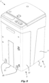
- Figure 1 comprises a filter device 1 for separating a liquid mixture according to the invention.
- the filter device 1 comprises a vessel 2 containing at least one first filter element and a housing 3 containing at least one second filter element.
- the vessel 2 is provided with an entry port 4 for introducing the liquid mixture into the first filter element.
- the housing 3 is provided with an outlet port 5 for the liquid mixture separated from liquid contaminants which are retained by the first filter element and second filter element.
- the vessel 2 comprises a flat vessel base surface 6 allowing the vessel 2 to stably stand on a horizontal flat ground surface when the vessel base surface 6 is parallel to and level with the horizontal flat ground surface.
- the housing 3 comprises a flat housing base surface 11 allowing the housing 3 to stably stand on a horizontal flat ground surface when the housing base surface 11 is parallel to and level with the horizontal flat ground surface.
- the housing base surface 11 is parallel to and level with the vessel base surface 6.
- the housing 3 further comprises a housing mantle surface 12 extending from a periphery of the housing base surface 11 in a direction opposite to the housing base surface 11.
- the housing 3 is further provided with a sample tap 13 which can be used to draw a sample of the liquid mixture from the second filter element for analysis.
- Figure 2 displays an exploded view of the filter device 1 according to the invention as shown in figure 1 .
- a first filter element 14 is contained within the vessel 2.
- the vessel mantle surface 7 of the vessel 2 comprises a re-entrant section 15 forming a recess that is configured to accommodate the housing 3.
- a mating side of the housing mantle surface 12 is configured to fit into the recess formed by the re-entrant section 15.
- the vessel 2 is provided with an outlet conduit 17, which outlet conduit 17 has an outlet end 18 which is secured to the re-entrant section 15 and which is facing the mating side of the housing mantle surface 12 when the mating side of the housing mantle surface 12 is fitted into the recess.
- the housing 3 is provided with a housing top surface 19, which housing top surface 19 is slanting towards the housing base surface 11 in a direction towards the recess formed by the re-entrant section 15 when the mating side of the housing mantle surface 12 is fitted into the recess.
- the housing 3 is provided with one or more wheels 20, at a side of the housing mantle surface 12 opposite to the mating side.
- a circumference of the one or more wheels 20 is tangent with the housing base surface 11.
- the one or more wheels 20 are also partially recessed in the side of the housing mantle surface 12 opposite to the mating side.
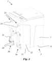
- Figure 4 shows another variant filter device 1 according to the invention.
- the variant filter device 1 comprises two housings 3a, 3b. Each of these two housings 3a, 3b contains at least one second filter element.
- the second filter element contained in a first housing 3a may be made of a filter material similar to or different from a filter material which the second filter element contained in a second housing 3b is made of.
- the two housings 3a, 3b are provided with a connection conduit 21 configured to allow the liquid mixture to flow from the second filter element contained in the first housing 3a to the other second filter element contained in the second housing 3b.
- connection conduit 21 is flexible and detachably connected to both the two housings 3a, 3b.
- the housing 3a, 3b is provided with a grip portion 22.
- the grip portion 22 may be a re-entrant grip portion 23.
- Such a re-entrant grip portion 23 may be positioned closer to the housing top surface 19 than to the housing base surface 11. In this way, the housing 3 can be easily tilted onto its one or more wheels 20 by pulling the housing 3a, 3b away from the vessel 2 by the re-entrant grip portion 23.
- the grip portion 22 is a protruding grip portion.
- Figure 5 shows a top view of the filter device 1 of figure 1 .
- Figure 6 shows a partial cutaway view of the filter device 1 in figure 1 according to line VI-VI in figure 5 .
- connection means 16 to fluidly connect an outlet of the first filter element 14 with an inlet of the second filter element in a detachable way are shown when the mating side of the housing mantle surface 12 is fitted into the recess formed by the re-entrant section 15.
- connection means 16 comprise
- Figure 7 shows more in detail the part that has been indicated by frame F7 in figure 6 .
- An O-ring 26 is provided around the inlet end 25 of the inlet conduit 24 in order to provide a seal between the inlet conduit 24 and an inner channel 27 of the outlet conduit 17 at the outlet end 18.
- the inlet end 25 is provided with a stepped portion 28 configured to accommodate the O-ring 26.
- the O-ring 26 cannot be wrongly displaced with respect to the inlet end 25 when the inlet end 25 is pushed and fitted within the inner channel 27 of the outlet conduit 17 when the housing 3 is fitted into the vessel 2, such that the inlet end 25 is correctly sealingly connected with the inner channel 27 of the outlet conduit 17 and that the outlet of the first filter element 14 is fluidly connected with the inlet of the second filter element.
- Figure 8 shows a view of the filter device 1 illustrating a side of the vessel mantle surface 7 opposite to the recess formed by the re-entrant section 15. In other words, the housing 3 is turned away from the viewer's perspective.
- the vessel 2 is provided with a drain valve 29 at the side of the vessel mantle surface 7 opposite to the recess formed by the re-entrant section 15 and close to the vessel base surface 6.
- the drain valve 29 allows to empty the liquid mixture from the vessel 2 during operation of the filter device 1 without having to lift or tilt the possible heavy vessel 2.
Landscapes
- Chemical & Material Sciences (AREA)
- Chemical Kinetics & Catalysis (AREA)
- Physics & Mathematics (AREA)
- Thermal Sciences (AREA)
- Filtration Of Liquid (AREA)
Priority Applications (1)
| Application Number | Priority Date | Filing Date | Title |
|---|---|---|---|
| SI202130245T SI4142906T1 (sl) | 2020-04-27 | 2021-03-22 | Filtrirna naprava in postopek za sestavljanje in razstavljanje take filtrirne naprave |
Applications Claiming Priority (3)
| Application Number | Priority Date | Filing Date | Title |
|---|---|---|---|
| US202063015878P | 2020-04-27 | 2020-04-27 | |
| BE20205420A BE1028246B1 (nl) | 2020-04-27 | 2020-06-11 | Filterinrichting en werkwijze voor het monteren en demonteren van een dergelijke filterinrichting |
| PCT/IB2021/052130 WO2021220068A1 (en) | 2020-04-27 | 2021-03-22 | Filter device and method for assembling and disassembling such a filter device |
Publications (2)
| Publication Number | Publication Date |
|---|---|
| EP4142906A1 EP4142906A1 (en) | 2023-03-08 |
| EP4142906B1 true EP4142906B1 (en) | 2024-10-09 |
Family
ID=74884996
Family Applications (1)
| Application Number | Title | Priority Date | Filing Date |
|---|---|---|---|
| EP21712580.6A Active EP4142906B1 (en) | 2020-04-27 | 2021-03-22 | Filter device and method for assembling and disassembling such a filter device |
Country Status (12)
| Country | Link |
|---|---|
| US (1) | US12434173B2 (pl) |
| EP (1) | EP4142906B1 (pl) |
| CN (2) | CN214680373U (pl) |
| DK (1) | DK4142906T3 (pl) |
| ES (1) | ES3001182T3 (pl) |
| FI (1) | FI4142906T3 (pl) |
| HU (1) | HUE069549T2 (pl) |
| PL (1) | PL4142906T3 (pl) |
| PT (1) | PT4142906T (pl) |
| SI (1) | SI4142906T1 (pl) |
| TW (1) | TWI799812B (pl) |
| WO (1) | WO2021220068A1 (pl) |
Families Citing this family (1)
| Publication number | Priority date | Publication date | Assignee | Title |
|---|---|---|---|---|
| TWI799812B (zh) * | 2020-04-27 | 2023-04-21 | 比利時商亞特拉斯可波克氣動股份有限公司 | 過濾裝置及用於組裝及拆解該過濾裝置的方法 |
Family Cites Families (28)
| Publication number | Priority date | Publication date | Assignee | Title |
|---|---|---|---|---|
| BE859418A (nl) * | 1976-10-14 | 1978-04-05 | Ballast Nedam Groep Nv | Werkwijze en inrichting voor het scheiden van een mengsel |
| NL7801685A (nl) | 1978-02-14 | 1979-08-16 | Ballast Nedam Groep Nv | Inrichting voor het scheiden van een mengsel. |
| FR2657543B1 (fr) * | 1990-01-26 | 1992-12-18 | Biocom Sa | Dispositif modulaire pour le recueil, l'incubation, la filtration d'echantillons multiples. |
| GB9100369D0 (en) | 1991-01-09 | 1991-02-20 | Domnick Hunter Filters Ltd | Apparatus for separating oil from an oil/water mixture |
| SE506930C2 (sv) * | 1991-03-25 | 1998-03-02 | Svedala Pumps & Process Ab | Förfarande och anordning för förtjockning av finpartikulära suspensioner |
| GB2260133B (en) | 1991-10-05 | 1994-11-30 | Domnick Hunter Ltd | Apparatus for separating oil from an oil/water mixture |
| DE19511450A1 (de) * | 1995-03-29 | 1996-10-02 | Argo Gmbh Fuer Fluidtechnik | Nebenstromfilteraggregat |
| JP3834445B2 (ja) * | 1998-06-11 | 2006-10-18 | 東洋▲ろ▼機製造株式会社 | 流体フィルタ |
| GB2350571B (en) | 1999-06-05 | 2002-12-18 | John Andrew Timmins | Separating apparatus and method of separating |
| US20020074277A1 (en) * | 2000-11-24 | 2002-06-20 | Membrane Concepts, S.L. | Filter assembly, system and method for filtering fluids |
| GB2404159A (en) | 2003-07-24 | 2005-01-26 | John Andrew Timmins | A separating device |
| US7300483B2 (en) * | 2004-02-24 | 2007-11-27 | Fipak Research And Development Company | Modular filtration assembly |
| US20060032806A1 (en) * | 2004-08-16 | 2006-02-16 | Parker Mark A | Apparatus to filter water |
| DE102006009542A1 (de) | 2005-03-19 | 2006-09-21 | Beko Technologies Gmbh | Abscheidevorrichtung |
| JP2007046522A (ja) * | 2005-08-09 | 2007-02-22 | Honda Motor Co Ltd | リッド分離型容器 |
| WO2008023768A1 (en) * | 2006-08-23 | 2008-02-28 | System-Keiso Co., Ltd. | Machining device with filter device |
| WO2008080068A2 (en) * | 2006-12-22 | 2008-07-03 | Donaldson Company, Inc. | Gas/liquid separator assembly with preseparator and liquid filter, and methods |
| GB0715269D0 (en) * | 2007-08-04 | 2007-09-12 | Parker Hannifin Ltd | Filter assembly |
| CN201492969U (zh) * | 2009-08-18 | 2010-06-02 | 王庆生 | 聚结分离装置 |
| US9233324B2 (en) * | 2009-10-13 | 2016-01-12 | Control Components, Inc. | Increased efficiency strainer system |
| KR101510933B1 (ko) | 2010-02-26 | 2015-04-10 | 베코 테크놀로지스 게엠베하 | 오일/물 여과 장치 |
| JP5860878B2 (ja) | 2010-08-06 | 2016-02-16 | ベコー テヒノロギース ゲーエムベーハー | カートリッジ式油分離器 |
| WO2013052091A1 (en) * | 2011-10-03 | 2013-04-11 | Entegris, Inc. | Modular filtration system |
| CN203648201U (zh) * | 2013-09-30 | 2014-06-18 | 四川高精净化设备有限公司 | 一种可以便捷地清洗更换滤芯的过滤器 |
| US10421032B2 (en) * | 2016-03-11 | 2019-09-24 | Kx Technologies Llc | Modular filtration platform |
| CN208465311U (zh) * | 2018-06-15 | 2019-02-05 | 南京林业大学 | 一种竹刨花过滤装置 |
| DE102018124610B4 (de) * | 2018-10-05 | 2022-03-03 | Mann+Hummel Gmbh | Stationäre Umgebungsluftreinigungsvorrichtung und Umgebungsluftreinigungsvorrichtungs-Anordnung |
| TWI799812B (zh) * | 2020-04-27 | 2023-04-21 | 比利時商亞特拉斯可波克氣動股份有限公司 | 過濾裝置及用於組裝及拆解該過濾裝置的方法 |
-
2021
- 2021-03-15 TW TW110109111A patent/TWI799812B/zh active
- 2021-03-22 FI FIEP21712580.6T patent/FI4142906T3/fi active
- 2021-03-22 PT PT217125806T patent/PT4142906T/pt unknown
- 2021-03-22 WO PCT/IB2021/052130 patent/WO2021220068A1/en not_active Ceased
- 2021-03-22 US US17/921,812 patent/US12434173B2/en active Active
- 2021-03-22 SI SI202130245T patent/SI4142906T1/sl unknown
- 2021-03-22 PL PL21712580.6T patent/PL4142906T3/pl unknown
- 2021-03-22 EP EP21712580.6A patent/EP4142906B1/en active Active
- 2021-03-22 HU HUE21712580A patent/HUE069549T2/hu unknown
- 2021-03-22 ES ES21712580T patent/ES3001182T3/es active Active
- 2021-03-22 DK DK21712580.6T patent/DK4142906T3/da active
- 2021-04-23 CN CN202120851585.3U patent/CN214680373U/zh active Active
- 2021-04-23 CN CN202110438694.7A patent/CN113634032B/zh active Active
Also Published As
| Publication number | Publication date |
|---|---|
| FI4142906T3 (fi) | 2025-01-10 |
| TW202140119A (zh) | 2021-11-01 |
| PT4142906T (pt) | 2024-12-17 |
| US20230173409A1 (en) | 2023-06-08 |
| EP4142906A1 (en) | 2023-03-08 |
| DK4142906T3 (da) | 2025-01-13 |
| CN214680373U (zh) | 2021-11-12 |
| PL4142906T3 (pl) | 2025-02-24 |
| SI4142906T1 (sl) | 2025-02-28 |
| WO2021220068A1 (en) | 2021-11-04 |
| HUE069549T2 (hu) | 2025-03-28 |
| TWI799812B (zh) | 2023-04-21 |
| CN113634032B (zh) | 2023-04-14 |
| ES3001182T3 (es) | 2025-03-04 |
| CN113634032A (zh) | 2021-11-12 |
| CA3175214A1 (en) | 2021-11-04 |
| US12434173B2 (en) | 2025-10-07 |
Similar Documents
| Publication | Publication Date | Title |
|---|---|---|
| US4378290A (en) | Modularized multi-stage separator system | |
| EP0436773B1 (en) | Purification of compressed air discharge condensate | |
| US5196117A (en) | Apparatus for separating oil from an oil/water mixture | |
| EP4142906B1 (en) | Filter device and method for assembling and disassembling such a filter device | |
| CA3175214C (en) | Filter device and method for assembling and disassembling such a filter device | |
| KR20220133100A (ko) | 유수 분리 장치 및 유수 분리 방법 | |
| KR20230116004A (ko) | 필터 유닛 및 오일/물 혼합물로부터 오일이 포함된 성분을 제거하기 위한 유수 분리 장치의 베이스 유닛 | |
| EP0624389B1 (en) | Apparatus for treating contaminated water | |
| US6495033B1 (en) | Device for separating two non-mixable liquids with different specific gravities | |
| US5143611A (en) | Apparatus for separating oil from water | |
| US6132620A (en) | Method and apparatus for separating oil and water | |
| JPH0631110A (ja) | オイルと水とを分離する装置 | |
| US7744767B2 (en) | Fluid separation system | |
| GB2251812A (en) | Oil-water separator | |
| GB2260133A (en) | Apparatus for separating oil from an oil/water mixture | |
| US7435344B2 (en) | Device for separating impurities from liquids | |
| KR200338460Y1 (ko) | 유화액 분리장치 | |
| JPH05192509A (ja) | 油/水混合物から油を分離する装置 | |
| BE1028246A1 (nl) | Filterinrichting en werkwijze voor het monteren en demonteren van een dergelijke filterinrichting | |
| US9150435B1 (en) | Method of stripping volatile organic compounds from water using a gas sparged hydrocyclone | |
| EP1626791B1 (en) | Fluid separation system | |
| JPH0523506A (ja) | 二重構造フイルタ容器連結用閉止弁 | |
| KR20220077515A (ko) | 기름 회수 용도의 유수 분리 장치 | |
| EP0584380A1 (de) | Abscheider für mit direkt abscheidbaren Schwimmstoffen verschmutzte Abwässer | |
| AU2006230715A1 (en) | Apparatus for Treating a Fluid Stream |
Legal Events
| Date | Code | Title | Description |
|---|---|---|---|
| STAA | Information on the status of an ep patent application or granted ep patent |
Free format text: STATUS: UNKNOWN |
|
| STAA | Information on the status of an ep patent application or granted ep patent |
Free format text: STATUS: THE INTERNATIONAL PUBLICATION HAS BEEN MADE |
|
| PUAI | Public reference made under article 153(3) epc to a published international application that has entered the european phase |
Free format text: ORIGINAL CODE: 0009012 |
|
| STAA | Information on the status of an ep patent application or granted ep patent |
Free format text: STATUS: REQUEST FOR EXAMINATION WAS MADE |
|
| 17P | Request for examination filed |
Effective date: 20221018 |
|
| AK | Designated contracting states |
Kind code of ref document: A1 Designated state(s): AL AT BE BG CH CY CZ DE DK EE ES FI FR GB GR HR HU IE IS IT LI LT LU LV MC MK MT NL NO PL PT RO RS SE SI SK SM TR |
|
| DAV | Request for validation of the european patent (deleted) | ||
| DAX | Request for extension of the european patent (deleted) | ||
| GRAP | Despatch of communication of intention to grant a patent |
Free format text: ORIGINAL CODE: EPIDOSNIGR1 |
|
| GRAP | Despatch of communication of intention to grant a patent |
Free format text: ORIGINAL CODE: EPIDOSNIGR1 |
|
| STAA | Information on the status of an ep patent application or granted ep patent |
Free format text: STATUS: GRANT OF PATENT IS INTENDED |
|
| INTG | Intention to grant announced |
Effective date: 20240614 |
|
| GRAJ | Information related to disapproval of communication of intention to grant by the applicant or resumption of examination proceedings by the epo deleted |
Free format text: ORIGINAL CODE: EPIDOSDIGR1 |
|
| STAA | Information on the status of an ep patent application or granted ep patent |
Free format text: STATUS: REQUEST FOR EXAMINATION WAS MADE |
|
| GRAP | Despatch of communication of intention to grant a patent |
Free format text: ORIGINAL CODE: EPIDOSNIGR1 |
|
| STAA | Information on the status of an ep patent application or granted ep patent |
Free format text: STATUS: GRANT OF PATENT IS INTENDED |
|
| INTC | Intention to grant announced (deleted) | ||
| GRAS | Grant fee paid |
Free format text: ORIGINAL CODE: EPIDOSNIGR3 |
|
| INTG | Intention to grant announced |
Effective date: 20240805 |
|
| GRAA | (expected) grant |
Free format text: ORIGINAL CODE: 0009210 |
|
| STAA | Information on the status of an ep patent application or granted ep patent |
Free format text: STATUS: THE PATENT HAS BEEN GRANTED |
|
| AK | Designated contracting states |
Kind code of ref document: B1 Designated state(s): AL AT BE BG CH CY CZ DE DK EE ES FI FR GB GR HR HU IE IS IT LI LT LU LV MC MK MT NL NO PL PT RO RS SE SI SK SM TR |
|
| REG | Reference to a national code |
Ref country code: CH Ref legal event code: EP |
|
| REG | Reference to a national code |
Ref country code: DE Ref legal event code: R096 Ref document number: 602021019934 Country of ref document: DE |
|
| REG | Reference to a national code |
Ref country code: IE Ref legal event code: FG4D |
|
| REG | Reference to a national code |
Ref country code: PT Ref legal event code: SC4A Ref document number: 4142906 Country of ref document: PT Date of ref document: 20241217 Kind code of ref document: T Free format text: AVAILABILITY OF NATIONAL TRANSLATION Effective date: 20241211 |
|
| REG | Reference to a national code |
Ref country code: NL Ref legal event code: FP |
|
| REG | Reference to a national code |
Ref country code: FI Ref legal event code: FGE |
|
| REG | Reference to a national code |
Ref country code: DK Ref legal event code: T3 Effective date: 20250108 |
|
| REG | Reference to a national code |
Ref country code: LT Ref legal event code: MG9D |
|
| REG | Reference to a national code |
Ref country code: SE Ref legal event code: TRGR |
|
| P01 | Opt-out of the competence of the unified patent court (upc) registered |
Free format text: CASE NUMBER: APP_257/2025 Effective date: 20250103 |
|
| PGFP | Annual fee paid to national office [announced via postgrant information from national office to epo] |
Ref country code: SI Payment date: 20241209 Year of fee payment: 5 |
|
| REG | Reference to a national code |
Ref country code: SK Ref legal event code: T3 Ref document number: E 45718 Country of ref document: SK |
|
| REG | Reference to a national code |
Ref country code: ES Ref legal event code: FG2A Ref document number: 3001182 Country of ref document: ES Kind code of ref document: T3 Effective date: 20250304 |
|
| REG | Reference to a national code |
Ref country code: HU Ref legal event code: AG4A Ref document number: E069549 Country of ref document: HU |
|
| PG25 | Lapsed in a contracting state [announced via postgrant information from national office to epo] |
Ref country code: HR Free format text: LAPSE BECAUSE OF FAILURE TO SUBMIT A TRANSLATION OF THE DESCRIPTION OR TO PAY THE FEE WITHIN THE PRESCRIBED TIME-LIMIT Effective date: 20241009 Ref country code: IS Free format text: LAPSE BECAUSE OF FAILURE TO SUBMIT A TRANSLATION OF THE DESCRIPTION OR TO PAY THE FEE WITHIN THE PRESCRIBED TIME-LIMIT Effective date: 20250209 |
|
| PG25 | Lapsed in a contracting state [announced via postgrant information from national office to epo] |
Ref country code: BG Free format text: LAPSE BECAUSE OF FAILURE TO SUBMIT A TRANSLATION OF THE DESCRIPTION OR TO PAY THE FEE WITHIN THE PRESCRIBED TIME-LIMIT Effective date: 20241009 |
|
| PG25 | Lapsed in a contracting state [announced via postgrant information from national office to epo] |
Ref country code: LV Free format text: LAPSE BECAUSE OF FAILURE TO SUBMIT A TRANSLATION OF THE DESCRIPTION OR TO PAY THE FEE WITHIN THE PRESCRIBED TIME-LIMIT Effective date: 20241009 Ref country code: GR Free format text: LAPSE BECAUSE OF FAILURE TO SUBMIT A TRANSLATION OF THE DESCRIPTION OR TO PAY THE FEE WITHIN THE PRESCRIBED TIME-LIMIT Effective date: 20250110 |
|
| PG25 | Lapsed in a contracting state [announced via postgrant information from national office to epo] |
Ref country code: RS Free format text: LAPSE BECAUSE OF FAILURE TO SUBMIT A TRANSLATION OF THE DESCRIPTION OR TO PAY THE FEE WITHIN THE PRESCRIBED TIME-LIMIT Effective date: 20250109 |
|
| PG25 | Lapsed in a contracting state [announced via postgrant information from national office to epo] |
Ref country code: SM Free format text: LAPSE BECAUSE OF FAILURE TO SUBMIT A TRANSLATION OF THE DESCRIPTION OR TO PAY THE FEE WITHIN THE PRESCRIBED TIME-LIMIT Effective date: 20241009 |
|
| PGFP | Annual fee paid to national office [announced via postgrant information from national office to epo] |
Ref country code: ES Payment date: 20250401 Year of fee payment: 5 |
|
| REG | Reference to a national code |
Ref country code: DE Ref legal event code: R097 Ref document number: 602021019934 Country of ref document: DE |
|
| PG25 | Lapsed in a contracting state [announced via postgrant information from national office to epo] |
Ref country code: EE Free format text: LAPSE BECAUSE OF FAILURE TO SUBMIT A TRANSLATION OF THE DESCRIPTION OR TO PAY THE FEE WITHIN THE PRESCRIBED TIME-LIMIT Effective date: 20241009 |
|
| PGFP | Annual fee paid to national office [announced via postgrant information from national office to epo] |
Ref country code: CH Payment date: 20250401 Year of fee payment: 5 |
|
| PG25 | Lapsed in a contracting state [announced via postgrant information from national office to epo] |
Ref country code: CZ Free format text: LAPSE BECAUSE OF FAILURE TO SUBMIT A TRANSLATION OF THE DESCRIPTION OR TO PAY THE FEE WITHIN THE PRESCRIBED TIME-LIMIT Effective date: 20241009 |
|
| PLBE | No opposition filed within time limit |
Free format text: ORIGINAL CODE: 0009261 |
|
| STAA | Information on the status of an ep patent application or granted ep patent |
Free format text: STATUS: NO OPPOSITION FILED WITHIN TIME LIMIT |
|
| 26N | No opposition filed |
Effective date: 20250710 |
|
| PG25 | Lapsed in a contracting state [announced via postgrant information from national office to epo] |
Ref country code: MC Free format text: LAPSE BECAUSE OF FAILURE TO SUBMIT A TRANSLATION OF THE DESCRIPTION OR TO PAY THE FEE WITHIN THE PRESCRIBED TIME-LIMIT Effective date: 20241009 |
|
| PG25 | Lapsed in a contracting state [announced via postgrant information from national office to epo] |
Ref country code: LU Free format text: LAPSE BECAUSE OF NON-PAYMENT OF DUE FEES Effective date: 20250322 |
|
| PG25 | Lapsed in a contracting state [announced via postgrant information from national office to epo] |
Ref country code: IE Free format text: LAPSE BECAUSE OF NON-PAYMENT OF DUE FEES Effective date: 20250322 |
|
| REG | Reference to a national code |
Ref country code: AT Ref legal event code: UEP Ref document number: 1729960 Country of ref document: AT Kind code of ref document: T Effective date: 20241009 |
|
| REG | Reference to a national code |
Ref country code: CH Ref legal event code: U11 Free format text: ST27 STATUS EVENT CODE: U-0-0-U10-U11 (AS PROVIDED BY THE NATIONAL OFFICE) Effective date: 20260401 |
|
| PGFP | Annual fee paid to national office [announced via postgrant information from national office to epo] |
Ref country code: SE Payment date: 20260327 Year of fee payment: 6 |
|
| PGFP | Annual fee paid to national office [announced via postgrant information from national office to epo] |
Ref country code: GB Payment date: 20260327 Year of fee payment: 6 |
|
| PGFP | Annual fee paid to national office [announced via postgrant information from national office to epo] |
Ref country code: NO Payment date: 20260327 Year of fee payment: 6 Ref country code: DK Payment date: 20260325 Year of fee payment: 6 Ref country code: DE Payment date: 20260327 Year of fee payment: 6 |
|
| PGFP | Annual fee paid to national office [announced via postgrant information from national office to epo] |
Ref country code: AT Payment date: 20260327 Year of fee payment: 6 |
|
| PGFP | Annual fee paid to national office [announced via postgrant information from national office to epo] |
Ref country code: RO Payment date: 20260304 Year of fee payment: 6 Ref country code: BE Payment date: 20260327 Year of fee payment: 6 Ref country code: FI Payment date: 20260325 Year of fee payment: 6 Ref country code: IT Payment date: 20260319 Year of fee payment: 6 |
|
| PGFP | Annual fee paid to national office [announced via postgrant information from national office to epo] |
Ref country code: HU Payment date: 20260311 Year of fee payment: 6 Ref country code: NL Payment date: 20260326 Year of fee payment: 6 |
|
| PGFP | Annual fee paid to national office [announced via postgrant information from national office to epo] |
Ref country code: FR Payment date: 20260325 Year of fee payment: 6 |
|
| PGFP | Annual fee paid to national office [announced via postgrant information from national office to epo] |
Ref country code: PT Payment date: 20260310 Year of fee payment: 6 |
|
| PGFP | Annual fee paid to national office [announced via postgrant information from national office to epo] |
Ref country code: PL Payment date: 20260302 Year of fee payment: 6 |
|
| PGFP | Annual fee paid to national office [announced via postgrant information from national office to epo] |
Ref country code: SK Payment date: 20260304 Year of fee payment: 6 |