EP4139978B1 - Fluidführungsanordnung für brennstoffzelle - Google Patents
Fluidführungsanordnung für brennstoffzelle Download PDFInfo
- Publication number
- EP4139978B1 EP4139978B1 EP20721178.0A EP20721178A EP4139978B1 EP 4139978 B1 EP4139978 B1 EP 4139978B1 EP 20721178 A EP20721178 A EP 20721178A EP 4139978 B1 EP4139978 B1 EP 4139978B1
- Authority
- EP
- European Patent Office
- Prior art keywords
- distributors
- channel structure
- fluid guiding
- guiding assembly
- assembly according
- Prior art date
- Legal status (The legal status is an assumption and is not a legal conclusion. Google has not performed a legal analysis and makes no representation as to the accuracy of the status listed.)
- Active
Links
Images

Classifications
-
- H—ELECTRICITY
- H01—ELECTRIC ELEMENTS
- H01M—PROCESSES OR MEANS, e.g. BATTERIES, FOR THE DIRECT CONVERSION OF CHEMICAL ENERGY INTO ELECTRICAL ENERGY
- H01M8/00—Fuel cells; Manufacture thereof
- H01M8/02—Details
- H01M8/0202—Collectors; Separators, e.g. bipolar separators; Interconnectors
- H01M8/0204—Non-porous and characterised by the material
-
- H—ELECTRICITY
- H01—ELECTRIC ELEMENTS
- H01M—PROCESSES OR MEANS, e.g. BATTERIES, FOR THE DIRECT CONVERSION OF CHEMICAL ENERGY INTO ELECTRICAL ENERGY
- H01M8/00—Fuel cells; Manufacture thereof
- H01M8/02—Details
- H01M8/0202—Collectors; Separators, e.g. bipolar separators; Interconnectors
- H01M8/023—Porous and characterised by the material
-
- H—ELECTRICITY
- H01—ELECTRIC ELEMENTS
- H01M—PROCESSES OR MEANS, e.g. BATTERIES, FOR THE DIRECT CONVERSION OF CHEMICAL ENERGY INTO ELECTRICAL ENERGY
- H01M8/00—Fuel cells; Manufacture thereof
- H01M8/02—Details
- H01M8/0202—Collectors; Separators, e.g. bipolar separators; Interconnectors
- H01M8/0247—Collectors; Separators, e.g. bipolar separators; Interconnectors characterised by the form
-
- H—ELECTRICITY
- H01—ELECTRIC ELEMENTS
- H01M—PROCESSES OR MEANS, e.g. BATTERIES, FOR THE DIRECT CONVERSION OF CHEMICAL ENERGY INTO ELECTRICAL ENERGY
- H01M8/00—Fuel cells; Manufacture thereof
- H01M8/02—Details
- H01M8/0202—Collectors; Separators, e.g. bipolar separators; Interconnectors
- H01M8/0258—Collectors; Separators, e.g. bipolar separators; Interconnectors characterised by the configuration of channels, e.g. by the flow field of the reactant or coolant
-
- H—ELECTRICITY
- H01—ELECTRIC ELEMENTS
- H01M—PROCESSES OR MEANS, e.g. BATTERIES, FOR THE DIRECT CONVERSION OF CHEMICAL ENERGY INTO ELECTRICAL ENERGY
- H01M8/00—Fuel cells; Manufacture thereof
- H01M8/24—Grouping of fuel cells, e.g. stacking of fuel cells
- H01M8/241—Grouping of fuel cells, e.g. stacking of fuel cells with solid or matrix-supported electrolytes
-
- H—ELECTRICITY
- H01—ELECTRIC ELEMENTS
- H01M—PROCESSES OR MEANS, e.g. BATTERIES, FOR THE DIRECT CONVERSION OF CHEMICAL ENERGY INTO ELECTRICAL ENERGY
- H01M8/00—Fuel cells; Manufacture thereof
- H01M8/10—Fuel cells with solid electrolytes
- H01M2008/1095—Fuel cells with polymeric electrolytes
-
- Y—GENERAL TAGGING OF NEW TECHNOLOGICAL DEVELOPMENTS; GENERAL TAGGING OF CROSS-SECTIONAL TECHNOLOGIES SPANNING OVER SEVERAL SECTIONS OF THE IPC; TECHNICAL SUBJECTS COVERED BY FORMER USPC CROSS-REFERENCE ART COLLECTIONS [XRACs] AND DIGESTS
- Y02—TECHNOLOGIES OR APPLICATIONS FOR MITIGATION OR ADAPTATION AGAINST CLIMATE CHANGE
- Y02E—REDUCTION OF GREENHOUSE GAS [GHG] EMISSIONS, RELATED TO ENERGY GENERATION, TRANSMISSION OR DISTRIBUTION
- Y02E60/00—Enabling technologies; Technologies with a potential or indirect contribution to GHG emissions mitigation
- Y02E60/30—Hydrogen technology
- Y02E60/50—Fuel cells
Definitions
- the current invention relates to a fluid guiding assembly, in particular for guiding gases and liquids in fuel cells.
- Fuel cells are one of the main candidates to replace power generators that are operating based on fossil fuels and they can be used in several applications, including mobile and stationary applications.
- One such fuel cell is the Proton Electrolyte Membrane (PEM) fuel cell that operates at 70-80 °C.
- PEM Proton Electrolyte Membrane
- Each cell in a stack assembly comprises an electrolyte, usually a thin membrane, a catalyst layer on the anode side and a catalyst layer on the cathode side, wherein the assembly is called a Membrane Electrode Assembly (MEA).
- MEA Membrane Electrode Assembly
- the fuel usually hydrogen and the oxidant, usually air, pass through each layer where the electro-chemical reaction occurs to produce electricity with water as a by-product.
- GDL Gas Diffusion Layer
- FF Flow Field
- a problem to be solved is the provision of a fluid guiding assembly that allows the production of thinner fuel cells. Additionally, these fuel cells should have a simple design and should be easy to manufacture.
- a fluid guiding assembly for fuel cells comprising a channel structure and a gas diffusion layer arranged on the channel structure.
- the channel structure defining flow field channels extending from a first end of the channel structure to an opposite second end.
- a porous distributor is arranged at both ends of the channel structure, extending over the entire width of the channel structure, from a first lateral side of the channel structure to an opposite second lateral side of the channel structure, wherein the height of the distributors equals the sum of the height of the diffusion layer and the height of the channel structure.
- the distributors are formed in one piece and have a porosity of between 10% and 90%. In a further embodiment, the porosity ranges between 50% and 80%.
- the porosity changes over the width of the distributors, i.e. when the fluid guiding assembly is introduced in a fuel cell, the porosity in the vicinity of a corresponding manifold is lower than further away from it. For example, if the manifold is allocated on one lateral side, the porosity there is the smallest and the porosity is the highest on the opposite lateral side. If the manifold is allocated in the middle, the porosity is the highest on both lateral sides and is the smallest in the middle.
- the length of the distributors is in the range of 1% to 10% of the length of the flow field channels, i.e. of the channel structure.
- the length of the distributors is in the range of 0.1 millimetre to 20 millimetres. In a further embodiment, the length of the distributors is in the range of 1 millimetre to 10 millimetres.
- the height of the distributors equals the height of the channel structure.
- the height of the distributors is smaller than the height of the channel structure.
- the height of the distributors equals the sum of the height of the diffusion layer and the height of the channel structure.
- the height of the distributors is bigger than the height of the channel structure.
- the height of the distributors is in the range of 50 micrometres to 400 micrometres. In a further embodiment, the height of the distributors is in the range of 200 micrometres to 400 micrometres.
- the flow channel structure and the distributors are permanently connected with each other.
- the gas diffusion layer, the flow channel structure and the distributors are permanently connected with each other.
- the permanent connection can be realized by coating, pressing or hot pressing.
- the distributors comprise at least one of the group comprising an open-pore foam, a hole pattern and a slit pattern.
- the distributors comprise circular, oval or angular holes.
- the distributors comprise straight, curved or angled slits.
- the distributors are made of metal, plastic or resin or a combination thereof.
- the channel structure comprises straight, serpentine or interdigitated flow field channels.
- the channel structure and the distributors are formed integrally in a single piece.
- a flow field structure comprises a fluid guiding assembly according to one of the before-mentioned embodiments and a separator plate with a recess for receiving the fluid guiding assembly.
- the flow field structure further comprises manifolds and distribution channels for supplying gas to the distributors on the first end of the channel structure and for collecting gas from the distributors on the second end of the channel structure.
- a fuel cell according to the invention comprises at least one membrane electrode assembly braced by two flow field structures according to the before-mentioned embodiment.
- the fuel cell comprises two current collector plates and two backing plates, wherein one current collector plate is arranged adjacent to each flow field structure and wherein one backing plate is arranged adjacent to each current collector plate.
- the two backing plates are braced by clamping elements.
- a method for manufacturing a fluid guiding assembly according to the invention comprises the steps of:
- the method comprises the step of:
- the method comprises the steps of:
- the permanently connecting comprises pressing or wherein the permanently connecting comprises heating and pressing.
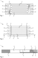
- FIG. 1 shows a top view of a flow field plate according to the prior art.
- a bi-polar plate 7, made of any material such as metal or graphite comprises several gas/liquid inlet/outlet manifolds 90,91,92 that are located at the outer part of the plate.
- the active area A with catalyst layer is located in the middle of the cell with a special Flow Field (FF) underneath.
- FF Flow Field
- Flow fields guarantee a sufficient and uniform gas supply on the active area A.
- FDC Flow Distribution Channels
- gas flow channels are designed on or in channel structures.
- the channels guide the reactants to flow in a specific direction and assist in the water removal from the cell.
- various method of production for the flow channels or patterns are used. For example, if plates/separators are made of graphite composite materials, injection moulding, compression moulding or machining is used. If the plates are made of metallic plates, stamping has been the most promising and economically viable technology that has been used. For every single bipolar plate assembly, normally two separate sheet metals are stamped, laser welded and coated (before or after stamping) with a protective coating.
- the laser welding is eliminated, and conventional sealing is used.
- One of the major drawbacks of the designs of the prior art is the limitation on how much the thickness of a single plate can be reduced. This has a direct influence on the size of an assembled stack and therefore on the volume power density.
- the width and depth of the channels that can be produced are limited by the elongation of the sheet metal or by the limitation of the machining process.
- the gas channels are separated from one another by ribs that are in contact with the Gas Diffusion Layers (GDL). Water produced due to electro-chemical reaction passes through the GDL and ends up into the gas channels.
- GDL Gas Diffusion Layers
- GDL gas diffusion layer
- GDL gas diffusion layers
- Figure 2 shows a top view of a flow field structure 7 according to the invention and figure 3 shows a partial sectional view of the flow field structure of figure 2 along section line XX.
- the inventive structure combines several components inside a fuel cell together in a more compact and reliable manner. It comprises a unique and state-of-the-art channel structure 720, a gas diffusion layer and gas distributors 73 all at once. It not only overcomes open issues related to the state-of-the-art, but also improves the performance of a fuel cell significantly. At the same time, such a design simplifies a cell assembly, thus, brings in compactness, reliability and also provides a significant cost reduction in the production of fuel cells.
- the channel structure 720 comprising the flow field channels 72 are located in the centre of the assembly, i.e. in the region of the active are A of the fuel cell.
- This design has several functionalities and advantages; Firstly, it is extremely compact and less expensive to produce compared to existing concept. Secondly, it acts as a flow straightener for the active area A, i.e. it unifies the flow distribution of the gases before they enter the active area A.
- the channel structure 720 acts as a mechanical support and holds them in place and under tension.
- it makes the overall cell assembly including the plate smaller and more compact.
- the length of the distributors 73 is preferably 1-30% and more preferably 1-10% of the length of the flow field channels 72, but not limited. For instance, if length of a flow field channel 72 is 100 mm, a preferred length of the distributors may be between 1-10mm.
- the thickness of the distributors 73 equals the sum of the height of the diffusion layer and the height of the channel structure. Since the distributors 73 may act as a mechanical support and holder for the channel structure 720, it may be necessary to make it slightly thicker so that the joint between the channel structure 720 and the distributors 73 can be arranged at the top of it. For example, if the thickness or height of the channel structure 720 is 200 [pm], the distributor thickness or height may vary between 200-400[pm], but not limited. Such a design gives more flexibility in the cell assembly, especially when the distributors 73 are in direct contact with a catalyst coated membrane (CCM) or sub-gasket or any other component in the cell assembly.
- CCM catalyst coated membrane
- FIG. 2 shows the layout of a cell with the distributors 73 according to the invention.
- the length of the separator plate 70 is reduced compared with the original plate design shown in figure 1 .
- the main difference between the plate of figure 1 and the one of figure 2 is that the active area A and gas inlet/outlet manifolds 90,91,92 are kept the same, whereas the zone where the distributors are located is significantly optimised and shorter in concept according to the invention.
- the oxidant enters the cell from the oxidant manifold 91 and is distributed in the distribution channel 71 as shown in the figure with arrows.
- the distributor 73 where it regulates and homogenise the gas flow before it enters the flow field channels 72 and the active area A.
- the length of the distribution channel 71 is optimised based on the design and the geometry of the cell. It shouldn't be too long to prevent the creation of big back pressure. Likewise, it shouldn't be too small as otherwise, the assembled layers on top of it, such as the catalyst coated membrane or the sub-gasket may deform and clog the distribution channel 71.
- the distributors can be extended over the entire length of the distribution channel between the channel structure 720 and the corresponding manifold 91. It is a design parameter that can be tuned by those skilled in the art.
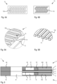
- FIGS 4A-B show sectional views of embodiments of distributors 73 according to the invention.
- the distributors 73 can be produced from various materials such as metal, aluminium, titanium, plastic, thermoplastic, resin or porous pieces, but not limited.
- the structure of the distributors is tuned based on the material used for its production. There is no limitation on design of the distributors and how it should be produced. For instance, it can be made of porous resin or metal or anything else.
- the porosity of the distributors should be estimated based on design and size of the cell, preferably it should be between 10-90% and more preferably between 50-80%, but not limited.
- the distributors are not produced from a porous material per se, other manufacturing techniques such as 3D-printing, injection/compression moulding, laminating, erosion or any other method can be used.
- the porosity can be created by a plurality of pins 730 that extend through the distributors 73 or by a plurality of slits 731 that extend through the distributors 73. In the depicted embodiment of figure 4A , the pins 730 are evenly distributed over the cross-section of the distributor 73.
- the slits 731 are serpentine-shaped and are evenly distributed over the width of the cross-section of the separator 73.
- the distributors 73 can be used together with separator plates 70 made of metal, graphite or anything else.
- the material of the distributors 73 and the channel structure 720 shouldn't be the same necessarily.
- the flow path of a conventional fuel cell, shown in Figure 1 can be reduced or eliminated by introducing a distributor according to the invention in the channel between the channel structure and the corresponding manifold.
- FIGS 5A-B show partial perspective views of embodiments of flow field channels 72 in a respective channel structure 720.
- the flow field channels 72 are produced by the stamping of a thin metal sheet.
- the channel structure 720 is formed integrally together with the separator plate 70 in a single piece.
- the distributor 73 is adjoining the flow channel structure 720 or the separator plate 70, respectively.
- fresh oxidant mostly air
- the water produced on the catalyst layer is moved towards the channels due to capillary forces in the gas diffusion layer.
- condensed water and oxidant are mixed and the water produced is pushed out of the channel.
- the gas velocity in the channel explains a great deal about the behaviour of fresh oxidant, the movement of the water and also the mixing phenomena that occur in the channels.
- Gas flows in fuel cells are mainly laminar.
- Reynolds number different mixing mechanisms may occur between the gas and the condensed water.
- the mixing of gas/liquid at a Reynolds number 1000 is different than the mixing at Reynolds numbers of less than 500.
- a high gas flow velocity helps pushing the condensed water out of the flow field channels.
- due to complex mixing effects it could also prevent fresh air from reaching the active area, especially towards the outlet side of the channel where there is an accumulation of water.
- the diffusion mixing is directly related to the fluid flow, the Reynolds- and the Prandtl-Number.
- the dimensioning of the flow field channels 72 and the gas diffusion layer 5 should be done as such that the phenomenon of conventional and diffusion mixings are considered.
- the ratio between the Reynolds number and the Prandtl number should be in the range of for example 0.01 to 1000 and more preferably 0.05 to 500, but not limited.
- wires 720 are aligned at identical distances from each other to create the flow field channels 72.
- the distance between two neighbouring wires is preferably 10-1000 [pm] and more preferably 100-300[pm], but not limited.
- the preferred cross-section of the wires is one of round, square or rectangular, but not limited.
- a preferred diameter is between 10-500 [pm] and preferably 100-300 [pm].
- preferred a side length is between 10-500 [pm] and preferably 100-300 [pm], but not limited.
- a similar structure can be made using other methods such as laser cutting or else, but not limited.
- the wires can be made of various materials and there is no limitation as long as the material is electrically conductive.
- a few examples of materials that can be used are stainless steel, aluminium, titanium, copper or thermoplastics such as PET, PEN, epoxy resins, urethane resin, polyamide resins, acrylic resins, carbon, carbon fibre or anything else.
- anti-corrosion protective coating may be applied to prevent corrosion.
- Specific materials that can be used includes gold, silver, copper, aluminium, platinum ruthenium, and can be applied by using DLC, CVD or PVD coating or else.
- the wires are made of nonconductive materials such as thermoplastic, conducting coating should be applied in order to make them functional in an assembly. However, it may be less conductive than a wire made of material.
- the material used as conductive coating For instance, carbon type materials in combination with a binder like PVDF or PTFE or conductive particles like Au, Ni or Palladium can be used, but not limited.
- FIG. 6 shows a sectional view of a membrane electrode assembly braced by two flow field structures according to the invention that can be used in a fuel cell 1.
- the membrane electrode assembly comprises a membrane 2, braced by an anode electrode layer 3 and a cathode electrode layer 4.
- the first and second flow field structure 6,7 each comprise a separator plate 60,70, a channel structure 620,720, distributors 63,73 and gas diffusion layers 5 that are arranged in corresponding recesses in the corresponding flow field structure.
- Each channel structure 620,720 comprises the corresponding flow field channels 62,72.
- each flow field structure 6,7 comprises distribution channels 61,71 that connect the distributors 63,73 to the corresponding manifold 91.
- the gas diffusion layer 5 used in the invention is thinner than conventional gas diffusion layers and its preferred thickness is between 10-150 [pm] and more preferably 25-65[ ⁇ m], but not limited.
- gases and water will have enough space to pass through it, without blocking it.
- the gas diffusion layer 5 used in the invention acts as a mechanical support for the channel structure 720 and vice-vera. Due to the very small structure forming the flow field channels 72 and the small thickness of the gas diffusion layer 5, there is a bilateral support.
- the gas diffusion layer can be made of any substrate, as long as it has a porous structure for diffusion of oxidant and fuel from and to the catalyst layers. It should also have excellent electrical-conductivity properties to reduce resistance between the layer.
- substrates that can be used as conductive particles. Some of the well-known and state-of-the-art materials are carbon, carbon black, carbon powder, carbon particle, carbon paper/cloth or anything else. It is also preferable to have additional substrate in the mixture that has hydrophobic properties.
- the hydrophobic substrate acts as a binder in the mixture and holds the structure together after its curing. It also helps to push the water towards the gas channels.
- Some of the state-of-the-art hydrophobic particles that can be used are PVDF, PTFE or anything else from similar families. There is no definitive limit on quantity of the binder in the mixture. However, the recommended percentage by mass is preferably between 5-80% and more preferably 10-30%, but not limited.
- the electrical conductivity it is possible to add an additional substrate to the mixture. Some examples are, gold, platinum, ruthenium or anything else from the same family.
- due to the thickness of the gas diffusion layer it is preferable to manufacture it along with the flow field channels. There are several methods that can be used to produce the gas diffusion layer. For instance, it can be produced by touch coating, screen printing, 3D printing or other methods, where for each machinery used, the composition and viscosity of the mixture should be tuned.
- Figures 7A-H show a depiction of the manufacturing process of one embodiment of a fluid guiding assembly according to the invention. Those skilled in the art can appreciate that it is just an example and several other techniques can be proposed. In the following, the necessary steps to be taken to produce a structure that comprises flow field channels in a channel structure, a gas diffusion layer and distributors, which can be used directly inside a cell assembly are described.
- Step 1 - Figure 7A several wires are positioned side-by-side in order to form flow field channels 72 for a fuel cell.
- the structure of the channels is not limited and can be parallel, serpentine, interdigitated or a combination thereof.
- Step 2 - Figure 7B A fixture is created so that the wires are positioned and held accurately in place. There are several methods for manufacturing the fixture, for example it can be 3D-printed or machined or anything else.
- Step 3 - Figure 7C once the wires are fixed and held in tension, at the end of the wires, i.e. at the inlet and the outlet of the flow field channels 72, two distributors 73 are placed and fixed.
- Step 4 based on the material used, several methods can be used to merge the pieces together, for example, hot pressing. Thereby the assembly is put under pressure for certain period of time at a fix temperature.
- Step 5 after merging the pieces together, it is cooled down to room temperature and afterwards, the gas diffusion layer 5 is applied.
- a conventional gas diffusion layer 5 can be used or a paste can be applied on top of the flow field channels 72 with screen printing or other technique.
- Step 6 after applying the gas diffusion layer 5, the assembly is kept at room temperature and a quality control procedure is performed to verify accuracy and homogeneity of the layer and structure.
- Step 7 the assembly is put inside an oven for curing.
- an oven for curing.
- the materials used on the channel structure 720 and the gas diffusion layer 5 several options are available. For instance, a conventional oven, infra-red oven or UV oven can be used.
- a paste as gas diffusion layer 5 the structure, for example, is heated to a temperature of around 350°C in order to cure the mixture and the binder.
- Step 8 After firing the assembly, it leaves the oven and cools down to room temperature.
- the structure is ready to be mounted in a cell assembly. Similar assembly can be used on both anode and cathode side or they can be different; for instance, structure on the cathode side may have larger flow channels in order to reduce pressure drop or they may have different gas diffusion layers for various applications.
- the following components are selected.
- a resin type material with a porosity of around 75% with a height of 2mm, a length of 5mm and a width of 50mm is prepared.
- Carbon Fibre wires with a diameter of 0.4mm and a length of 55mm is prepared to be positioned with an identical distance of 0.3mm from each other.
- carbon black powder, PTFE dispersion and a surfactant are mixed together, wherein the percentage of carbon black and PTFE was kept on 80-20%. The pieces are assembled together using a fixture.
- Gas diffusion layer paste was applied on the channel structure using a screen-printer and the assembly is put inside an oven at a temperature of 350°C for 15min. A similar procedure is repeated for the second structure for the anode side of the cell. Flat compressed graphite plates with a thickness of 4mm is used as a separator. Additionally, flat sealants made of EPDM are cut and prepared for the assembly.
- a membrane electrode assembly is manufactured as follows: A Nafion membrane with a thickness of 0.15mm is used as an electrolyte. Platinum and carbon black are mixed using a Nafion solvent and are sprayed on both sides of the membrane with a loading of 0.4 and 0.04mg/cm 2 , on the cathode side or on the anode side, respectively.
Landscapes
- Life Sciences & Earth Sciences (AREA)
- Engineering & Computer Science (AREA)
- Manufacturing & Machinery (AREA)
- Sustainable Development (AREA)
- Sustainable Energy (AREA)
- Chemical & Material Sciences (AREA)
- Chemical Kinetics & Catalysis (AREA)
- Electrochemistry (AREA)
- General Chemical & Material Sciences (AREA)
- Fuel Cell (AREA)
- Inert Electrodes (AREA)
- Paper (AREA)
Claims (21)
- Eine Fluidführungsanordnung für Brennstoffzellen, umfassend eine Kanalstruktur (620;720) und eine auf der Kanalstruktur (620;720) angeordnete Gasdiffusionsschicht (5), wobei die Kanalstruktur (620;720) Strömungsfeldkanäle (62;72) definiert, die sich von einem ersten Ende der Kanalstruktur (620;720) zu einem gegenüberliegenden zweiten Ende erstrecken, wobei ein poröser Verteiler (63;73) an beiden Enden der Kanalstruktur (620;720) angeordnet ist, der sich über die gesamte Breite der Kanalstruktur (620;720) erstreckt, dadurch gekennzeichnet, dass die Höhe der Verteiler (63;73) gleich der Summe aus der Höhe der Diffusionsschicht (5) und der Höhe der Kanalstruktur (620;720) ist.
- Die Fluidführungsanordnung nach Anspruch 1, wobei die Verteiler (63;73) in einem Stück geformt sind und eine Porosität zwischen 10% und 90% aufweisen.
- Die Fluidführungsanordnung nach Anspruch 1 oder 2, wobei sich die Porosität über die Breite der Verteiler (63;73) ändert.
- Die Fluidführungsanordnung nach einem der vorhergehenden Ansprüche, wobei die Länge der Verteiler (63;73) im Bereich von 1% bis 10% der Länge der Strömungsfeldkanäle (62;72) liegt.
- Die Fluidführungsanordnung nach Anspruch 4, wobei die Länge der Verteiler (63;73) im Bereich von 0,1 Millimeter bis 20 Millimeter liegt.
- Die Fluidführungsanordnung nach einem der Ansprüche 1 bis 5, wobei die Höhe der Verteiler (63;73) im Bereich von 50 Mikrometern bis 400 Mikrometern liegt.
- Die Fluidführungsanordnung nach einem der vorhergehenden Ansprüche, wobei die Strömungskanalstruktur (620;720) und die Verteiler (63;73) fest miteinander verbunden sind.
- Die Fluidführungsanordnung nach Anspruch 7, wobei die Gasdiffusionsschicht (5), die Strömungskanalstruktur (620;720) und die Verteiler (63;73) dauerhaft miteinander verbunden sind.
- Die Fluidführungsanordnung nach einem der vorhergehenden Ansprüche, wobei die Verteiler (63;73) mindestens einen aus der Gruppe umfassend einen offenporigen Schaum, ein Lochmuster (730) und ein Schlitzmuster (731) umfassen.
- Die Fluidführungsanordnung nach Anspruch 9, wobei die Verteiler (63;73) kreisförmige, ovale oder eckige Löcher (730) aufweisen.
- Die Fluidführungsanordnung nach Anspruch 9, wobei die Verteiler (63;73) gerade, gekrümmte oder abgewinkelte Schlitze (731) aufweisen.
- Die Fluidführungsanordnung nach einem der vorhergehenden Ansprüche, wobei die Verteiler (63;73) aus Metall, Kunststoff oder Harz hergestellt sind.
- Die Fluidführungsanordnung nach einem der vorhergehenden Ansprüche, wobei die Kanalstruktur (620;720) gerade, serpentinenförmige oder ineinandergreifende Strömungsfeldkanäle (62;72) umfasst.
- Die Fluidführungsanordnung nach einem der Ansprüche 7 bis 13, bei der die Kanalstruktur (620;720) und die Verteiler integral in einem Stück ausgebildet sind.
- Eine Strömungsfeldstruktur (6;7) mit einer Fluidführungsanordnung nach einem der vorhergehenden Ansprüche und einer Trennplatte (60;70) mit einer Ausnehmung zur Aufnahme der Fluidführungsanordnung, ferner mit Verteilern (90;91) und Verteilerkanälen (61;71) zur Gaszufuhr zu den Verteilern (63;73) am ersten Ende der Kanalstruktur (620;720) und zum Sammeln von Gas von den Verteilern (63;73) am zweiten Ende der Kanalstruktur (620;720).
- Eine Brennstoffzelle (1) mit mindestens einer Membranelektrodeneinheit (2,3), die zwischen zwei Strömungsfeldstrukturen (6;7) nach Anspruch 15 verspannt ist.
- Die Brennstoffzelle (1) nach Anspruch 16, umfassend zwei Stromkollektorplatten und zwei Stützplatten, wobei eine Stromkollektorplatte benachbart zu jeder Strömungsfeldstruktur (6;7) angeordnet ist und wobei eine Stützplatte benachbart zu jeder Stromkollektorplatte angeordnet ist.
- Ein Verfahren zur Herstellung einer Fluidführungsanordnung, das die folgenden Schritte umfasst:- Bereitstellen einer Kanalstruktur (620;720);- Bereitstellen eines porösen Verteilers (63;73) an beiden Enden der Kanalstruktur (620;720); und- Bereitstellen einer Gasdiffusionsschicht (5) auf der Kanalstruktur (620;720),wobei die Höhe der Verteiler (63;73) gleich der Summe aus der Höhe der Diffusionsschicht (5) und der Höhe der Kanalstruktur (620;720) ist.
- Das Verfahren nach Anspruch 18, umfassend den Schritt:- Dauerhaftes Verbinden der Kanalstruktur (620;720) und der beiden Verteiler (63;73) miteinander.
- Das Verfahren nach Anspruch 19, umfassend die folgenden Schritte:- Dauerhaftes Verbinden der Gasdiffusionsschicht (5) mit der Kanalstruktur (620;720) und den beiden Verteilern (63;73),gleichzeitig oder nach dem Verbinden der Kanalstruktur (620;720) und der Verteiler (63;73).
- Das Verfahren nach Anspruch 19 oder 20, wobei das dauerhafte Verbinden Pressen umfasst oder wobei das dauerhafte Verbinden Erhitzen und Pressen umfasst.
Applications Claiming Priority (1)
| Application Number | Priority Date | Filing Date | Title |
|---|---|---|---|
| PCT/EP2020/060997 WO2021213613A1 (en) | 2020-04-20 | 2020-04-20 | Fluid guiding assembly |
Publications (3)
| Publication Number | Publication Date |
|---|---|
| EP4139978A1 EP4139978A1 (de) | 2023-03-01 |
| EP4139978C0 EP4139978C0 (de) | 2024-07-31 |
| EP4139978B1 true EP4139978B1 (de) | 2024-07-31 |
Family
ID=70456749
Family Applications (1)
| Application Number | Title | Priority Date | Filing Date |
|---|---|---|---|
| EP20721178.0A Active EP4139978B1 (de) | 2020-04-20 | 2020-04-20 | Fluidführungsanordnung für brennstoffzelle |
Country Status (7)
| Country | Link |
|---|---|
| US (1) | US20230187658A1 (de) |
| EP (1) | EP4139978B1 (de) |
| JP (1) | JP7695264B2 (de) |
| CN (1) | CN115428199A (de) |
| AU (1) | AU2020443722A1 (de) |
| CA (1) | CA3170259A1 (de) |
| WO (1) | WO2021213613A1 (de) |
Families Citing this family (3)
| Publication number | Priority date | Publication date | Assignee | Title |
|---|---|---|---|---|
| KR20210076414A (ko) * | 2019-12-16 | 2021-06-24 | 현대자동차주식회사 | 연료전지용 분리판 |
| KR20210119745A (ko) | 2020-03-25 | 2021-10-06 | 현대자동차주식회사 | 연료 전지용 분리판 및 그 분리판을 포함하는 연료 전지 |
| DE102023201477A1 (de) * | 2023-02-21 | 2024-08-22 | Robert Bosch Gesellschaft mit beschränkter Haftung | Elektrodenstruktur für eine Zelle eines elektrochemischen Energiewandlers, eine Zelle eines elektrochemischen Energiewandlers, sowie einen elektrochemischen Energiewandler |
Family Cites Families (13)
| Publication number | Priority date | Publication date | Assignee | Title |
|---|---|---|---|---|
| JPH06290795A (ja) * | 1993-03-31 | 1994-10-18 | Mitsubishi Heavy Ind Ltd | 燃料電池用セパレータ |
| US7687176B2 (en) * | 2004-12-10 | 2010-03-30 | 3M Innovative Properties Company | Fuel cell |
| JP4899440B2 (ja) * | 2005-11-21 | 2012-03-21 | 株式会社日立製作所 | 燃料電池用流路板及び燃料電池 |
| JP5031792B2 (ja) * | 2009-04-28 | 2012-09-26 | 本田技研工業株式会社 | 燃料電池 |
| JP2011076823A (ja) * | 2009-09-30 | 2011-04-14 | Toppan Printing Co Ltd | 燃料電池用セパレータ及びその製造方法 |
| JP5893970B2 (ja) | 2012-03-14 | 2016-03-23 | 日産自動車株式会社 | 流路付ガス拡散層 |
| JP5781969B2 (ja) * | 2012-03-28 | 2015-09-24 | 本田技研工業株式会社 | 燃料電池 |
| ES2698062T3 (es) | 2012-06-13 | 2019-01-30 | Nuvera Fuel Cells Llc | Estructuras de flujo para uso con una celda electroquímica |
| WO2014001842A1 (en) | 2012-06-26 | 2014-01-03 | Powercell Sweden Ab | Flow field plate for a fuel cell |
| KR101449193B1 (ko) * | 2012-12-24 | 2014-10-08 | 현대자동차주식회사 | 다공체-가스켓 일체형 구조체를 갖는 연료전지 |
| JP6534015B2 (ja) * | 2013-11-18 | 2019-06-26 | 国立大学法人山梨大学 | 燃料電池のためのセパレータおよびセル・スタック |
| CN111971834B (zh) * | 2018-01-17 | 2024-06-14 | 努威拉燃料电池有限责任公司 | 流体流动设计改进的电化学电池 |
| DE102018203406A1 (de) * | 2018-03-07 | 2019-09-12 | Robert Bosch Gmbh | Gasverteilerstruktur für eine Brennstoffzelle |
-
2020
- 2020-04-20 CA CA3170259A patent/CA3170259A1/en active Pending
- 2020-04-20 US US17/996,037 patent/US20230187658A1/en active Pending
- 2020-04-20 AU AU2020443722A patent/AU2020443722A1/en active Pending
- 2020-04-20 WO PCT/EP2020/060997 patent/WO2021213613A1/en not_active Ceased
- 2020-04-20 CN CN202080099912.2A patent/CN115428199A/zh active Pending
- 2020-04-20 JP JP2022562545A patent/JP7695264B2/ja active Active
- 2020-04-20 EP EP20721178.0A patent/EP4139978B1/de active Active
Also Published As
| Publication number | Publication date |
|---|---|
| CA3170259A1 (en) | 2021-10-28 |
| KR20230007399A (ko) | 2023-01-12 |
| JP2023522864A (ja) | 2023-06-01 |
| AU2020443722A1 (en) | 2022-10-06 |
| JP7695264B2 (ja) | 2025-06-18 |
| US20230187658A1 (en) | 2023-06-15 |
| EP4139978C0 (de) | 2024-07-31 |
| EP4139978A1 (de) | 2023-03-01 |
| CN115428199A (zh) | 2022-12-02 |
| WO2021213613A1 (en) | 2021-10-28 |
Similar Documents
| Publication | Publication Date | Title |
|---|---|---|
| US6878480B2 (en) | Electrochemical apparatus with reactant micro-channels | |
| US7285353B2 (en) | PEM fuel cell separator plate | |
| USRE41577E1 (en) | High power density fuel cell stack using micro structured components | |
| US7781122B2 (en) | Bipolar plate with cross-linked channels | |
| US6531238B1 (en) | Mass transport for ternary reaction optimization in a proton exchange membrane fuel cell assembly and stack assembly | |
| US6838202B2 (en) | Fuel cell bipolar plate having a conductive foam as a coolant layer | |
| EP4139978B1 (de) | Fluidführungsanordnung für brennstoffzelle | |
| CN102792503B (zh) | 具有非对称构造的燃料电池和燃料电池组件及其方法 | |
| KR102694800B1 (ko) | 개선된 유체 유동 설계를 갖는 pem 연료 전지 | |
| US7150933B1 (en) | Method of manufacturing high power density fuel cell layers with micro structured components | |
| US6864010B1 (en) | Apparatus of high power density fuel cell layer with micro for connecting to an external load | |
| JP2024138309A (ja) | 燃料セルプレートおよび流れ構造設計 | |
| US20030118888A1 (en) | Polymer coated metallic bipolar separator plate and method of assembly | |
| US8283086B2 (en) | Fuel cell and fuel cell stack | |
| CN101432914B (zh) | 模压pem燃料电池板制造 | |
| KR102888962B1 (ko) | 유체 안내 어셈블리 | |
| HK40077604A (en) | Fluid guiding assembly | |
| US6989215B1 (en) | Apparatus of high power density fuel cell layer with micro structured components | |
| WO2025240070A1 (en) | Sheet metal interconnects, methods of forming thereof, and electrochemical cell stacks including the same | |
| EP3818580A1 (de) | Brennstoffzellen | |
| KR20210028236A (ko) | 유체 가이드 유로를 구비한 연료전지 및 그의 제조방법 |
Legal Events
| Date | Code | Title | Description |
|---|---|---|---|
| STAA | Information on the status of an ep patent application or granted ep patent |
Free format text: STATUS: UNKNOWN |
|
| STAA | Information on the status of an ep patent application or granted ep patent |
Free format text: STATUS: THE INTERNATIONAL PUBLICATION HAS BEEN MADE |
|
| PUAI | Public reference made under article 153(3) epc to a published international application that has entered the european phase |
Free format text: ORIGINAL CODE: 0009012 |
|
| STAA | Information on the status of an ep patent application or granted ep patent |
Free format text: STATUS: REQUEST FOR EXAMINATION WAS MADE |
|
| 17P | Request for examination filed |
Effective date: 20220922 |
|
| AK | Designated contracting states |
Kind code of ref document: A1 Designated state(s): AL AT BE BG CH CY CZ DE DK EE ES FI FR GB GR HR HU IE IS IT LI LT LU LV MC MK MT NL NO PL PT RO RS SE SI SK SM TR |
|
| DAV | Request for validation of the european patent (deleted) | ||
| DAX | Request for extension of the european patent (deleted) | ||
| GRAP | Despatch of communication of intention to grant a patent |
Free format text: ORIGINAL CODE: EPIDOSNIGR1 |
|
| STAA | Information on the status of an ep patent application or granted ep patent |
Free format text: STATUS: GRANT OF PATENT IS INTENDED |
|
| INTG | Intention to grant announced |
Effective date: 20240130 |
|
| GRAS | Grant fee paid |
Free format text: ORIGINAL CODE: EPIDOSNIGR3 |
|
| GRAA | (expected) grant |
Free format text: ORIGINAL CODE: 0009210 |
|
| STAA | Information on the status of an ep patent application or granted ep patent |
Free format text: STATUS: THE PATENT HAS BEEN GRANTED |
|
| AK | Designated contracting states |
Kind code of ref document: B1 Designated state(s): AL AT BE BG CH CY CZ DE DK EE ES FI FR GB GR HR HU IE IS IT LI LT LU LV MC MK MT NL NO PL PT RO RS SE SI SK SM TR |
|
| REG | Reference to a national code |
Ref country code: CH Ref legal event code: EP Ref country code: GB Ref legal event code: FG4D |
|
| REG | Reference to a national code |
Ref country code: DE Ref legal event code: R096 Ref document number: 602020034850 Country of ref document: DE |
|
| REG | Reference to a national code |
Ref country code: IE Ref legal event code: FG4D |
|
| U01 | Request for unitary effect filed |
Effective date: 20240815 |
|
| U07 | Unitary effect registered |
Designated state(s): AT BE BG DE DK EE FI FR IT LT LU LV MT NL PT RO SE SI Effective date: 20240916 |
|
| PG25 | Lapsed in a contracting state [announced via postgrant information from national office to epo] |
Ref country code: NO Free format text: LAPSE BECAUSE OF FAILURE TO SUBMIT A TRANSLATION OF THE DESCRIPTION OR TO PAY THE FEE WITHIN THE PRESCRIBED TIME-LIMIT Effective date: 20241031 |
|
| PG25 | Lapsed in a contracting state [announced via postgrant information from national office to epo] |
Ref country code: PL Free format text: LAPSE BECAUSE OF FAILURE TO SUBMIT A TRANSLATION OF THE DESCRIPTION OR TO PAY THE FEE WITHIN THE PRESCRIBED TIME-LIMIT Effective date: 20240731 Ref country code: GR Free format text: LAPSE BECAUSE OF FAILURE TO SUBMIT A TRANSLATION OF THE DESCRIPTION OR TO PAY THE FEE WITHIN THE PRESCRIBED TIME-LIMIT Effective date: 20241101 |
|
| PG25 | Lapsed in a contracting state [announced via postgrant information from national office to epo] |
Ref country code: IS Free format text: LAPSE BECAUSE OF FAILURE TO SUBMIT A TRANSLATION OF THE DESCRIPTION OR TO PAY THE FEE WITHIN THE PRESCRIBED TIME-LIMIT Effective date: 20241130 |
|
| PG25 | Lapsed in a contracting state [announced via postgrant information from national office to epo] |
Ref country code: HR Free format text: LAPSE BECAUSE OF FAILURE TO SUBMIT A TRANSLATION OF THE DESCRIPTION OR TO PAY THE FEE WITHIN THE PRESCRIBED TIME-LIMIT Effective date: 20240731 |
|
| PG25 | Lapsed in a contracting state [announced via postgrant information from national office to epo] |
Ref country code: ES Free format text: LAPSE BECAUSE OF FAILURE TO SUBMIT A TRANSLATION OF THE DESCRIPTION OR TO PAY THE FEE WITHIN THE PRESCRIBED TIME-LIMIT Effective date: 20240731 Ref country code: RS Free format text: LAPSE BECAUSE OF FAILURE TO SUBMIT A TRANSLATION OF THE DESCRIPTION OR TO PAY THE FEE WITHIN THE PRESCRIBED TIME-LIMIT Effective date: 20241031 |
|
| PG25 | Lapsed in a contracting state [announced via postgrant information from national office to epo] |
Ref country code: RS Free format text: LAPSE BECAUSE OF FAILURE TO SUBMIT A TRANSLATION OF THE DESCRIPTION OR TO PAY THE FEE WITHIN THE PRESCRIBED TIME-LIMIT Effective date: 20241031 Ref country code: PL Free format text: LAPSE BECAUSE OF FAILURE TO SUBMIT A TRANSLATION OF THE DESCRIPTION OR TO PAY THE FEE WITHIN THE PRESCRIBED TIME-LIMIT Effective date: 20240731 Ref country code: NO Free format text: LAPSE BECAUSE OF FAILURE TO SUBMIT A TRANSLATION OF THE DESCRIPTION OR TO PAY THE FEE WITHIN THE PRESCRIBED TIME-LIMIT Effective date: 20241031 Ref country code: IS Free format text: LAPSE BECAUSE OF FAILURE TO SUBMIT A TRANSLATION OF THE DESCRIPTION OR TO PAY THE FEE WITHIN THE PRESCRIBED TIME-LIMIT Effective date: 20241130 Ref country code: HR Free format text: LAPSE BECAUSE OF FAILURE TO SUBMIT A TRANSLATION OF THE DESCRIPTION OR TO PAY THE FEE WITHIN THE PRESCRIBED TIME-LIMIT Effective date: 20240731 Ref country code: GR Free format text: LAPSE BECAUSE OF FAILURE TO SUBMIT A TRANSLATION OF THE DESCRIPTION OR TO PAY THE FEE WITHIN THE PRESCRIBED TIME-LIMIT Effective date: 20241101 Ref country code: ES Free format text: LAPSE BECAUSE OF FAILURE TO SUBMIT A TRANSLATION OF THE DESCRIPTION OR TO PAY THE FEE WITHIN THE PRESCRIBED TIME-LIMIT Effective date: 20240731 |
|
| PG25 | Lapsed in a contracting state [announced via postgrant information from national office to epo] |
Ref country code: SM Free format text: LAPSE BECAUSE OF FAILURE TO SUBMIT A TRANSLATION OF THE DESCRIPTION OR TO PAY THE FEE WITHIN THE PRESCRIBED TIME-LIMIT Effective date: 20240731 |
|
| PG25 | Lapsed in a contracting state [announced via postgrant information from national office to epo] |
Ref country code: CZ Free format text: LAPSE BECAUSE OF FAILURE TO SUBMIT A TRANSLATION OF THE DESCRIPTION OR TO PAY THE FEE WITHIN THE PRESCRIBED TIME-LIMIT Effective date: 20240731 |
|
| PG25 | Lapsed in a contracting state [announced via postgrant information from national office to epo] |
Ref country code: SK Free format text: LAPSE BECAUSE OF FAILURE TO SUBMIT A TRANSLATION OF THE DESCRIPTION OR TO PAY THE FEE WITHIN THE PRESCRIBED TIME-LIMIT Effective date: 20240731 |
|
| PLBE | No opposition filed within time limit |
Free format text: ORIGINAL CODE: 0009261 |
|
| STAA | Information on the status of an ep patent application or granted ep patent |
Free format text: STATUS: NO OPPOSITION FILED WITHIN TIME LIMIT |
|
| U21 | Renewal fee for the european patent with unitary effect paid with additional fee |
Year of fee payment: 6 Effective date: 20250513 |
|
| 26N | No opposition filed |
Effective date: 20250501 |
|
| REG | Reference to a national code |
Ref country code: CH Ref legal event code: H13 Free format text: ST27 STATUS EVENT CODE: U-0-0-H10-H13 (AS PROVIDED BY THE NATIONAL OFFICE) Effective date: 20251125 |