EP4139619B1 - Verarbeitungsvorrichtung zur verarbeitung eines oder mehrerer fliessfähiger materialien - Google Patents
Verarbeitungsvorrichtung zur verarbeitung eines oder mehrerer fliessfähiger materialien Download PDFInfo
- Publication number
- EP4139619B1 EP4139619B1 EP21722320.5A EP21722320A EP4139619B1 EP 4139619 B1 EP4139619 B1 EP 4139619B1 EP 21722320 A EP21722320 A EP 21722320A EP 4139619 B1 EP4139619 B1 EP 4139619B1
- Authority
- EP
- European Patent Office
- Prior art keywords
- processing device
- processing
- flowable materials
- securing
- agitating
- Prior art date
- Legal status (The legal status is an assumption and is not a legal conclusion. Google has not performed a legal analysis and makes no representation as to the accuracy of the status listed.)
- Active
Links
Images


Classifications
-
- F—MECHANICAL ENGINEERING; LIGHTING; HEATING; WEAPONS; BLASTING
- F26—DRYING
- F26B—DRYING SOLID MATERIALS OR OBJECTS BY REMOVING LIQUID THEREFROM
- F26B25/00—Details of general application not covered by group F26B21/00 or F26B23/00
- F26B25/04—Agitating, stirring, or scraping devices
-
- B—PERFORMING OPERATIONS; TRANSPORTING
- B01—PHYSICAL OR CHEMICAL PROCESSES OR APPARATUS IN GENERAL
- B01F—MIXING, e.g. DISSOLVING, EMULSIFYING OR DISPERSING
- B01F27/00—Mixers with rotary stirring devices in fixed receptacles; Kneaders
- B01F27/05—Stirrers
- B01F27/07—Stirrers characterised by their mounting on the shaft
- B01F27/072—Stirrers characterised by their mounting on the shaft characterised by the disposition of the stirrers with respect to the rotating axis
- B01F27/0726—Stirrers characterised by their mounting on the shaft characterised by the disposition of the stirrers with respect to the rotating axis having stirring elements connected to the stirrer shaft each by a single radial rod, other than open frameworks
-
- B—PERFORMING OPERATIONS; TRANSPORTING
- B01—PHYSICAL OR CHEMICAL PROCESSES OR APPARATUS IN GENERAL
- B01F—MIXING, e.g. DISSOLVING, EMULSIFYING OR DISPERSING
- B01F27/00—Mixers with rotary stirring devices in fixed receptacles; Kneaders
- B01F27/60—Mixers with rotary stirring devices in fixed receptacles; Kneaders with stirrers rotating about a horizontal or inclined axis
- B01F27/70—Mixers with rotary stirring devices in fixed receptacles; Kneaders with stirrers rotating about a horizontal or inclined axis with paddles, blades or arms
-
- B—PERFORMING OPERATIONS; TRANSPORTING
- B01—PHYSICAL OR CHEMICAL PROCESSES OR APPARATUS IN GENERAL
- B01F—MIXING, e.g. DISSOLVING, EMULSIFYING OR DISPERSING
- B01F35/00—Accessories for mixers; Auxiliary operations or auxiliary devices; Parts or details of general application
- B01F35/181—Preventing generation of dust or dirt; Sieves; Filters
- B01F35/184—Preventing generation of dust
-
- F—MECHANICAL ENGINEERING; LIGHTING; HEATING; WEAPONS; BLASTING
- F26—DRYING
- F26B—DRYING SOLID MATERIALS OR OBJECTS BY REMOVING LIQUID THEREFROM
- F26B11/00—Machines or apparatus for drying solid materials or objects with movement which is non-progressive
- F26B11/12—Machines or apparatus for drying solid materials or objects with movement which is non-progressive in stationary drums or other mainly-closed receptacles with moving stirring devices
- F26B11/16—Machines or apparatus for drying solid materials or objects with movement which is non-progressive in stationary drums or other mainly-closed receptacles with moving stirring devices the stirring device moving in a vertical or steeply-inclined plane
Definitions
- the invention relates to a device for processing one or more flowable materials. Additionally, the invention relates to a system for processing one or more flowable materials, and to a method for processing one or more flowable materials.
- Such a device for processing one or more flowable materials is known from US 3,425,135 relating to a rotary solids processing apparatus and method.
- US 3,425,135 describes that solids processing is carried out in an elongated vessel of substantially circular cross-section having an axially mounted rotatable shaft provided with paddle blades or vanes radially mounted and extending substantially to the inside wall of the vessel.
- the vessel is disposed generally horizontally, that is on either a horizontal or upwardly or downwardly inclined axis.
- US 5,570,517 A discloses a processing device and method according to the prior art.
- the paddle bearing shaft is rotated at a speed high enough to cause the paddle blades or vanes to strike and agitate the particles of solids within the vessel to such an extent that the mass of solids is maintained as an annular fluidized bed.
- the shaft is rotated fast enough that the centrifugal forces on the particles are greater than the force of gravity so as to maintain the circulating annular bed, which on most materials has an observable inner boundary.
- a disadvantage of the known rotary solids processing apparatus is that during, for example, mixing of two or more particle materials a cloud of dust of at least one of the two or more particle materials is formed within the vessel.
- the cloud of dust moves along the paddle bearing shaft towards the outlet of the vessel, while being at a distance of the observable inner boundary of the circulating annular bed within the vessel. Therefore, the cloud of dust shortens the predetermined moving path of the two or more particle materials within the vessel. As a result, the cloud of dust disadvantageously exits the vessel at the outlet thereof, therewith leading to unknown composition of the mixture of the two or more particle materials exiting the vessel.
- the invention provides a processing device for processing one or more flowable materials, such as pharmaceuticals, according to claim 1.
- a cloud of dust is formed within the processing chamber, which cloud of dust floats within and through the processing chamber.
- the dust directing member By providing the dust directing member, the cloud of dust is prevented from reaching the outlet of the processing device, such that it is prevented that the cloud of dust exits the processing device via the outlet thereof.
- the part of the processing chamber downstream of the dust directing member is substantially free of dust. Therefore, the mixture of the two flowable materials mixed within the processing chamber exits the processing device via the outlet thereof while the mixture advantageously remains unaffected by any dust formed within the processing chamber.
- the agitating rotor is configured to rotate to agitate the one or more flowable materials within the vessel to such an extent that the one or more flowable materials are maintained as an annular fluidized bed within the cylindrical processing chamber. Therefore, during use the agitating rotor may rotate to agitate the particles of solids within the vessel to such an extent that the mass of solids is maintained as an annular fluidized bed.
- the shaft may be rotated fast enough that the centrifugal forces on the particles are greater than the force of gravity so as to maintain the circulating annular bed, which on most materials has an observable inner boundary.
- the dust directing member may direct the cloud of dust towards the circulating annular bed comprising the one or more flowable materials, therewith introducing the cloud of dust into the circulating annular bed.
- the cloud of dust advantageously may be absorbed into the circulating annular bed, such that all material that is introduced into the processing device also exits the processing device.
- a flowable material has to be understood as a solid, a slurry, a gel, a filter cake, a powder and/or any combination thereof.
- the dust directing member is arranged at or near the outlet.
- the part of the processing chamber downstream of the dust directing member is kept to a minimum.
- formation of another cloud of dust downstream of the dust directing member is kept to a minimum.
- the dust directing member has a substantially circular directing body, wherein the substantially circular directing body extends substantially transverse to the longitudinal direction of the agitating rotor.
- the cylindrical processing chamber is a circular cylindrical processing chamber having a first diameter, wherein the substantially circular directing body has a second diameter, wherein the second diameter is smaller than the first diameter.
- the cylindrical processing chamber has a cylindrical inner surface and the substantially circular directing body has an outer circumference, wherein a distance between the cylindrical inner surface of the cylindrical processing chamber and the outer circumference of the substantially circular directing body is in the range between 2 and 20 mm, for example is 3 mm when the first diameter is approximately 134 mm, or in the range between 1% and 17%, preferably between 1.5% and 15%, of the first diameter.
- the distance between the cylindrical inner surface of the cylindrical processing chamber and the outer circumference of the substantially circular directing body may be chosen to correspond to a thickness of the circulating annular bed of the one or more flowable materials within the processing chamber.
- the circulating annular bed is able to pass between the cylindrical inner surface of the cylindrical processing chamber and the outer circumference of the substantially circular directing body, while substantially no or very little free space is left between the cylindrical inner surface and the outer circumference.
- the dust directing member is removable arranged at the agitating rotor.
- the dust directing member can be removed from the agitating rotor when necessary or desired, for example, such that the processing device can be used for processing another one or more flowable materials.
- the usability of the processing device is increased advantageously.
- the dust directing member can be repositioned at the agitating rotor to a desired position, such that the position of the dust directing member can be adapted to a use of the processing device.
- the substantially circular directing body has a first semi-circular body portion and a second semi-circular body portion, wherein each of the first and second semi-circular body portions has a convex-shaped edge and a straight edge, preferably wherein the straight edges of the first and second semi-circular body portions are facing towards each other.
- each of the straight edges has a semi-circular recess at the center thereof, wherein the semi-circular recesses of the first and second body portions together define a passage for allowing the agitating rotor to pass therethrough.
- first and second semi-circular body portions are arranged to be secured to each other.
- each of the first and second semi-circular body portions comprises a securing member for securing the first and second semi-circular body portions to each other.
- each securing member has a securing body with a first securing body end and a second securing body end, wherein, at the first end, each of the securing bodies is provided with a securing face and a receiving opening at the securing face configured to receive a securing part, wherein, at the second end, each of the securing bodies is provided with a securing extension extending away from the securing body and substantially parallel to the straight edge of the respective semi-circular body portion and configured to be arranged against the securing face of the other securing member, wherein each securing extension has an extension body with a receiving passage for allowing the securing part to pass therethrough.
- each securing member extends around the semi-circular recess of the respective semi-circular body portion, and wherein the securing body at the first semi-circular body portion has an opposite orientation to the securing body at the second semi-circular body portion.
- the agitating rotor comprises an agitating axle arranged concentric within the processing chamber, and a plurality of agitating members arranged at the agitating axle and extending therefrom in a radial outward direction.
- each of the agitating members comprises an agitating shaft arranged at the agitating axle at one end thereof, and an agitating vane arranged at the end of the respective agitating shaft facing away from the agitating axle.
- the processing device comprises two or more dust directing members.
- a dust directing member can be located directly downstream of an inlet, for example, when the processing device comprises two or more inlets for introducing flowable material into the processing chamber.
- the processing device is selected from a group comprising a mixer, preferably an annular mixer, an agitator and a dryer.
- the invention provides a processing system for processing one or more flowable materials, such as pharmaceuticals, the system comprising:
- the processing system according to the invention has at least the same advantages as described in relation to the processing device according to the first aspect of the invention.
- the invention provides a processing method for processing one or more flowable materials, such as pharmaceuticals, by means of a processing device for processing one or more flowable materials, according to the first aspect of the invention, the method comprising:
- the method according to the invention has at least the same advantages as described in relation to the processing device according to the first aspect of the invention.
- the step of providing one or more flowable materials to the processing device for processing one or more flowable materials comprises the step of providing one or more acceptable pharmaceutical ingredients (APIs) and/or one or more excipients.
- APIs acceptable pharmaceutical ingredients
- the step of providing one or more flowable materials to be processed to the processing device for processing one or more flowable materials comprises the step of providing two or more flowable materials to be processed to the processing device.
- the step of processing the one or more flowable materials to be processed by the processing device comprises the step of mixing two or more flowable materials.
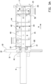
- FIG. 1 An isometric view of a processing device 1 for processing one or more flowable materials, such as pharmaceuticals, according to an embodiment of the invention is shown in figure 1 .
- the processing device 1 comprises an elongated cylindrical housing 2 in which an internal cylindrical processing chamber 3 is defined.
- the cylindrical housing 2 has a first end 4 and a second end 5, in longitudinal direction opposite to the first end 4.
- the cylindrical housing 2 is coupled to a non-shown driving unit, schematically represented by a driving axle 6.
- the non-shown driving unit bounds the processing chamber 3 at the first end 4 of the cylindrical housing 3.
- the cylindrical housing 2 is provided with a closure plate 7 for bounding the processing chamber 3 at the second end 5 of the cylindrical housing 2.
- the cylindrical housing 2 has a circular cylindrical circumferential wall 20 with a horizontal centerline S.
- the circular cylindrical circumferential wall 20 defines at the inside thereof a circular cylindrical inner surface 21 of the processing chamber 3.
- the circular cylindrical circumferential wall 20 merges at the first end 4 thereof, which is the side facing the non-shown driving unit, into a first coupling flange 22, and merges at the second end 5 thereof, which is the side facing away from the non-shown driving unit, into a second coupling flange 23.
- the cylindrical housing 2 is provided with an inlet conduit 30 having a circular cylindrical inlet tube 31 with a vertical centerline K.
- the circular cylindrical inlet tube 31 is provided at or near the first end 4 of the cylindrical housing 2.
- the circular cylindrical inlet tube 31 is arranged at the top side of the circular cylindrical circumferential wall 20 and debouches tangentially into the processing chamber 3. Therefore, the circular cylindrical inlet tube 31 merges smoothly into the circular cylindrical inner surface 21 of the processing chamber 3 at a position remote from the horizontal centerline S.
- the cylindrical housing 2 is further provided with an outlet conduit 35 having a circular cylindrical outlet tube 36 met a vertical centerline L.
- the circular cylindrical outlet tube 36 is provided at or near the second end 5 of the cylindrical housing 2.
- the circular cylindrical outlet tube 36 is arranged at the bottom side of the circular cylindrical wall 20 and debouches tangentially into the processing chamber 3.
- the circular cylindrical outlet tube 36 merges smoothly into the circular cylindrical inner surface 21 of the processing chamber 3 at a position remote from the horizontal centerline S.
- the circular cylindrical outlet tube 36 is, in the circumferential direction around the horizontal centerline S, in line with the circular cylindrical inlet tube 31.
- the first coupling flange 22 is placed against the partition disc coupling flange 13, wherein a first sealing ring 14 is placed therebetween.
- the first coupling flange 22 and the partition disc coupling flange 13 can be coupled by means of a non-shown first clamping ring.
- the closure plate 7 is placed against the second coupling flange 23 of the cylindrical housing 2, wherein a second sealing ring 15 is placed therebetween.
- the closure plate 7 and the second coupling flange 23 can be coupled by means of a non-shown second clamping ring.
- the processing device 1 comprises a straight agitating rotor 40 arranged with the processing chamber 3.
- the agitating rotor 40 extends from a bearing 41 within the partition disc 10 through the first coupling flange 22 and through the processing chamber 3.
- the agitating rotor 40 is connected to the driving axle 6 in order to rotate the agitating rotor 40 in a rotating direction R.
- the agitating rotor 40 is arranged concentric within the processing chamber 3, such that the agitating rotor centerline coincidences with the horizontal centerline of the cylindrical housing 2.
- the agitating rotor 40 comprises an agitating axle 42 arranged concentric within the processing chamber 3, and a plurality of agitating members 43 arranged at the agitating axle 42 and extending therefrom in a radial outward direction.
- each of the agitating members 43 comprises an agitating shaft 44 arranged at the agitating axle 42 at one end thereof.
- Each agitating member 43 further comprises an agitating vane 45 at the end of the respective agitating shaft 44 facing away from the agitating axle 42.
- Each of the agitating vanes 45 defines a displacement plane or main plane extending parallel to the respective agitating shaft 44 and extending at an angle with respect to the horizontal centerline S.
- the agitating rotor 40 is further provided with scraping members 46.
- Each of the scraping members 46 is provided with a scraping shaft 47 arranged at the agitating axle 42 at one end thereof.
- Each scraping member 46 further comprises a scraping vane 48 having a scraping edge 49 for contacting and scraping over a surface of the partition disc 10 or the closure plate 7.
- the processing device 1 further comprises a dust directing member 50, also called a dust disc 50, removably arranged at the agitating rotor 40.
- the dust directing member 50 has a substantially circular directing body 51.
- the circular directing body 51 has a first semi-circular body portion 52 and a second semi-circular body portion 53.
- Each of the semi-circular body portions 52, 53 has a convex-shaped edge 54 and a straight edge 55, wherein the straight edges 55 of the first and second semi-circular body portions 52, 53 are facing towards each other.
- Each of the straight edges 55 has a semi-circular recess 56 at the center thereof, wherein the semi-circular recesses 56 of the first and second semi-circular body portions 52, 53 together define a passage 57 for allowing the agitating axle 42 to pass therethrough. Additionally, each of the straight edges 55 comprises a first deepening 58 at a first end thereof, and a second deepening 59 at a second end thereof. The first deepenings 58 of the first and second semi-circular body portions 52, 53 together define a first receiving space 60, and the second deepenings 59 of the first and second semi-circular body portions 52, 53 together define a second receiving space 61. The first and second receiving spaces 60, 61 are configured for receiving a part of the agitating vane 45 of one of the agitating members 43.
- Each of the first and second semi-circular body portions 52, 53 comprises a securing member 65 provided at a side of the respective semi-circular body portion 52, 53.
- Each securing member 65 has a securing body 66, with a first securing body end 67 and a second securing body end 68, extending around the semi-circular recess 56 of the respective semi-circular body portions 52, 53.
- the securing body 66 at the first semi-circular body portion 52 has an opposite orientation to the securing body 66 at the second semi-circular body portion 53.
- each of the securing bodies 66 is provided with a securing face 69, facing towards the other one of the first and second semi-circular body portions 52, 53, and a receiving opening 70 at the securing face 69 configured to receive a securing part 71, such as a screw or a bolt.
- each of the securing bodies 66 is provided with a securing extension 72 extending away from the securing body 66 and substantially parallel to the straight edge 55 of the respective semi-circular body portion 52, 53.
- each securing extension 72 of the securing body 66 at one of the first and second semi-circular body portions 52, 53 is configured to be arranged against the securing face 69 of the other one of the first and second semi-circular body portion 52, 53.
- each securing extension 72 has an extension body with a receiving passage 74 for allowing the securing part 71 to pass therethrough, such that the dust directing member 50 can be removably arranged at the agitating axle 42.
- the processing chamber 3 has a first diameter D1 and the dust directing member 50 has a second diameter D2.
- the second diameter D2 is smaller than the first diameter D1 in order to realize a narrow passage between the outer circumference of the dust directing member 50 and the circular cylindrical inner surface 21 of the processing chamber 3.
- the first diameter is 134 mm and the second diameter is 128 mm, such that the distance between the outer circumference of the dust directing member 50 and the circular cylindrical inner surface 21 of the processing chamber 3 is approximately 3 mm.
- the agitating rotor 40 is rotated at a rotation speed in the range between 400 and 1500 rpm.
- the agitating vanes 45 therefore, generate an under pressure within the inlet conduit 30 and an over pressure within the outlet conduit 35, such that an air flow from the inlet conduit 30 to the outlet conduit 35 is generated.
- a combination of two or more flowable materials to be mixed is introduced into the processing chamber 3 via the inlet conduit 30.
- the agitating vanes 45 apply due to the rotating motion an centrifugal force to the combination of two or more flowable materials, therewith forcing the two or more flowable materials towards the outside of the processing chamber 3.
- the combination of two or more flowable materials moves spirally close to the circular cylindrical inner surface 21 of the processing chamber 3 in a movement direction M, therewith forming an annular layer along the circular cylindrical inner surface 21.
- the combination of two or more flowable materials moves through the processing chamber 3 towards the outlet conduit 35, while passing the dust disc 50.
- the dust disc 50 provides a barrier along which the annular layer of the combination of two or more flowable materials is forced to pass. Dust floating around and moving along the agitating axle 42, therewith being remote from the annular layer of the combination of two or more flowable materials, is stopped by the dust disc 50 and forced towards the outside of the processing chamber 3, i.e. towards the annular layer of two or more flowable materials moving along the circular cylindrical inner surface 21 of the processing chamber 3. Therefore, the part of the processing chamber 3 beyond the dust disc 50, when viewed in the movement direction M, is substantially free of dust. Subsequently, the combination of two or more flowable materials, which are mixed at this stage, fall out of the processing chamber 3 through the outlet conduit 35 under influence of gravity.
- FIG. 5 An isometric view of a processing device 101 according to a further embodiment of the invention is shown in figure 5 .
- the processing device 101 has substantially the same features as the processing device 1. Therefore, similar features are referred to with the same reference number increased with 100.
- the processing device 101 differs from the processing device 1 as described in relation to figures 1-4 , in that the processing device 101 comprises an additional inlet conduit 132 having an additional circular cylindrical inlet tube 133 with a vertical centerline T.
- the additional circular cylindrical inlet tube 133 is provided in front of the dust disc 150, when viewed in the movement direction M. Similar to the circular cylindrical inlet tube 131, the additional circular cylindrical inlet tube 133 is arranged at the top side of the circular cylindrical circumferential wall 120 and debouches tangentially into the processing chamber 103. Therefore, the additional circular cylindrical inlet tube 133 merges smoothly into the circular cylindrical inner surface 121 of the processing chamber 103 at a position remote from the horizontal centerline S.
- This embodiment of the processing device 101 provides an additional inlet location, such that, for example, a first flowable material can be introduced into the processing chamber 103 via the inlet conduit 130, and a second flowable material can be introduced into the processing chamber 103 via the additional inlet conduit 132.
- FIG. 6 A cross-sectional view of a processing device 201 according to a further embodiment of the invention is shown in figure 6 .
- the processing device 201 has substantially the same features as the processing device 1. Therefore, similar features are referred to with the same reference number increased with 200.
- the processing device 201 differs from the processing device 1 as described in relation to figures 1-4 , in that the processing device 201 comprises an additional dust directing member 280, also called additional dust disc 280, is arranged at the agitating axle 242 directly downstream of the inlet conduit 230.
- additional dust directing member 280 also called additional dust disc 280
Landscapes
- Engineering & Computer Science (AREA)
- Chemical & Material Sciences (AREA)
- Chemical Kinetics & Catalysis (AREA)
- Mechanical Engineering (AREA)
- General Engineering & Computer Science (AREA)
- Mixers Of The Rotary Stirring Type (AREA)
Claims (15)
- Verarbeitungsvorrichtung (1, 101, 201) zum Verarbeiten eines oder mehrerer fließfähiger Materialien, wie zum Beispiel Arzneimittel, wobei die Verarbeitungsvorrichtung (1, 101, 201) folgende Merkmale aufweist:ein Gehäuse (2, 102), das eine zylindrische Verarbeitungskammer (3, 103) aufweist, und einen Einlass (30, 130, 230) in Fluidkommunikation mit der Verarbeitungskammer (3, 103) und einen Auslass (35, 135) in Fluidkommunikation mit der Verarbeitungskammer (3, 103) und in einem Abstand zu dem Einlass (30, 130, 230) in einer Richtung entlang der Längsrichtung der zylindrischen Verarbeitungskammer (3, 103) aufweist; undeinen Rührrotor (40, 240), der in der Verarbeitungskammer (3, 103) axial angeordnet ist und konfiguriert ist zum Rühren eines oder mehrerer fließfähiger Materialien in der Verarbeitungskammer (3, 103), wobei der Rührrotor (40, 240) dazu konfiguriert ist, sich zu drehen, um das eine oder die mehreren fließfähigen Materialien in dem Gefäß derart zu rühren, dass das eine oder die mehreren fließfähigen Materialien in der zylindrischen Verarbeitungskammer (3, 103) als ein ringförmiges fluidisiertes Bett beibehalten werden,wobei die Verarbeitungsvorrichtung (1, 101, 201) ferner ein Staubleitbauglied (50, 150, 250) aufweist, das an dem Rührrotor (40, 240) und an oder nahe dem Auslass (35, 135) angeordnet ist, und konfiguriert ist, im Wesentlichen zu verhindern, dass eine Staubwolke in der Verarbeitungskammer (3, 103) den Auslass (35, 135) erreicht, und die Staubwolke zu dem ringförmigen fluidisierten Bett zu leiten, wodurch die Staubwolke in das ringförmige fluidisierte Bett eingebracht wird, wobei das Staubleitbauglied (50, 150, 250) einen im Wesentlichen kreisförmigen Leitkörper (51) aufweist, der sich im Wesentlichen quer zu der Längsrichtung des Rührrotors (40, 240) erstreckt,wobei die zylindrische Verarbeitungskammer (3, 103) eine kreisförmige zylindrische Verarbeitungskammer (3, 103) mit einem ersten Durchmesser (D1) ist, wobei der im Wesentlichen kreisförmige Leitkörper (51) einen zweiten Durchmesser (D2) aufweist, wobei der zweite Durchmesser (D2) kleiner ist als der erste Durchmesser (D1), und wobei die zylindrische Verarbeitungskammer (3, 103) eine zylindrische Innenoberfläche (21, 121, 221) aufweist und der im Wesentlichen kreisförmige Leitkörper (51) einen Außenumfang aufweist, wobei ein Abstand zwischen der zylindrischen Innenoberfläche (21, 121, 221) der zylindrischen Verarbeitungskammer (3, 103) und dem Außenumfang des im Wesentlichen kreisförmigen Leitkörpers (51) in dem Bereich zwischen 2 und 20 mm liegt, beispielsweise 3 mm, wenn der erste Durchmesser (D1) etwa 134 mm beträgt, oder in dem Bereich zwischen 1 % und 17 %, vorzugsweise zwischen 1,5 % und 15 % des ersten Durchmessers (D1).
- Verarbeitungsvorrichtung (1, 101, 201) gemäß Anspruch 1, bei der das Staubleitbauglied (50, 150, 250) an dem Rührrotor (40, 240) herausnehmbar angeordnet ist.
- Verarbeitungsvorrichtung (1, 101, 201) gemäß Anspruch 1, bei der der im Wesentlichen kreisförmige Leitkörper (51) einen ersten halbkreisförmigen Körperabschnitt (52) und einen zweiten halbkreisförmigen Körperabschnitt (53) aufweist, wobei jeder des ersten und zweiten halbkreisförmigen Körperabschnitts (52, 53) einen konvexförmigen Rand (54) und einen geraden Rand (55) aufweist, wobei vorzugsweise die geraden Ränder (55) des ersten und zweiten halbkreisförmigen Körperabschnitts (52, 53) einander zugewandt sind.
- Verarbeitungsvorrichtung (1, 101, 201) gemäß Anspruch 3, bei der jeder der geraden Ränder (55) eine halbkreisförmige Ausnehmung (56) in der Mitte desselben aufweist, wobei die halbkreisförmigen Ausnehmungen (56) des ersten und zweiten Körperabschnitts (52, 53) zusammen einen Durchgang (57) definieren, um es dem Rührrotor (40, 240) zu ermöglichen, durch denselben zu verlaufen.
- Verarbeitungsvorrichtung (1, 101, 201) gemäß Anspruch 3 oder Anspruch 4, bei der der erste und zweite halbkreisförmige Körperabschnitt (52, 53) angeordnet sind, um aneinander befestigt zu sein.
- Verarbeitungsvorrichtung (1, 101, 201) gemäß einem der Ansprüche 3 bis 5, bei der jeder des ersten und zweiten halbkreisförmigen Körperabschnitts (52, 53) ein Befestigungsbauglied (65) zum Befestigen des ersten und zweiten halbkreisförmigen Körperabschnitts (52, 53) aneinander aufweist.
- Verarbeitungsvorrichtung (1, 101, 201) gemäß Anspruch 6, bei der jedes Befestigungsbauglied (65) einen Befestigungskörper (66) mit einem ersten Befestigungskörperende (67) und einem zweiten Befestigungskörperende (68) aufweist, wobei jeder der Befestigungskörper (66) an dem ersten Ende (67) mit einer Befestigungsfläche (69) und einer Aufnahmeöffnung (70) an der Befestigungsfläche (69) versehen ist, die dazu konfiguriert ist, ein Befestigungsteil (71) aufzunehmen, wobei jeder der Befestigungskörper (66) an dem zweiten Ende (68) mit einer Befestigungserstreckung (72) versehen ist, die sich weg von dem Befestigungskörper (66) und im Wesentlichen parallel zu dem geraden Rand (55) des jeweiligen kreisförmigen Körperabschnitts (52, 53) erstreckt und dazu konfiguriert ist, an der Befestigungsfläche (69) des anderen Befestigungsbauglieds (65) angeordnet zu sein, wobei jede Befestigungserstreckung (72) einen Erstreckungskörper (73) mit einem Aufnahmedurchgang (74) aufweist, um es dem Befestigungsteil (71) zu ermöglichen, durch denselben zu verlaufen.
- Verarbeitungsvorrichtung (1, 101, 201) gemäß Anspruch 4 und Anspruch 7, bei der jedes Befestigungsbauglied (65) sich um die halbkreisförmige Ausnehmung (56) des jeweiligen halbkreisförmigen Körperabschnitts (52, 53) erstreckt, und wobei der Befestigungskörper (66) an dem ersten halbkreisförmigen Körperabschnitt (52) eine entgegengesetzte Ausrichtung zu dem Befestigungskörper (66) an dem zweiten halbkreisförmigen Körperabschnitt (53) aufweist.
- Verarbeitungsvorrichtung (1, 101, 201) gemäß einem der vorhergehenden Ansprüche, bei der der Rührrotor (40, 240) eine Rührachse (42, 242), die in der Verarbeitungskammer (3, 103) konzentrisch angeordnet ist, und eine Mehrzahl von Rührbaugliedern (43) aufweist, die an der Rührachse (42, 242) angeordnet sind und sich von derselben in einer radialen Auswärtsrichtung erstrecken.
- Verarbeitungsvorrichtung (1, 101, 201) gemäß einem der vorhergehenden Ansprüche, bei der jedes der Rührbauglieder (43) eine Rührwelle (44, 244), die an der Rührachse (42, 242) an einem Ende derselben angeordnet ist, und einen Rührflügel (45) aufweist, der an dem Ende der jeweiligen Rührwelle (44, 244) angeordnet ist, das von der Rührachse (42, 242) abgewandt ist.
- Verarbeitungsvorrichtung (1, 101, 201) gemäß Anspruch 10, in Abhängigkeit von Anspruch 3, wobei die geraden Ränder (55) des ersten und zweiten halbkreisförmigen Körperabschnitts (52, 53) mit einer ersten und zweiten Vertiefung (59) versehen sind, die konfiguriert sind zum Definieren eines ersten und zweiten Aufnahmeraums (60, 61) zum Aufnehmen eines Teils eines Rührflügels (45).
- Verarbeitungsvorrichtung (1, 101, 201) gemäß einem der vorhergehenden Ansprüche, wobei die Verarbeitungsvorrichtung (1, 101, 201) zwei oder mehr Staubleitbauglieder (50, 150, 250, 280) aufweist; und/oder
wobei die Verarbeitungsvorrichtung (1, 101, 201) aus einer Gruppe ausgewählt ist, die einen Mischer, vorzugsweise einen ringförmigen Mischer, einen Rührer und einen Trockner aufweist. - Verarbeitungssystem zum Verarbeiten eines oder mehrerer fließfähiger Materialien, wie zum Beispiel Arzneimittel, wobei das System folgende Merkmale aufweist:eine oder mehrere Zuführeinrichtungen, die konfiguriert sind zum Zuführen eines oder mehrerer fließfähiger Materialien zu der Verarbeitungsvorrichtung (1, 101, 201); undeine Verarbeitungsvorrichtung (1, 101, 201) zum Verarbeiten des einen oder der mehreren fließfähigen Materialien gemäß einem der vorhergehenden Ansprüche.
- Verarbeitungsverfahren zum Verarbeiten eines oder mehrerer fließfähiger Materialien, wie zum Beispiel Arzneimittel, durch eine Verarbeitungsvorrichtung (1, 101, 201) zum Verarbeiten eines oder mehrerer fließfähiger Materialien gemäß einem der Ansprüche 1 bis 12, wobei das Verfahren folgende Schritte aufweist:Bereitstellen eines oder mehrerer zu verarbeitender fließfähiger Materialien an die Verarbeitungsvorrichtung (1, 101, 201) zum Verarbeiten eines oder mehrerer fließfähiger Materialien;Verarbeiten des einen oder der mehreren zu verarbeitenden fließfähigen Materialien durch die Verarbeitungsvorrichtung (1, 101, 201) durch Drehen des Rührrotors (40, 240) zum Rühren des einen oder der mehreren fließfähigen Materialien in dem Gefäß, derart, dass das eine oder die mehreren fließfähigen Materialien in der zylindrischen Verarbeitungskammer (3, 103) als ein ringförmiges fluidisiertes Bett beibehalten werden; undAblassen des verarbeiteten einen oder der mehreren Materialien von der Verarbeitungsvorrichtung (1, 101, 201),wobei das Verfahren während des Schritts des Verarbeitens des einen oder der mehreren fließfähigen Materialien ferner die Schritte, durch das Staubleitbauglied (50, 150, 250), des im Wesentlichen Verhinderns, dass eine Staubwolke in der Verarbeitungskammer (3, 103) den Auslass (35, 135) erreicht, und des Leitens der Staubwolke zu dem ringförmigen fluidisierten Bett aufweist, wodurch die Staubwolke in das ringförmige fluidisierte Bett eingebracht wird.
- Verfahren gemäß Anspruch 14, bei dem der Schritt des Bereitstellens eines oder mehrerer fließfähiger Materialien an die Verarbeitungsvorrichtung (1, 101, 201) zum Verarbeiten eines oder mehrerer fließfähiger Materialien den Schritt des Bereitstellens eines oder mehrerer zulässiger pharmazeutischer Wirkstoffe (API) und/oder eines oder mehrerer Trägerstoffe aufweist; und/oder
wobei der Schritt des Bereitstellens eines oder mehrerer zu verarbeitender fließfähiger Materialien an die Verarbeitungsvorrichtung (1, 101, 201) zum Verarbeiten eines oder mehrerer fließfähiger Materialien den Schritt des Bereitstellens von zwei oder mehreren zu verarbeitenden fließfähigen Materialien an die Verarbeitungsvorrichtung (1, 101, 201) aufweist, wobei der Schritt des Verarbeitens des einen oder der mehreren zu verarbeitenden fließfähigen Materialien durch die Verarbeitungsvorrichtung (1, 101, 201) vorzugsweise den Schritt des Mischens von zwei oder mehreren fließfähigen Materialien aufweist.
Applications Claiming Priority (2)
| Application Number | Priority Date | Filing Date | Title |
|---|---|---|---|
| NL2025396A NL2025396B1 (en) | 2020-04-22 | 2020-04-22 | Processing device for processing one or more flowable materials |
| PCT/NL2021/050258 WO2021215918A1 (en) | 2020-04-22 | 2021-04-21 | Processing device for processing one or more flowable materials |
Publications (3)
| Publication Number | Publication Date |
|---|---|
| EP4139619A1 EP4139619A1 (de) | 2023-03-01 |
| EP4139619B1 true EP4139619B1 (de) | 2024-07-17 |
| EP4139619C0 EP4139619C0 (de) | 2024-07-17 |
Family
ID=70614563
Family Applications (1)
| Application Number | Title | Priority Date | Filing Date |
|---|---|---|---|
| EP21722320.5A Active EP4139619B1 (de) | 2020-04-22 | 2021-04-21 | Verarbeitungsvorrichtung zur verarbeitung eines oder mehrerer fliessfähiger materialien |
Country Status (3)
| Country | Link |
|---|---|
| EP (1) | EP4139619B1 (de) |
| NL (1) | NL2025396B1 (de) |
| WO (1) | WO2021215918A1 (de) |
Family Cites Families (7)
| Publication number | Priority date | Publication date | Assignee | Title |
|---|---|---|---|---|
| US2756971A (en) * | 1953-09-30 | 1956-07-31 | Du Pont | Liquid mixing apparatus |
| US3425135A (en) | 1964-09-11 | 1969-02-04 | Strong Mfg Co Scott | Rotary solids processing apparatus and method |
| CH657069A5 (de) * | 1982-10-04 | 1986-08-15 | List Ind Verfahrenstech | Heiz- und kuehlbarer scheibenruehrer. |
| US5570517A (en) * | 1995-02-13 | 1996-11-05 | Scott Equipement Company | Slurry dryer |
| BR9917506A (pt) * | 1999-10-05 | 2002-08-13 | Rubicon Dev Company L L C | Aparelho desidratador de lama que opera no modo de batelada |
| KR101124536B1 (ko) * | 2009-12-02 | 2012-03-19 | (주)태신 | 디스크 건조기 |
| GB2507487A (en) * | 2012-10-30 | 2014-05-07 | Ashe Morris Ltd | Rotating flow reactor |
-
2020
- 2020-04-22 NL NL2025396A patent/NL2025396B1/en not_active IP Right Cessation
-
2021
- 2021-04-21 EP EP21722320.5A patent/EP4139619B1/de active Active
- 2021-04-21 WO PCT/NL2021/050258 patent/WO2021215918A1/en not_active Ceased
Also Published As
| Publication number | Publication date |
|---|---|
| NL2025396B1 (en) | 2021-10-28 |
| EP4139619A1 (de) | 2023-03-01 |
| WO2021215918A1 (en) | 2021-10-28 |
| EP4139619C0 (de) | 2024-07-17 |
Similar Documents
| Publication | Publication Date | Title |
|---|---|---|
| CN103298561B (zh) | 用于搅拌式球磨机的分离装置的动态元件 | |
| US8002213B2 (en) | Agitator mill | |
| US5570517A (en) | Slurry dryer | |
| CN87102245A (zh) | 一种使粉末物料与液体(基本上是水泥和水)或两相液体相混合的混合器 | |
| KR102501892B1 (ko) | 교반기 볼 밀 | |
| CN101287554A (zh) | 搅拌式研磨机 | |
| US4214712A (en) | Micro-mill-mixer | |
| JP7166351B2 (ja) | 分級ローター及び分級装置 | |
| EP0618845A1 (de) | Einlassbeschleunigungsvorrichtung mit beschleunigungsschaufelgerät | |
| JPS5816929B2 (ja) | 混練機 | |
| TWI604891B (zh) | Media mixing mill | |
| CN110139707B (zh) | 分散装置、脱泡装置 | |
| KR101409595B1 (ko) | 분립체 공급기 | |
| EP4139619B1 (de) | Verarbeitungsvorrichtung zur verarbeitung eines oder mehrerer fliessfähiger materialien | |
| US1496641A (en) | Mixing, incorporating, and disintegrating machine | |
| US4582266A (en) | Centrifugal media mill | |
| US4106117A (en) | Apparatus for mixing particulate material in a liquid | |
| JP5046557B2 (ja) | メディア攪拌型湿式分散機及び微粒子の分散方法 | |
| JP2898523B2 (ja) | 分散装置および分散方法 | |
| CN117794633A (zh) | 分散单元 | |
| JP2969555B2 (ja) | 遠心分級機 | |
| SU1745322A1 (ru) | Центробежный смеситель | |
| CN112916215B (zh) | 碟式分离机的密封结构 | |
| RU2216394C1 (ru) | Центробежный смеситель | |
| RU2198094C1 (ru) | Смеситель |
Legal Events
| Date | Code | Title | Description |
|---|---|---|---|
| STAA | Information on the status of an ep patent application or granted ep patent |
Free format text: STATUS: UNKNOWN |
|
| STAA | Information on the status of an ep patent application or granted ep patent |
Free format text: STATUS: THE INTERNATIONAL PUBLICATION HAS BEEN MADE |
|
| PUAI | Public reference made under article 153(3) epc to a published international application that has entered the european phase |
Free format text: ORIGINAL CODE: 0009012 |
|
| STAA | Information on the status of an ep patent application or granted ep patent |
Free format text: STATUS: REQUEST FOR EXAMINATION WAS MADE |
|
| 17P | Request for examination filed |
Effective date: 20221122 |
|
| AK | Designated contracting states |
Kind code of ref document: A1 Designated state(s): AL AT BE BG CH CY CZ DE DK EE ES FI FR GB GR HR HU IE IS IT LI LT LU LV MC MK MT NL NO PL PT RO RS SE SI SK SM TR |
|
| P01 | Opt-out of the competence of the unified patent court (upc) registered |
Effective date: 20230417 |
|
| DAV | Request for validation of the european patent (deleted) | ||
| DAX | Request for extension of the european patent (deleted) | ||
| STAA | Information on the status of an ep patent application or granted ep patent |
Free format text: STATUS: EXAMINATION IS IN PROGRESS |
|
| 17Q | First examination report despatched |
Effective date: 20231106 |
|
| GRAP | Despatch of communication of intention to grant a patent |
Free format text: ORIGINAL CODE: EPIDOSNIGR1 |
|
| STAA | Information on the status of an ep patent application or granted ep patent |
Free format text: STATUS: GRANT OF PATENT IS INTENDED |
|
| RIC1 | Information provided on ipc code assigned before grant |
Ipc: F26B 25/04 20060101ALI20240119BHEP Ipc: F26B 11/16 20060101AFI20240119BHEP |
|
| INTG | Intention to grant announced |
Effective date: 20240206 |
|
| GRAS | Grant fee paid |
Free format text: ORIGINAL CODE: EPIDOSNIGR3 |
|
| GRAA | (expected) grant |
Free format text: ORIGINAL CODE: 0009210 |
|
| STAA | Information on the status of an ep patent application or granted ep patent |
Free format text: STATUS: THE PATENT HAS BEEN GRANTED |
|
| AK | Designated contracting states |
Kind code of ref document: B1 Designated state(s): AL AT BE BG CH CY CZ DE DK EE ES FI FR GB GR HR HU IE IS IT LI LT LU LV MC MK MT NL NO PL PT RO RS SE SI SK SM TR |
|
| REG | Reference to a national code |
Ref country code: CH Ref legal event code: EP |
|
| REG | Reference to a national code |
Ref country code: DE Ref legal event code: R096 Ref document number: 602021015834 Country of ref document: DE |
|
| REG | Reference to a national code |
Ref country code: IE Ref legal event code: FG4D |
|
| U01 | Request for unitary effect filed |
Effective date: 20240816 |
|
| U07 | Unitary effect registered |
Designated state(s): AT BE BG DE DK EE FI FR IT LT LU LV MT NL PT SE SI Effective date: 20240823 |
|
| P04 | Withdrawal of opt-out of the competence of the unified patent court (upc) registered |
Free format text: CASE NUMBER: APP_48238/2024 Effective date: 20240821 |
|
| P05 | Withdrawal of opt-out of the competence of the unified patent court (upc) changed |
Free format text: CASE NUMBER: APP_48238/2024 Effective date: 20240823 |
|
| PG25 | Lapsed in a contracting state [announced via postgrant information from national office to epo] |
Ref country code: NO Free format text: LAPSE BECAUSE OF FAILURE TO SUBMIT A TRANSLATION OF THE DESCRIPTION OR TO PAY THE FEE WITHIN THE PRESCRIBED TIME-LIMIT Effective date: 20241017 |
|
| PG25 | Lapsed in a contracting state [announced via postgrant information from national office to epo] |
Ref country code: GR Free format text: LAPSE BECAUSE OF FAILURE TO SUBMIT A TRANSLATION OF THE DESCRIPTION OR TO PAY THE FEE WITHIN THE PRESCRIBED TIME-LIMIT Effective date: 20241018 Ref country code: PL Free format text: LAPSE BECAUSE OF FAILURE TO SUBMIT A TRANSLATION OF THE DESCRIPTION OR TO PAY THE FEE WITHIN THE PRESCRIBED TIME-LIMIT Effective date: 20240717 |
|
| PG25 | Lapsed in a contracting state [announced via postgrant information from national office to epo] |
Ref country code: IS Free format text: LAPSE BECAUSE OF FAILURE TO SUBMIT A TRANSLATION OF THE DESCRIPTION OR TO PAY THE FEE WITHIN THE PRESCRIBED TIME-LIMIT Effective date: 20241117 |
|
| PG25 | Lapsed in a contracting state [announced via postgrant information from national office to epo] |
Ref country code: HR Free format text: LAPSE BECAUSE OF FAILURE TO SUBMIT A TRANSLATION OF THE DESCRIPTION OR TO PAY THE FEE WITHIN THE PRESCRIBED TIME-LIMIT Effective date: 20240717 |
|
| PG25 | Lapsed in a contracting state [announced via postgrant information from national office to epo] |
Ref country code: RS Free format text: LAPSE BECAUSE OF FAILURE TO SUBMIT A TRANSLATION OF THE DESCRIPTION OR TO PAY THE FEE WITHIN THE PRESCRIBED TIME-LIMIT Effective date: 20241017 Ref country code: ES Free format text: LAPSE BECAUSE OF FAILURE TO SUBMIT A TRANSLATION OF THE DESCRIPTION OR TO PAY THE FEE WITHIN THE PRESCRIBED TIME-LIMIT Effective date: 20240717 |
|
| PG25 | Lapsed in a contracting state [announced via postgrant information from national office to epo] |
Ref country code: RS Free format text: LAPSE BECAUSE OF FAILURE TO SUBMIT A TRANSLATION OF THE DESCRIPTION OR TO PAY THE FEE WITHIN THE PRESCRIBED TIME-LIMIT Effective date: 20241017 Ref country code: PL Free format text: LAPSE BECAUSE OF FAILURE TO SUBMIT A TRANSLATION OF THE DESCRIPTION OR TO PAY THE FEE WITHIN THE PRESCRIBED TIME-LIMIT Effective date: 20240717 Ref country code: NO Free format text: LAPSE BECAUSE OF FAILURE TO SUBMIT A TRANSLATION OF THE DESCRIPTION OR TO PAY THE FEE WITHIN THE PRESCRIBED TIME-LIMIT Effective date: 20241017 Ref country code: IS Free format text: LAPSE BECAUSE OF FAILURE TO SUBMIT A TRANSLATION OF THE DESCRIPTION OR TO PAY THE FEE WITHIN THE PRESCRIBED TIME-LIMIT Effective date: 20241117 Ref country code: HR Free format text: LAPSE BECAUSE OF FAILURE TO SUBMIT A TRANSLATION OF THE DESCRIPTION OR TO PAY THE FEE WITHIN THE PRESCRIBED TIME-LIMIT Effective date: 20240717 Ref country code: GR Free format text: LAPSE BECAUSE OF FAILURE TO SUBMIT A TRANSLATION OF THE DESCRIPTION OR TO PAY THE FEE WITHIN THE PRESCRIBED TIME-LIMIT Effective date: 20241018 Ref country code: ES Free format text: LAPSE BECAUSE OF FAILURE TO SUBMIT A TRANSLATION OF THE DESCRIPTION OR TO PAY THE FEE WITHIN THE PRESCRIBED TIME-LIMIT Effective date: 20240717 |
|
| PG25 | Lapsed in a contracting state [announced via postgrant information from national office to epo] |
Ref country code: SM Free format text: LAPSE BECAUSE OF FAILURE TO SUBMIT A TRANSLATION OF THE DESCRIPTION OR TO PAY THE FEE WITHIN THE PRESCRIBED TIME-LIMIT Effective date: 20240717 |
|
| U20 | Renewal fee for the european patent with unitary effect paid |
Year of fee payment: 5 Effective date: 20250311 |
|
| PG25 | Lapsed in a contracting state [announced via postgrant information from national office to epo] |
Ref country code: CZ Free format text: LAPSE BECAUSE OF FAILURE TO SUBMIT A TRANSLATION OF THE DESCRIPTION OR TO PAY THE FEE WITHIN THE PRESCRIBED TIME-LIMIT Effective date: 20240717 |
|
| PG25 | Lapsed in a contracting state [announced via postgrant information from national office to epo] |
Ref country code: SK Free format text: LAPSE BECAUSE OF FAILURE TO SUBMIT A TRANSLATION OF THE DESCRIPTION OR TO PAY THE FEE WITHIN THE PRESCRIBED TIME-LIMIT Effective date: 20240717 |
|
| PLBE | No opposition filed within time limit |
Free format text: ORIGINAL CODE: 0009261 |
|
| STAA | Information on the status of an ep patent application or granted ep patent |
Free format text: STATUS: NO OPPOSITION FILED WITHIN TIME LIMIT |
|
| 26N | No opposition filed |
Effective date: 20250422 |
|
| REG | Reference to a national code |
Ref country code: CH Ref legal event code: H13 Free format text: ST27 STATUS EVENT CODE: U-0-0-H10-H13 (AS PROVIDED BY THE NATIONAL OFFICE) Effective date: 20251125 |
|
| PG25 | Lapsed in a contracting state [announced via postgrant information from national office to epo] |
Ref country code: MC Free format text: LAPSE BECAUSE OF FAILURE TO SUBMIT A TRANSLATION OF THE DESCRIPTION OR TO PAY THE FEE WITHIN THE PRESCRIBED TIME-LIMIT Effective date: 20240717 |
|
| GBPC | Gb: european patent ceased through non-payment of renewal fee |
Effective date: 20250421 |
|
| PG25 | Lapsed in a contracting state [announced via postgrant information from national office to epo] |
Ref country code: GB Free format text: LAPSE BECAUSE OF NON-PAYMENT OF DUE FEES Effective date: 20250421 |
|
| PG25 | Lapsed in a contracting state [announced via postgrant information from national office to epo] |
Ref country code: CH Free format text: LAPSE BECAUSE OF NON-PAYMENT OF DUE FEES Effective date: 20250430 |